edinburgh research explorer · 10.1021/jacs.6b04956 link: link to publication record in edinburgh...
TRANSCRIPT
Edinburgh Research Explorer
Interdye Hole Transport Accelerates Recombination in DyeSensitized Mesoporous Films
Citation for published version:Moia, D, Szumska, A, Vaissier, V, Planells, M, Robertson, N, O’regan, BC, Nelson, J & Barnes, PRF 2016,'Interdye Hole Transport Accelerates Recombination in Dye Sensitized Mesoporous Films' Journal of theAmerican Chemical Society, vol 138, no. 40, pp. 13197-13206. DOI: 10.1021/jacs.6b04956
Digital Object Identifier (DOI):10.1021/jacs.6b04956
Link:Link to publication record in Edinburgh Research Explorer
Document Version:Peer reviewed version
Published In:Journal of the American Chemical Society
General rightsCopyright for the publications made accessible via the Edinburgh Research Explorer is retained by the author(s)and / or other copyright owners and it is a condition of accessing these publications that users recognise andabide by the legal requirements associated with these rights.
Take down policyThe University of Edinburgh has made every reasonable effort to ensure that Edinburgh Research Explorercontent complies with UK legislation. If you believe that the public display of this file breaches copyright pleasecontact [email protected] providing details, and we will remove access to the work immediately andinvestigate your claim.
Download date: 29. May. 2018

1
Inter-dye hole transport accelerates recombination in dye
sensitized mesoporous films
Davide Moia,1* Anna Szumska,1 Valérie Vaissier,1** Miquel Planells,2 Neil Robertson,2 Brian C.
O’Regan,3 Jenny Nelson,1 Piers R. F. Barnes1*
1 Blackett Laboratory, Imperial College London, Prince Consort Road, London SW7 2AZ, UK
2 EaStCHEM School of Chemistry, University of Edinburgh, King’s Buildings, David Brewster Road,
Edinburgh EH93FJ
3 Department of Chemistry, Imperial College London, London SW7 2AZ
*[email protected]; [email protected]
** Current address: Department of Chemistry, Massachusetts Institute of Technology, 77
Massachusetts avenue, Cambridge, MA 02139, USA
Abstract
Charge recombination between oxidized dyes attached to mesoporous TiO2 and electrons in the TiO2
was studied in inert electrolytes using transient absorption spectroscopy. Simultaneously, hole
transport within the dye monolayers was monitored by transient absorption anisotropy. The rate of
recombination decreased when hole transport was inhibited selectively, either by decreasing the dye
surface coverage or by changing the electrolyte environment. From Monte Carlo simulations of
electron and hole diffusion in a particle, modelled as a cubic structure, we identify the conditions
under which hole lifetime depends on the hole diffusion coefficient for the case of normal (disorder
free) diffusion. From simulations of transient absorption and transient absorption anisotropy, we find
that the rate and the dispersive character of hole transport in the dye monolayer observed
spectroscopically can be explained by incomplete coverage and disorder in the monolayer. We show
that dispersive transport in the dye monolayer combined with inhomogeneity in the TiO2 surface
reactivity can contribute to the observed stretched electron-hole recombination dynamics and electron
density dependence of hole lifetimes. Our experimental and computational analysis of lateral
processes at interfaces can be applied to investigate and optimize charge transport and recombination
in solar energy conversion devices using electrodes functionalized with molecular light absorbers and
catalysts.
Introduction
The photo-generation and separation of charges at the interface of molecular systems represents the
core energy conversion process of dye sensitized solar cells (DSSCs) and solar fuel systems.1,2 The
efficiency of these devices is reduced by fast recombination of electrons in the oxide and holes in the
photo-oxidized dyes. Therefore, it would be beneficial to design systems with long charge lifetime
(i.e. slow recombination).3,4
2
Investigation of the recombination process between electrons in titanium dioxide (TiO2) and holes on
surface anchored dyes is typically performed by characterizing films immersed in inert electrolytes.
This guarantees that photo-generated holes are not transferred to the electrolyte and remain in the dye
monolayer until they recombine with photo-generated electrons. Transient absorption spectroscopy
(TAS) studies showed that electron hole recombination kinetics in dye sensitized TiO2 nanocrystalline
films in inert electrolytes depends on the electron density in the TiO2 electrode.1,5,6 However the
decay kinetics indicated that the recombination occurred with a wide distribution of time constants (a
dispersive process) and could not be described by a simple second order model. These experimental
observations were reproduced with simulations using a continuous time random walk (CTRW) model
where the recombination process is limited by trapping-detrapping mediated transport of electrons in
the TiO2 reaching surface anchored oxidized dyes.5,7 The model assumed an exponential density of
trap states below the conduction band in TiO2 described by the characteristic energy Ech. The results
from this model, used to describe the TAS decay of the photo-oxidized dye population, could also be
analytically approximated by a stretched exponential function with stretching parameter α = kBT/Ech
(where kBT is the thermal energy).6 Those studies identified that the half-life of the photogenerated
holes, t50%, varied with the background electron density, n, according to t50% n-1/α. Subsequent studies
examined the influence of the chemical structure of the dye on the kinetics of the electron hole
recombination reaction. The results presented evidence for systems showing longer lifetimes due to
reaction limitations as opposed to electron transport limitation.8,9,10,11 Thus, tuning surface
properties12,13 and modifying the dye chemical structure9 have been emphasized as routes to minimise
electron-dye recombination. On the other hand, other reports showed unchanged recombination
dynamics upon change in dye chemical structure, suggesting that diffusion limited encounter between
electrons and holes represents the rate limiting process in some systems.14,15 The studies described
above focussed on the transport of the electrons and on dye-surface interaction while assuming holes
to be fixed on dye molecules after photo-generation.
However, hole transport between dyes anchored to the surface of mesoporous films has been
demonstrated via electrochemical and spectroscopic techniques for sensitized films when the coverage
of dyes on the surface exceeds a percolation threshold of about 50%.16, 17 This hole transport process
has been applied to solar fuel systems,18,19 batteries20 and electrochromic devices.21 In addition, we
have recently shown that it plays a critical role in the photo-conversion of solid state DSSCs, enabling
efficient regeneration of the device despite incomplete coverage of the dyed mesostructure by the hole
transporting material (HTM).22 We have also demonstrated that it is possible to create working DSSCs
that do not require a separate HTM since hole collection can be accomplished solely by the dye
layer.23 The possible influence of hole transport within dye monolayers on hole recombination with
electrons in TiO2 has been considered by Ogawa et al.. Electron hole recombination for dye sensitized
TiO2 nanocrystalline films was measured using TAS for a series of organic dyes.24 Decrease in
3
recombination kinetics was observed when introducing non-conjugated side groups to the dyes’
chemical structure. An increase in lifetime was also observed upon decreasing the dye surface
coverage using the coadsorbent chenodeoxycholic acid (DCA). These results were attributed to the
expected variation in the rate of hole transport in different dye monolayers. Other studies that consider
the possibility for hole transport to play a role in the recombination dynamics have been reviewed in
reference 4.
In this work we measure the electron hole recombination kinetics using TAS and simultaneously
measure hole diffusion in the dye monolayer using transient absorption anisotropy spectroscopy for
dye sensitized TiO2 nanocrystalline films immersed in inert electrolytes. We compare samples in
which we control the rate of hole transport in the monolayer either by changing the dye surface
coverage or the solvent surrounding the sample during the measurement. We also use Monte Carlo
simulations to investigate the effect of different monolayer properties on the simulated transient
anisotropy profile to aid the interpretations of the experimental results.
This study reveals that hole transfer between dyes influences charge recombination at heterogeneous
interfaces and impacts the optimization of photo-electrochemical systems such as DSSCs and solar
fuel devices. In addition, our joint experimental and computational approach represents a direct
measure of charge transport properties of molecular semiconductors.
Results and discussion
Electron-hole recombination: the effect of dye surface coverage
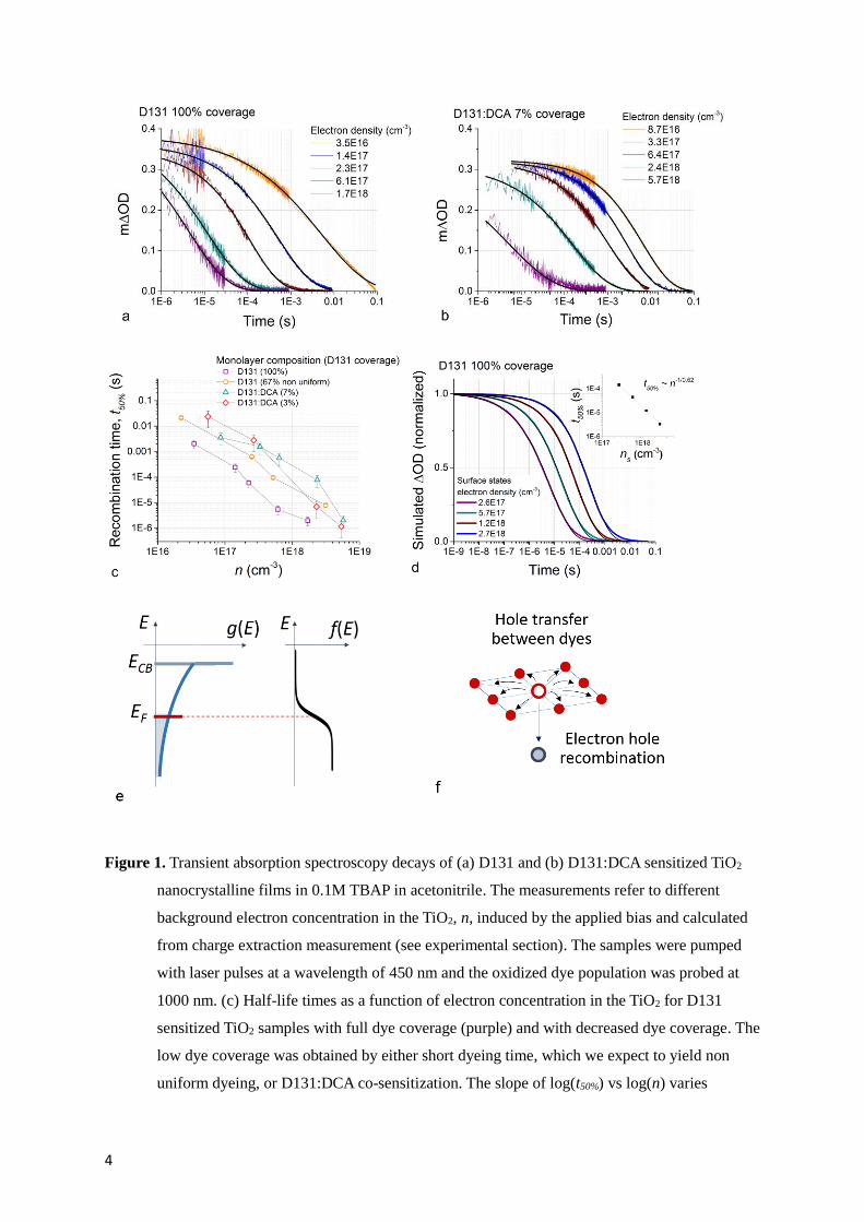
Figure 1a and b show transient measurements of oxidized dye absorption following 450 nm
wavelength laser pulse excitation of D131 sensitized TiO2 electrodes with different dye surface
coverage. The variation in transient optical density (ΔOD) reflects the population of oxidized dyes
remaining, probed at 1000 nm wavelength, and hence the dynamics of hole recombination with
electrons. The choice of wavelengths is discussed in Section 1 of the Supporting Information. Data are
plotted for different values of the background electron concentration in TiO2, n, controlled
electrochemically (see figure 1e) and measured via charge extraction. The measurements were
performed on the sample immersed in an inert electrolyte (0.1M tert-butyl ammonium perchlorate in
acetonitrile) in a three electrode cell as discussed in the experimental section. The lifetime of the holes
decreases substantially with increasing n in both cases of (a) high and (b) low D131 coverage,
consistent with previous reports.5 Figure 1c compares the half-life of the fully dyed D131 sensitized
sample with samples where the D131 loading was decreased either by using a short dyeing time or by
using the coadsorbent DCA to limit the uptake of the dye to the surface.25 The case of partial dye
desorption is also presented in Section 2 of the Supporting Information.
4
Figure 1. Transient absorption spectroscopy decays of (a) D131 and (b) D131:DCA sensitized TiO2
nanocrystalline films in 0.1M TBAP in acetonitrile. The measurements refer to different
background electron concentration in the TiO2, n, induced by the applied bias and calculated
from charge extraction measurement (see experimental section). The samples were pumped
with laser pulses at a wavelength of 450 nm and the oxidized dye population was probed at
1000 nm. (c) Half-life times as a function of electron concentration in the TiO2 for D131
sensitized TiO2 samples with full dye coverage (purple) and with decreased dye coverage. The
low dye coverage was obtained by either short dyeing time, which we expect to yield non
uniform dyeing, or D131:DCA co-sensitization. The slope of log(t50%) vs log(n) varies
5
between –(0.44)-1 and –(0.62)-1 for the different samples. The coverage fractions refer to D131
and were determined via dye desorption, as described in Section 3 of the Supporting
Information. Error bars were calculated based on the fractional variation in t50% of TAS decays
taken at open circuit before and after all the measurements. (d) Simulated hole recombination
in D131 monolayer with electrons situated on the surface of (20 nm)3 TiO2 particles. The
black lines correspond to stretched exponentials fitted to the simulations. (e) Schematics of
the density of states g(E) in TiO2 films and Fermi-Dirac distribution f(E) as a function of
electron energy. The position of the Fermi level EF determines the background electron
concentration n in the film. It is controlled with an applied bias in our experiments and it is an
input parameter in our calculations. (f) Model of recombination used for the calculations
displayed in figure 1d. Hole transfer between dyes competes with recombination with
electrons in the TiO2.
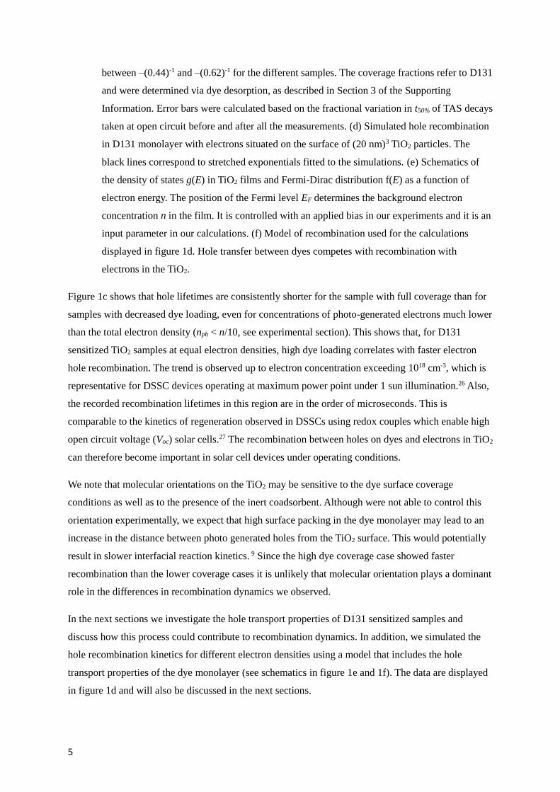
Figure 1c shows that hole lifetimes are consistently shorter for the sample with full coverage than for
samples with decreased dye loading, even for concentrations of photo-generated electrons much lower
than the total electron density (nph < n/10, see experimental section). This shows that, for D131
sensitized TiO2 samples at equal electron densities, high dye loading correlates with faster electron
hole recombination. The trend is observed up to electron concentration exceeding 1018 cm-3, which is
representative for DSSC devices operating at maximum power point under 1 sun illumination.26 Also,
the recorded recombination lifetimes in this region are in the order of microseconds. This is
comparable to the kinetics of regeneration observed in DSSCs using redox couples which enable high
open circuit voltage (Voc) solar cells.27 The recombination between holes on dyes and electrons in TiO2
can therefore become important in solar cell devices under operating conditions.
We note that molecular orientations on the TiO2 may be sensitive to the dye surface coverage
conditions as well as to the presence of the inert coadsorbent. Although were not able to control this
orientation experimentally, we expect that high surface packing in the dye monolayer may lead to an
increase in the distance between photo generated holes from the TiO2 surface. This would potentially
result in slower interfacial reaction kinetics. 9 Since the high dye coverage case showed faster
recombination than the lower coverage cases it is unlikely that molecular orientation plays a dominant
role in the differences in recombination dynamics we observed.
In the next sections we investigate the hole transport properties of D131 sensitized samples and
discuss how this process could contribute to recombination dynamics. In addition, we simulated the
hole recombination kinetics for different electron densities using a model that includes the hole
transport properties of the dye monolayer (see schematics in figure 1e and 1f). The data are displayed
in figure 1d and will also be discussed in the next sections.
6
Hole transport in the dye monolayer: interpreting transient anisotropy measurements
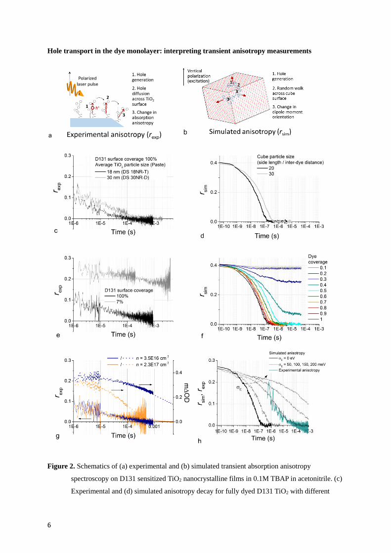
Figure 2. Schematics of (a) experimental and (b) simulated transient absorption anisotropy
spectroscopy on D131 sensitized TiO2 nanocrystalline films in 0.1M TBAP in acetonitrile. (c)
Experimental and (d) simulated anisotropy decay for fully dyed D131 TiO2 with different

7
TiO2 average particle size (diameter). (e) Anisotropy decay measured for films with full
(100%) D131 coverage and with partial (7%) D131 coverage obtained by co-sensitizing with
D131:DCA. The TAS decay for these samples is shown in figure 1a and b. (f) Simulated
coverage dependence of transient absorption anisotropy. (g) Anisotropy (left axis) and TAS
(right axis) decays measured for a fully dyed D131 TiO2 film with different electrochemically
induced electron concentrations in the TiO2 film (see legend). (h) Comparison between
experimental anisotropy and simulated anisotropy decays for the complete dye coverage case
including the effect of energetic disorder in the simulation (σE is the standard deviation of the
Gaussian distribution used to assign site energies). The simulated transient absorption
anisotropy decays refer to dyes arranged on the surface of a cube where each facet has 20×20
available sites. Values of electronic coupling J = 18 meV and reorganization energy λ = 1.062
eV were used in the model. For simulations displayed in (d) and (f) we considered the case of
transition dipole moments oriented perpendicular to the cube surface. Simulations shown in
(h) considers an angle of 152.6° between the unoxidized dye’s transition dipole moment
(oriented perpendicular to the surface) and oxidized dye’s transition dipole moment, based on
our TD-DFT analysis (see Section 1 and 4 in the Supporting Information).
In figure 2 we show measurements of transient absorption anisotropy under the same experimental
conditions as the data shown in figure 1 (0.1 M TBAP in acetonitrile). We also compare the
experimental observations to simulations of the transient absorption anisotropy profile of holes
diffusing in a dye monolayer arranged on the surface of a cubic particle (see experimental section).
Transient absorption anisotropy spectroscopy involves monitoring time resolved changes in
absorption anisotropy of the sample following pulsed polarized photo-excitation. The measurement
provides information on the transition dipole moment orientation of the photo-generated species, at a
specific probe wavelength, with respect to the excitation polarization. In the particular case of a dye
sensitized TiO2 nanoparticle, pumping the sample with polarized light selectively excites a population
of dyes whose transition dipole moments are aligned with the pump polarization at the excitation
wavelength. Electron injection in the TiO2 leaves these dyes in the oxidized state which present
different optical absorption features to the unoxidized molecule. Probing the changes in absorption
polarization (transition dipole moment orientation) of the oxidized dyes at a convenient wavelength
enables us to learn about the dynamics of photo-generated holes. In our case, the anisotropy probed at
1000 nm is expected to be dominated by the oxidized D131 component (see Section 1 of the
Supporting Information). Previous studies have discussed the relation between the transient
anisotropy profile of the oxidized dye absorption and the diffusion of the hole within the
monolayer.18,22 They concluded that decay in anisotropy can be interpreted in terms of holes being
transferred between dyes with different orientation. Changes in such orientation occur when the hole
is transferred to dyes that are anchored to sites of a particle with different surface orientations,
8
suggesting that experimental anisotropy decays could be directly interpreted in terms of distance
travelled by holes. For example, in the case of hole diffusion on a spherical surface where the dyes’
transition dipole moments are oriented perpendicular to the surface, anisotropy is expected to decay
mono-exponentially.18 On the other hand, neighboring dyes can present different orientation due to
different molecular configurations with respect to the surface, implying that evaluating the rate of
diffusion from transient anisotropy decays requires detailed knowledge of the system (see full
discussion in Section 4 of the Supporting Information). In figure 2c we compare the transient
anisotropy decay for mesoporous films made with different TiO2 particle sizes (18 versus 30 nm
diameter) both with full coverage of D131. This comparison shows that hole transport in dye
monolayers sensitizing larger size particles results in slower anisotropy decay dynamics. Assuming
that this correlation is causal, then this suggests that, for D131 on TiO2, photogenerated holes must
cover distances in the order of the particle size to obtain complete decay of this quantity. The
numerical model used for figure 2d and 2f considers dyes adsorbed on a cubic particle where dyes on
the same facet show identical transition dipole moments orientation. In this case, changes in
anisotropy only occur when the hole diffuses across a facet edge. Based on the above observation
about particle size dependence, the model should be at least in part representative of the real system.
Figure 2d compares the simulated decay in anisotropy for different size of the cubic particle,
reproducing qualitatively the difference in the profiles obtained for the experimental results. The
factors influencing the profile (amplitude, dispersion and timescale of the decay) of the simulated
anisotropy will be considered further below.
Figure 2e shows that, for a fully dyed sample, the transient anisotropy signal decays within few
hundreds of microseconds. On the other hand, when the D131 coverage is low, the transient
anisotropy signal at the earliest time resolved is about 0.25 and shows incomplete decay up to
millisecond timescale. The values of anisotropy recorded are lower than 0.4 which is the theoretical
maximum value for isotropic samples. 0.25 is likely to be the highest anisotropy achievable for this
dye, due to the relative orientation of the transition dipole moments that are involved in the excitation
of the dyes and probing of the oxidized dyes (more details can be found in Section 1 and 4 of the
Supporting Information). Slow decay in anisotropy is observed also for the other low coverage
samples (see Section 2 of the Supporting Information). These results are in qualitative agreement with
figure 2f where the simulated anisotropy profiles follow different dynamics depending on the surface
coverage. In particular for surface coverage < 50% incomplete decay is observed. This is consistent
with confinement of some holes on isolated islands of dyes on particular surface orientations of the
particles.
Figure 2g shows measurements of transient absorption anisotropy and the respective TAS decay on a
D131 sample while applying two different electrochemical potentials to the TiO2 electrode, which
result in different background electron concentrations measured by charge extraction. When

9
increasing the electron concentration by a factor of 6.5, the anisotropy decay shows no noticeable
difference even though the lifetime of the holes is significantly decreased (by a factor of 33). This
implies that electrons in the TiO2 do not significantly influence the rate of hole transport in the dye
monolayer. We therefore assume that, for all the traces displayed in figure 1a, hole diffusion kinetics
in the dye monolayer are the same.
The stretching shown for simulated transient absorption anisotropy of full coverage samples (figure
2d, f) is much less pronounced than the one observed experimentally (see figure 2c, e, g). From figure
2f, we note that dispersion increases slightly when less than 100% coverage is considered and
becomes important when approaching 40-50% coverage. Interconnection between sites occupied by
dyes becomes poor and hinders the diffusion of the charges across the particle’s surface. The
transition between the conditions of well and poorly interconnected network of dyes can be defined as
the percolation threshold. We conclude that local incomplete coverage may contribute to the observed
dynamics. In addition, other sources of dispersion in time constant are likely to play a role in
determining the stretched profile of the transient absorption anisotropy. In particular, we identify the
following main factors: disorder in dye site energies (figure 2h) and in relative spacing or interaction
between neighboring dyes; distribution in the relative orientation of the dyes’ transition dipole
moments; distribution in size and shape of the nanoparticles used experimentally (see full discussion
of these factors in Section 4 of the Supporting information). We also show that energetic disorder in
the monolayer results in an overestimate of the ‘apparent’ reorganization energy for intermolecular
charge transfer (see figure S7). This observation is expected for transport in disordered systems and
represents a potential explanation for the discrepancy between measured and calculated values of
reorganization energy in our earlier report.28
On the basis of these results and our previous investigations, our current interpretation of the hole
hopping process in the (D131) dye monolayer is as follows: hole transport between dyes anchored to
the surface of TiO2 particles occurs in samples with dye coverage exceeding the percolation threshold
and does not significantly depend on the electron density in the TiO2 scaffold. The stretched
anisotropy decays (figure 2) indicate pronounced dispersion in the transport of holes in the dye
monolayer across different surface orientations of the nanoparticle. This can be explained by
considering local incomplete coverage and/or energetic disorder between different sites. The latter
factor increases the apparent activation energy for transport. This can be extracted from temperature
dependent electrochemical measurements. Dye fluctuation may be responsible for the relatively high
hole diffusion coefficient and electronic coupling that we extract from cyclic voltammetry.29 Finally,
below the percolation threshold, diffusion of the holes on the surface is hindered due to the limited
number of connected paths formed by the dyes. This interpretation enables us to simulate electron
hole recombination accounting for hole diffusion properties of the dye monolayer as we discuss in the
next sections.
10
Electron-hole recombination and hole transport between dyes
We now consider the mechanism by which lateral hole transport described in the previous section and
figure 2 could influence the trend in recombination displayed in figure 1.
Our interpretation of the transient anisotropy measurements shown in this study suggests that the
trend of increasing hole lifetime with decreasing dye coverage seen in figure 1c can be explained in
terms of slower hole transport, i.e. inhibiting hole transport by reducing the dye surface coverage
correlates with decreased rate of electron-hole recombination. This implies that, in addition to electron
transport in the TiO2 and interfacial electron-hole reaction, the dynamics of hole transport could be
contributing to the observed kinetics of the decay in photogenerated hole population measured with
TAS.
The relation between charge transport properties and recombination kinetics in a system depends on
the dimensionality of the phases populated by the charges and on the type of ‘interface’ between such
phases where recombination occurs. For example, when electrons and holes share the same phase, the
recombination rate constant is expected to depend on the sum of the charge mobilities (Langevin
recombination). Conversely, when electrons and holes are transported in two separate phases and need
to reach an interface in order for recombination to occur, then the rate of collision of electrons with
holes is limited by the slowest charge carrier’s mobility.30 Recombination between electrons in
nanoparticles and holes in the dye monolayer adsorbed to the nanoparticle represents another type of
system where one of the charge carriers (holes) is permanently exposed to the recombination
interface, while the other (electrons) is not.
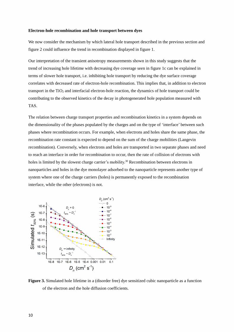
Figure 3. Simulated hole lifetime in a (disorder free) dye sensitized cubic nanoparticle as a function
of the electron and the hole diffusion coefficients.

11
Figure 3 shows the simulated dependence of hole lifetime on the electron and hole diffusion
coefficients for the case of a cubic particle populated with one hole (diffusing on the surface of the
cube) and one electron (diffusing within the volume of the cube). For this simulation we considered
the case of recombination being limited by collision of the two charges, hence charges recombine
when they approach each other within a certain distance (in this case, √3 times the lattice parameter).
We can identify three regimes in the recombination kinetics of this system. First, when hole transport
in the monolayer is slower than electron transport in the bulk of the particle, recombination is limited
by electron diffusion to the interface and to the site where the hole is localized. As a results, t50% is
proportional to Dn-1, as it is also expected for the case of immobile holes (Dp = 0). When holes move
significantly faster in the dye monolayer than electrons within the particle, the recombination time
approaches the time that it takes for the electron to diffuse to any site at the interface (since the time
taken by the hole to explore the whole particle surface is comparatively negligible). This regime also
shows a t50% ~ Dn-1 behavior. In the intermediate regime the hole diffusion coefficient is equal or
greater by only few orders of magnitude than the electron diffusion coefficient and the recombination
lifetime is dependent on both these quantities.
However, the condition Dp > Dn is not expected for the case of data presented in figure 1a, b and c, at
least for the high electron density conditions, therefore this model cannot quantitatively explain our
experimental observation. We note that a more complete model is needed to account for the disorder
in the TiO2 and in the dye monolayer, which is expected to influence these regimes of electron hole
recombination. We address this factor in the next section.
The effect of disorder on recombination
The effect of energetic disorder and dispersive electron transport in mesoporous TiO2 on the stretched
electron-hole recombination kinetics and electron density dependence of holes lifetime has been
extensively investigated (see introduction). Below, we discuss the possibility that dispersive transport
in the dye monolayer could also contribute to experimental observations of stretched recombination
kinetics.
In order to explore this hypothesis, we consider a simplified model for the recombination process
where electron transport within the TiO2 particle is not a rate limiting factor. We focus instead on the
effect of hole transport and disorder in the dye monolayer on the simulated recombination kinetics.
We find that energetic disorder in the dye monolayer combined with inhomogeneity in the TiO2
surface reactivity can introduce significant dispersion in the hole population decay as well as electron
density dependence of the hole lifetime which deviates from a first order reaction (t50% ~ n-1). We note
that inhomogeneity in surface reactivity of anatase TiO2 nanoparticles is expected, and has been
shown previously.31 In our model we consider energetic disorder for the TiO2 surface states as a
12
source of such inhomogeneity. In figure 1d we show the simulated results of electron hole
recombination given the model described in the experimental section and in detail in Section 5 of the
Supporting Information. These simulations refer to the same hole transport parameters used for the
data in figure 2h (for σE = 100 meV) while the energetic disorder in the TiO2 surface is obtained by
assigning electronic energy levels drawn from an exponential density of states for each of the cubic
particle’s surface sites. In the model, the energetic disorder for the surface sites in the TiO2 affects the
hole recombination rate to each site, which is calculated to be proportional to the TiO2 electronic site
occupancy, given the Fermi level position used in the simulation. The surface site energies and the
energetic disorder in the dye monolayer used in our model are uncorrelated. Figure 1d (along with
figure S9) shows that the model produces results: with a similar timescale and dispersion to the data
displayed in figure 1a for the transient absorption measurement of electron-hole recombination; and
with a charge density dependence of the half-life which reproduces the experimental observation. In
particular, figure S9 and table S1 of the Supporting Information illustrate that both disorder in the
monolayer and in the TiO2 surface reactivity have to be present in order to observe these effects. In
the model we have focussed on the case of energetic disorder for both hole transport and the TiO2
surface, however we would potentially expect an analogous trend to result from other sources of
disorder.
The only free parameters in the model are the charge transfer rate between electronic states in the
TiO2 and oxidized dyes and the position of the conduction band edge. We discuss the sensitivity of the
model to these quantities in Section 5 of the Supporting Information. The model reproduces the
pronounced deceleration in recombination kinetics when the dye surface coverage is reduced below
the percolation threshold observed experimentally.
Hole transport between dyes and electron-hole recombination: the effect of the solvent
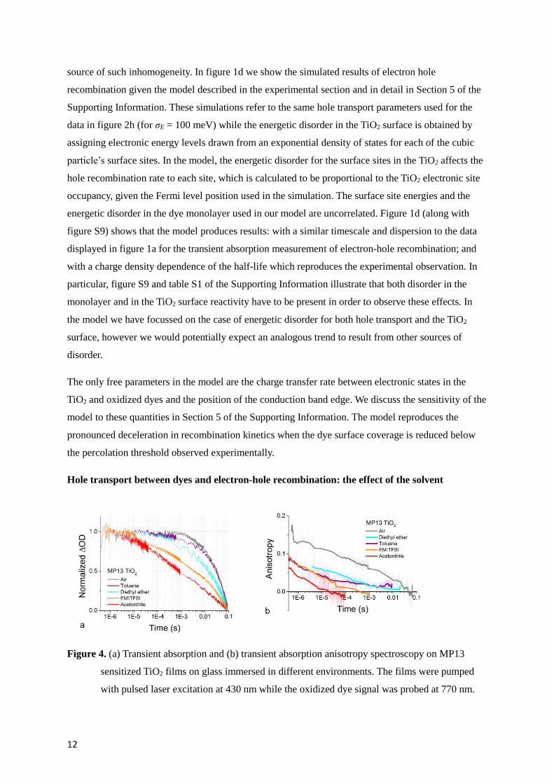
Figure 4. (a) Transient absorption and (b) transient absorption anisotropy spectroscopy on MP13
sensitized TiO2 films on glass immersed in different environments. The films were pumped
with pulsed laser excitation at 430 nm while the oxidized dye signal was probed at 770 nm.
13
The solid lines in (b) are obtained by calculating a moving average of the raw data (also
displayed in background).
To further investigate the correlation between hole transport in the dye monolayer and electron hole
recombination, we measured samples consisting of nominally identical MP13 sensitized TiO2 films
(with 100% dye surface coverage) exposed to different solvent environments. MP13 was chosen as it
shows lower degree of desorption when immersed in the solvents investigated and better photo-
stability than D131. Figure 4 shows the TAS and the transient absorption anisotropy decays for holes
in MP13 sensitized TiO2 films immersed in 4 different solvents and air. Both the dynamics of electron
hole recombination and of hole diffusion undergo a remarkable change when changing the
environment. Comparison of the recombination and the transient anisotropy decays between
measurements shows that fast anisotropy decay, hence fast hole transport in the dye monolayer,
correlates with fast electron hole recombination. One possible explanation for this set of data is
therefore that the ability of holes to move on the surface of the particle catalyzes the recombination
with electrons in the TiO2. This would be consistent with our interpretation of the results displayed in
figure 1c.
We note that the extent to which the transient anisotropy varies when holes hop between neighbouring
molecules depends on the relative configuration of the molecules (see Section 4 of the Supporting
Information). For this reason, a direct and quantitative comparison of the anisotropy decays in figure
4b may not be reliable at this level of description. For the scope of this paper, the comparison of the
decay timescales for the different solvent systems is still informative if we simply view the different
solvents as a means to empirically change the hole transport rate.
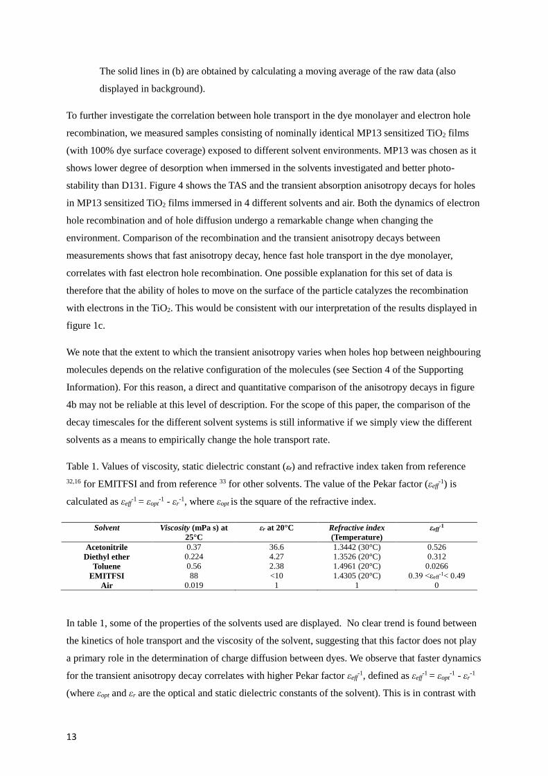
Table 1. Values of viscosity, static dielectric constant (εr) and refractive index taken from reference
32,16 for EMITFSI and from reference 33 for other solvents. The value of the Pekar factor (εeff-1) is
calculated as εeff-1 = εopt
-1 - εr-1, where εopt
is the square of the refractive index.
Solvent Viscosity (mPa s) at
25°C
εr at 20°C Refractive index
(Temperature)
εeff-1
Acetonitrile 0.37 36.6 1.3442 (30°C) 0.526 Diethyl ether 0.224 4.27 1.3526 (20°C) 0.312
Toluene 0.56 2.38 1.4961 (20°C) 0.0266 EMITFSI 88 <10 1.4305 (20°C) 0.39 <εeff
-1< 0.49 Air 0.019 1 1 0
In table 1, some of the properties of the solvents used are displayed. No clear trend is found between
the kinetics of hole transport and the viscosity of the solvent, suggesting that this factor does not play
a primary role in the determination of charge diffusion between dyes. We observe that faster dynamics
for the transient anisotropy decay correlates with higher Pekar factor εeff-1, defined as εeff
-1 = εopt-1 - εr
-1
(where εopt and εr are the optical and static dielectric constants of the solvent). This is in contrast with
14
what would be expected for inter-dye hole transfer in a solvent environment within the non-adiabatic
Marcus theory. When the environment is treated as a continuous medium, the outer sphere
reorganization energy for charge transfer is proportional to the Pekar factor, implying that for
environments showing high Pekar factors a slower transfer rate would be expected.18,23 A similar trend
was observed for estimates of the hole diffusion coefficient in dye sensitized oxide films from
electrochemical measurements where ions are present in electrolytes. The diffusion coefficient was
found to increase using solvents with increasing polarity.16 The results were explained in terms of
faster charge compensation by the ions in polar solvents upon inter-dye hole transfer where ion
pairing is less pronounced than in non-polar solvents. In our experiments, the same trend is found in
absence of electrolyte ions, ruling out the role of ionic charge compensation as a limiting step for
charge transport for our system. This observation questions the validity of predicting charge transfer
rates in these weakly coupled systems on the basis of the expected outer sphere reorganization
energies according to non-adiabatic Marcus’ theory. Considering the surrounding solvent as a
dielectric continuum may represent one key limitation. We also note that the reorganization energy is
not the only parameter which is affected by the surrounding medium. Different solvents may
influence the configuration of the molecules on the surface, thus influencing the transport rate. In
particular, the coupling between dyes is highly sensitive to the packing of the monolayer and eventual
change in order. One possibility is that the use of polar solvent results in more favourable
configurations of the dyes for charge transport. The change in the electrostatic environment could also
vary the energetic disorder in the monolayer.
The different solvents used here are expected to result in different outer sphere reorganization energies
of charge transfer between dyes, but also different outer sphere reorganization energies for the
electron transfer from TiO2 to oxidized dyes. Assuming that the latter process occurs in the Marcus
inverted region, higher reorganization energy would result in faster rates of charge transfer.34,35 The
results shown in figure 4a could therefore also be interpreted on the basis of increasing Pekar factor
resulting in faster recombination reaction upon electron hole encounter. This interpretation assumes
that the electron transfer reaction between TiO2 and the dyes is the limiting factor to the rate of
recombination, as opposed to the electron transport to the dye-TiO2 interface. On a related note, the
solvent surrounding the sensitized film is expected to vary the oxidation potential of the dye. This
influences the difference in free energy describing the charge recombination reaction and ultimately
its rate. We note that a complete model describing recombination in dye-TiO2 systems as a Marcus’
inverted region reaction is still missing.36,37 In addition to these factors, the use of different solvents
may vary the TiO2 density of states and mobility of electrons in the film. This effect could also
contribute to the observed trend.
In a previous report by Bonhôte et al., hole transport through the dye monolayer to the FTO contact in
DSSCs was considered as a possible route for faster electron-hole recombination.11 In our study
15
correlation between hole transport and hole lifetime is observed for samples fabricated on glass
substrates or including a TiO2 compact layer covering the FTO contact indicating that hole transfer to
electrons in FTO does not contribute to observed trend in recombination kinetics.
Conclusions
We have shown experimental evidence that hole transport in high coverage dye layers anchored to the
TiO2 nanoparticles increases the rate of recombination of photo-generated holes with electrons in the
oxide. We demonstrated that reducing the rate of recombination (and the rate of hole transport) can be
achieved by either reducing the dye surface coverage or by using solvents showing low Pekar factor.
Using Monte Carlo simulations we identified three kinetic regimes of recombination for a cubic
particle depending on the relative magnitude of electron and hole diffusion coefficients. The
measurements of hole diffusion in the dye monolayer via transient anisotropy spectroscopy suggests
that this process is highly dispersive. We simulated the transient anisotropy signal and electron hole
recombination using model inputs based on our previous electrochemical and computational
investigations of hole hopping between dyes. The observed dispersive character of hole transport can
be explained by considering the effect of disorder and incomplete coverage in the monolayer. We also
showed that dispersive hole transport, combined with spatial inhomogeneity in interfacial
recombination with electrons in the TiO2, contributes to the dispersion in the hole population decay
observed with transient absorption measurements and to the electron density dependence of hole
lifetime. The significant increase in the lifetime of photo-generated charges that we induced by
reducing dye coverage or using solvents with low Pekar factor has important implications for both
DSSCs architectures where electron recombination with oxidized dyes limits their Voc, and solar fuel
devices where surface adsorbates catalyze slow chemical reactions. Together with our previous
reports, this study emphasizes the importance of characterizing recombination of photo-generated
charges in molecular sensitized mesoporous films in conjunction with the investigation of the charge
transport properties of the dye layer. These insights suggest approaches to control intermolecular
lateral processes, as opposed to other interfacial properties, as a route to improve device performance.
We have also shown that studying lateral transport in dye monolayers is a useful strategy to test the
validity of electron transfer theories adopted to model charge transfer events in these systems. Our
data show that the solvent dependence of hole transport between dyes cannot be explained on the
basis of the expected variation in reorganization energy of charge transfer and the use of non-adiabatic
Marcus theory.
Experimental section
Sample preparation and spectroscopy measurements were carried out using the setup and methods
described in references 28,38 and 22. These can be found in Section 3 of the Supporting Information.
16
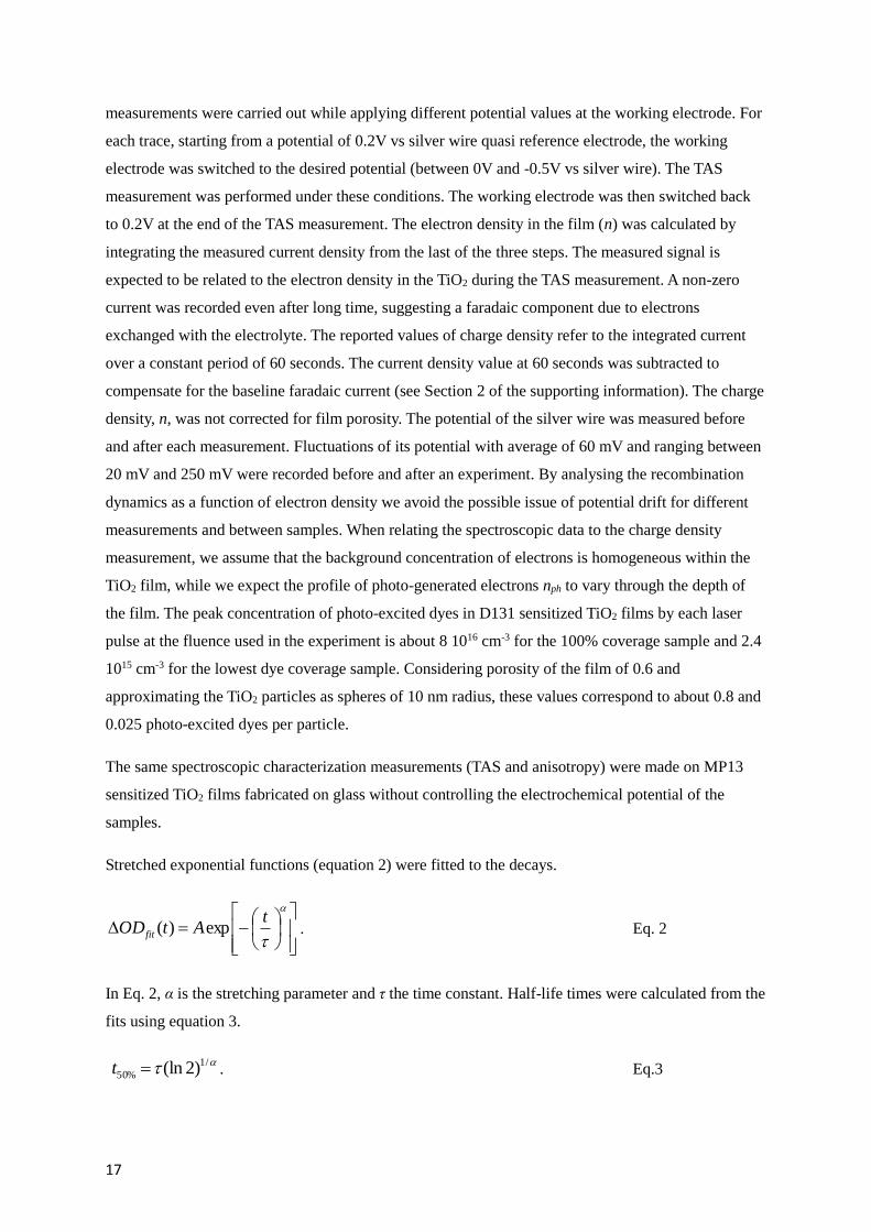
The transient anisotropy rexp(t) was calculated from the measurements of transient optical density for
vertical and horizontal polarization of the probe beam (ΔODV(t) and ΔODH(t) respectively), following
a vertically polarized optical pump pulse, as:
)(2)(
)()()(exp
tODtOD
tODtODtr
HV
HV
eq. 1
For all the anisotropy measurements shown in this study, ΔODV has been calculated as the average of
a measurement taken before and after the measurement of ΔODH , to approximately compensate for
any degradation of the film. This was significant for some of the samples as we show in Section 6 of
the Supporting Information. TAS and transient anisotropy measurements were performed on D131
(purchased from Mitsubishi paper mills limited) and MP13 (chemical synthesis is illustrated in
Section 7 of the Supporting Information) sensitized TiO2. Samples with incomplete D131 coverage
were fabricated by either adopting short dyeing time or by using the inert coadsorbent
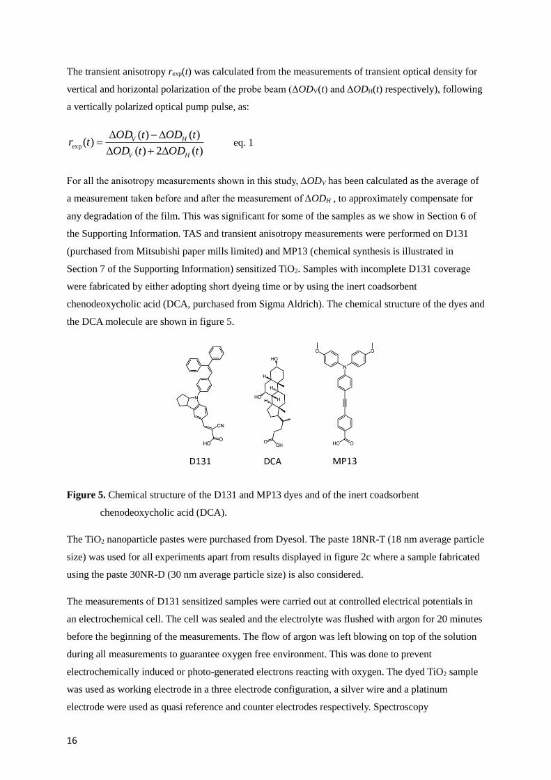
chenodeoxycholic acid (DCA, purchased from Sigma Aldrich). The chemical structure of the dyes and
the DCA molecule are shown in figure 5.
Figure 5. Chemical structure of the D131 and MP13 dyes and of the inert coadsorbent
chenodeoxycholic acid (DCA).
The TiO2 nanoparticle pastes were purchased from Dyesol. The paste 18NR-T (18 nm average particle
size) was used for all experiments apart from results displayed in figure 2c where a sample fabricated
using the paste 30NR-D (30 nm average particle size) is also considered.
The measurements of D131 sensitized samples were carried out at controlled electrical potentials in
an electrochemical cell. The cell was sealed and the electrolyte was flushed with argon for 20 minutes
before the beginning of the measurements. The flow of argon was left blowing on top of the solution
during all measurements to guarantee oxygen free environment. This was done to prevent
electrochemically induced or photo-generated electrons reacting with oxygen. The dyed TiO2 sample
was used as working electrode in a three electrode configuration, a silver wire and a platinum
electrode were used as quasi reference and counter electrodes respectively. Spectroscopy
17
measurements were carried out while applying different potential values at the working electrode. For
each trace, starting from a potential of 0.2V vs silver wire quasi reference electrode, the working
electrode was switched to the desired potential (between 0V and -0.5V vs silver wire). The TAS
measurement was performed under these conditions. The working electrode was then switched back
to 0.2V at the end of the TAS measurement. The electron density in the film (n) was calculated by
integrating the measured current density from the last of the three steps. The measured signal is
expected to be related to the electron density in the TiO2 during the TAS measurement. A non-zero
current was recorded even after long time, suggesting a faradaic component due to electrons
exchanged with the electrolyte. The reported values of charge density refer to the integrated current
over a constant period of 60 seconds. The current density value at 60 seconds was subtracted to
compensate for the baseline faradaic current (see Section 2 of the supporting information). The charge
density, n, was not corrected for film porosity. The potential of the silver wire was measured before
and after each measurement. Fluctuations of its potential with average of 60 mV and ranging between
20 mV and 250 mV were recorded before and after an experiment. By analysing the recombination
dynamics as a function of electron density we avoid the possible issue of potential drift for different
measurements and between samples. When relating the spectroscopic data to the charge density
measurement, we assume that the background concentration of electrons is homogeneous within the
TiO2 film, while we expect the profile of photo-generated electrons nph to vary through the depth of
the film. The peak concentration of photo-excited dyes in D131 sensitized TiO2 films by each laser
pulse at the fluence used in the experiment is about 8 1016 cm-3 for the 100% coverage sample and 2.4
1015 cm-3 for the lowest dye coverage sample. Considering porosity of the film of 0.6 and
approximating the TiO2 particles as spheres of 10 nm radius, these values correspond to about 0.8 and
0.025 photo-excited dyes per particle.
The same spectroscopic characterization measurements (TAS and anisotropy) were made on MP13
sensitized TiO2 films fabricated on glass without controlling the electrochemical potential of the
samples.
Stretched exponential functions (equation 2) were fitted to the decays.
tAtODfit exp)( . Eq. 2
In Eq. 2, α is the stretching parameter and τ the time constant. Half-life times were calculated from the
fits using equation 3.
/1
%50 )2(lnt . Eq.3

18
For most MP13 samples a background concentration of holes was present during the TAS
measurements. This implies that half-life times for the incomplete decays would be longer than the
ones that would be extracted from the data presented. Since the accumulation of background charges
speeds up otherwise very slow recombination dynamics, this does not vary the relative trend of the
kinetics observed between different measurements.
Monte Carlo simulations: simulations of transient absorption anisotropy were carried out considering
a square lattice of sites (dye monolayer) on the surface of a cube (TiO2 nanocrystal). The data
presented in the results section correspond to simulations of hole transfer between D131 dyes on the
surface of a cubic TiO2 particle of 203 nm3 in size. Inter-dye distance was approximated to 1 nm. In
the model, one hole at a time is considered per simulated experiment. The hole can be exchanged only
between sites occupied by dyes and between up to 8 nearest neighbours. The kinetics of hole transfer
between available sites are calculated using adaptive waiting times, which is expressed as a function
of the non-adiabatic Marcus’ charge transfer rate (see Section 3 in the Supporting Information). The
reorganization energy of charge transfer was calculated as reported in a previous study, and the case of
0.1M ions in acetonitrile was considered to match the experimental conditions.39 In the disorder free
case, the electronic coupling was taken from the experimental estimate reported in reference 28 (see
Section 3 of the Supporting Information for more details). To introduce configurational disorder in the
dye monolayer, a Gaussian distribution of calculated electronic couplings between sites was used (the
distribution was for log J). Similarly, a Gaussian distribution of calculated site energy differences was
implemented to simulate energetic disorder in the monolayer.
In order to simulate the transient absorption anisotropy profile expected for photogenerated holes
diffusing in the dye monolayer, assumptions on the orientation of the transition dipole moments of the
dye have to be taken. Calculations presented in figure 2d, 2f consider the simplified case where the
neutral state and oxidized state transition dipole moments are parallel. Under these conditions, our
simulated profiles show initial values of 0.4, which is the maximum value expected for anisotropy
measurement in isotropic systems. The transient anisotropy profile describes the change in orientation
of the transition dipole moment of the oxidized dyes population in time. Therefore, the distribution of
transition dipole moment orientations for the oxidized dyes on the surface of the particle influences
the dynamics of the transient anisotropy decay. By considering all dipoles to be perpendicular to the
surface of the particle, changes in anisotropy for each random walk experiment are recorded only
upon hole exchange between different facets. Figure 2h refer to calculations where the relative
orientation of the unoxidized and oxidized D131 dyes are take into account (see TD-DFT calcualtions
in Section 1 of the Supporting Information). For this case, the unoxidized transition dipole moment is
still set to be perpendicular to the cube surface, while the oxidized D131 dipoles are oriented at 152.6°
from the normal. A rotation about the normal by a random angle is also applied to these dipoles for all
dyes at the beginning of all random walk experiments. We discuss these and other aspects of

19
accounting for transition dipole moment and dye backbone orientation in in Section 4 of the
Supporting Information.
The facet where the hole was placed at t = 0 for each experiment was picked on the basis of a
probability proportional to cos2ϑ, where ϑ is the angle between the polarization axis of the excitation
and the normal vector to the facet’s surface. When running the random walk experiment, the square
projection of the dipole moment of the oxidized dye in the direction parallel and in one of the
directions perpendicular to the polarization axis were recorded. These quantities were averaged over
time for all experiments and finally used to calculate the simulated anisotropy decay using eq. 1. The
random walk was ended after a certain time. This was the same for all experiments in a simulation.
Each experiment takes into account a different orientation of the cubic particle with reference to the
polarization axis of the excitation which was instead kept constant. Each simulated anisotropy profile
presented here represents the average of 104 experiments.
Simulation of electron hole recombination dynamics shown in figure 1d and in Section 5 of the
Supporting Information were carried out using a model that considers one surface electronic state for
the TiO2 associated to each dye site. The energy of each state is drawn from an exponential
distribution based on experimental observation (see charge extraction measurements in Section 2 of
the supporting information). All states share the same quasi Fermi level, i.e. we consider electron
transport in the TiO2 to be significantly faster than hole transport in the dye monolayer and electron-
hole recombination, such that all electronic states are in quasi equilibrium. The rate of electron
transfer (recombination) from a TiO2 surface electronic state to a hole located on the site associated to
that specific state was evaluated as the product of a fixed rate and the Fermi-Dirac probability of
occupancy of the electronic state. Such rate was used in the calculation of the waiting time for hole
hopping as an additional ‘competing’ charge transfer route during hole diffusion. This effectively
introduces different recombination rates for different position of the holes on the surface of the
particle. The electronic energies of the electron surface states and the energies of the dye sites used for
hole hopping between neighbouring dyes were recalculated at the beginning of each experiment.
Simulations of electron-hole recombination shown in figure 3 were carried out considering a cubic
particle as described above where electrons can diffuse in the bulk of the particle and holes can
diffuse on the surface of the particle. Given the input values of the electron and hole diffusion
coefficients (Dn, Dp), constant charge transfer rates for electrons and holes were calculated using the
relations kn = 6 Dn/a2 and kp = 4 Dp/a2, where a is the lattice spacing. The same value of lattice
parameter a was used for the bulk (electron diffusion) and the surface of the particle (hole diffusion).
Charges could be exchanged between 6 (for electrons) and 4 (for holes) nearest neighbours. The
electron and the hole’s positions were initially defined randomly within their respective spaces.
Recombination times between charges was recorded once the electron and the hole were at a distance

20
equal or lower than 31/2a. We ran 103 experiments for each condition and we extracted the lifetime
(t50%) from the resulting population decay.
Associated content
Supporting Information:
TD-DFT calculations and spectroelectrochemical measurement on D131 dye; bias dependent TAS
measurements on D131 sensitized TiO2 films; additional details on experimental and computational
method; analysis of dispersion in transient absorption anisotropy decays; simulation of electron hole
recombination; dye degradation; MP13 synthesis and properties.
Acknowledgements
We thank Xiaoe Li, Shogo Mori and Shane Ardo for useful discussions. DM and PB are grateful for
EPSRC fellowship EP/J002305/1. NR thanks EPRSC for grant number EP/H040218/1.
References
(1) O’Regan, B.; Moser, J.; Anderson, M.; Graetzel, M. J. Phys. Chem. 1990, 94 (24), 8720.
(2) Tachibana, Y.; Vayssieres, L.; Durrant, J. R. Nat. Photonics 2012, 6 (8), 511.
(3) Hagfeldt, A.; Boschloo, G.; Sun, L.; Kloo, L.; Pettersson, H. Chem. Rev. 2010, 110 (11), 6595.
(4) Ardo, S.; Meyer, G. J. Chem. Soc. Rev. 2009, 38 (1), 115.
(5) Haque, S. A.; Tachibana, Y.; Klug, D. R.; Durrant, J. R. J. Phys. Chem. B 1998, 102 (10), 1745.
(6) Nelson, J.; Haque, S.; Klug, D.; Durrant, J. Phys. Rev. B 2001, 63 (20), 1.
(7) Nelson, J. Phys. Rev. B 1999, 59 (23), 374.
(8) Clifford, J. N.; Yahioglu, G.; Milgrom, L. R.; Durrant, J. R. Chem. Commun. 2002, 1260.
(9) Clifford, J. N.; Palomares, E.; Nazeeruddin, M. K.; Grätzel, M.; Nelson, J.; Li, X.; Long, N. J.;
Durrant, J. R. J. Am. Chem. Soc. 2004, 126 (16), 5225.
(10) Johansson, P. G.; Kopecky, A.; Galoppini, E.; Meyer, G. J. J. Am. Chem. Soc. 2013, 135 (22),
8331.
(11) Bonhôte, P.; Moser, J. E.; Humphry-Baker, R.; Vlachopoulos, N.; Zakeeruddin, S. M.; Walder,
L.; Grätzel, M. J. Am. Chem. Soc. 1999, 121 (6), 1324.
(12) Palomares, E.; Clifford, J. N.; Haque, S. a; Lutz, T.; Durrant, J. R. J. Am. Chem. Soc. 2003, 125
(2), 475.
(13) Wenger, B.; Bauer, C.; Nazeeruddin, M. K.; Comte, P.; Zakeeruddin, S. M.; Gratzel, M.;
Moser, J.-E. Proc. SPIE 2006, 6325, 1.
(14) Hasselmann, G. M.; Meyer, G. J. J. Phys. Chem. B 1999, 103 (36), 7675.
(15) Wang, D.; Mendelsohn, R.; Galoppini, E.; Hoertz, P. G.; Carlisle, R. a; Meyer, G. J. J. Phys.
Chem. B 2004, 108 (42), 16642.
(16) Bonhôte, P.; Gogniat, E.; Tingry, S.; Barbe, C.; Vlachopoulos, N.; Lenzmann, F.; Comte, P.;
Gratzel, M. J. Phys. Chem. B 1998, 5647 (97), 1498.
21
(17) Hu, K.; Meyer, G. J. Langmuir 2015, 31 (41), 11164.
(18) Ardo, S.; Meyer, G. J. J. Am. Chem. Soc. 2011, 133 (39), 15384.
(19) Brennan, B. J.; Durrell, A. C.; Koepf, M.; Crabtree, R. H.; Brudvig, G. W. Phys. Chem. Chem.
Phys. 2015, 17, 12728.
(20) Wang, Q.; Evans, N.; Zakeeruddin, S. M.; Exnar, I.; Grätzel, M. J. Am. Chem. Soc. 2007, 129
(11), 3163.
(21) Wang, Q.; Zakeeruddin, S. M.; Cremer, J.; Bäuerle, P.; Humphry-Baker, R.; Grätzel, M. J. Am.
Chem. Soc. 2005, 127 (15), 5706.
(22) Moia, D.; Cappel, U. B.; Leijtens, T.; Li, X.; Telford, A. M.; Snaith, H. J.; O’Regan, B. C.;
Nelson, J.; Barnes, P. R. F. J. Phys. Chem. C 2015, 33 (119), 18975.
(23) Moia, D.; Leijtens, T.; Noel, N.; Snaith, H. J.; Nelson, J.; Barnes, P. R. F. Adv. Mater. 2015, 27
(39), 5889.
(24) Ogawa, J.; Koumura, N.; Hara, K.; Mori, S. Jpn. J. Appl. Phys. 2014, 53, 1.
(25) O’Regan, B.; Li, X.; Ghaddar, T. Energy Environ. Sci. 2012, 5 (5), 7203.
(26) Barnes, P. R. F.; Miettunen, K.; Li, X.; Anderson, A. Y.; Bessho, T.; Gratzel, M.; O’Regan, B.
C. Adv. Mater. 2013, 25 (13), 1881.
(27) Yang, W.; Vlachopoulos, N.; Hao, Y.; Hagfeldt, A.; Boschloo, G. Phys. Chem. Chem. Phys.
2015, 17, 15868.
(28) Moia, D.; Vaissier, V.; López-Duarte, I.; Torres, T.; Nazeeruddin, M. K.; O’Regan, B. C.;
Nelson, J.; Barnes, P. R. F. Chem. Sci. 2014, 5 (1), 281.
(29) Vaissier, V.; Mosconi, E.; Moia, D.; Pastore, M.; Frost, J. M.; De Angelis, F.; Barnes, P. R. F.;
Nelson, J. Chem. Mater. 2014, 26 (16), 4731.
(30) Koster, L. J. a; Mihailetchi, V. D.; Blom, P. W. M. Appl. Phys. Lett. 2006, 88 (5), 1.
(31) Gottesman, R.; Tirosh, S.; Barad, H.; Zaban, A. J. Phys. Chem. Lett. 2013, 17 (4), 2822.
(32) Bonhôte, P.; Dias, A.-P.; Armand, M.; Papageorgiou, N.; Kalyanasundaram, K.; Grätzel, M.
Inorg. Chem. 1996, 35 (5), 1168.
(33) Lide, D. R. CRC Handbook of Chemistry and Physics, Internet V.; CRC Press, Boca Raton,
FL, 2005.
(34) Gould, I. R.; Ege, D.; Moser, J. E.; Farid, S. J. Am. Chem. Soc. 1990, 11 (112), 4290.
(35) Dang, X.; Hupp, J. T. J. Am. Chem. Soc. 1999, 36 (121), 8399.
(36) Moser, J. E.; Gratzel, M. Chem. Phys. 1993, 176 (2-3), 493.
(37) Yan, S. G.; Prieskorn, J. S.; Kim, Y.; Hupp, J. T. J. Phys. Chem. B 2000, 46 (104), 10871.
(38) Anderson, A. Y.; Barnes, P. R. F.; Durrant, J. R.; O’Regan, B. C. J. Phys. Chem. C 2011, 115
(5), 2439.
(39) Vaissier, V.; Barnes, P.; Kirkpatrick, J.; Nelson, J. Phys. Chem. Chem. Phys. 2013, 15 (13),
4804.