ecf range ultra violet disinfection systemceswaterquality.com/files/ecf ii i-o.pdfecf range ultra...
TRANSCRIPT

Installation & Operation Manual V2.32
ECF Range Ultra Violet Disinfection System
Distributed by Manufactured by Engineered Treatment Systems atg-willand W9684 Beaverland Parkway Wigan Beaver Dam England Wisconsin www.atgwilland.com United States of America Telephone 920 885 4628 Facsimile 920 885 4386 Email [email protected] Jeff Cell 920-382-5315

Section-1 Health & Safety
Page 2 of 28

Page 1 of 28
CONTENTS Section- 1 Health & Safety Page 1.1 Personnel 2 1.2 Quartz Components 1.3 Ultra Violet Lamps 1.4 Operating Temperature 1.5 Electrical Isolation 1.6 Electrical Earthing Section-2 Installation Page 2.1 The UV Chamber 3 2.2 Electrical Connections 2.3 UV Intensity Monitor 2.4 Temperature Sensor Section-3 Control & Operation Page 3.1 Display Layout 5 3.2 Basic Operation 3.3 Keypad Operation 3.4 Main Screens 3.5 Priority Screens 3.6 Operator Screens 3.7 Engineering Screens Section-4 Calibration Page 4.1 Calibration of the UV Intensity Monitor 19 Section-5 Replacements Page 5.1 Replacing the UV Lamp 21 5.2 Replacing the Quartz Sleeve 5.3 Replacing the Quartz Window Section-6 Maintenance Schedule Page 6.1 Maintenance Log 24 6.2 Performance Monitoring 6.3 UV Lamp 6.4 Quartz Cleaning & Replacement 6.5 Seals 6.6 Control panel Section-7 Fault Finding Page 7.1 UV Disinfection System Trips on Lamp Fault 26 7.2 UV Disinfection System Trips on Low UV Appendix Page Recommended Spares 27 K intensity , K time values 28 Maintenance log sheet 29 This document contains confidential and proprietary information regarding atg-willand equipment. Upon receipt of this document the recipient agrees not to reproduce, copy or transmit any portion of information contained therein, in whole, in part, or permit such action by others for any purpose, without prior written permission being first obtained from atg-willand.
Section-1 Health & Safety
Page 2 of 28
1 Health & Safety 1.1 Personnel To ensure safety, all personnel involved with the maintenance and operation of the UV system should read this manual. Only suitably qualified personnel should be employed to carry out the operation and maintenance of the unit. 1.2 Quartz Components The quartz components should be handled with extreme care. Avoid touching the quartz components with bare hands as fingerprints can impair the effectiveness of the unit. The components should only be handled with lint free or rubber gloves. If the surface of the quartz components become contaminated they must be cleaned thoroughly before use. Quartz components have a high transmission value to short wave Ultra Violet radiation. 1.3 Ultra Violet Lamps The UV lamps emit short wave radiation which can be damaging to eyes and skin. At no time should personnel be exposed to this radiation. Under no circumstance should the lamp be operated outside the chamber. The system must be switched off and isolated before removing the safety cover at the ends of the chamber or removing the UV intensity monitor. The UV lamps contain a small quantity of mercury. They should be stored and handled with great care to avoid damage. All used lamps should be disposed of correctly. If in doubt please contact your supplier. 1.4 Operating Temperature Medium pressure UV lamps operate at very high temperatures (around 7000C). Extreme care should be taken when handling the UV lamp and other components from the chamber after the system has been in operation. Allow a sufficient period of time (at least 10 minutes) for the lamp to cool down before attempting to remove. 1.5 Electrical Isolation This unit operates under high voltage conditions and must be electrically isolated before general maintenance is carried out. The mains isolator is located on the control panel and is interlocked with the control panel door. When the control panel door is open the panel will be isolated. The only part of the panel which is LIVE will be the supply cable on the incoming side of the isolator and any customer live signalling feeds. The supply terminals on the isolator are supplied with a shroud. Please ensure that the shroud is replaced should removal be necessary. 1.6 Electrical Earthing All equipment must be earthed; this should be in accordance with local electrical regulations.

Section-2 Installation
Page 3 of 28
2 Installation 2.1 The UV Chamber Clearance should be given for the removal and replacement of the lamps and quartz thimbles; a suitable allowance would be 1.25 x overall chamber diameter. To avoid overheating, the chamber should be positioned to ensure a permanently full situation. If a control valve is fitted then it is always positioned at the outlet port to ensure a permanently full situation to be maintained & thus prevent untreated water from passing through the system. 2.2 Electrical Connections The power cable to connect the control panel and the UV lamp in the chamber should be connected as follows: - Panel to Chamber (Each end of lamp)
Double insulated Single Core Size: 2.5mm2 c.s.a (12AWG), 600/1000V
Panel to Chamber (Earth) PVC Single Core Size: minimum 6.0mm2 c.s.a (10AWG), 600/1000V Power supply to control panel for 2x1.0kW and 2x1.5kW units
20Amp Three Pole ‘D’ Type Miniature Circuit Breaker Steel wire armour cable with weatherproof gland, Size: minimum 2.5mm2 c.s.a (12 AWG), 600/1000V, (3ph&E) 4-core cable,
Power supply to control panel for 2x2.0kw, 2x2.5kW, 2x3.0kw, 4x1.0kw, 4x1.5kw units
30Amp or 32Amp Three pole ‘D’ Type Miniature Circuit Breaker Steel wire armour cable with weatherproof gland, Size: minimum 4.0mm2 c.s.a (10AWG) , 600/1000V, (3ph&E) 4-core cable,
Power supply to control panel for 4x2.0kW, 4x2.5kW, 4x3.0kw units 50Amp Three pole ‘D’ Type Miniature Circuit Breaker
Steel wire armour cable with weatherproof gland, Size: minimum 10.0mm2 c.s.a, (6 AWG) , 600/1000V, (3ph&E) 4-core cable.
This cable specification is for lengths between the UV lamp and control panel not exceeding ten metres. If the distance is greater, contact your supplier for advice.
Section-2 Installation
Page 4 of 28
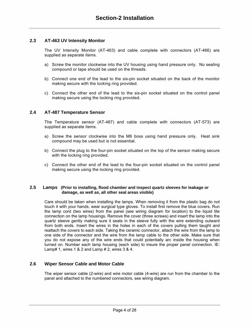
2.3 AT-463 UV Intensity Monitor
The UV Intensity Monitor (AT-463) and cable complete with connectors (AT-466) are supplied as separate items.
a) Screw the monitor clockwise into the UV housing using hand pressure only. No sealing
compound or tape should be used on the threads.
b) Connect one end of the lead to the six-pin socket situated on the back of the monitor making secure with the locking ring provided.
c) Connect the other end of the lead to the six-pin socket situated on the control panel
making secure using the locking ring provided. 2.4 AT-487 Temperature Sensor
The Temperature sensor (AT-487) and cable complete with connectors (AT-573) are supplied as separate items.
a) Screw the sensor clockwise into the M6 boss using hand pressure only. Heat sink
compound may be used but is not essential.
b) Connect the plug to the four-pin socket situated on the top of the sensor making secure with the locking ring provided.
c) Connect the other end of the lead to the four-pin socket situated on the control panel
making secure using the locking ring provided.
2.5 Lamps (Prior to installing, flood chamber and inspect quartz sleeves for leakage or damage, as well as, all other seal areas visible)
Care should be taken when installing the lamps. When removing it from the plastic bag do not touch it with your hands, wear surgical type gloves. To install first remove the blue covers. Run the lamp cord (two wires) from the panel (see wiring diagram for location) to the liquid tite connection on the lamp housings. Remove the cover (three screws) and insert the lamp into the quartz sleeve gently making sure it seats in the sleeve fully with the wire extending outward from both ends. Insert the wires in the holes in each of the covers pulling them taught and reattach the covers to each side. Taking the ceramic connector, attach the wire from the lamp to one side of the connector and the wire from the lamp cable to the other side. Make sure that you do not expose any of the wire ends that could potentially arc inside the housing when turned on. Number each lamp housing (each side) to insure the proper panel connection. IE: Lamp# 1, wires 1 & 2 and Lamp # 2, wires 3 & 4.
2.6 Wiper Sensor Cable and Motor Cable
The wiper sensor cable (2-wire) and wire motor cable (4-wire) are run from the chamber to the panel and attached to the numbered connectors, see wiring diagram.

Section-3 Control & Operation
Page 5 of 28
3 Control & Operation 3.1 Display Layout.
3.2 Basic Operation The SPECTRA control panels are operated via the front membrane. The membrane consists of three main buttons (Start, Stop and Reset), a four button keypad used for controlling a vacuum fluorescent display (VFD) and two LED’s (Running and Fault). Pressing the Start button activates the start-up sequence, which turns on the lamp(s). During start-up, the Running LED flashes on and off. The start-up sequence takes up to three minutes to complete, allowing the lamp enough time to warm up and reach the maximum UV output. For Multi-lamp Systems, the lamps are started in sequence at 7.5s intervals to allow for current surges to settle between lamp strikes. When dose has been achieved, the system enters running mode, indicated by a steady Running LED. The Stop button will turn off the lamp and start the re-strike timer, which prohibits the lamp being struck again for eight minutes to allow it to cool down to allow a re-strike. Pressing Start will have no effect while the re-strike timer is running. The Reset button is used to re-set any faults that have occurred. This is explained in detail in the section on fault screens.
START STOP RESET
RUNNING WARRINGTON, ENGLAND+44 (0)1942 685511t FAULT

Section-3 Control & Operation
Page 6 of 28
3.3 Keypad Operation The more sophisticated functions of the SPECTRA are accessed via the keypad. The keypad has the buttons Up, Down, Enter and Clear. It allows the operator to scroll through all the screens, enter values for set points and select various control options. 3.4 Main Screens (displayed in normal running mode) This section details operator access without using password screens or triggering any control sequence. The main screens are accessed using the Up (↑) and Down (↓) arrow buttons, with sub screens accessed as using the Enter (↵) & Clear (X) buttons.
Software Version On initial power up of the spectra the Version of Software installed is displayed for 10 seconds.
Dose & Flow Rates The default screen displays the instantaneous dose rate & either the water flow measured or assumed through the chamber instantaneous or pre-set flow rate. This screen is displayed automatically if the keypad has not been used for 5 minutes.
UV Intensity The mA & % UV Intensity reading for the first monitor is continuously displayed. Pressing the Enter (↵) button, allows access to the multi-monitor display mode, pressing the Up (↑) or Down (↓) button allows the mA & % UV Intensity of any subsequent monitors to be accessed. Pressing the Clear (X) button exits the multi-monitor display mode. The screen displays both (4-20mA) and (0-100%) for calibration purposes.
Lamp Current The current reading for the first UV lamp is continuously displayed. Pressing the Enter (↵) button, allows access to the multi-lamp display mode, pressing the Up (↑) or Down (↓) button allows the current of any subsequent UV lamps to be accessed. Pressing the Clear (X) button exits the multi-lamp display mode.
Transmission (Not Used) If a transmisivity instrument is fitted then the transmission of the process fluid can be displayed in T1, T2, T4 & T5 cells.
Lamp and System Run Hours The ‘Lamp Run Hours’ displays the number of hours which the lamp has run since it was last changed. Note: Individual Lamp Run Hours are not displayed, this should be borne in mind when individual lamps are changed. The ‘Lamp Run Hours’ can be re-set in the operators section once the lamp has been changed. (Lamp Run Hours are used to determine which of the available systems should be brought on line when multiple SPECTRA systems are used in conjunction with a PLC control system). The ‘System Run Hours’ displays the number of hours the system has been running since installation.

Section-3 Control & Operation
Page 7 of 28
Temperature and PSU Status
The power supply thermostat is displayed as a status (OK) & the chamber temperature is displayed in engineering degrees. When more than one temperature probe is fitted only the highest temperature is displayed. Pressing the Enter (↵) button, allows access to the multi-monitor display mode, pressing the Up (↑) or Down (↓) button allows the temperature of any subsequent monitors to be accessed. Pressing the Clear (X) button exits the multi-monitor display mode.
Spares and Service The service centre telephone number is displayed by pressing the Enter (↵) button. Pressing the Up (↑) or Down (↓) button allows access to the UV Lamp, Quartz & Quartz Seal part numbers. Pressing the Clear (X) button exits the part number display mode.
Time and Date The Time displayed in the following format: hh:mm:ss (e.g. 18:35:42 ). The Date displayed in the following format: DDD dd/mm/yyyy (e.g. TUE 22/04/2002 ).
Section-3 Control & Operation
Page 8 of 28
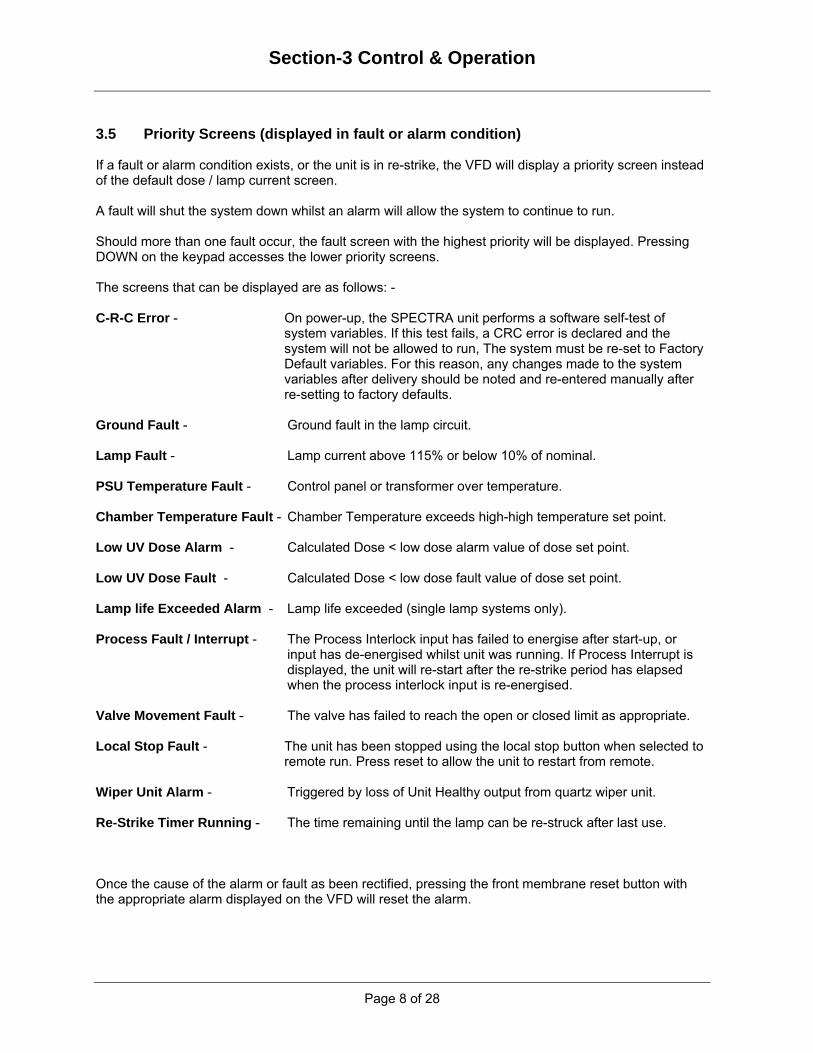
3.5 Priority Screens (displayed in fault or alarm condition) If a fault or alarm condition exists, or the unit is in re-strike, the VFD will display a priority screen instead of the default dose / lamp current screen. A fault will shut the system down whilst an alarm will allow the system to continue to run. Should more than one fault occur, the fault screen with the highest priority will be displayed. Pressing DOWN on the keypad accesses the lower priority screens. The screens that can be displayed are as follows: - C-R-C Error - On power-up, the SPECTRA unit performs a software self-test of
system variables. If this test fails, a CRC error is declared and the system will not be allowed to run, The system must be re-set to Factory Default variables. For this reason, any changes made to the system variables after delivery should be noted and re-entered manually after re-setting to factory defaults.
Ground Fault - Ground fault in the lamp circuit. Lamp Fault - Lamp current above 115% or below 10% of nominal. PSU Temperature Fault - Control panel or transformer over temperature. Chamber Temperature Fault - Chamber Temperature exceeds high-high temperature set point. Low UV Dose Alarm - Calculated Dose < low dose alarm value of dose set point. Low UV Dose Fault - Calculated Dose < low dose fault value of dose set point. Lamp life Exceeded Alarm - Lamp life exceeded (single lamp systems only). Process Fault / Interrupt - The Process Interlock input has failed to energise after start-up, or
input has de-energised whilst unit was running. If Process Interrupt is displayed, the unit will re-start after the re-strike period has elapsed when the process interlock input is re-energised.
Valve Movement Fault - The valve has failed to reach the open or closed limit as appropriate. Local Stop Fault - The unit has been stopped using the local stop button when selected to
remote run. Press reset to allow the unit to restart from remote. Wiper Unit Alarm - Triggered by loss of Unit Healthy output from quartz wiper unit. Re-Strike Timer Running - The time remaining until the lamp can be re-struck after last use. Once the cause of the alarm or fault as been rectified, pressing the front membrane reset button with the appropriate alarm displayed on the VFD will reset the alarm.

Section-3 Control & Operation
Page 9 of 28
3.6 Operator Screens (used to set commissioning parameters) The operator screens are accessed via by pressing ENTER when the dose screen is displayed. The operator enters a three-digit password (default ‘ets’ or ‘atg‘). Check all settings prior to startup. The operator menu area is split into a number of sections accessed through header screens. Press ENTER (↵) to drill deeper into the screen hierarchy and to accept changes to variables. Press the UP (↑) and DOWN (↓) buttons to select the relevant screen within a section and to change system variable values. Press CLEAR (X) to return to higher screens in the hierarchy and to discard changes to system variables.
FLOW Screens Set Flow Rate Set Start Flow Set Low Flow Flow Meter K-Flow
LAMP Screens Nominal Lamp Current Set Lamp Life Reset Lamp Hours Set Re-Strike Time Set Number CT Turns Number of Lamps Lamps in Use K-Intensity
DOSE Screens Dose Set-Point Dose Low Error Band Dose Low Error Time Dose Upper Error Band Dose Upper Error Time Low Power S-P Dose Alarm Level Dose Fault Level Low Power Switching Enable Low Power Timing Low Dose Start Good Dose Time Low Dose Time Low Dose End Time Output Mode Number of UV Sensors K-Time Dose Output enable Dose Output Range
TRANSMISSION Screens Transmission enable Transmission Cell Size
TEMPERATURE Screens Chamber Over-Temperature Bleed System enable Set Bleed On Value Set Bleed Off Value Number of Temperature Sensors
COMMS Screens Communications Address Communications Addressing Long Communications Protocol enable Data Logging enable
VALVES Screens Valve Operation enable Set Valve Operating Time
Miscellaneous Change Password Screens Set Time and Date Local / Remote Auto-Restart Process Interlock enable Set Process Interlock Time Interlock Action Factory Defaults

Section-3 Control & Operation
Page 10 of 28
Default Operator Screen To exit the operator section press Clear (X). To scroll the operator section use the UP (↑)and DOWN (↓) buttons. COMMONLY USED SCREENS ARE DENOTED BY * Check all settings prior to startup. Flow Screens
Set Flow Rate* The operator has to set the flow-rate when the system has no flowmeter fitted. The flow-rate should be set to the maximum system flow.
Set Start Flow* (Set Same as Flow rate) The operator has to set the start flow-rate when the system has a flowmeter fitted. The flow-rate can be set lower than the maximum system flow, this allows the lamp to achieve the maximum output before the system is switched from start-up mode into the run mode. Once in the run mode the flowmeter input is used to calculate the dose.
Set Low Flow (Not Normally Set)) The operator may have to set the low flow-rate when the system has a flowmeter fitted. Flowmeters with a large range are generally inaccurate at low flow-rates. When the flow-rate is low the flowmeter accuracy can cause the output signal to fall to 4mA. If the flow-rate is low (4mA) & the UV intensity high the resulting dose calculation could be infinity, this could result in process fluid passing through the system incorrectly treated. We therefore set the low flow-rate to 1m3/hr, this ensures that the dose is calculated with a minimum flow going through the system
Flow Meter Enable (Normally Disabled) The operator can specify if a flow meter is connected to the SPECTRA unit. If a flow meter is not connected, the flow rate set point is used in the calculation of dose.
Flow Constant k flow (Not Normally Set) k flow is a constant used to convert raw data input from a flow meter into engineering units of flow rate. It is only used when the flow meter input is enabled. Lamp Screens
Nominal Lamp Current* The operator can set the nominal current for the lamp. Actual Current must match Nominal Setting Whilst the system is in running mode, the lamp current is continually checked to ensure it is within 10% to 115% of nominal. If the current is outside these parameters a lamp fault is activated and the lamp shut down. During the 5 minute start up period the lamp current must reach the lower current limit (the lamp must strike) within 10 seconds, and the current must not rise above 250% of the nominal current. If either of these two cases occurs a lamp fault is activated and the lamp shut down.

Section-3 Control & Operation
Page 11 of 28
Set Lamp Life* The operator can set the expected life of the UV lamp. Normally set at 10,000 hours unless discussed with factory technician. If the lamp life is exceeded, a warning is displayed. The warning does not affect the operation of the system, however it is likely that dose will be difficult to maintain once the lamp life is exceeded. Reset Lamp Hours* The operator should re-set the lamp hours when the lamp has been changed. The lamp run hours are shown on the user screens for logging purposes. (In a multi-SPECTRA system with PLC control, the lamp run hours are used to determine which of the available systems is the stand-by). Lamp Re-Strike Time* The operator can set the time required for the lamp to cool down sufficiently to be re-struck after being stopped. Normally set at 8 minutes unless discussed with factory technician. Number of CT Turns (Not Normally Set) The operator can set the number of passes of the lamp supply cable through the current transformer. The lamp current is continually monitored. If a low current lamp is used, the number of passes through the monitoring CT is increased to give better resolution. The number of passes through the CT is used in the calculation of the lamp current.
Number of Lamps (Always Check Both Lamps are Operating (Y) The operator can set the number of lamps fitted in the system. (Note this variable should not be changed in order to remove lamps from service as the dose calculation may be affected. The lamps in service screen below should be used for this purpose.)
Lamps in Use (Systems with more than 2 lamps)) The operator can set which lamps in the system are in service, If a lamp cannot be run, it can be removed from service.
Intensity Constant* k intensity The operator can set the value of k intensity. k intensity is a constant used to convert raw data input from the intensity monitor into mW/cm2 for display, and calculation of the dose. k intensity values for typical systems are tabulated in the appendix.

Section-3 Control & Operation
Page 12 of 28
Dose Screens
Dose Set-Point* The operator can adjust the wall/average dose set-point. This is used in fixed and variable systems to monitor the dose alarm level & dose fault level. In variable systems the dose set-point is also used to control the lamp current to maintain a set dose. This always set to 60mj/cm2 unless discussed with factory technician.
Dose Error Band & Dose Error Time (Not Normally Used) The bandwidth can be adjusted in 1mJ/cm2 steps to a maximum of 10 mJ/cm2 & the time can be adjusted in 1min steps to a maximum of 60min’s. For variable systems when the dose is lower or higher than the bandwidth setting, for the error time setting, then the power to the lamp is increased or decreased to maintain the dose set point.
Low Power Set Point* The operator can adjust the wall/average dose set point to be used when the system is switched into low power with the low power mode set in a ‘Low Dose’ mode. (This setting is expressed as a percentage of full power dose set point as the setting is used alternatively to set the low flow set point if the low power mode set is to ‘Low Flow’ mode). This is normally set at 50 % unless discussed with factory technician.
Dose Alarm Level* The operator can set the Dose Alarm level, expressed as a percentage of the dose set point (or low dose set point if in use). Normally set at 100 % The alarm is activated if the dose drops below this setting, it is displayed on the VFD but the system is allowed to continue running.
Dose Fault Level* The operator can set the Dose Fault level, expressed as a percentage of the dose set-point (or low dose set point if in use). Normally set at 10%. The fault is activated if the dose drops below this setting, it displayed on the VFD and the system is shut down. Low Power Switching* There are two methods of controlling the low power switching, an internal timer & an external contact (IP-7). If low power switching is enabled (either by internal timer, external contact or both), the Low Power Set Point is used to establish the correct drop in dose or flow. Low power switching is achieved by output (OP-4) being de-activated. This switches out a power section and lowers the current to the lamp. The low power mode is set by one of the following options:
DISABLED The power-switching timer & the external contact are both disabled. Power switching will not operate.

Section-3 Control & Operation
Page 13 of 28
LP.EX.TIM.LD Low Power External & Timed Low Dose mode. Both the external contact & the internal power-switching timer are enabled. The power output is reduced when the external contact is closed or the timer
dictates low power. The dose alarm & fault levels are automatically adjusted to the Low Power Set Points when the power is reduced.
TIM. LD Timed Low Dose mode. This mode must be set to reduce lamp power to 50% at night when using time switching.
The power-switching timer is enabled & the external contact is disabled. The power output is determined automatically by the values specified in the Low
Power Timing menu. The dose alarm & fault levels are automatically adjusted to the Low Power Set
Point when the power is reduced. EX. LD Low power external Low dose mode. The external contact is enabled & the power-switching timer is disabled. When the external contact is closed the power is switched to the low level. The dose alarm & fault levels are automatically adjusted to the Low Power Set
Point when the power is reduced. LOW FLOW Low flow mode. (For duty-standby systems without flowmeter; both running normally at half
power). The external contact is enabled & the power-switching timer is disabled.
The system assumes that the when the external contact is closed, the pre-set flow rate is reduced to the value of the Low Power Set Point.
Low Power Timing* Note: - Both the Low Power Timing settings & the relevant Low Power Switching option must be enabled to utilise the low power switching function, setting the timer is not sufficient to ensure correct operation. The first screen allows selection of individual, whole week, weekdays or weekend for changing times. The second screen allows switching times to be entered. Up to four switching times can be used per day. If not all times are required, spare slots should be set at 99:99. Times allowed for switching are limited to 15-minute intervals from 00:15 to 23:45. A time used for switching to full power is followed by a ‘ + ‘ sign, Times used for switching to half power are followed by a ‘–‘ sign. To run at half power for a full day, the first two times should be set at 00:15 + and 00:15 – . To run at full power all day the first two times should be set 00:15 – and 00:15 +. Times must be ascending eg 00:30- 07:30+ NOT 07:30+ 00:30- Low Dose Start (Not Normally Used) It is possible for the operator set the required action if the dose set point is not achieved within three minutes of the system starting. If enabled, the system will be allowed to continue to run. (Low dose fault may still shut the system down if the dose is below the fault threshold). If disabled, the system will shut down and declare a low dose fault (even if the dose was above the low dose fault threshold). Good Dose Time (Not Normally Used) During start-up, the dose is calculated using the chamber maximum flow (start-up flow). The system must achieve set-point dose for the good dose time for the system to switch to running mode.

Section-3 Control & Operation
Page 14 of 28
Low Dose Time (Not Normally Used) Whilst the system is running, the dose is continually monitored. If the systems dose drops below the alarm or fault values, the low dose timer is started (on variable systems the output is also increased to maximum). If the dose does not recover and the low dose timer expires, a low dose alarm / fault is activated and the system shutdown if required.
Low Dose End Time Not Normally Used) Whilst the low dose timer is running, if the dose recovers for the low dose end time, the system is returned to normal running. If this time is not achieved before the low dose timer expires, i.e. dose is not re-established for the low dose end time, a low dose alarm / fault is activated and the system shutdown if required.
Output Mode (Not Normally Used) The output mode can be set as follows:
None No output is configured. Stage Digital Switching Analogue Power External 4-20mA Lamp Current Control (0-100%). Analogue Intensity External 4-20mA UV Intensity Indication (0-100%).
Number of UV Sensors (Maxi-Mux Only)
The operator can set the number of UV probes fitted to the system. The intensity readings from the UV probes are used to calculate the system dose. When multiple UV probes are fitted, access to individual intensity readings can be accessed by pressing the Up (↑) or Down (↓) buttons to the INTENSITY screen & pressing the Enter (↵) button. This displays UV Input 1, pressing the Up (↑) or Down (↓) buttons displays the other inputs.
Set Time Constant k time (Verify Setting from Appendix) The operator can set the value of k time. k time is a constant used in the calculation of dose and is based on the dimensions of the chamber to give the time taken for water to pass the lamp arc at unit flow. k time values for typical systems are tabulated in the appendix. Dose Output & Dose Output Range ( Not Normally Used) The Dose Output can be set as follows:
Disabled = No output is configured. Enabled = External 4-20mA Dose Indication. Dose Output Range = Span between 0 - 250mJ/cm2

Section-3 Control & Operation
Page 15 of 28
Transmission Screens ( Not Used)
Process Fluid Transmission (Optional feature) The operator can enable the input mode can be set as follows:
Disabled = No output is configured. Enabled = External 4-20mA Transmission Input. Transmission Range = T1, T2, T4 & T5 Cells
Temperature Screens
Chamber Over-Temperature Fault* (Set at 114 degrees F)
The operator can specify the maximum chamber temperature allowed before the SPECTRA unit is to shut down. The chamber temperature is constantly monitored in software. If the temperature exceeds the maximum safe working temperature an over-temperature fault is activated and the lamp shut down. Note: The temperature is also monitored in hardware and limited to a maximum value. (Adjustable up to 140°F using VR1 on the SPECTRA control board.) If the hardware temperature trip value is exceeded, the lamp will be shut down directly, resulting in a lamp fault being activated.
Bleed System Enable (Not Normally Used) Generally used in closed loop systems to open a solenoid valve at a given temperature & close at a higher temperature, allowing process fluid to bleed from the chamber keeping the lamp cool. (This temperature limit is also used in a PLC controlled system to provide a flag for high chamber temperature before the chamber high temperature fault is activated. This allows changeover to a stand-by unit if available).
Bleed ON Value (Not Normally Used) The temperature set point at which the bleed valve opens.
Bleed OFF Value (Not Normally Used)
The temperature set point at which the bleed valve closes.
Number of Temperature Sensors (Maxi-Mux Only)
The operator can set the number of temperature sensors fitted to the system. The highest temperature reading from the temperature sensors is displayed. When multiple temperature sensors are fitted, access to individual probe readings can be accessed by pressing the Up (↑) or Down (↓) buttons to the TEMPERATURE screen & pressing the Enter (↵) button. This displays Temperature Input 1, pressing the Up (↑) or Down (↓) buttons displays the other inputs.

Section-3 Control & Operation
Page 16 of 28
Comms. Screens (Not Normally Used)
Communications Address For multiple SPECTRA systems controlled by a PLC, the unit requires an individual address (A – Z) for the PLC to communicate using an RS422 network. The operator can change the communication address using this screen.
Enable Communications Addressing The operator can specify if the system is to use addressing for serial communications. If communications addressing is disabled, the system defaults to address ‘A’ for serial communications.
Enable Long Communications Protocol The operator can specify if the system is to use the long communications protocol for serial communications. Communications with the spectra uses an ASCII protocol to retrieve / set variables stored in EEPROM / Battery backed ROM and to download data stored during logging. Normally variables are read / written individually by address. However, if long communications protocol is enabled, reading the flow rate data address results in a number of other addresses being read as well as the flow rate data. This allows faster processing of key data in PLC controlled multiple SPECTRA systems.
Enable Data Logging The operator can enable the SPECTRA to log system status to internal memory for later retrieval using RS232 communications. A number of key variables are stored in non-volatile memory at regular intervals and when the system status or alarm states change. When the memory is full, the oldest data is over-written. By default, the memory can store information for approx. one week. This information can be retrieved using a laptop PC via the RS232 communications port. Valve Screens (Not Normally Used)
Enable Valves The operator can specify if valve position feedback is used in the system. If the system uses valve position feedback, the valve position is continuously checked and the Valve Operating timer is started if the valve is out of position. If the timer expires, a valve movement fault is activated and the system shut down. If the valve position feedback is used, after establishing dose on starting, the valve must attain the open position before the system is allowed to enter the run mode. On stopping, the valve is closed before the lamp is extinguished (the running LED is extinguished whilst the valve is closing).
Valve Operating Time The operator can set the time allowed for the actuation of a valve. The timer is started whenever one of the following is true: - • The valve is set to open –AND– (The valve-opened input is not set –OR– The valve-closed input is
not re-set)

Section-3 Control & Operation
Page 17 of 28
• The valve is set to close –AND– (The valve-closed input is not set –OR– The valve-opened input is not re-set).
If the timer expires, a valve movement fault is activated (if enabled). Miscellaneous Screens
Change Operator Password* The operator has the option of changing the operator password.
Change Time and Date* (Sequence is Day/Month/Year) The operator can set the correct time, date and day. Access to this facility is not allowed if the re-strike timer is running.
Local / Remote Control* The operator can set the system to be used in local or remote mode. In local mode, the system can be run from the start and stop buttons on the front panel membrane. In Remote mode, the system is controlled using the remote run input or via serial communications. The front membrane stop button can always be used to stop the SPECTRA unit. Note: In Remote mode, the equipment can start unexpectedly even if stopped using the front membrane stop button or the stand-by request button on the HMI (if used).
Enable Auto Re-Start* (Should be left in Auto Mode)
The operator can specify if the system is to automatically re-start if it was running when a power failure occurred. Note: Ensure that there are no risks to personnel or machinery on unexpected automatic re-start. If a power failure occurs, normally the lamp will extinguish and on restoration of power the start button is required to be pressed before the system will re-start. If Auto Re-Start is enabled; if the system is running when the power fails, when the supply is restored and the re-strike timer is expired the lamp will be re-started automatically.
Process Interlock Settings* The operator can specify if the SPECTRA is to react to a loss of a process variable (eg. flow). A process interlock input is provided for this purpose. If the process interlock is enabled, the Process Interlock Time screen is displayed. The operator can input the time for which the Process Interlock Input is ignored after start-up for the process variable to be established. If the process interlock is enabled, the Process Interlock Action screen is displayed. The operator can set the system response to a loss of the Process Interlock Input once the SPECTRA unit is running. If set to shutdown, the system will be stopped and a Process Fault activated. If set to interrupt, the system will be stopped until the process variable is re-established and the re-strike timer has expired, when system will be re-started.
Re-set Factory Defaults* It is possible for the operator to reset the system variables back to the factory settings. It is important that any changes made to the system settings after delivery should be noted so that they can by re-set manually after applying factory default settings.
Section-3 Control & Operation
Page 18 of 28
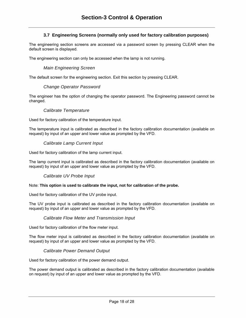
3.7 Engineering Screens (normally only used for factory calibration purposes) The engineering section screens are accessed via a password screen by pressing CLEAR when the default screen is displayed. The engineering section can only be accessed when the lamp is not running.
Main Engineering Screen The default screen for the engineering section. Exit this section by pressing CLEAR.
Change Operator Password The engineer has the option of changing the operator password. The Engineering password cannot be changed.
Calibrate Temperature Used for factory calibration of the temperature input. The temperature input is calibrated as described in the factory calibration documentation (available on request) by input of an upper and lower value as prompted by the VFD.
Calibrate Lamp Current Input Used for factory calibration of the lamp current input. The lamp current input is calibrated as described in the factory calibration documentation (available on request) by input of an upper and lower value as prompted by the VFD.
Calibrate UV Probe Input Note: This option is used to calibrate the input, not for calibration of the probe. Used for factory calibration of the UV probe input. The UV probe input is calibrated as described in the factory calibration documentation (available on request) by input of an upper and lower value as prompted by the VFD.
Calibrate Flow Meter and Transmission Input Used for factory calibration of the flow meter input. The flow meter input is calibrated as described in the factory calibration documentation (available on request) by input of an upper and lower value as prompted by the VFD.
Calibrate Power Demand Output Used for factory calibration of the power demand output. The power demand output is calibrated as described in the factory calibration documentation (available on request) by input of an upper and lower value as prompted by the VFD.

Section-4 Calibration
Page 19 of 28
4 Calibration
4.1 Calibration of the AT-463 UV Intensity Monitor The UV lamps emit short wave radiation which can be damaging to eyes and skin. At no time should personnel be exposed to this radiation.
a) The UV intensity monitor input needs to be adjusted to 100% on system commissioning
with the chamber full of the process fluid and a new lamp and clean quartz fitted. Once the UV Intensity monitor has been installed on the chamber remove the 4 screws and open the lid.
b) Inside, two potentiometers and a four-pole dipswitch are visible; the zero potentiometer is
factory set and sealed.
c) Press the start pushbutton and allow the lamp to stabilise for approximately ten minutes. With the Spectra default screen showing Dose and Flow press the DOWN (↓) button to select Intensity, then the Enter button to display Intensity %.
d) The dipswitches set the amplification range with position 1 being the highest gain and
position 4 being the lowest gain. (It is likely that the unit will have been shipped from the factory with the correct dipswitch already selected).
Location of the DIPSWITCHES and the SPAN POTENTIOMETER Upon the AT-463 UV Intensity Monitor Circuit Board
DIPSWITCHES
SPAN POTENTIOMETER

Section-4 Calibration
Page 20 of 28
e) Adjust the UV probe head Span potentiometer until the Intensity reading is 100%. If it is not
possible to achieve 100% then change to the next higher or lower gain dipswitch.
f) Press the stop pushbutton. The intensity reading should read 0%. Wait a few minutes for the lamp to cool and restart the unit. After restart the intensity display should settle back to approx 100%.
g) The UV Intensity monitor is now set up correctly, no further adjustments need be made.
h) Close the UV Intensity monitor’s lid and replace the 4 screws.

Section-5 Replacements
Page 21 of 28
5 Replacements 5.1 Replacing the UV Lamp
a) Isolate the control panel via the door inter-locked isolator. b) Close the process isolation valves.
c) Remove the wiper mechanism cover.
d) Remove the lamp covers from both sides of the chamber. e) Disconnect the UV lamp from the ceramic terminals.
f) Remove the lamp supports. g) Remove the new lamp from its wrapping and lay it gently on top. h) Keeping the old lamp parallel to the quartz sleeve carefully withdraw it from the
chamber. i) Place the old lamp on top of the wrapping and exchange the old lamp with the new one. j) Gently ease the new lamp back into the quartz sleeve. k) Push the lamp cable through the hole in the lamp supports and fix them back in position
with the fixing screws. l) Reconnect the UV lamp to the ceramic terminals. m) Replace the lamp covers to both sides of the chamber.
n) Refit the wiper mechanism cover. o) Open the process isolation valves.
p) Switch the control panel on via the door inter-locked isolator.
q) Reset the lamp hours counter (refer to section 3).

Section-5 Replacements
Page 22 of 28
5.2 Replacing the Quartz Sleeve
a) Isolate the control panel via the door inter-locked isolator.
b) Close the process isolation valves. c) Remove the wiper mechanism cover. d) Remove the lamp covers from both sides of the chamber.
e) Disconnect the UV lamp from the ceramic terminals. f) Remove the lamp supports. g) Keeping the lamp parallel to the quartz sleeve carefully withdraw it from the chamber.
h) Place the lamp on top of a safe and clean surface.
i) Remove the ‘Vent’ & ‘Drain’ hex caps wait until the UV chamber is empty.
j) Remove the ‘Clamp Ring’ & ‘O’ seal from the end of the chamber.
k) Remove the new quartz sleeve from its wrapping and lay it gently on top.
l) Keeping the old quartz sleeve parallel to the floor carefully withdraw it from the chamber.
m) Place the old quartz sleeve on top of the wrapping and exchange the old quartz sleeve with
the new one.
n) Keeping the new quartz sleeve parallel to the floor gently ease it back into the chamber.
o) Refit the ‘Clamp Ring’ and a new ‘O’ seal to the end of the chamber.
Refit a new ‘O’ seal and gradually tighten in rotation the ‘Clamp Ring’ screws. DO NOT OVERTIGHTEN. The design of the ‘Clamp Ring’ gives a pre-set compression of the 'O' seal. When the quartz is viewed from the inside, the ‘O’ seal will appear as a continuous black ring 1.5mm to 2.0mm (approx 1/16 inch) wide and this is adequate for normal water pressures. Check the quartz for possible cracking by carefully running a finger nail across the ‘O’ seal end of quartz area.
p) Refit the ‘Vent’ & ‘Drain’ hex caps.
q) Gently open the process isolation valve and wait for the chamber to fill.
r) Check the Clamp Ring and ‘O’ seal for leaks.
s) Gently ease the lamp back into the quartz sleeve.
t) Push the lamp cable through the hole in the lamp supports and fix them back in position
with the fixing screws.
r) Replace the lamp covers to both sides of the chamber.
s) Refit the wiper mechanism cover
t) Switch the control panel on via the door inter-locked isolator.

Section-5 Replacements
Page 23 of 28
5.3 Replacing the Quartz Window
a) Stop the unit and isolate the control panel via the door inter-locked isolator.
b) Close the process isolation valves.
c) Remove the ‘Vent’ & ‘Drain’ hex caps and wait until the UV chamber is empty.
d) Unscrew the locking ring on the rear of the monitor & disconnect the six-pin connector.
e) Remove the UV monitor from the UV housing by unscrewing anti-clockwise.
f) Using an Allen Key, remove the socket head screws split the loose section of the probe
housing from the fixed section.
g) Remove the ‘Quartz Window’ & ‘O’ seals.
h) Clean the internal and external surfaces of the window and the internal surfaces of the two sections of the UV housing before refitting takes place.
i) Place one ‘O’ seal on the seat of the fixed section of the UV housing.
j) Place the other ‘O’ seal on the seat of the loose section of the UV housing and rest the
quartz window on top of the ‘O’ seal.
k) Offer the loose section of the UV housing up to the fixed section, taking care not to drop the quartz window.
The design of the ‘UV housing’ gives a pre-set compression of the 'O' seal and this is adequate for normal water pressure. Refit a new ‘O’ seal and gradually tighten in rotation the ‘Clamp Ring’ screws. DO NOT OVERTIGHTEN.
l) Refit the ‘Vent’ & ‘Drain’ hex caps.
m) Gently open the process isolation valve and wait for the chamber to fill.
n) Screw the monitor clockwise into the UV housing using hand pressure only. No sealing compound or tape should be used on the threads.
o) Connect one end of the lead to the six-pin socket situated on the back of the monitor
making secure with the locking ring provided

Section-6 Maintenance Schedule
Page 24 of 28
6 Maintenance Schedule 6.1 Maintenance Log
Whenever maintenance work is carried out on the UV system, particularly with reference to lamp changes and cleaning/replacing the quartz, a record should be kept of the work carried out and the lamp run hours noted. This log should be used to monitor general lamp life and to develop accurate frequencies for cleaning and replacing the quartz components. A maintenance log sheet is contained in the appendix.
6.2 Performance Monitoring
Taking samples from the sample points on the inlet and outlet legs of the UV chamber can monitor the performance of the system. Care should be taken when sampling not to contaminate the sample itself. Poor performance test results can often be traced back to poor sampling techniques.
6.3 UV Lamp
Lamp life expectancy is 4000 hours continuous use before the output drops to the low UV output threshold level, making replacement necessary. Frequent stop/start operation will reduce lamp life.
6.4 Quartz Cleaning and Replacement
The quartz thimble should be removed and cleaned at a regular interval. Initially this should be after approximately 4000 hours. The cleaning frequency should be increased if there are excessive deposits on the quartz thimble or decreased if the thimble remains very clean. A change in water quality may necessitate a change in the cleaning frequencies. We recommend that the quartz thimble be replaced after 16,000 hours regardless. The quartz thimble should be removed and cleaned in a soap and water solution. Heavier or stubborn deposits can be removed by soaking in a 5% solution of citric acid or wiping with household vinegar. To remove fingerprints from the quartz thimble, use surgical spirit and a lint free cloth.
6.5 Seals
It is good practice to replace the seals whenever the quartz thimble is removed from the chamber.
6.6 Control panel Commissioning often takes place in a dusty environment. The inlet filter mat should be cleaned shortly after commissioning and every 6 months thereafter if the cooling air is clean. The control panel RCD (ground fault relay) should be tested every 6 months by an electrically competent person by pressing it’s Test button. Note that this will shut the unit down and display Ground Fault.

Section-6 Maintenance Schedule
Page 25 of 28

Section-7 Fault Finding
Page 26 of 28
7 Fault Finding 7.1 UV Disinfection System Trips on Lamp Fault
a) Ensure miniature circuit breaker has not tripped.
b) Check the lamp life has not expired.
c) Check the connections to the lamp are correct. 7.2 UV Disinfection System Trips on Low UV
a) Check the lamp life has not expired
b) Clean the quartz thimble.
c) Clean the Quartz viewing window

Appendix
Page 27 of 28
Recommended Spares UV Intensity Monitoring Spares
Qty Description Part No. 1 4-20mA UV Intensity Monitor (AT-463) W6163000 1 UV Intensity Monitor Lead (AT-466) W6164000 2 Quartz Window – Top Hat Style (40dia x 6) W2900260 4 Quartz Window ‘O’ Seal W3400160
Temperature Monitoring Spares
Qty Description Part No. 1 Temperature Sensor (AT-487) W6168006 1 Pt-100 Temperature Sensor Lead (AT-573) W6168007
Common Chamber Spares
Qty Description Part No. 2 Front & Rear ‘O’ Seal (160.0 x 4.0) W3300275 4 Cover Plate ‘O’ Seal (69.5 x 3) W3400175 2 Quartz ‘O’ Seal (SS-36) W3200300
ECF-215 Chamber Spares
Qty Description Part No. 2 Quartz Sleeve (QSL-36 x 318-320) W2020115 2 UV Lamp (MP15D) W1501220
ECF-220 Chamber Spares
Qty Description Part No. 2 Quartz Sleeve (QSL-36 x 368-370) W2020200 2 UV Lamp (MP20D) W1501300
ECF-225 Chamber Spares
Qty Description Part No. 2 Quartz Sleeve (QSL-36 x 418-420) W2020290 2 UV Lamp (MP25D) W1501400
ECF-230 Chamber Spares
Qty Description Part No. 2 Quartz Sleeve (QSL-36 x 468-470) W2020355 2 UV Lamp (MP30D) W1501415

Appendix
Page 28 of 28
Typical system K values
Unit designation
K intensity
K time
ECF-215-6 17.67 37.21 ECF-220-6 16.33 79.69 ECF-220-8 15.74 66.36 ECF-225-8 16.11 120.33 ECF-225-10 15.49 92.62 ECF-230-10 14.14 197.83 ECF-230-12 13.43 141.55

Appendix
Page 29 of 28
MAINTENANCE LOG
Copy system key maintenance data from the sticker on the inside of the control cabinet door Model: Serial No: Input: Max operating pressure: Max flow rate: UV lamp: Quartz: Commissioning Date: Regular Maintenance Durations: - UV Lamp replacement– As required, typically 8000 to 10,000 hours Cooling Fan Filter – Cleaned every 6 Months Control panel RCD (ground fault relay) – Test every 6 months Quartz Sleeve/Thimble replacement– Every 18 Months
Date Activity Hours Run Comments

Appendix
Page 30 of 28

ECF Rotary Quartz Wiper System
Installation, Operation and Maintenance Manual
This document contains confidential and proprietary information of atg Willand Ltd. In consideration of the receipt of this document, the recipient agrees not to reproduce, copy, use or transmit this document and/or information contained therein in whole or in part, or to permit such action by others, for any purpose, without written permission first being obtained from atg Willand Ltd.

ECF Rotary Quartz Wiper System
Installation, Operation and Maintenance Manual
Revision Reason Date
1 Original Issue 07.06.04 2 Wiper Ring maintenance amended 10.08.04 3 Split Wiper Mounting Plate Description Added 26.04.05

ECF Rotary Quartz Wiper System
Installation, Operation and Maintenance Manual
Connection Diagram Please note: - The Motor, Optical Detector & Alarm Output are polarity conscious; care should be taken to ensure they are connected correctly. When reading these instructions, you should be stood with the motor side of the chamber just in front of you. The near side of the chamber is the motor side & the far side of the chamber is the UV monitor side.

ECF Rotary Quartz Wiper System
Installation, Operation and Maintenance Manual
There are three LED's and a seven-segment display fitted to the control board to indicate the status of the system. LED1 Optical detector slot blocked Red LED When this LED is on the sensor cam has blocked the optical detector. LED2 Optical detector connection ok Green LED This LED is connected in series with the LED mounted within the optical detector and therefore indicates that the circuit is healthy. LED3 Mains on Red LED Indicates a 240vAC supply has been applied to the control board. SSD1 Diagnostics Display Red Seven Segment LED Display The display shows the calibration progress as given in the calibration section below. It also shows the direction of travel of the carriage and the side of the chamber at which the carriage is stopped during normal operation.
– Power-up Reset, reading system data (5 second timer) or System disabled (SW1 off).
– System Not Calibrated.
to – System in Set-up mode (See Calibration Section Below).
– Run time in excess of 8 minutes. (Toggle SW1 and then re-calibrate).
– Loss of input pulses. (Toggle SW1 and then re-calibrate).
– Over-current detected. (Toggle SW1 and then re-calibrate).
– Stopped in the correct position at the far side of the chamber. (Note: - this symbol may be alternating with the number (1-9) times that the system as recovered from a crash).
– The dot on the display will be flashing:- 1:1 mark space ratio to denote automatic timing in operation. 4:1 mark space ratio to denote waiting for manual run input.
– Stopped in the correct position at the near side of the chamber. (Note: - this symbol may be alternating with the number (1-9) times that the system as recovered from a crash).
– The dot on the display will be flashing:- 1:1 mark space ratio to denote automatic timing in operation. 4:1 mark space ratio to denote waiting for manual run input.

ECF Rotary Quartz Wiper System
Installation, Operation and Maintenance Manual
> > > > > – Carriage running towards the far side of chamber. (Segments rotating clockwise, dot illuminated.)
> > > > > – Carriage running towards the near side of chamber. (Segments rotating anti-clockwise, dot illuminated.)
A Potentiometer is used to set-up the electronic current trip. VR1 – Adjusts the level of current the wiper motor can draw before the current trip circuit
detects an overload and locks the system out. Selector Switches and a Push Button allow the wiper to be set-up easily. SW1 – System Enable toggle switch (On-Off).
If this switch is not made, the system is disabled and will not run or will stop running.
SW2 – Set-up Direction toggle switch.
With the system in ‘Set-up’ (DIP switch 4 = ON.): - (See Calibration Procedure below)
If SW2 is set to the IN or OUT position, when PB1 is pressed the wiper carriage is driven along the quartz and will stop at over-current trip. If SW2 is set to the centre RUN position, when PB1 is pressed the wiper carriage will run to the centre of the chamber to ease the removal / re-fitting of the quartz. Pressing PB1 a second time will stop the wiper carriage.
With the system in run mode (DIP switch 4 =OFF.): - If SW2 is set to the IN or OUT position, when PB1 is pressed, if the wiper is in the opposite position carriage is driven along the quartz and will stop at the correct position at the far side of the chamber. The dwell timer is reset in automatic operation. If SW2 is set to the centre RUN position, when PB1 is pressed has no effect except after leaving Set-up mode, the wiper carriage will run to the far side of the chamber ready for automatic or manual operation.
PB1 – Set-up (run) pushbutton.
Used in conjunction with SW2 as described above.

ECF Rotary Quartz Wiper System
Installation, Operation and Maintenance Manual
DIPSW1 – Time Select / Manual and Set-up Enable. A 4-way (DIP) switch module is fitted to the control board.
Switches 1, 2 & 3 are used for setting the time delay between wiping cycles and switch 4 allows the system to be calibrated.
DIP1 0 1 0 1 DIP2 0 = Manual 0 = 1 Min 1 = 15 Min's 1 = 30 Min's DIP3 0 0 0 0 DIP1 0 1 0 1 DIP2 0 = 1 Hour 0 = 6 Hour's 1 = 12 Hour's 1 = 24 Hour's DIP3 1 1 1 1 DIP4 0 = System Run DIP4 1 = System Set-up
Note: - The system should not be left in the 1-Min position as this will exceed the motor duty cycle, causing the temperature of the motor to rise and also reducing the life of the seals and wiper blades. Cables Types
The optical detector operates at 5vDC and the motor operates at 24vDC, therefore we recommend that the following cables should be used for the wiper system. Optical Detector
3 core screened cable (DEF 61-12 Part5). CSA 0.5mm sq.
Motor 2 core YY cable.
CSA 1.0mm sq.
ON
1 2 3 4
ON = 1 OFF = 0

ECF Rotary Quartz Wiper System
Installation, Operation and Maintenance Manual
Software Description
On power-up, the system checks non-volatile memory to see if the system is calibrated. If the system is calibrated, and is not in Set-up mode, the carriage is driven to the far side of the chamber. If the system is not in manual mode, the dwell timer is started. If the system is not calibrated, the software will wait for the set-up procedure to be run. If the system is in Set-up mode, the software will wait for user input. In automatic mode, the timer (DIP) switch settings are continually monitored. If the dwell timer exceeds the required time setting, the motor is run to drive the wiper carriage to the far side of the chamber. The wiper then waits for 2 second’s & drives back to the near side of the chamber. The wiper can be driven to the opposite side of the chamber and the timer reset by use of a fleeting closed contact at the manual run input. In manual mode, the software will wait for a fleeting closed contact at the manual run input and then the motor is run to drive the wiper carriage to the far side of the chamber & back to the near side of the chamber. When the motor is running, the software counts the pulses from the optical detector to monitor the position of the wiper. The motor is stopped when the wiper carriage is six pulses short of the side of the chamber. In Automatic mode, the dwell timer is re-started to repeat the cycle. When the motor is running, the run output (J3^3 & J3^4) is energised. When the system is calibrated, the system healthy output (J3^5 & J3^6) is energised. Whilst the motor is running the optical detector should receive regular pulses, however if the pulse input is lost, the system de-energises the motor and the loss of pulse alarm is generated with the diagnostics display showing fault 9. Notes: -
• On leaving the Set-up mode at any time the first sweep of the chamber must be initiated by pressing PB1.
• If the PB1 is pressed whilst in Set-up and SW2 in the RUN position the carriage will move to the centre of the chamber, this may obstruct the UV Intensity monitor.

ECF Rotary Quartz Wiper System
Installation, Operation and Maintenance Manual
Calibration Procedure
The wiper carriage has to have a geographical reference point in order to know how many pulses to count. Therefore, a procedure for calibration is used.
• Set (DIP SW1) switch 4 to ON (system in Set-up mode). (Diagnostic display = )
• Push SW2 to OUT position.
• Press PB1 (carriage will move to ‘far’ side of chamber)
• Wait for motor to trip on over-current (Diagnostic display = )
• Slide SW2 to IN position.
• Press PB1 (carriage will move to ‘near’ side of chamber)
• Wait for motor to trip on over-current (Diagnostic display = )
• Set DIPSW1 switch 4 to OFF. (Diagnostic display = )
• Slide SW2 to RUN position.
• Press PB1 (the wiper carriage will move to near the ‘far’ side of chamber).
• Wait for motor to stop.
• Ensure Diagnostic display = with the ‘dot’ flashing.
• The wiper carriage waits for 2 sec’s & will return to the ‘near’ side of the chamber).
• Wait for motor to stop.
• Ensure Diagnostic display = with the ‘dot’ flashing.
• Set DIPSW1 switches 1,2 & 3 to required time interval.
Once calibrated, the system stores the number of pulses required to move the carriage from one side of the chamber to the other.

ECF Rotary Quartz Wiper System
Installation, Operation and Maintenance Manual
Commissioning Advice Two ACME shafts drive the wiper carriage, which has to remain parallel at all times. If either of the ACME shafts are rotated more than half a turn in the opposite direction to each other the wiper carriage will jam. Should the ACME shafts be rotated out of sequence and the wiper carriage position is lost, the ACME shafts should be rotated together until the wiper carriage is in the home position prior to the commissioning procedure being carried out. If the wiper system has a good pulse count stored in its memory and the commissioning procedure is being carried out, occasionally the commissioning procedure jumps straight from 3 to 5. Should this happen, the system must have a forced fault condition. To do this, disconnect the pulse counter (via the connector block) and attempt to commission the wiper system. The motor will drive the wiper shaft, but no pulses will be detected and a loss of count fault condition generated. Reconnect the pulse counter and follow the commissioning procedure.
SPARES SCHEDULE
Quantity Description Part No 1 Primary Seal (8mm Dia) W3500005 1 Secondary Seal (8mm Dia) W3500005 1 Sealed Self Lubricating Bearing W5410065 1 50mL Bottle Bearing Seal W5410100
TIMING BELT SPARES SCHEDULE
Quantity Description Part No
1 2 Lamp Timing Belt 330 x L037 1 3 Lamp Timing Belt 380 x L037 1 4 Lamp Timing Belt 430 x L037
WIPER RING SPARES SCHEDULE
Quantity Description Part No
1 36-Dia Wiper Rings M10009 1 49-Dia Wiper Rings M10007

ECF Rotary Quartz Wiper System
Installation, Operation and Maintenance Manual
General Maintenance
The level and type of contamination within the fluid being treated and the frequency of wiping will define the frequency of maintenance action required, therefore the wiper system should be inspected by a competent person every three months to determine if the primary seal has broken-down. If the seal is leaking, there will be seepage of the treated fluid from the 3mm-dia pilot hole in the seal housing. We recommend that the changing of the primary seal should be carried out by atg Willand Ltd personnel or a trained technician a minimum of once every 12 months.
Wiper Ring Maintenance
The wiper rings should be changed when the wiper carriage is in its mid chamber position. Isolate the control Panel & drain the chamber. Remove the knurled screws, which hold the cover in place. Make a note of the motor polarity & disconnect it by pulling the crimps of the terminals, the counter can be disconnected by unplugging the connector block. Remove the motor & counter by unscrewing the two M6 socket head screws & place to one side with the toothed belt. Remove the M6 socket head screws, which secure the mounting plate to the support pillars. Remove the two sides of the split mounting plate, allowing access to the UV lamps & the quartz sleeves. The UV lamp & quartz sleeves should then be removed, as per the instructions in the operation & maintenance manual. Remove the M8 drive side flange retaining bolts, this allows the drive side flange , the wiper carriage & the ACME shafts to be removed. The old wiper rings can be removed & the new ones fitted in their place. Slide the drive side flange, the wiper carriage & the AMCE shafts back into the chamber & fix back in place with the M8 bolts (check the ‘O’ seal to see if needs to be replaced). Re-assemble the wiper motor mechanism tensioning the belt as the motor is fixed in place. If the carriage has not been moved then there should be no need to recalibrate the wiper.

ECF Rotary Quartz Wiper System
Installation, Operation and Maintenance Manual
Wiper Seal Maintenance
Isolate the control Panel & drain the chamber. Remove the knurled screws, which hold the cover in place. Make a note of the motor polarity & disconnect it by pulling the crimps of the terminals, the counter can be disconnected by the connector block. Remove the motor & counter by unscrewing the two M6 socket head screws & place to one side with the toothed belt. Remove the M6 socket head screws, which secure the top section of the split mounting plate to the support pillars & remove it. Remove the M6 socket head screws, which secure the lower section of the split mounting plate to the support pillars & remove it. Remove the counter wheel & pulleys by unscrewing the M4 grub screws & sliding them off the shafts. Remove the three M6 socket head screws, which hold the bearing housing, slide them off the shaft. Remove the three M6 socket head screws, which hold the seal housing, slide them off the shaft & remove the old seals. The new seals should have a small amount of silicon grease applied for lubrication before fitting them to the seal housing. Slide the seal housing back on to the shaft, great care should be taken at this point as it is very easy to guillotine the lip of the seal as it passes over the flat on the shaft. Fix the seal housing backing place using the three M6 socket head screws. Apply a small amount of bearing seal to the inside surface of the bearing. Slide the bearing housing back on to the shaft & locate it on the seal housing until the M6 holes in the seal housing can be seen. Fix the bearing housing backing place using the three M6 socket head screws. Leave the system for 15 min’s to allow the bearing seal to set. Replace the lower section of the split mounting plate to the support pillars & fix it back in place using the M6 socket head screws. Replace the top section of the split mounting plate to the support pillars & fix it back in place using the M6 socket head screws. Fit the pulleys on to the drive shafts & align the height with the motor pulley before tightening it in to place with the M4 grub screw. Slide the Counter wheel on to the shaft but do not tighten it. Fit the toothed belt around to the top pulleys & letting it hang loosely down between the idler pulleys. Fit the motor assembly to the toothed belt tensioning it as it tightened in place with the two M6 socket head screws. Locate the counter wheel in the middle of the slotted opto & fix in place with the M4 grub screw. Re-connect the motor & the counter, ensure the motor polarity is correct, as it will move in the wrong direction if the polarity is wrong. If the wiper drive shaft has not been rotated then the system will not require re-calibration. Refill the chamber & check for leaks. Switch on the control panel & check that the wiper moves to the other side of the chamber & back again. Replace the cover & knurled screws.
