ecet 211 electric machines & controls lecture 9-1...
TRANSCRIPT

1
1
ECET 211 Electric Machines & Controls
Lecture 9-1
Adjustable-Speed Drives and PLC Installations
(1 of 2)
Text Book: Electric Motors and Control Systems, by Frank D. Petruzella, published by McGraw Hill, 2015.
Paul I-Hai Lin, Professor of Electrical and Computer Engineering Technology
P.E. States of Indiana & California
Dept. of Computer, Electrical and Information Technology
Purdue University Fort Wayne Campus
Prof. Paul Lin
Lecture 9-1 Adjustable-Speed Drives and PLC Installations (1 of 2)
A Quick Overview of Motor Control Electronics (Chapter 9)
• Diodes, Transistors, Thyristorsand ICs
Part 1. AC Motor Drive Fundamentals
• Variable-Frequency Drives (VFD)
• Volts per Hertz Drive
• Flux Vector Drive
Part 2. VFD Installation and Programming
• Parameters
• Selecting the Drive
• Lines and Load Reactors
• Location
• Enclosures
Prof. Paul Lin 2
• Mounting Techniques
• Operator Interface
• Electromagnetic Interference
• Grounding
• Bypass Contactor
• Disconnecting Means
• Motor Protection
• Braking
• Ramping
• Control Inputs and Outputs
• Motor Nameplate Data
• Derating
• Types of Variable-Frequency Drives
• PID control
• Parameter Programming
• Diagnostics and Troubleshooting

2
Lecture 9-1 Adjustable-Speed Drives and PLC Installations
Part 3. DC Motor Drive Fundamentals (SKIP)
• Applications
• DC Drives – Principles of Operation
• Single-Phase Input – DC Drive
• Three-Phase Input – DC Drive
• Field Voltage Control
• Non-regenerative and Regenerative DC Drives
• Parameter Programming
Prof. Paul Lin 3
Part 4. Programmable Logic Controllers (PLCs)
• PLC Sections and Configurations
• Ladder Logic Programming
• Programming Timers
• Programming Counters
Lecture 9-1 Adjustable-Speed Drives and PLC Installations
A Quick Overview of Motor Control Electronics (Chapter 9)
Semiconductor Didoes• Rectifier Diode
• Zener Diode
• Light-Emitting Diode
• Photodiodes
Transistors
Thyristors
ICs
Prof. Paul Lin 4

3
Lecture 9-1 Adjustable-Speed Drives and PLC Installations
A Quick Overview of Motor Control Electronics (Chapter 9)
Semiconductor Didoes: Rectifier Diode, Zener Diode, Light-Emitting Diode
• Photodiodes
Figure 9-1 PN-Junction Diode
Prof. Paul Lin 5
Figure 9-2 Diode forward and reverse biasing
A Quick Overview of Motor Control Electronics (Chapter 9)
Prof. Paul Lin 6
Figure 9-3 Single-phase, half-wave rectifier circuit

4
A Quick Overview of Motor Control Electronics (Chapter 9)
Prof. Paul Lin 7
Figure 9-5 Single-phase, full-wave rectifier circuit
Figure 9-7 Three-phase, full-bridge rectifier
A Quick Overview of Motor Control Electronics (Chapter 9)
Prof. Paul Lin 8
Figure 9-6 Capacitor filter

5
A Quick Overview of Motor Control Electronics (Chapter 9)
Prof. Paul Lin 9
Transistors
Bipolar Junction Transistor (BJT)
Figure 9-14 Bipolar junction transistor
Figure 9-16 BJT switching of an AC load
A Quick Overview of Motor Control Electronics (Chapter 9)
Prof. Paul Lin 10
Transistors
Figure 9-18 Phototransistor employed as part of an optical isolator found in a programmable logic controller (PLC) AC input module circuit

6
A Quick Overview of Motor Control Electronics (Chapter 9)
Prof. Paul Lin 11
Insulated-Gate Bipolar Transistor (IGBT)
Figure 9-26 Insulated-gate BJT – N type
Figure 9-27 IGBT power module
A Quick Overview of Motor Control Electronics (Chapter 9)
Prof. Paul Lin 12
Figure 9-28 IGBT used in an electronic motor drive
7
A Quick Overview of Motor Control Electronics (Chapter 9)
Prof. Paul Lin 13
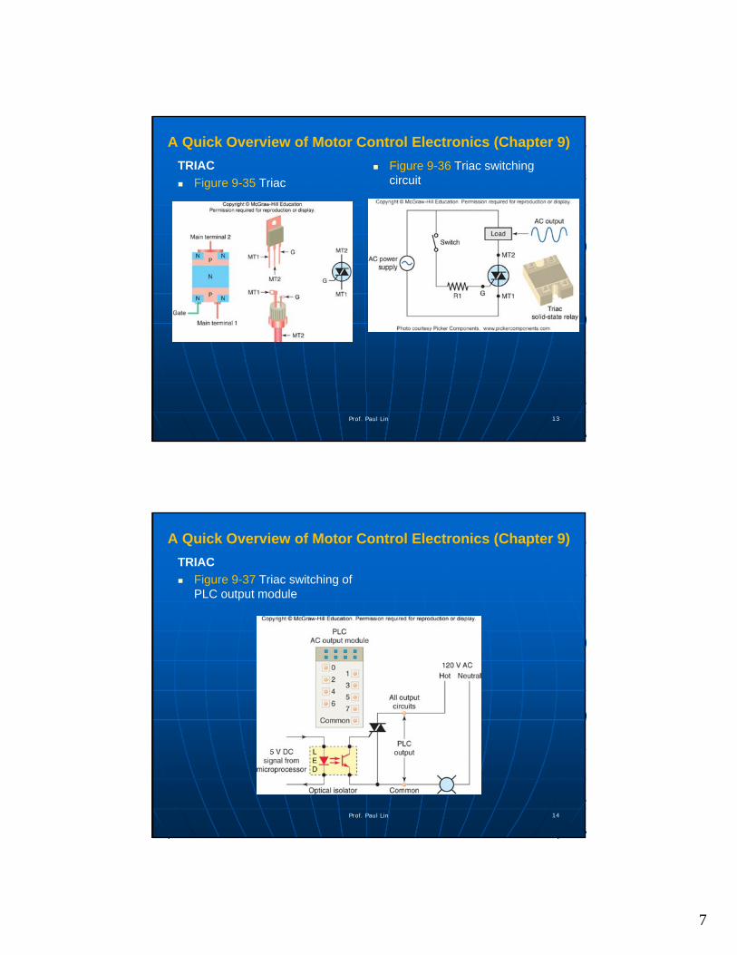
TRIAC
Figure 9-35 Triac
Figure 9-36 Triac switching circuit
A Quick Overview of Motor Control Electronics (Chapter 9)
Prof. Paul Lin 14
TRIAC
Figure 9-37 Triac switching of PLC output module

8
Lecture 9-1 Adjustable-Speed Drives and PLC Installations
The two most important technologies associated with motor control are
• Adjustable speed drives
• Programmable logic controller
Part 1. AC Motor Drive Fundamentals
Primary function of any electronic Adjustable-Speed Drive is to control
• Speed
• Torque
• Acceleration
• Deceleration, and
• Direction of rotation
Prof. Paul Lin 15
Lecture 9-1 (Ch 10) Adjustable-Speed Drives and PLC Installations
Figure 10-1 Variable-speed AC motor drive used for lower-power applications
Prof. Paul Lin 16

9
Lecture 9-1 (Ch 10) Adjustable-Speed Drives and PLC Installations
Figure 10-2 Block diagram of a typical three-phase VFD
Prof. Paul Lin 17
Lecture 9-1 (Ch 10) Adjustable-Speed Drives and PLC Installations
Figure 10-3 Three-phase and single-phase converter input connections
Prof. Paul Lin 18
10
Lecture 9-1 (Ch 10) Adjustable-Speed Drives and PLC Installations
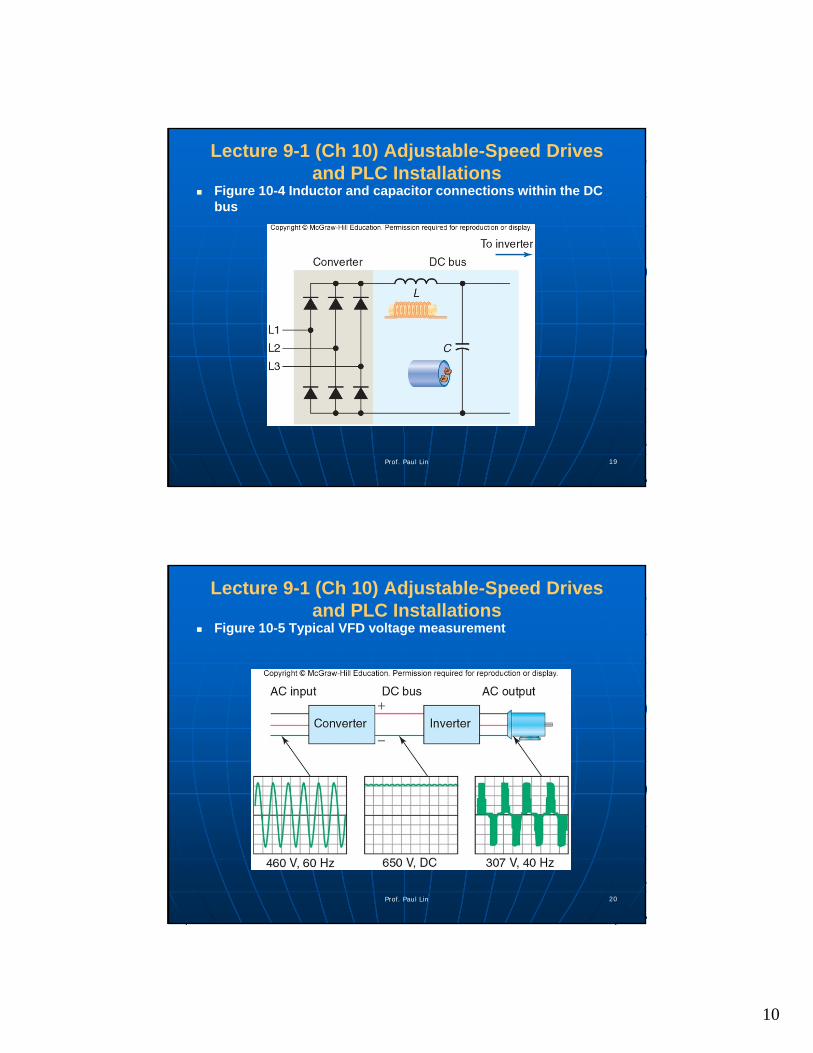
Figure 10-4 Inductor and capacitor connections within the DC bus
Prof. Paul Lin 19
Lecture 9-1 (Ch 10) Adjustable-Speed Drives and PLC Installations
Figure 10-5 Typical VFD voltage measurement
Prof. Paul Lin 20

11
Lecture 9-1 (Ch 10) Adjustable-Speed Drives and PLC Installations
Figure 10-6 The three sections of a variable-speed drive
Prof. Paul Lin 21
Lecture 9-1 (Ch 10) Adjustable-Speed Drives and PLC Installations
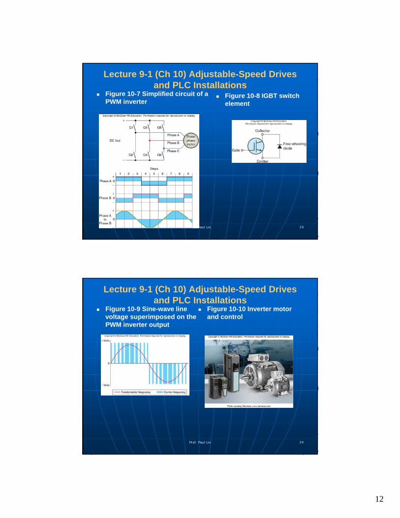
Figure 10-7 Simplified circuit of a PWM inverter
Prof. Paul Lin 22
12
Lecture 9-1 (Ch 10) Adjustable-Speed Drives and PLC Installations
Figure 10-7 Simplified circuit of a PWM inverter
Prof. Paul Lin 23
Figure 10-8 IGBT switch element
Lecture 9-1 (Ch 10) Adjustable-Speed Drives and PLC Installations
Figure 10-9 Sine-wave line voltage superimposed on the PWM inverter output
Prof. Paul Lin 24
Figure 10-10 Inverter motor and control

13
Lecture 9-1 (Ch 10) Adjustable-Speed Drives and PLC Installations
Open Loop vs Closed Loop Control Figure 10-11 Closed-loop control system
Prof. Paul Lin 25
Lecture 9-1 (Ch 10) Adjustable-Speed Drives and PLC Installations
Volts per Hertz Drive (for AC IM) V/Hz = Voltage/Frequency
• An Example: V = 460 volts, F = 60 Hz
• V/Hz = 7.67 apply to any frequency between 0 and 60 Hz
Control principle:
• To maintain constant magnetic flux in the motor, the terminal voltage magnitude must increase roughly to the applied voltage
Horsepower = Torque x Speed x k
• With other refinements:
Low-frequency voltage boost
Steady-state slip compensation
Stability compensationProf. Paul Lin 26

14
Lecture 9-1 (Ch 10) Adjustable-Speed Drives and PLC Installations
Flux Vector Hertz Drive (for AC IM) A vector quantity has both
magnitude and direction
A Flux vector drive controls both the magnitude and direction of the magnetic flux in an AC induction motor.
Figure 10-13 Vector Drives control both magnitude and direction of the magnetic flux
Prof. Paul Lin 27
Lecture 9-1 (Ch 10) Adjustable-Speed Drives and PLC Installations
Flux Vector Hertz Drive (for AC IM) Figure 10-14 Sensorless vector control drive block diagram
Prof. Paul Lin 28

15
Lecture 9-1 (Ch 10) Adjustable-Speed Drives and PLC Installations
Flux Vector Hertz Drive (for AC IM) Figure 10-15 Flux vector drive and encoder
Prof. Paul Lin 29
Summary & Conclusion
Questions?
Prof. Paul Lin 30