east coast railway waltair division · i) system of working : absolute block system ii) block...
TRANSCRIPT

SWR of PARVATIPURAM 1
[CH.B.SRINIVAS] [G.V.S.SARMA]DSTE/WAT Sr.DOM(G)/WAT
EAST COAST RAILWAYWALTAIR DIVISION
No.WTF/5/SWR/PVP Date of issue:Date brought into force:
Ref.Lr.No.2000/Safety (A&R)/19/36 of Rly. Board dt.27.10.05.
STATION WORKING RULES OF PARVATIPURAM STATION PANELINTERLOCKING (BROAD GAUGE)
NOTE: The Station Working Rules must be read in conjunction with General andSubsidiary Rules, Block Working Manual and Operating Manual. These rulesdo not in any way supersede any rules in the above rule books.
1.0 STATION WORKING RULES DIAGRAM:
i) Station Working Rule Diagram No. : SI/WRD/23018 ALT ‘C’
ii) Signal Interlocking Plan : SI/23018 ALT ‘C’
2.0 a) GENERAL (LOCATION):
i) Name of the Station : PARVATIPURAMii) Class of Station : ‘B’ Classiii) Section : Raipur – Vizianagramiv) Double/Single line : Double Linev) Electrified/non electrified : Non-Electrifiedvi) Guage BG/MG/NG : BGvii) Railway : East Coast Railwayviii) Route : ‘B’ Routeix) Situated at KM : 388.857x) From : Raipurxi) No. of Cabins : Centrally Operated Composite miniature domino
type full panel
2.1 DESCRIPTION OF STATION:
Paravatipuram (Code-PVP) is a ‘B’ Class Station on Raipur – Vizianagram Double linenon electrified (BG) section of East Coast Railway on ‘B’ Route. It is situated at KM388.857 from Raipur provided with Centrally Operated Panel Interlocking.

SWR of PARVATIPURAM 2
[CH.B.SRINIVAS] [G.V.S.SARMA]DSTE/WAT Sr.DOM(G)/WAT
2.2 BLOCK STATIONS ON EITHER SIDE AND THEIR DISTANCES & OUTLYING SIDINGS:
The adjacent block stations are SITANAGARAM towards VZM situated at a distance of12.80 KM and GUMADA towards Raipur end situated at a distance of 13.3 KM fromPARVATIPURAM station.
2.3 BLOCK SECTION LIMITS ON EITHER SIDE OF THE STATION ONDEFERENT DIRECTIONS:
Between Station The Point from which theblock section commences
The Point at which blocksection ends.
1. PVP-SNM Dn Line DN Advance Starter of SNM Ends at BSLB of PVP2. PVP-SNM Up Line Commences at Adv Starter 11
of PVP.Ends at BSLB of SNM
3. PVP-GMDA DnLine
Commences at Adv Starter 12of PVP.
Ends at BSLM of GMDA
4. PVP-GMDA UpLine
Up Adv Starter of GMDA Ends at Facing point No 174of PVP.
2.4 GRADIENTS.Chainage in Mtrs.Towards
SITANAGARAMon Up & Dn. lines From To
Stretch inMtrs.
Gradient
All Lines 000.000 17.20 17.20 1 in 580 RaisingUP & DN Line 17.20 563.20 546.00 1 in 1670 RaisingUP & DN Line 563.20 717.20 154.00 1 in 313 FallingUP & DN Line 717.20 1317.20 600.00 1 in 250 FallingUP & DN Line 1317.20 1767.00 450.00 LevelUP & DN Line 1767.00 2317.20 550.00 1 in 245 RaisingUP & DN Line 2317.20 2667.20 350.00 LevelUP & DN Line 2667.20 In to section -- 1 in 150 raising
TowardsGUMADA on UP
& DN Lines.
From To Stretch inMtrs.
Gradient
All Lines 000.000 457.09 457.09 1 in 180 FallingUP & DN Line 457.09 825.51 368.42 1 in 400 FallingUP & DN Line 825.51 855.51 29.60 1in 1000 RaisingUP & DN Line 855.51 1060.80 205.29 LevelUP & DN Line 1060.80 1410.97 350.17 1 in 275 RaisingUP & DN Line 1410.97 1560.22 159.25 LevelUP & DN Line 1560.22 2172.95 612.73 1 in 190 FallingUP & DN Line 2172.95 2950.80 778.30 LevelUP & DN Line 2950.80 In to section -- 1 in 250 Raising

SWR of PARVATIPURAM 3
[CH.B.SRINIVAS] [G.V.S.SARMA]DSTE/WAT Sr.DOM(G)/WAT
2.5 LAY OUT:
i) The Station is provided with four running lines and two non-running line.
Srl No Name of the line Electrified Non Electrifieda) Line no. 1= Common Loop. Non Electrifiedb) Line no. 2= DN Main. Non Electrifiedc) Line no. 3= UP Main. Non Electrifiedd) Line no. 4= UP Loop. Non Electrified
ii) A low level passenger platform of 400 M X 10.70 M is provided for line no.1
ii) A rail level passenger platform of 351.73 M X 7.315 M is also provided on UPLoop.
2.5.1 RUNNING LINES:
The station is provided with four running lines i.e Common Loop [Line No.1], DN main[Line No.2], UP main line [Line No.3], UP Loop [Line No.4].
DIRECTION OF MOVEMENT:
The trains coming from Raipur end proceeding to Vizianagaram are UP trains. Trainscoming from Vizianagaram end proceeding towards Raipur are DN trains.
HOLDING CAPACITIES OF LINES:
Line No.1 [Common Loop] CSL-785 Meters(STR TO STR)Line No.2 [DN Main] CSL-836 Meters(STR TO SB)Line No.3 [UP Main] CSL-771 Meters(STR TO SB)Line No.4 [UP Loop] CSL-752 Meters(STR TO SB)
2.5.2 NON-RUNNING LINES AND THEIR CAPACITY:
Nil
2.5.3 ANY SPECIAL FEATURE IN THE LAYOUTNil
DESCRIPTION OF SIDINGS – HOT AXLE SIDING:-
One hot axle siding is taken off from line No.1 at GUMADA end of the yard and iscontrolled by Button No 27 and the CSL is 95 Mtrs[Block Joint to Dead end].

SWR of PARVATIPURAM 4
[CH.B.SRINIVAS] [G.V.S.SARMA]DSTE/WAT Sr.DOM(G)/WAT
2.6 LEVEL CROSSINGS:
The detailed working of the L.C. Gates along with the particulars are mentioned inAppendix ‘A’
3.0 SYSTEM AND MEANS OF WORKING:
i) System of working : Absolute Block Systemii) Block Instrument : ‘SGE’ type Double line block instrument are
provided for block sections, PVP-GMDA &PVP-SNM.
iii) Co-operative/Non Co-operative : Non Co-operativeiv) Custody of keys of Block
instrument: Block instrument is provided with doublelocking. One key will be with SM and alter keywill be with S&T maintains.
4.0 SYSTEM OF SIGNALING AND INTERLOCKING:
4.1 a) Standard of Interlocking : The Station is provided with Standard –IIIInterlocking.
b) Type of Signals : Multiple Aspect Color Light Signals. Theaspects & indication of the MACLS is governedby GR3.08(4)(b)
c) The Station is provided withpanel interlocking.
: The points & singals one operated from thispanel.
d) Method of operation : A centrally operated panel is installed in SM’soffice.
e) TRACK CIRCUITS AND AXLE COUNTERS:
Both Up and Down Main lines Common loop & UP loop are provided withBerthing Track circuits as,
Up main line: UMT 1, UMT 2, UMT 3 Down main line: DMT 1, DMT 2, DMT 3 Common loop: L1T1, L1 T2 & L1 T3. UP loop: L4T1, L4T2, and L4T3. Point zone track circuits are also provided as 18/AT, 18/BT, 20AT, 20BT,
22AT, 22BT, 17AT, 17BT, 19AT, 19BT, 21T. 1AT and 2AT are the approach track circuits for up and down calling on
signals respectively. Up Block release track circuits as 1T, 1T1 Dn Block release track circuits as 2T, 2T1 . Up Advance starter approach and replacement track circuits as 11AT & 11T
respectively.

SWR of PARVATIPURAM 5
[CH.B.SRINIVAS] [G.V.S.SARMA]DSTE/WAT Sr.DOM(G)/WAT
DN Advance starter approach and replacement track circuits as 12AT & 12Trespectively.
3T1 & 3T2 Track circuits are provided for control and replacement of gatehome singal 3GF of “A” Class L.C. Gate at KM.387/7-8.
The demarcation of track circuit portion is indicated on operating cum indication panel.Only when any running line is clear and initiated a white strip of lights illuminated on thepanel through out the line so initiated. However when running line occupied by anyvehicle/Train a RED strip of lights illuminate through out the berthing line till such timeit is cleared.
FAILURE OF TRACK CIRCUITS:
In the event of failure of track circuits before permitting any movement on such trackcircuited portion SS/Dy.SS on duty shall ensure that portion of track is clear by sendingTPM/TP on duty or shall personally verify when feasible. In the event when TPM is sentto this effect the clearance shall be ensured from the TPM supported by private number.
AXLE COUNTER:
1] Axle counter for last vehicle check is provided for the following sections.A] PARVATIPURAM-SITANAGARAM [UP LINE]B] PARVATIPURAM-GUMADA [DN LINE]
Resetting arrangement is provided in the SM’s panel when ever the Axle counter zoneshows occupation even after any movement is completed or due to failure of Axle counterequipment. In such cases, the Axle counter is to be reset the process of which detailed inAppendix ‘B’ is to be followed.
i) All running line points are Motor operated by Electric Point Machines whichhave got in built locking and detection arrangement.
ii) For emergency operation of Electric Point Machines, Crank Handles areprovided and are interlocked with the system.
CRANK HANDLE:
When any Motor point has failed to operate from panel, it is inevitable to operate bymeans of crank handle. To achieve this these Crank handles accessibility keys areprovided at the respective ends in the available gate lodges near to points zones formanual setting with a telephone facility.
The crank handles accessible keys at the respective ends of the yard in the available gatelodges are released by the operation of control push button by the on duty SS/Dy.SS.Refer to Appendix ‘B’ regarding setting of points by crank handle.

SWR of PARVATIPURAM 6
[CH.B.SRINIVAS] [G.V.S.SARMA]DSTE/WAT Sr.DOM(G)/WAT
CALLING ON SIGNALS:
Miniature calling on signals are provided below UP & DN Home signals in terms of GR3.13[6],[B]. Calling on signal is taken off for reception of trains when the Home signalabove it can not be taken off due to failure or any other reason or for admission of trainon to a stocked line.[Details of Signalling and Interlocking given in Appendix ‘B’].
4.2 CUSTODY OF RELAY ROOM KEY AND PROCEDURE FOR ITS HANDINGOVER AND TAKING OVER BETWEEN SS/DY.SS AND S&T MAINTENANCESTAFF:
Double locking [i.e. two independent locks] arrangements for the relay rooms is provided.Out of two such locks, one lock’s key shall be in the personal custody of the SS/Dy.SS onduty and the other key shall be kept with S&T maintainer. When ever key required by themaintainer the SS/Dy.SS on duty shall hand over the key to the maintainer under clearendorsement in relay room key register about the reason for requirement of key. Oncompletion of the work the key shall be returned back to SS/Dy.SS on duty. All the abovetransactions shall be recorded in the relay room key register vide OM 1.14[b].
4.3 POWER SUPPLY:
Power signaling and interlocking installations and the satellite ancillary field units are fedfrom the following sources of power supply.
i) Normal supply from APSEB supply .
ii) Stand by supply – 2 No of Diesel Generator Sets of capacity 15KVA. Provided in theDG room with changeover arrangement.
5.0 TELECOMMUNICATION:
i) Telephone attached to SGE Type lock and block instrument connected to theadjacent stations on either side.
ii) Magneto phone is provided between Station and L.C.gate at KM 389/7-8, 387/7-8and 382/8-9.
iii) Magneto Phone is provided for sections PVP-SNM and PVP- GMDA.
iv) Railway Auto Tele phone
v) BSNL Telephone
vi) The station is connected to VZM-tieline ‘B’ cabin control phone.

SWR of PARVATIPURAM 7
[CH.B.SRINIVAS] [G.V.S.SARMA]DSTE/WAT Sr.DOM(G)/WAT
6.0 SYSTEM OF TRAIN WORKING:
Movement of trains is regulated by the Section Controller on duty whose orders must becarried out provided they do not contravene any G&SR, BWM, OM, SWR or any othersafe working principles. In the event of suspension of control working, the SS/Dy.SS onduty shall work independently in consultation with the SS/Dy.SS of the adjacent blockstation and shall be responsible for reception and dispatch of train. He shall ensure thatpreference is given to important trains and at the same time no undue detention occurs toother train.
6.1 DUTIES OF TRAIN WORKING STAFF:
The duties of train working staff are mentioned in detail in Appendix-‘D’.
6.1.1 TRAIN WORKING STAFF & COMPLEMENT OF STAFF
Complement of Staff Staff in each ShiftSS - 1 SS - 1 (Day Shift)Dy.SS - 2 Dy.SS/SM - 1 in each shiftSM - 3 Traffic Point - 1 in each shiftTraffic Point - 5 TGG - 1 in each shiftTGK - 3 SCLM - 1SCLM - 1
NOTE: Staff deployed at this station shall follow the rosters issued by DPO/WAT fromtime to time.
6.1.2 RESPONSIBILITY FOR ASCERTAINING CLEARANCE OF THE LINES ANDTHE ZONES OF RESPONSIBILITY:
The SS/Dy.SS on duty is responsible to nominate clear line that is free from allobstructions from the Home signal to the Starter signal inclusive of adequate distancebeyond it for admission of trains vide 3.40(1)(a), 3.40(3)(b).The clearance of the running line for the reception of the train is to be verified by theSS/Dy.SS on duty by verifying luminous indication provided on the panel board.
6.1.3 ASSURENCE OF STAFF IN THE ASSURENCE REGISTER:
All staff who are in any way connected with trains passing duties, shall before beingallowed to take-up independent charge of their duties and after absence of 15(Fifteen)consecutive days or more, and if there is any change made in the Station Working Rules,shall sign in the Assurance Register as a token of their having gone through andunderstood clearly the rules in connection with their duties vide SR 5.01.02.

SWR of PARVATIPURAM 8
[CH.B.SRINIVAS] [G.V.S.SARMA]DSTE/WAT Sr.DOM(G)/WAT
The SMR in-charge of the station shall be personally responsible for maintenance ofAssurance Register and must not allow any person connected with train passing dutiesto work independently unless he has given his assurance as per SR. 5.01.02.
6.2 CONDITIONS FOR GRANTING LINE CLEAR:
The conditions laid down in GR 8.01(1)(a) & (b), 8.01(2)(b) & 8.03 (1)(a), (b) and(c)(ii), G.R.14.10, BWM 5.08 & 5.09(2) shall be complied with before the line isconsidered ‘Clear’ and the ‘Line ‘Clear’ is granted.
Note: If the light of the reception signal is found not lit up, line clear shall not begranted for train till such time it is ensured that the concerned loco pilot is notified ofthe fact in writing by the SS/Dy.SS of the station to which such line clear is to begranted vide GR3.49[4].
6.2.1 SPECIAL CONDITIONS TO BE OBSERVED WHILE RECEIVING ORDESPATCHING A TRAIN:
6.2.1.1 SETTING OF POINTS AGAINST BLOCKED LINE
When a running line is blocked by a stabled load, wagon, Vehicle or by a train is tocross or give precedence to another or immediately after the arrival of the train at thestation etc, the points at either end should be immediately set against the blocked lineexcept when shunting or any other movement is required to be done on that line. If allthe lines of a station happen to be blocked when line clear has been granted to a train thepoints should be set for the line occupied by a stabled load or a goods train in that orderso that, in case of mislap the chance of causalities are minimized. In case of all the linesare occupied by passenger train, points should be set for a loop line to negotiate withthe speed of incoming train would be reduced which in turn, would minimize theconsequences/causalities.
6.2.1.2 RECEPTION OF TRAIN ON BLOCKED LINE:
Under unavoidable circumstances, whenever trains are to be admitted on an obstructedline, it is necessary that the trains are piloted ‘IN’ on a written authority given by theStation Master on duty and delivered by a competent Railway servant to the driver ofthe train or by taking ‘OFF’ of calling ‘ON’ signal and the rules laid down in GR 5.09and SRs 5.09.01 and GR 3.69 shall be followed.
6.2.1.3 RECEPTION OF TRAIN ON NON-SIGNALLED LINE:
Reception of trains on a non signaled line is governed by GR 5.10 and SR 5.10.01.
6.2.1.4 DESPATCH OF TRAIN FROM NON-SIGNALLED LINE:
Despatch of trains from non signaled line is governed by GR.5.11 and SR 5.11.1

SWR of PARVATIPURAM 9
[CH.B.SRINIVAS] [G.V.S.SARMA]DSTE/WAT Sr.DOM(G)/WAT
6.2.1.5 DESPATCH OF TRAIN FROM LINE PROVIDED WITH COMMONSTARTER SIGNAL:
To dispatch a train from common loop GR 5.12 and SR 5.12.1 shall be observed.
6.2.1.6 ANY OTHER SPECIAL CONDITIONS SHOULD BE MENTIONED GIVINGREFERENCE TO THE G&SR:
SPECIAL RESTRICTIONS.
When ever a train whose section speed is 100Kmph or above was required to be stoppedat the station out of course, it shall be first brought to a stand out side first stop signaland shall then be admitted. SS/Dy.SS on duty shall exhibit a Red signal to the driver atthe station.
SPECIAL INSTRUCTIONS:Nil
6.3 CONDITIONS FOR TAKING OFF APPROACH SIGNALS:
The conditions for taking off approach signals shall be governed by GR 3.40(1)(a),3.40(2)(a), 3.40(3)(b) and relevant SRs thereto.
6.3.1 RESPONSIBILITY OF SS/Dy.SS FOR RESTORATION OF SIGNALS TO ON:
SS/Dy.SS shall ensure that the signal is gone back to ‘ON’ after passage of a train as perGR 3.36 [2][b].Up & Dn Home, Starters, Advance Starters signals will go back ON position afteroccupation of particular track circuits. SS/Dy.SS on duty shall send TRAIN OUT OFBLOCK SECTION report to the station in rear in terms of GR 14.01 and SR 4.17.01.
6.4 SIMULTANEOUS RECEPTION/DESPATCH, CROSSING & RECEDENCE OFTRAINS:
The interlocking at the Station permits the following simultaneous reception anddespatch of trains:6.4.1Reception of an Up train on lineno. 1
And Despatch of another UP train from lineNo.3(UP main) or from line No. 4
Reception of a DN train onCommon loop(Line no.1)
And Despatch of another DN train from lineNo.2.
Reception of a UP train on lineno.4[UP loop]
And Despatch of another UP train from lineno.1(Common loop) or from lineNo.3(UP Main)

SWR of PARVATIPURAM 10
[CH.B.SRINIVAS] [G.V.S.SARMA]DSTE/WAT Sr.DOM(G)/WAT
CROSSING OF TRAINS:
Being a double line section crossing of trains does not arise at this station.
PRECEDENCE OF TRAINS:
Precedence of trains is controlled by SCR and CHC coaching .
RECEPTION OF TRAINS:
Reception of trains is governed by rules laid down in GR 3.36, 3.38, 3.40, 3.49 & 4.17and SRs thereto & SRs 3.42.02 [iv] & 3.42.03 and other relevant provisions of G&SR,BWM, OM and SWR shall be followed.‘B’ Class traffic Level Crossing gate at KM 389/7-8 at SNM end of the yard and ‘A’Class Engg Level Crossing gate at KM 387/7-8 at GMDA end of the yard are sointerlocked with station stop signal that unless the gate is closed locked and key istransmitted to SS/Dy.SS on duty, the signals cannot be taken off for UP and DN trains.
PUTTING BACK OF SIGNALS:
Up & Dn Home, Starters, Advance Starters signals will go back ON position afteroccupation of particular track circuits. SM on duty shall send TRAIN OUT OF BLOCKSECTION report to the station in rear in terms of GR 14.01 and SR 4.17.01.
CONDITIONS FOR TAKING OFF APPROACH SIGNALS:
The conditions for taking off approach signals shall be governed by GR 3.40(1)(a),3.40(2)(a), 3.40(3)(b) and relevant SRs thereto.
ADEQUATE DISTANCES
To take off the Home Signals for admission of a train, the adequate distance [SignalOverlap] as mentioned below shall be kept clear in terms of GR 3.40 (1) (a) and SRthereto.
CLEARANCE OF ADEQUATE DISTANCE
LINE No. For Up Trains For Down Trains
From To From ToLine no. 1(CommonLoop)
Up Starter signalno. 7
End of Sandhump or up toAdv Str.No.11.
Dn Str SignalNo.6
End of Sandhump or DNAdv Str. SignalNo.12

SWR of PARVATIPURAM 11
[CH.B.SRINIVAS] [G.V.S.SARMA]DSTE/WAT Sr.DOM(G)/WAT
LINE No. For Up Trains For Down Trains
From To From ToLine no. 2(DN Main)
-- -- Dn Str SignalNo.10
DN Adv Str.Signal No.12
Line no. 3 (UP.Main)
UP Str. SignalNo.9
Up Adv. Str.Signal No:11
-- --
Line no. 4 (UPLoop)
UP Starter signalNo. 5
End of sandhump or UpAdv.Str. SignalNo.II
-- --
COMPLETE ARRIVAL OF TRAINS
The entire block section between PVP-GMDA & PVP-SNM on both UP and down linesare monitered by axle counter system. Complete arrival of the train can be ensured bythe indication of Last Vehicle Check device provided on panel. The position of blocksection whether occupied or clear is indicated on the panel. If the panel still continues toshow red or if there is any LVCD failure, SS on duty shall obtain Complete ArrivalCertificate from the guard in the Complete Arrival Register (T/410) maintained at htstation for stopping train. In case of through passing trains, the SM on duty shall satisfyherself the complete arrival of the train by verification of Last Vehicle indictor vide SR4.16.05 that the train has arrived complete.
DESPATCH OF TRAINS:
Despatch of trains is governed by provision of GR 3.42 and SR thereto, SR 3.36.04SR.3.42.02 (IV), SR 3.42.03, SR 3.42.04 and BWM 2.07(5) (a), (e), (f)&(g) and otherrelevant provision of G & SR, BWM and SWR.
The SS/Dy.SS on duty, after obtaining line clear for the concerned train, shall firstsuspend all non-isolated shunting and shall withdraw the shunting authority issuedearlier and kept in his possession. SS/Dy.SS on duty shall also ensure closing andlocking of L.C Gate Non interlocked from Gateman supported by private number andalso ensure the closure of interlocked L.C gate and get the key transmitted from the gateman.
TRAIN ENTERING BLOCK SECTION:
The SS/Dy.SS on duty after verifying that the train has passed past the advanced startersignals (Both physically & through Panel indications) shall send the TRAINENTERING BLOCK SECTION Signals vide BWM 2.07.5(a).

SWR of PARVATIPURAM 12
[CH.B.SRINIVAS] [G.V.S.SARMA]DSTE/WAT Sr.DOM(G)/WAT
ISSUE OF CAUTION ORDERS:
Whenever in consequence of the line being under repairs or for any other reasonsspecial precautions are necessary a Caution Order detailing the Kilometers and Speed atwhich train should run with reasons for taking such precautions shall be handed over tothe Guard and loco pilot in terms of GR 4.09 and SR thereto.
TRAINS RUNNING THROUGH
i) In addition to procedure detailed in paras ’Reception and Dispatch’ of trains,rules laid down in GR 4.17, 4.42, 3.36, 3.42 with relevant SRs shall be followed.
ii) Reception and despatch signals shall be taken “OFF” for a through train as perthe sequence given below vide SR 3.42.02(a)(iv), SR 3.42.03 and SR 3.42.04.
iii) In every case in which trains are permitted to run through on non-isolated line, allshunting shall be stopped and no vehicle unattached to an engine or not properlysecured in accordance with rule GR 5.23 may be kept standing on a connectedline which is not isolated from through line.
iv) The SS/Dy.SS shall see that the last vehicle of every train passing through hisstation is provided with a tail board or a tail lamp or such other device inaccordance with the provision of the GR 4.16 and SR 4.17.01(a).
6.8 WORKING IN CASE OF FAILURE:
a) Track Circuit/ Axle Counter’s
In case of failure of track circuit, the clearance of the concerned line should beconcerned line should be ensured physically before a train is piloted.If the axle counter fails between the block section, resulting procedure will beadopted as per para of SWR (Appendix-‘B’). if axle counter indication does notappear ‘Green’ and continues to show ‘Red’ condition after resetting theconcerned block section shall be suspend & failure indication to be given toSectional Signal Maintainer / JE/SE/Signal for ratification.
b) Block Instruments
In the event of partial/ total failure of block instrument the concerned blockinstrument shall be suspend till is rectification & trains shall work as per SR6.02.03 & 6.02.06).During the period of time the authority will be T/369(b) with identification no &private no. issued from the station in advance written both in figure of words.

SWR of PARVATIPURAM 13
[CH.B.SRINIVAS] [G.V.S.SARMA]DSTE/WAT Sr.DOM(G)/WAT
c) DEFECTIVE SIGNALS:
When Signals become defective, the procedure laid down in GR 3.68 to 3.71 andSRs thereto shall be followed. A Signal in the OFF position is the final indicationthat the points are correctly set and locked for the route for which it applies and ifit is found impossible to take OFF a signal, the setting of points on the route towhich it applies shall be inspected by the SS/Dy.SS before the signal is declaredas defective vide SR 3.68.01(c) In case of disconnection of signaling andinterlocking gears for repairs and maintenance, procedure laid down in GR 3.51,3.68 and relevant SRs shall be followed.In the event of signal showing no lights, and if signal lights can not be keptburning, SS/Dy.SS on duty shall before giving line clear’ initiate action inaccordance with the procedure prescribed in GR 3.49(4).
d) DEFECTIVE INTERLOCKING:
When interlocking becomes defective, the SS/Dy.SS on duty shall be responsibleand personally supervise the setting, clamping and padlocking of all requiredfacing and trailing points for admission of a trains, vide 3.69.03(c).
e) INSPECTION OF POINTS BEFORE DECLARING THEM DEFECTIVE:
However, before declaring a signal is defective, the setting of the points on theroute to which it applies shall be inspected by the SS/Dy.SS irrespective of theposition of the points in terms of SR 3.68.01[c] and GR 3.68,3.70,with relevantSRs and SR.3.77.01 (b) shall be followed.
f) DEFECTIVE OR DAMAGED POINTS:
When points become defective, the signals controlling these points shall beconsidered as defective and vice-versa and action to be taken as prescribed underGR 3.77 relevant SR’s thereto. The SS/Dy.SS is the in-charge of S&Tinstallations at his station and shall ensure efficient discharge of the dutiesdevolving on the S&T maintenance staff. To this extant he shall satisfy himselfthat both ESM/ MSM who visit the station have done proper oiling, cleaning andadjustments as necessary of the signaling and interlocking apparatus and afterensuring this, the SS/Dy.SS shall sign the diary indicating the conditions of thegear as stipulated in the maintainer’s diary. The SS/Dy.SS is also responsible fortesting of Points and signals as stipulated in SR 5.01.03.
PILOTING OF TRAINS-INTO STATION YARD
i) Piloting of the trains into the station yard is governed by SRs 3.69.02 and3.69.03.

SWR of PARVATIPURAM 14
[CH.B.SRINIVAS] [G.V.S.SARMA]DSTE/WAT Sr.DOM(G)/WAT
ii) Whenever Home signal has become defective the calling ‘ON’ signal belowit shall be taken off in items of SR 3.69.02
iii) Whenever Home signal and the calling ‘ON’ signal below it have becomedefective, the SS/Dy.SS On Duty shall advise the station in rear to issuewritten authority to this effect and the procedure laid down in SR 3.69.02(a) shall be followed.
PILOTING OF TRAINS -OUT OF STATION YARD:
Piloting of trains out of the Station yards is governed by GR 3.70 and SRsthereto.
NOTE: The responsibility for Correct setting and locking of points as also itsclearance of line in respect of all trains shall devolve personally on the SM onduty according to SR 3.69.03 (c).
6.9 PROVISION FOR WORKING OF TROLLIES/MOTOR TYOLLIES/MATERIAL LORRIES:
Motor trolleys shall be worked as per GR 15.25 & SR thereto and BWM 5.11(2), 5.12,5.13 and 5.14(2)(b) and Circulars & Orders issued from time to time. Material trolleysshall be worked as per GR 15.27 and SRs thereto and BWM 5.11(2), 5.13.
7.0 BLOCKING OF THE LINES:
Whenever a running line is blocked either by loose vehicles or by stabling train or by atrain which is to cross or give precedence to another train, the points at either end shouldimmediately be set against the blocked line except during shunting movement. ‘LineBlock’ is to be activated on VDU by Dy. SS/SM on duty following procedures as laiddown in para no. 6.2.2. A clear remark in ‘RED’ ink shall be made immediately in thetrain signal register and a record shall be made in the Station Master’s diary also.Stable load register is also to be maintained. The stable load or loose vehicles are to besecured to prevent rolling down of vehicles. [Refer SR 3.36.3(b), GR 5.23,SR5.04.01(a) and SR 5.23.01(a)]
7.1 LOADING AND UNLOADING OF VEHICLES ON RUNNING LINES:
Except smalls, loading and unloading of vehicles on running line is prohibited unlesspermitted by DOM vide SR 5.19.01.

SWR of PARVATIPURAM 15
[CH.B.SRINIVAS] [G.V.S.SARMA]DSTE/WAT Sr.DOM(G)/WAT
7.2 SECURING OF VEHICLES:
The rules laid down in GR 5.23, SR 5.23.01and OM 7.08 shall be followed.NOTE: Special care shall be taken to secure special type vehicles fitted with rollerbearings while standing in siding or running lines vide SR 5.23.01(b).
7.3 DETACHING OF VEHICLES ON RUNNING LINES:
Detaching of vehicles on running lines is normally prohibited. Whenever any vehicle isdetached on running lines under unavoidable circumstances such rolling stock shall beplaced opposite to the Station Master’s office as far as possible and shall be properlysecured vide SR 5.23.01 and 5.19.01(d).
8.0 SHUNTING
i) The rules laid down in GR 3.46, 3.52 to 3.56, 5.13 to 5.23, 8.05(2) (3), 8.06 and8.14, 8.15 (c) with relevant SRs and OM 7.01, 7.07 and 7.08 shall be observed.All shunt moment shall be supervised by Guard/SS/Dy.SS, point man on dutyvide SR 5.13.03 as the case may be.In the event of any non-signaled movement has taken place, the Dy.S.S/SS. onduty shall ensure physical verification of the clearance of the crossover points.
ii) CUSTODY OF KEYS AND PAD LOCKS DURING SUCH MOVEMENT:
The key of the pad locks of such points shall be in the personal custody of theoperating official vested with this responsibility till such time movements arecompleted The operating official vested with the responsibility of supervising theNon-signaled movement of the engine/train/vehicle must return the key alongwith pad locks to the SS/Dy.SS on duty, after completion of the said movementor alternatively when such a move is cancelled.
iii) AUTHORITY FOR SHUNTING OPERATIONS:
The SS/Dy.SS on duty shall issue written shunting authority on from T/806 to theLoco Pilot through guard of the train when the non signalled shunting is resortedto.This memo shall be with drawn whenever shunting is to be suspended forreception and dispatch of train if the line on which shunting is performed is notisolated. After shunting is completed, the order shall be collected from the Drivercancelled and pasted with the record foil as per SR 5.13.02.
Note:Points both facing and trailing are to be clamped and padlocked for all non-signaled movements. Further it must be ensured that the Entrance and Exit trackcircuit are clear as also the intervening track of the cross over is clear of any
SWR of PARVATIPURAM 16
[CH.B.SRINIVAS] [G.V.S.SARMA]DSTE/WAT Sr.DOM(G)/WAT
obstruction and certified so by the operating official (who is responsible forshunting supervision) before the SS/Dy.SS on Duty resumes normal workingeither for reception or dispatch of trains in to the station yard or through thestation yard.
iv) NON-SIGNALLED MOVEMENTS:
All signaled movements in the yard either of train or of an engine with or withoutvehicles shall be from one stop signal to the next stop signal or stop board and nohalf way movements are permitted and if such movements are unavoidable itshould be considered as non-signaled move and precautionary measures shouldbe taken such as clamping and pad locking of points on the route both interlockedand non-interlocked points including derailing switches according to SR 5.3.05and 5.14.03.
8.2 SHUNTING IN FACE OF AN APPROACHING TRAIN:
Strictly prohibited.
8.3 PROHIBITION OF SHUNTING ANY SPECIAL FEATURES IF ANY:
a) Hand shunting /Fly shunting is prohibited at both ends of the yard.
b) Shunting shall not permitted at South end of the yard unless the Engine isleading towards the falling gradient vide GR.5.20
8.4 SHUNTING ON SINGLE LINE:
Not applicable.
8.5 SHUNTING ON DOUBLE LINE:
i) When the line clear has been given no shunting shall be permitted in the blocksection in rear Vide GR 8.06 (1).
ii) Shunting or obstruction for any other purpose shall not be permitted in the blocksection in rear unless it is clear and is blocked back Vide GR 8.06(2) and BWM5.15[I][b].
iii) Shunting or obstruction for any other purpose shall not be permitted in the blocksection in advance unless it is clear and is blocked forward Vide GR 8.06(3)andBWN 5,15[2][b].

SWR of PARVATIPURAM 17
[CH.B.SRINIVAS] [G.V.S.SARMA]DSTE/WAT Sr.DOM(G)/WAT
8.6 SHUNTING IN THE SIDING TAKING OFF FROM THE STATION YARD :
While performing shunting in the sidings it should be authorised by issuing T/806clearly mentioning the limits up to which shunting is permitted as also the lines,occupied in shunting. The relevant provisions of GR 5.14 and SR thereto shall bemeticulously followed.
8.6.1 a) SHUNTING OUTSIDE STATION SECTION:-
i) Shunting shall not be permitted in block section (i.e., in the block section in rear )unless it is clear and is blocked back.
ii) Shunting shall not be permitted in block section in advance unless it is clear andis blocked forward.
b) SHUNTING OUTSIDE STATION SECTION :
i) The line outside the station section and upto the Home Signal shall not beobstructed unless a Railway servant specially appointed in his behalf by theSS/Dy.SS who is in-charge of the operations, and unless –
ii) The block section into which the shunting is to take place is clear of anapproaching train and all relevant and necessary signals are kept “ON” position.
c) SHUNTING WITHIN STATION SECTION :
If the necessary signals are kept at “ON”, shunting may be carried on within thestation section vide GR 8.05[2].
9.0 ABNORMAL CONDITIONS:
a) i) THE RULES TO BE OBSERVED IN EVENT OF ABNORMALCONDITIONS:
During partial interruption/failure of electrical communication instrument. In theevent of partial interruption of communication the trains shall be worked in termsof SR 6.02.06.
ii) ISSUE OF THE BLOCK TICKET :
Rules and regulations for working trains on an obstructed line in case ofobstruction or accident on the authority of block tickets (T/A 602) whencommunications are available shall be followed in accordance with the provisionsof SR 6.02.05.

SWR of PARVATIPURAM 18
[CH.B.SRINIVAS] [G.V.S.SARMA]DSTE/WAT Sr.DOM(G)/WAT
iii) TRAINS DELAYED IN BLOCK SECTION:
In the event of trains unusually delayed in the block section, the action shall beinitiated as per GR 6.04 and SR thereto.
iv) FAILURE/PASSING OF INTERMEDIATE BLOCK STOP SIGNAL ATON:
No IBS are provided.
v) FAILURE OF AXLE COUNTER BLOCK/BPAC;
In the event of failure of Axle counter[BPAC] between GMDA-KNRT andGMDA-PVP train shall not be allowed until complete arrival of preceding train isascertained physically or ensured from the guard by obtaining certificate on traincomplete arrival register on form No;T/1410. Resetting process is given inAppendix ‘B’.
b) PROCEDURE FOR EMERGENCY OPERATION OF POINTS BYCRANK HANDLE:
Crank handle accessible key is inter locked with the signaling and inter lockingsystem at this station and the crank handle key which is normally locked up in theRKT instrument in the goomties/crank handle locations at the both End of theyards can be taken out when the signals on the connected route are in normalposition and the route is not locked for any reason.Even when the route is locked the crank handle key can be extracted from theRKT through emergency operation by pressing the concerned crank handlebutton along with group Trans button concurrently.When this operation is resorted, the crank handle ‘Key in’ indication(white) andlocked indication (Red) both start flashing on panel. After 120 Seconds offlashing the locked indication (Red) disappears. Similarly such red indicationappears at the crank handle location at site near corresponding RKT and then thecrank handle accessible key can be taken out from the RKT at site, After key isextracted at site from the RKT, the key in indication (white) on panel, board willextinguish. After completion of work, crank handle key shall be restored to RKTwhich will be indicated by flashing key in (white) indication on panel board,which comes steady only after pressing of concerned crank handle button alongwith group release button concurrently.
c) CERTIFICATION OF CLEARENCE OF TRACK BEFORE CALLINGON SIGNAL OPERATION IS INITIATED:
Before taking off calling on signal the Clarence of the portion of the line on towhich the train is to be admitted, is to be ensured by on duty SS/Dy.SS.

SWR of PARVATIPURAM 19
[CH.B.SRINIVAS] [G.V.S.SARMA]DSTE/WAT Sr.DOM(G)/WAT
d) REPORTING FAILURE OF POINTS, TRACK CIRCUIT/AXLECOUNTER AND INTERLOCKING:
i) Whenever there is a failure of points, signals, track circuits/axle counter andinterlocking gear at this station which includes level crossing gate if any ,etc, thefailure report should be communicated by the SS/Dy.SS on duty through a memoto the maintainer and the SSE/SE/JE along with others as per GR 3.51.04,3.68.04 and document all such transactions. Only after receipt of the writtenmemo from the signal maintainer after rectification of the fault , SS/Dy.SS shallrestore the normal working.
ii) The entries in the failure register to be done with message to the sectioncontroller.
9.1 TOTAL FAILURE OF COMMUNICATIONS:
In the event of single line working on a double line section during total failure ofcommunication the provisions laid down in SR 6.02.02 shall be followed.During the total failure of communications on double line trains shall be worked inaccordance with the provision of SR 6.02.03.
TEMPORARY SINGLE LINE WORKING ON DOUBLE LINE SECTION:
Temporary single line working on a Double line section.
i) In the event of single line working being introduced when communications areavailable the provisions laid down in SR 6.02.01 shall be followed.
ii) During partial interruption of communication the procedure detailed in SR6.02.06 shall be followed.
9.3 DESPATCH OF TRAINS UNDER AUTHORITY TO PROCEED WITHOUTLINE CLEAR:
i) During the total interruption of communications, while allowing the trains underauthority to proceed without line clear the relevant provisions under SR 6.02.02and SR 6.02.03 as the case may shall be followed.
ii) The last stop signals shall not be taken “OFF” but an authority to pass the laststop signal at “ON” in prescribed form T/C 602 shall be issued.

SWR of PARVATIPURAM 20
[CH.B.SRINIVAS] [G.V.S.SARMA]DSTE/WAT Sr.DOM(G)/WAT
RUNNING TIME OF TRAINS UNDER AUTHORITY TO PROCEEDWITHOUT LINE CLEAR[T/C.602].
Section Distance Running time duringday and view ahead inclear at 25 KM PH..
Running time during night,thick foggy tempestuousweather or when view ahead isnot clear at 10 KM PH.
PVP-SNM 12.8 KM 30.72 mnts 76.8 mnts.PVP-GMDA 13.3 KM 31.92 mnts 79.8 mnts
RUNNING TIME OF TRAINS UNDER AUTHORITY TO PROCEED WITHOUT LINE CLEAR[T/B.602]
Section Distance Running time duringday 15 KM PH..
Running time during night,thick foggy tempestuousweather or when view ahead isnot clear at 10 KM PH.
PVP-SNM 12.80 KM 51.2 mnts 76.8 mnts.PVP-GMDA 13.3 KM 53.2 mnts 79.8 mnts
10. VISIBILITY TEST OBJECT:
The signal lights of UP starter signal No.9 of UP line and DN starter Signal No.10 ofDN main line during day and night are the visibility test objects vide GR 3.61[2][b][iii].
11.0 ESSENTIAL EQUIPMENT AT THE STATION:
The list of essential equipment is given in Appendix ‘E’ which shall be maintained ingood working order vide OM 20.04[11].
FOG SIGNAL MEN NOMINATED TO BE CALLED IN CASE OF FOG:
In Foggy of tempestuous weather or in dust storm when V.T.O cannot be seen from theStation building, the SS/Dy.SS shall send trained men to act as for signalmen. The ruleslaid down in GR 3.61 and 3.64 with relevant SRs shall be followed. In case of
a) Visibility test object specified in item No.10 above in terms of GR.3.61[2][b][I].
b) When due to foggy or tempestuous weather or dust storm, the station V T O cannot be seen, the SS/Dy.SS on duty shall send the trained fog signal men withsufficient numbers of valid detonator, hand signals to act as fog signal men videSR.3.61.01[d].

SWR of PARVATIPURAM 21
[CH.B.SRINIVAS] [G.V.S.SARMA]DSTE/WAT Sr.DOM(G)/WAT
c) SS/Dy.SS shall select some of the traffic staff and some engineering staff drawnfrom engineering branch and council the use of fog signals and take theirassurance in the part I of fog signal register in the month of October every yearvide SR.3.64.07[I].
13. LIST OF APPENDICES :
APPENDIX ‘A’ WORKING OF LEVEL CROSING GATES.APPENDIX ‘B’ SYSTEM OF SIGNALLING AND INTERLOCKING AND
COMMUNICATION ARRANGEMENTS AT THE STATION.APPENDIX ‘C’ ANTI COLLISION DEVICE [RAKSHA KAVACH]APPENDIX ‘D’ DUTIES OF TRAIN PASSING STAFF AND STAFF IN EACH
SHIFT.APPENDIX ‘E’ LIST OF ESENTIAL EQUIPMENTS PROVIDED AT THE
STATION.APPENDIX ‘F’ RULES FOR WORKING OF DK STTIONS, HALTS IBH IBS,
AND OUTLYING SIDINGS.APPENDIX ‘G’ RULES FOR WORKING OF TRAINS IN ELECTRIFIED
SECTION
14. CERTIFICATE :
Nothing in these rules shall be read as cancelling amending or modifying any GeneralRules and Subsidiary rules. Block working manual and operating manual. These rulescancel all previous station working rules of PARVATHIPURAM station.

Page No. 1
(CH.B.SRINIVAS) (E.D.SAHOO) (G.V.S.SARMA)DSTE/WAT DEN(NORTH)/WAT Sr.DOM/G/WAT
APPENDIX-‘A’
APPENDIX ‘A’ TO STATION WORKING RULES OF PARVATIPURAMSTATION LEVEL CROSSING GATES
1. GENERAL:
1.1 DESCRIPTION OF THE LEVEL CROSSING GATE:Following details shall be maintained at all manned level crossing gates:
1 No. of Level Crossing Gate : RV-283
2 Engineering or Traffic gate Traffic Gate –‘B’ Class
3 Under control of station master orpermanent way inspector.
SM PVP
4 Location at Km. KM. 389/7-8
5 At station Parvatipuram
6 In between station PVP-SNM
7 BG/MG/NG : BG
8 Single line/double line/multiple line : Double line
9 Normal position : Open to Road Traffic
10 Interlocked/ Non-Interlocked : Interlocked
11 Means of Interlocking : Electrical Key transmission
12 Provision of gate single at Km. : i) Up Line :Nilii) DN Line : Nil
13 Signaling arrangement : MACL
14 Means of communication Telephone. : Telephone Connected with PVPStation
15 Width of the level crossing gate : 10 M
16 Type of road : Other
17 Name of road : Station Road of PVP
18 Metalled /Non-Metalled : Metalled
19 Approach road : Level
20 Width of the road : 7 M
21 Angle of road crossing (in case of theSKEW gates)
: 900
22 Road gradients (if any) : [a]North/East Side: Level: [b]South/West Side: Level
23 Road alignment (straight/Curve) : [a] North/East Side : Straight[b] South/East Side : Straight

Page No. 2
(CH.B.SRINIVAS) (E.D.SAHOO) (G.V.S.SARMA)DSTE/WAT DEN(NORTH)/WAT Sr.DOM/G/WAT
APPENDIX-‘A’
24 Provision of height gauges : Not Required
25 Type of barriers : Coupled Lifting Barriers
26 Length of check rails : 9 M
27 Road surface in between levelcrossing gates.
: Plain
28 Length of rumble strip/ speedbreakers.
: 22 M
29 Road signs : Provided
30 Speed breakers indication board : Provided
31 TVU: : 27667 as on 19-11-12
32 Census next due on : 2015
33 Demarcation for placement ofdetonators.
: Provided
34 No. of gateman working : 3
35 Nearest Railway Medical Assistance : Sr.DMO/RGDA
36 Nearest Private Medical Assistanceavailable (if any)
: Parvatipuram
37 List of equipment available (Yes/No) : Yes
1.2 EQUIPMENT:Items Quantity / Numbers
1. Hand Signal Lamp Tri Colour 5 Nos.2. Hand Signal Flag Green 1 No with mounted stick3. Hand Signal Flag Red 6 Nos.4. Banner Flag Red 5 Nos.5. Posts for exhibiting red banner flag 4 Nos.6. Spare chains with padlocks 2 with stop marker7. Detonators 10 in each case8. Gate lamps 2 Nos.9. Tommy Bar 1 No.
10. Mortar Pan 1 No.11. Spade / Fowrah 1 No.12. Rammer 1 No (In case of asphalted road this may
not be provided )13. Pick Axe 1 No (In case of asphalted road this may
not be provided )14. Tin case for flags 1 No.15. Can for oil 1 No.16. Water port / Bucket 1 No.17. Canister for Muster Roll 1 No.
Page No. 3
(CH.B.SRINIVAS) (E.D.SAHOO) (G.V.S.SARMA)DSTE/WAT DEN(NORTH)/WAT Sr.DOM/G/WAT
APPENDIX-‘A’
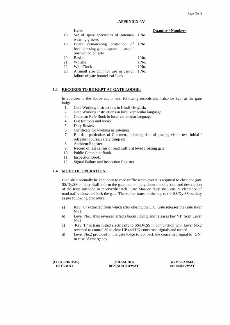
Items Quantity / Numbers18. Set of spare spectacles of gateman
wearing glasses1 No.
19. Board demarcating protection oflevel crossing gate diagram in case ofobstruction on gate
1 No.
20. Basket 1 No.21. Whistle 1 No.22. Wall Clock 1 No.23. A small size chin for use in cse of
failure of gate boom/Leaf Lock1 No.
1.3 RECORDS TO BE KEPT AT GATE LODGE:
In addition to the above equipment, following records shall also be kept at the gatelodge.
1. Gate Working Instructions in Hindi / English.2. Gate Working Instructions in local vernacular language.3. Gateman Rule Book in local vernacular language4. List for tools and books.5. Duty Roster.6. Certificate for working as gateman.7. Bio-data particulars of Gatemen, including date of passing vision test, initial /
refresher course, safety camp etc.8. Accident Register.9. Record of last census of road traffic at level crossing gate.
10. Public Complaint Book.11. Inspection Book.12. Signal Failure and Inspection Register.
1.4 MODE OF OPERATION:
Gate shall normally be kept open to road traffic when ever it is required to close the gateSS/Dy.SS on duty shall inform the gate man on duty about the direction and descriptionof the train intended to receive/dispatch. Gate Man on duty shall ensure clearance ofroad traffic close and lock the gate. There after transmit the key to the SS/Dy.SS on dutyas per following procedure.
a) Key ‘G’ extracted from winch after closing the L.C. Gate releases the Gate leverNo.1.
b) Lever No.1 thus reversed effects boom licking and releases key ‘H’ from LeverNo.1.
c) Key ‘H’ is transmitted electrically to SS/Dy.SS in conjunction with Lever No.2reversed to control 30 to clear UP and DN concerned signals and turned.
d) Lever No.2 provided in the gate lodge to put back the concerned signal to ‘ON’in case of emergency

Page No. 4
(CH.B.SRINIVAS) (E.D.SAHOO) (G.V.S.SARMA)DSTE/WAT DEN(NORTH)/WAT Sr.DOM/G/WAT
APPENDIX-‘A’
1.5 DUTIES OF GATEMAN:
1. ALERTNESS:
The gateman shall be alert and be prepared to take immediate action, shoulddanger be apprehended. Keys of the gate shall be in his personal custody.
2. POSITION DURING PASSAGE OF TRAINS:
During passage of trains, gateman will stand in the manner indicated below:i) Gateman will stand alternatively in front of the gate-lodge facing the
approaching train.
ii) In day time, gateman shall hold red and green flags furled up on separatesticks in right and left hands respectively.
iii) In night time, gateman shall hold lighted hand signal lamp with white lightfacing the track.
iv) He shall keep the whistle slung around his neck from a cord.
3. ROUTING DUTIES OF GATEMAN:
i) Gateman shall ensure that red flag is placed across the track whenever thegate is kept in open condition for passage of road vehicles.
ii) Gateman shall ensure that gate lamps and lamps of all gate signals arelighted and kept burning continuously from sunset to sunrise.
iii) Gateman shall perform his duties strictly according to the duty roster andshall not leave the gate unless reliever arrives and takes charge of it.However, it is necessary to leave the gate in an emergency, he must closeand lock the gates against road traffic, before leaving the gate.
iv) Except where otherwise prescribed under Special Instructions, he shallobserve all passing trains and be prepared to take such action as may benecessary to ensure safety of trains.
v) Gateman shall watch all passing trains and keep sharp look out for anyunusual like hot axle, hanging chains, hanging battery, and vehicle /wagons / train / battery box on fire, shifted load, falling material like brakeblocks, brake beams, safety bracket, vacuum cylinder or any other situationendangering safe running of trains.
vi) Gateman shall also prepared to repeat any signal which guard may give toLoco Pilot on walkie-talkie or in any other way.

Page No. 5
(CH.B.SRINIVAS) (E.D.SAHOO) (G.V.S.SARMA)DSTE/WAT DEN(NORTH)/WAT Sr.DOM/G/WAT
APPENDIX-‘A’
vii) If lifting barriers get damaged or becomes out of order, the gateman shalluse the spare chain with disc and padlocks for securing the gate againstroad traffic.
viii) Gateman shall report to the nearest Station Master, Gangmate orPermanent Way Inspector any defect in his gate or apparatus pertaining toit, as soon as possible.
ix) In the event of gate signal becoming defective the gateman shall maintainthe signal in the ‘ON’ position even by disconnecting the signal or thewire if necessary.
x) At the gate whose signal have become defective, the gateman shall closeand lock the lifting barriers on sighting a train and hand signal or pilot thetrain past the defective signal. In such case he should inform the LocoPilot to report the defect at the next station.
xi) Gateman shall wear badge and prescribed uniform while on duty at levelcrossing gate.
xii) Gateman shall ensure that he is having competency certificate in hispossession while on duty.
xiii) Gateman shall work the gate as per Gate Working Instructions and remainwell conversant with these instructions.
xiv) Gateman shall ensure that equipment supplied at the gate is in good orderand ready for immediate use.
xv) Gateman shall see that the channel for the flange of the wheel is kept clean.
xvi) Gateman shall keep the road surface well watered and rammed in case ofun metalled roads.
xvii) Gateman must be vigilant to see that inconvenience to road users due toclosure of gates should be to the minimum possible extent.
xviii) Gateman on electrified section shall watch that road vehicles / animalspassing from gate are within the height loading gauge provided on eitherside of the level crossing gate.
xix) Gateman shall prevent tress passing by persons or cattle to the maximumextent.
Page No. 6
(CH.B.SRINIVAS) (E.D.SAHOO) (G.V.S.SARMA)DSTE/WAT DEN(NORTH)/WAT Sr.DOM/G/WAT
APPENDIX-‘A’
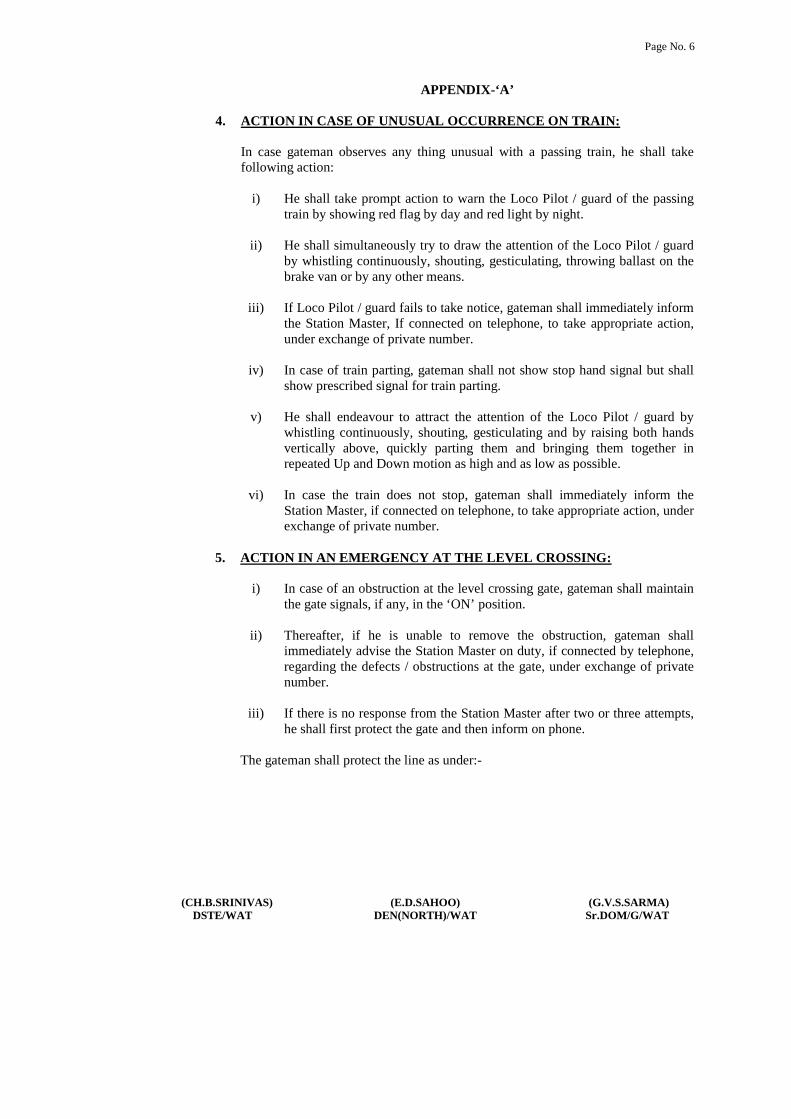
4. ACTION IN CASE OF UNUSUAL OCCURRENCE ON TRAIN:
In case gateman observes any thing unusual with a passing train, he shall takefollowing action:
i) He shall take prompt action to warn the Loco Pilot / guard of the passingtrain by showing red flag by day and red light by night.
ii) He shall simultaneously try to draw the attention of the Loco Pilot / guardby whistling continuously, shouting, gesticulating, throwing ballast on thebrake van or by any other means.
iii) If Loco Pilot / guard fails to take notice, gateman shall immediately informthe Station Master, If connected on telephone, to take appropriate action,under exchange of private number.
iv) In case of train parting, gateman shall not show stop hand signal but shallshow prescribed signal for train parting.
v) He shall endeavour to attract the attention of the Loco Pilot / guard bywhistling continuously, shouting, gesticulating and by raising both handsvertically above, quickly parting them and bringing them together inrepeated Up and Down motion as high and as low as possible.
vi) In case the train does not stop, gateman shall immediately inform theStation Master, if connected on telephone, to take appropriate action, underexchange of private number.
5. ACTION IN AN EMERGENCY AT THE LEVEL CROSSING:
i) In case of an obstruction at the level crossing gate, gateman shall maintainthe gate signals, if any, in the ‘ON’ position.
ii) Thereafter, if he is unable to remove the obstruction, gateman shallimmediately advise the Station Master on duty, if connected by telephone,regarding the defects / obstructions at the gate, under exchange of privatenumber.
iii) If there is no response from the Station Master after two or three attempts,he shall first protect the gate and then inform on phone.
The gateman shall protect the line as under:-
Page No. 7
(CH.B.SRINIVAS) (E.D.SAHOO) (G.V.S.SARMA)DSTE/WAT DEN(NORTH)/WAT Sr.DOM/G/WAT
APPENDIX-‘A’
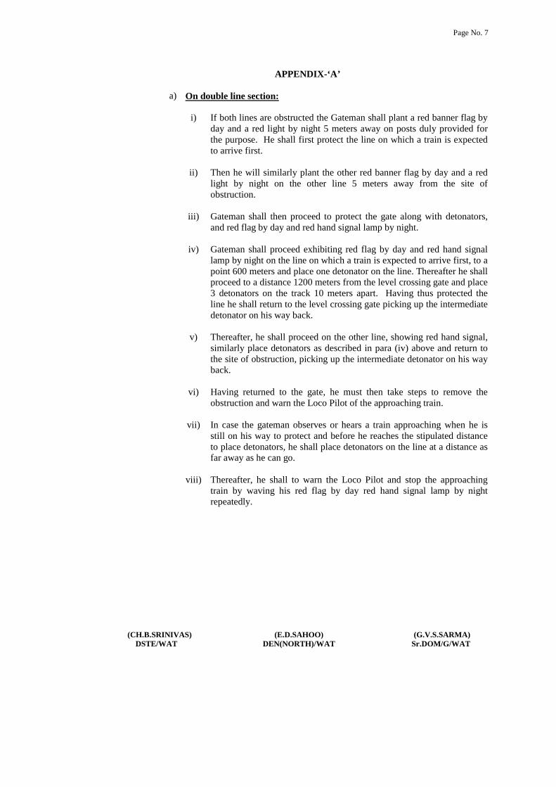
a) On double line section:
i) If both lines are obstructed the Gateman shall plant a red banner flag byday and a red light by night 5 meters away on posts duly provided forthe purpose. He shall first protect the line on which a train is expectedto arrive first.
ii) Then he will similarly plant the other red banner flag by day and a redlight by night on the other line 5 meters away from the site ofobstruction.
iii) Gateman shall then proceed to protect the gate along with detonators,and red flag by day and red hand signal lamp by night.
iv) Gateman shall proceed exhibiting red flag by day and red hand signallamp by night on the line on which a train is expected to arrive first, to apoint 600 meters and place one detonator on the line. Thereafter he shallproceed to a distance 1200 meters from the level crossing gate and place3 detonators on the track 10 meters apart. Having thus protected theline he shall return to the level crossing gate picking up the intermediatedetonator on his way back.
v) Thereafter, he shall proceed on the other line, showing red hand signal,similarly place detonators as described in para (iv) above and return tothe site of obstruction, picking up the intermediate detonator on his wayback.
vi) Having returned to the gate, he must then take steps to remove theobstruction and warn the Loco Pilot of the approaching train.
vii) In case the gateman observes or hears a train approaching when he isstill on his way to protect and before he reaches the stipulated distanceto place detonators, he shall place detonators on the line at a distance asfar away as he can go.
viii) Thereafter, he shall to warn the Loco Pilot and stop the approachingtrain by waving his red flag by day red hand signal lamp by nightrepeatedly.

Page No. 8
(CH.B.SRINIVAS) (E.D.SAHOO) (G.V.S.SARMA)DSTE/WAT DEN(NORTH)/WAT Sr.DOM/G/WAT
APPENDIX-‘A’
b) Other action to be taken by Gateman:
i) At night Gateman shall light two hand signal lamps and take action toexhibit red light and protect the lines as described in sub paras (A) and(B) above.
ii) If the gate is broken by a road vehicle which is fouling the track, or iflifting barriers or any other part of the gate foul the track, or if there isany other obstruction at the gate, the gateman shall take immediateaction.
iii) He shall note down the particulars of the road vehicle, vehicle number,name of the driver, owner and relay these details to the nearest StationMaster or Permanent Way Inspector regarding the particulars andobstructions at the level crossing gate, through messenger or throughmeans available.
1.6 ENGINEERING ITEMS:
Please see para 916, 918, 919 of IRPWM for visibility requirements at level crossings,provision of speed breakers on the approaching roads of level crossings and census oftraffic at level crossings.

Page No. 9
(CH.B.SRINIVAS) (E.D.SAHOO) (G.V.S.SARMA)DSTE/WAT DEN(NORTH)/WAT Sr.DOM/G/WAT
WORKING INSTRUCTIONS FOR TRAFFIC LEVEL CROSSING GATESINTERLOCKED WITH STOP SIGNALS OF THE STATION, PROVIDED WITHTELEPHONE, WITH NORMAL POSITION “OPEN TO ROAD TRAFFIC” at KM 389/7-8in PVP YARD(General Instructions are common for all types of Manual Level Crossing Gates)
1. Mode of Operation:
Gate shall normally be kept open to road traffic when ever it is required to close thegate SS/Dy.SS on duty shall inform the gate man on duty about the direction anddescription of the train intended to receive. Gate Man on duty shall ensure clearance ofroad traffic close and lock the gate. There after transmit the key to the SS/Dy.SS onduty as per following procedure.
a) Key ‘G’ extracted from winch after closing the L.C. Gate releases the Gate leverNo.1.
b) Lever No.1 thus reversed effects boom licking and releases key ‘H’ from LeverNo.1.
c) Key ‘H’ is transmitted electrically to SS/Dy.SS in conjunction with Lever No.2reversed to control 30 to clear UP and DN concerned signals and turned.
d) Lever No.2 provided in the gate lodge to put back the concerned signal to ‘ON’in case of emergency
2. Exchange of Private Numbers:
(i) Before taking off reception / departure signals Station Master shall inform thegateman, the number, description and direction of the train.
(ii) The gateman shall close the gate and transfer the key to the Station Master.
(iii) The reception / departure signals will then be taken ‘OFF’.
(iv) In order to ensure that road traffic is not held up for a long time, the StationMaster must ensure that the train is ready for departure in all respects before headvises the gateman for closing the gate.
(v) If the gate is operated from the cabin itself, Station Master shall ensure that thegate is closed against road traffic, before taking ‘OFF’ reception / departuresignals.
(vi) When a train has to be piloted to and from the station yard or any shuntingmovement is to be done, the staff deputed to pilot the train or to perform theshunting across the gate shall be personally responsible to ensure that the gate isclosed against road traffic before allowing any movement across the gate.

Page No. 10
(CH.B.SRINIVAS) (E.D.SAHOO) (G.V.S.SARMA)DSTE/WAT DEN(NORTH)/WAT Sr.DOM/G/WAT
3. Failure of Telephonic Communication:
When Telephonic Communication fails or it does not get any response from theGateman despite 2 or 3 attempts, the following procedure should be adopted:
(i) Station Master on duty shall send written advice to the gateman through the porterwith full details of number, description and direction of the train.
(ii) Gateman on receipt of such advice shall close the gate and transmit the key to theStation Master which will enable them to take ‘OFF’ reception / departure signals.
(iii) When sufficient time is not available because of greater frequency of train serviceStation Master will issue written authority to the train Loco Pilot to pass the signal at‘ON’ position.
(iv) In addition Station Master shall also issue a caution order advising the Loco Pilot towhistle continuously and approach the gate cautiously.
(v) The train Loco Pilot shall be instructed to pass the gate cautiously, on being handsignalled by the gateman. If hand signal is not seen, Loco Pilot should be prepared tostop short of the gate and ensure that gate is closed following GR 3.73(2)(b).
(vi) In case of an approaching train, the Station Master shall advise the Station Master atthe despatching end, under exchange of private number, that the telephone at the gatehas failed.
(vii) The Station Master at the despatching end shall then issue a caution order to the drivebefore despatching a train in the block section from his end.
(viii) He should also advise S&T staff responsible for maintenance of the telephone torectify the defect at the earliest.
(ix) Normal working will be resumed only after S&T staff rectify the telephone and issuereconnection / fit memo for the same.
4. Failure of Lifting Barriers :
(i) When the gate cannot be closed due to failure of lifting barriers gateman willimmediately inform the Station Master on duty, under exchange of private number,and ensure the lifting barriers do not foul the track.
(ii) He shall immediately fix red banner flag by day and red light by night on the post atthat end first from which the train is approaching and then at the other end.
(iii) Gateman shall secure the gate against road traffic by means of safety chains andpadlocks.

Page No. 11
(CH.B.SRINIVAS) (E.D.SAHOO) (G.V.S.SARMA)DSTE/WAT DEN(NORTH)/WAT Sr.DOM/G/WAT
(iv) After securing the gate against road traffic, gateman shall show green hand signal flagby day and green light by night to the Loco Pilot of the approaching train.
(v) Station Master on duty shall issue a caution order to the Loco Pilot of a departing train.
(vi) He shall also advise the Station Master at the despatching end, under exchange ofprivate number, to similarly issue a caution order to the Loco Pilot before despatchinga train the block section from his end.
(vii) Station Master will advise maintenance staff responsible for maintenance of liftingbarriers / leaf gates to repair the defect at the earliest.
(viii) Normal working will resumed only after maintenance staff repair the barrier and issuereconnection / fit memo for the same.
Note:(a) In case of failure of lifting barriers worked from the cabin, Station Master will send
station porter to secure the gate against road traffic by safety chains and padlocks.
(b) Authority to pass signals at ‘ON’ position as per rules shall also be issued to the LocoPilot of both departing and arriving trains.
5. Failure of the Gate Key with the gate in closed position when Gate Key cannot beextracted for opening the gate:
(i) If the gate key cannot be extracted from the winch, the key transmitter, then gatemanmust immediately inform the Station Master on duty on telephone, under exchange ofprivate number.
(ii) If Emergency Key is available at he gate lodge / cabin, Gateman will take it out fromthe sealed box by breaking the seal and open the gate for road traffic.
(iii) The record of the date and time of breaking the sealed cover of Emergency Key Boxshall be recorded and signed with reasons.
(iv) Thereafter, the gate must be treated as non-interlocked and procedure for reception /despatch of trains as prescribed for non-interlocked gates, should be adopted.
(v) Station Master on duty shall issue a caution order to the Loco Pilot of a departing train.
(vi) He shall also advise the Station Master at the dispatching end, under exchange ofprivate number, to similarly issue a caution order to the Loco Pilot before dispatchinga train in the block section from his end.
(vii) Station Master will advise S&T staff responsible for maintenance of winch / keytransmitter to rectify the defect at the earliest.
Page No. 12
(CH.B.SRINIVAS) (E.D.SAHOO) (G.V.S.SARMA)DSTE/WAT DEN(NORTH)/WAT Sr.DOM/G/WAT
(viii) Normal working will resumed only after S&T staff repair the winch / key transmitterand issue reconnection / fit memo for the same.
(ix) After rectification, the Emergency Key shall be replaced in the Emergency Key Boxand resealed by the S&T maintainer.
6. Failure of the Gate Key, with the gate in open condition:
(i) If the gate key cannot be extracted from the winch, gate lever or key transmitter thengateman must immediately inform the Station Master on duty on telephone underexchange of private number.
(ii) Thereafter, the gate must be treated as non-interlocked and procedure for reception /dispatch of trains as prescribed for non-interlocked gates should be adopted.
(iii) Gateman shall secure the gate against road traffic by means of chains and padlocks andpass the trains on hand signals.
(iv) Station Master on duty shall issue caution order to the Loco Pilot of a departing train.
(v) He shall also advise the Station Master at the dispatching end under exchange ofprivate number to similarly issue a caution order to the Loco Pilot before dispatching atrain in the block section from his end.
(vi) Station Master will advise S&T staff responsibility for maintenance of winch/ keytransmitter to rectify the defect at the earliest.
(vii) Normal working will resumed only after S&T staff repair the winch / key transmitterand issue reconnection / fit memo for the same.
(viii) After rectification, the Emergency Key shall be replaced in the Emergency Key Boxand released by the S&T maintainer.
7. Obstruction at the Gate:
(i) If the gate is broken by a road vehicle which is fouling the track, or if lifting barriersor any other part of the gate foul the track, or if there is any other obstruction at thegate, the gateman shall immediately fix red banner flag by day and red lamp by nighton posts provided at both ends of the gate, for this purpose.
(ii) Immediately after this, the gateman shall advise the Station Master on duty, regardingthe defects / obstruction at the gate, under exchange of private number.
(iii) Station Master on duty shall be advised to put the reception / departure signals back to‘ON’ position, if taken ‘OFF’ for a train.
(iv) If there is no response from the Station Master after two or three attempts, he shall firstprotect the gate and then inform on phone.

Page No. 13
(CH.B.SRINIVAS) (E.D.SAHOO) (G.V.S.SARMA)DSTE/WAT DEN(NORTH)/WAT Sr.DOM/G/WAT
(v) Gateman shall then rush with detonators, and red flag by day and red hand signal lampby night in the direction of the approaching train and protect the gate as stipulated inGeneral Instruction for duties of gateman under item no.1.5(5).
(vi) There he shall protect the gate from the other direction also.
(vii) He shall note down the particulars of the road vehicle, name of the driver, owner andrelay these details to the Station Master who shall not start the train unless he has beenassured by the gateman that the road vehicle or the lifting barriers are not fouling thetrack.
(viii) The Station Master shall also inform the Station Master at the dispatching end, underexchange of private number, asking him not to dispatch any train in the block sectionfrom his end, until the track has been cleared of all obstructions.
(ix) After the track has been cleared of all obstructions the gateman shall inform theStation Master accordingly, under exchange of private number.
(x) Station Master shall then issue a caution order to Loco Pilot of all train to proceedcautiously, and pass the reception / departure signal at ‘ON’ position on green handsignal of the gateman, of the gate is broken, but is clear of any obstruction.
(xi) Gateman shall secure the gate against road traffic by means of safety chains andpadlocks and there after exhibit green hand signal, if the gate is not obstructed.
(xii) Station Master shall advise maintenance staff responsible for maintaining the liftingbarriers to repair same at the earliest.
(xiii) Normal working will be resumed only after maintenance staff rectify the defectivelifting barriers and issue reconnection / fit memo for the same.
8. Obstruction on the Track near Level Crossing:
If there is a rail fracture or obstruction on the track due to failing of a tree, fouling byroad vehicle or derailment which is visible to the gateman, the gateman and StationMaster will adopt the procedure given under item No.7 above. If the obstruction foulsthe Level Crossing Gate, gateman must keep the gates closed against road traffic tillthe track is cleared of the obstruction.

Page No. 14
(CH.B.SRINIVAS) (E.D.SAHOO) (G.V.S.SARMA)DSTE/WAT DEN(NORTH)/WAT Sr.DOM/G/WAT
APPENDIX-‘A’
APPENDIX ‘A’ TO STATION WORKING RULES OF PARVATIPURAMSTATION LEVEL CROSSING GATES
1. GENERAL:
1.1 DESCRIPTION OF THE LEVEL CROSSING GATE:Following details shall be maintained at all manned level crossing gates:
1 No. of Level Crossing Gate : RV-281
2 Engineering or Traffic gate Engineering Gate –‘B’ Class
3 Under control of station master orpermanent way inspector.
SSE(P)/PVP
4 Location at Km. KM. 387/7-8
5 At station -
6 In between station PVP-GMDA
7 BG/MG/NG : BG
8 Single line/double line/multiple line : Double line
9 Normal position : Open to Road Traffic
10 Interlocked/ Non-Interlocked : Interlocked
11 Means of Interlocking : Electrical lever frame and ElectricalKey transmission to control no 29
12 Provision of gate single at Km. : i) Up Line :386/15ii) DN Line : 388/6
13 Signaling arrangement : MACL
14 Means of communication Telephone. : Telephone Connected with PVPStation
15 Width of the level crossing gate : 10 M
16 Type of road : SH
17 Name of road : Palakonda Raod
18 Metalled /Non-Metalled : Metalled
19 Approach road : Level
20 Width of the road : 7 M
21 Angle of road crossing (in case of theSKEW gates)
: Square
22 Road gradients (if any) : [a]North/East Side: Level: [b]South/West Side: Level
23 Road alignment (straight/Curve) : [a] North/East Side : Straight[b] South/East Side : Straight

Page No. 15
(CH.B.SRINIVAS) (E.D.SAHOO) (G.V.S.SARMA)DSTE/WAT DEN(NORTH)/WAT Sr.DOM/G/WAT
APPENDIX-‘A’
24 Provision of height gauges : Nil
25 Type of barriers : Coupled Lifting Barriers
26 Length of check rails : 12.5 M
27 Road surface in between levelcrossing gates.
: Level
28 Length of rumble strip/ speedbreakers.
: 45 / 26 M
29 Road signs : Provided
30 Speed breakers indication board : Provided
31 TVU: : 162196
32 Census next due on : 2012
33 Demarcation for placement ofdetonators.
: Provided
34 No. of gateman working : 3
35 Nearest Railway Medical Assistance : Sr.DMO/RGDA
36 Nearest Private Medical Assistanceavailable (if any)
: Parvatipuram
37 List of equipment available (Yes/No) : Yes
1.2 EQUIPMENT:Items Quantity / Numbers
1. Hand Signal Lamp Tri Colour 5 Nos.2. Hand Signal Flag Green 1 No with mounted stick3. Hand Signal Flag Red 6 Nos.4. Banner Flag Red 5 Nos.5. Posts for exhibiting red banner flag 4 Nos.6. Spare chains with padlocks 2 with stop marker7. Detonators 10 in each case8. Gate lamps 2 Nos.9. Tommy Bar 1 No.
10. Mortar Pan 1 No.11. Spade / Fowrah 1 No.12. Rammer 1 No (In case of asphalted road this may
not be provided )13. Pick Axe 1 No (In case of asphalted road this may
not be provided )14. Tin case for flags 1 No.15. Can for oil 1 No.16. Water port / Bucket 1 No.17. Canister for Muster Roll 1 No.

Page No. 16
(CH.B.SRINIVAS) (E.D.SAHOO) (G.V.S.SARMA)DSTE/WAT DEN(NORTH)/WAT Sr.DOM/G/WAT
APPENDIX-‘A’
Items Quantity / Numbers18. Set of spare spectacles of gateman
wearing glasses1 No.
19. Board demarcating protection oflevel crossing gate diagram in case ofobstruction on gate
1 No.
20. Basket 1 No.21. Whistle 1 No.22. Wall Clock 1 No.23. A small size chin for use in cse of
failure of gate boom/Leaf Lock1 No.
1.3 RECORDS TO BE KEPT AT GATE LODGE:
In addition to the above equipment, following records shall also be kept at the gatelodge.
1. Gate Working Instructions in Hindi / English.2. Gate Working Instructions in local vernacular language.3. Gateman Rule Book in local vernacular language4. List for tools and books.5. Duty Roster.6. Certificate for working as gateman.7. Bio-data particulars of Gatemen, including date of passing vision test, initial /
refresher course, safety camp etc.8. Accident Register.9. Record of last census of road traffic at level crossing gate.
10. Public Complaint Book.11. Inspection Book.12. Signal Failure and Inspection Register.
1.4 MODE OF OPERATION:
Gate shall normally kept open to the road traffic when ever it is required to close thegate SM on duty shall inform the gate man on duty about the direction and descriptionof the train intended to receive or despatch. Gate man on duty shall ensure clearance ofroad traffic close and lock the gate. There after he will perform the following procedureto take off the Gate home signals as the case may be.Key ‘E’ extracted from the winch after closing level crossing gate releases gate leverNo.2 GF.Lever No.2 thus reversed effects boom locking and releases lever No.3 to clear UP gateHome No.3 and Lever No.4 to clear DN Home signal No.4 and also releases Key‘F’.Key ‘F’ is transmitted Electrically to SS/Dy.SS to release control 29 to clear DNAdv. Starter No.12.

Page No. 17
(CH.B.SRINIVAS) (E.D.SAHOO) (G.V.S.SARMA)DSTE/WAT DEN(NORTH)/WAT Sr.DOM/G/WAT
APPENDIX-‘A’
1.5 DUTIES OF GATEMAN:
1. ALERTNESS:
The gateman shall be alert and be prepared to take immediate action, shoulddanger be apprehended. Keys of the gate shall be in his personal custody.
2. POSITION DURING PASSAGE OF TRAINS:
During passage of trains, gateman will stand in the manner indicated below:i) Gateman will stand alternatively in front of the gate-lodge facing the
approaching train.
ii) In day time, gateman shall hold red and green flags furled up on separatesticks in right and left hands respectively.
iii) In night time, gateman shall hold lighted hand signal lamp with white lightfacing the track.
iv) He shall keep the whistle slung around his neck from a cord.
3. ROUTING DUTIES OF GATEMAN:
i) Gateman shall ensure that red flag is placed across the track whenever thegate is kept in open condition for passage of road vehicles.
ii) Gateman shall ensure that gate lamps and lamps of all gate signals arelighted and kept burning continuously from sunset to sunrise.
iii) Gateman shall perform his duties strictly according to the duty roster andshall not leave the gate unless reliever arrives and takes charge of it.However, it is necessary to leave the gate in an emergency, he must closeand lock the gates against road traffic, before leaving the gate.
iv) Except where otherwise prescribed under Special Instructions, he shallobserve all passing trains and be prepared to take such action as may benecessary to ensure safety of trains.
v) Gateman shall watch all passing trains and keep sharp look out for anyunusual like hot axle, hanging chains, hanging battery, and vehicle /wagons / train / battery box on fire, shifted load, falling material like brakeblocks, brake beams, safety bracket, vacuum cylinder or any other situationendangering safe running of trains.
vi) Gateman shall also prepared to repeat any signal which guard may give toLoco Pilot on walkie-talkie or in any other way.
Page No. 18
(CH.B.SRINIVAS) (E.D.SAHOO) (G.V.S.SARMA)DSTE/WAT DEN(NORTH)/WAT Sr.DOM/G/WAT
APPENDIX-‘A’
vii) If lifting barriers get damaged or becomes out of order, the gateman shalluse the spare chain with disc and padlocks for securing the gate againstroad traffic.
viii) Gateman shall report to the nearest Station Master, Gangmate orPermanent Way Inspector any defect in his gate or apparatus pertaining toit, as soon as possible.
ix) In the event of gate signal becoming defective the gateman shall maintainthe signal in the ‘ON’ position even by disconnecting the signal or thewire if necessary.
x) At the gate whose signal have become defective, the gateman shall closeand lock the lifting barriers on sighting a train and hand signal or pilot thetrain past the defective signal. In such case he should inform the LocoPilot to report the defect at the next station.
xi) Gateman shall wear badge and prescribed uniform while on duty at levelcrossing gate.
xii) Gateman shall ensure that he is having competency certificate in hispossession while on duty.
xiii) Gateman shall work the gate as per Gate Working Instructions and remainwell conversant with these instructions.
xiv) Gateman shall ensure that equipment supplied at the gate is in good orderand ready for immediate use.
xv) Gateman shall see that the channel for the flange of the wheel is kept clean.
xvi) Gateman shall keep the road surface well watered and rammed in case ofun metalled roads.
xvii) Gateman must be vigilant to see that inconvenience to road users due toclosure of gates should be to the minimum possible extent.
xviii) Gateman on electrified section shall watch that road vehicles / animalspassing from gate are within the height loading gauge provided on eitherside of the level crossing gate.
xix) Gateman shall prevent tress passing by persons or cattle to the maximumextent.

Page No. 19
(CH.B.SRINIVAS) (E.D.SAHOO) (G.V.S.SARMA)DSTE/WAT DEN(NORTH)/WAT Sr.DOM/G/WAT
APPENDIX-‘A’
4. ACTION IN CASE OF UNUSUAL OCCURRENCE ON TRAIN:
In case gateman observes any thing unusual with a passing train, he shall takefollowing action:
i) He shall take prompt action to warn the Loco Pilot / guard of the passingtrain by showing red flag by day and red light by night.
ii) He shall simultaneously try to draw the attention of the Loco Pilot / guardby whistling continuously, shouting, gesticulating, throwing ballast on thebrake van or by any other means.
iii) If Loco Pilot / guard fails to take notice, gateman shall immediately informthe Station Master, If connected on telephone, to take appropriate action,under exchange of private number.
iv) In case of train parting, gateman shall not show stop hand signal but shallshow prescribed signal for train parting.
v) He shall endeavour to attract the attention of the Loco Pilot / guard bywhistling continuously, shouting, gesticulating and by raising both handsvertically above, quickly parting them and bringing them together inrepeated Up and Down motion as high and as low as possible.
vi) In case the train does not stop, gateman shall immediately inform theStation Master, if connected on telephone, to take appropriate action, underexchange of private number.
5. ACTION IN AN EMERGENCY AT THE LEVEL CROSSING:
i) In case of an obstruction at the level crossing gate, gateman shall maintainthe gate signals, if any, in the ‘ON’ position.
ii) Thereafter, if he is unable to remove the obstruction, gateman shallimmediately advise the Station Master on duty, if connected by telephone,regarding the defects / obstructions at the gate, under exchange of privatenumber.
iii) If there is no response from the Station Master after two or three attempts,he shall first protect the gate and then inform on phone.
The gateman shall protect the line as under:-

Page No. 20
(CH.B.SRINIVAS) (E.D.SAHOO) (G.V.S.SARMA)DSTE/WAT DEN(NORTH)/WAT Sr.DOM/G/WAT
APPENDIX-‘A’
a) On double line section:
i) If both lines are obstructed the Gateman shall plant a red banner flag byday and a red light by night 5 meters away on posts duly provided forthe purpose. He shall first protect the line on which a train is expectedto arrive first.
ii) Then he will similarly plant the other red banner flag by day and a redlight by night on the other line 5 meters away from the site ofobstruction.
iii) Gateman shall then proceed to protect the gate along with detonators,and red flag by day and red hand signal lamp by night.
iv) Gateman shall proceed exhibiting red flag by day and red hand signallamp by night on the line on which a train is expected to arrive first, to apoint 600 meters and place one detonator on the line. Thereafter he shallproceed to a distance 1200 meters from the level crossing gate and place3 detonators on the track 10 meters apart. Having thus protected theline he shall return to the level crossing gate picking up the intermediatedetonator on his way back.
v) Thereafter, he shall proceed on the other line, showing red hand signal,similarly place detonators as described in para (iv) above and return tothe site of obstruction, picking up the intermediate detonator on his wayback.
vi) Having returned to the gate, he must then take steps to remove theobstruction and warn the Loco Pilot of the approaching train.
vii) In case the gateman observes or hears a train approaching when he isstill on his way to protect and before he reaches the stipulated distanceto place detonators, he shall place detonators on the line at a distance asfar away as he can go.
viii) Thereafter, he shall to warn the Loco Pilot and stop the approachingtrain by waving his red flag by day red hand signal lamp by nightrepeatedly.

Page No. 21
(CH.B.SRINIVAS) (E.D.SAHOO) (G.V.S.SARMA)DSTE/WAT DEN(NORTH)/WAT Sr.DOM/G/WAT
APPENDIX-‘A’
b) Other action to be taken by Gateman:
i) At night Gateman shall light two hand signal lamps and take action toexhibit red light and protect the lines as described in sub paras (A) and(B) above.
ii) If the gate is broken by a road vehicle which is fouling the track, or iflifting barriers or any other part of the gate foul the track, or if there isany other obstruction at the gate, the gateman shall take immediateaction.
iii) He shall note down the particulars of the road vehicle, vehicle number,name of the driver, owner and relay these details to the nearest StationMaster or Permanent Way Inspector regarding the particulars andobstructions at the level crossing gate, through messenger or throughmeans available.
1.6 ENGINEERING ITEMS:
Please see para 916, 918, 919 of IRPWM for visibility requirements at level crossings,provision of speed breakers on the approaching roads of level crossings and census oftraffic at level crossings.
Page No. 22
(CH.B.SRINIVAS) (E.D.SAHOO) (G.V.S.SARMA)DSTE/WAT DEN(NORTH)/WAT Sr.DOM/G/WAT
ANNEXURE – I
WORKING INSTRUCTIONS FOR ENGINEERING LEVEL CROSSING GATESINTERLOCKED WITH GATE SIGNALS, PROVIDED WITH TELEPHONE WITHNORMAL POSITION “OPEN TO ROAD TRAFFIC” FOR L.C.GATE AT KM 387/7-8BETWEEN PVP-GMDA(General Instructions are common for all types of Manned Level Crossing Gates)
1. Mode of Operation:
Gate shall normally kept open to the road traffic when ever it is required to close thegate SM on duty shall inform the gate man on duty about the direction and descriptionof the train intended to receive or despatch. Gate man on duty shall ensure clearanceof road traffic close and lock the gate. There after he will perform the followingprocedure to take off the Gate home signals as the case may be.Key ‘E’ extracted from the winch after closing level crossing gate releases gate leverNo.2 GF.Lever No.2 thus reversed effects boom locking and releases lever No.3 to clear UPgate Home No.3 and Lever No.4 to clear DN Home signal No.4 and also releases Key‘F’.Key ‘F’ is transmitted Electrically to SS/Dy.SS to release control 29 to clear DNAdv. Starter No.12.
2. Exchange of Private Numbers:
i) Immediately after departure of the train, Station Master shall advise thegateman through telephone connected at his end, the number, description,direction and expected time of passage of the train at the gate.
ii) If the telephone is connected to the station at the receiving end, this advice shallbe given by the Station Master to the gateman as soon as he receives trainentering section advice from the dispatching station.
iii) If the actual running time of the train from either end of the section is less than10 minutes, Station Master will convey this advice to the gateman beforeobtaining / granting line clear.
iv) It should be the duty of the gateman to ensure that the gate is closed in time, sothat there is no detention to the train or excessive detention to road traffic.
3. Failure of Telephonic Comminication:
When Telephonic Communication fails or it does not get any response from theGateman despite 2 or 3 attempts, the following procedure should be adopted:
i) If the telephone falls at the gate connected with the station at the despatchingend, Station Master shall issue a caution order to the Loco Pilot of the departingtrain.

Page No. 23
(CH.B.SRINIVAS) (E.D.SAHOO) (G.V.S.SARMA)DSTE/WAT DEN(NORTH)/WAT Sr.DOM/G/WAT
ii) Station Master shall advise the Loco Pilot to whistle continuously and proceedcautiously while approaching the gate.
iii) In case the gate signal is ‘ON’ he should stop short of the gate signal and followthe procedure laid down under GR 3.73.
iv) In case of an approaching train, the Station Master shall advise the StationMaster at the dispatching end, under exchange of private number, that thetelephone at the gate has failed.
v) The Station Master at the dispatching end shall then issue a caution order to theLoco Pilot before dispatching a train in the block section from his end.
vi) Station Master will also advise the gateman through Gangman / Patrolman /Loco Pilot of the first train that the telephone has become defective.
vii) Station Master should also advise S&T staff responsible for maintenance of thetelephone to rectify the same at the earliest.
viii) Normal working will be resumed only after S&T staff rectify the telephone andissue reconnection / fit memo for the same.
4. Failure of Lifting Barriers
i) When the gate cannot be closed due to failure of lifting barriers, the gatemanshall immediately inform the Station Master on duty under exchange of privatenumber, and ensure that lifting of barriers or leaf gates do not foul the track.
ii) He shall immediately fix red banner flag by day and red light by night on thepost at that end first from which the train is approaching and then at the otherend.
iii) Gateman shall secure that gate against road traffic by means of safety chainsand padlocks.
iv) After securing the gate against road traffic, gateman shall show green handsignal flag by day and green light to the Loco Pilot of the approaching train.
v) Station Master on duty shall issue caution order to the Loco Pilot of a departingtrain.
vi) He shall also advise the Station Master at the dispatching end, under exchangeof private number; to similarly issue a caution order to the Loco Pilot beforedespatching a train in the block section.
vii) Station Master shall advise maintenance staff responsible for maintaining thelifting barrier to rectify the same at the earliest.

Page No. 24
(CH.B.SRINIVAS) (E.D.SAHOO) (G.V.S.SARMA)DSTE/WAT DEN(NORTH)/WAT Sr.DOM/G/WAT
viii) Normal working will be resumed only after maintenance staff repair the liftingbarrier and issue reconnection / fit memo for the same.
5. Failure of Gate Key with the gate in closed position, when Gate Key cannot beextracted for opening the gate:
i) If the gate key cannot be extracted from the winch, gate signal lever or keytransmitter then gateman must immediately inform the Station on duty ontelephone, under exchange of private number.
ii) If Emergency Key is available at the gate lodge / cabin, Gateman will take it outfrom the sealed box by breaking the seal and open the gate for road traffic.
iii) The record of the date and time of breaking the sealed cover of Emergency keyBox shall be recorded and signed with reasons.
iv) Thereafter, the gate must be treated as non-interlocked and procedure forreception / despatch of trains as prescribed for non-interlocked gates, should beadopted.
v) Station Master on duty shall issue caution order to the Loco Pilot of a departingtrain.
vi) He shall also advise the Station Master at the dispatching end, under exchangeof private number, to similarly issue a caution order to the Loco Pilot beforedespatching a train in the block section from his end.
vii) Station Master shall advise S&T staff responsible for maintaining the keytransmitter to repair the same at the earliest.
viii) Normal working will be resumed only after S&T staff repair the key transmitterand issue reconnection / fit memo for the same.
ix) After rectification, the Emergency key shall be replaced in the Emergency KeyBox and resealed by the S&T maintainer.
6. Failure of the Gate Key with the gate in open condition:
i) If the gate key cannot be extracted from the winch, gate signal lever or keytransmitter then gateman must immediately inform the Station Master on dutyon telephone, under exchange of private number.
ii) Thereafter, the gate must be treated as non-interlocked and procedure forreception / despatch of trains as prescribed for non-interlocked gates, should beadopted.
iii) The gateman shall secure the gate against road traffic by means of chains andpadlocks and pass trains on hand signals.

Page No. 25
(CH.B.SRINIVAS) (E.D.SAHOO) (G.V.S.SARMA)DSTE/WAT DEN(NORTH)/WAT Sr.DOM/G/WAT
iv) Station Master on duty shall issue a caution order to the Loco Pilot of adeparting train.
v) He shall also advise the Station Master at the despatching end, under exchangeof private number, to similarly issue a caution order to the Loco Pilot beforedispatching a train in the block section from his end.
vi) Station Master shall advise S&T staff responsible for maintaining the keytransmitter to repair the same at the earliest.
vii) Normal working will be resumed only after S&T staff repair the key transmitterand issue reconnection / fit memo for the same.
viii) After rectification, the Emergency key shall be replaced in the Emergency KeyBox and resealed by the S&T maintainer.
7. Defective Gate Signals:
i) The gateman shall treat the gate as defective and must not lower them underfollowing circumstances:
a) If gate signals can be taken ‘OFF’ without closing the gate, or
b) The key can be extracted from the operation winch when the gate is inopen condition, or
c) The key can be extracted from the gate is in open condition
ii) If the Gate or the Gate Signal or Warner / Distant Signal becomes defective in‘OFF’ position, the gateman will make all efforts to put it at ‘ON’ position evenby cutting signal wires, if necessary.
iii) The gateman will immediately advise the Station Master on duty, underexchange of private number, regarding defective gate signals.
iv) Thereafter, the gate must be treated as non-interlocked and procedure forreception / dispatch as prescribed for non-interlocked gates should be adopted.
v) He shall show green hand signal flag by day and green light by night to thepassing train after closing the gate.
vi) Station Master on duty will issue a caution order to the Loco Pilot of adeparting train.
vii) He shall also advise the Station Master at the dispatching end, under exchangeof private number, to similarly issue a caution order to the Loco Pilot beforedespatching a train in the block section from his end.

Page No. 26
(CH.B.SRINIVAS) (E.D.SAHOO) (G.V.S.SARMA)DSTE/WAT DEN(NORTH)/WAT Sr.DOM/G/WAT
viii) Station Master shall advise S&T staff responsible for maintaining the gatesignal to repair the same at the earliest.
ix) Normal working will be resumed only after S&T staff rectify the defective gatesignal and issue reconnection / fit memo for the same,
8. Obstruction at the Gate:
i) If the gate is broken by road vehicle which is fouling the track, or if liftingbarriers or any other part of the gate foul the track, or if there is any otherobstruction at the gate, the gateman shall immediately put back gate signals to‘ON’ position.
ii) He shall fix red banner flag by day and red lamp by night on posts provided atboth ends of the gate for this purpose.
iii) Immediately after this, the gateman shall advise the Station Masteron dutyregarding the defects / obstructions at the gate, under exchange of privatenumber.
iv) If there is no response from the Station Master after two or three attempts, heshall first protect the gate and then inform on phone.
v) Gateman shall then rush with detonators, and red flag by day and red handsignal lamp by night in the direction of the approaching train and protect thegate as stipulated in General Instruction for duties of gateman under item no.1.5(5).
vi) Thereafter he shall protect the gate from the other direction also.
vii) He shall note down the particulars of the road vehicle, name of the driver,owner and relay these details to the Station Master who shall not start the trainunless he has been assured by the gateman that the road vehicle or the liftingbarriers / leaf gates are not fouling the track.
viii) The Station Master shall also inform the Station Master at the despatching end,under exchange of private number, asking him not to despatch any train in theblock section from his end, until the track has been cleared of all obstruction.
ix) After the track has been cleared of all obstructions the gateman shall inform theStation Master accordingly, under exchange of private number.
x) Station Master shall then issue a caution order to Loco Pilot of all trains toproceed cautiously, and pass the gate signal at ‘ON’ position on green handsignal of the gateman, of the gate is broken, but is clear of any obstruction.
xi) Gateman shall secure the gate against road traffic by means of safety chains andpadlocks, and there after exhibit green hand signal, if the gate is not obstructed.
Page No. 27
(CH.B.SRINIVAS) (E.D.SAHOO) (G.V.S.SARMA)DSTE/WAT DEN(NORTH)/WAT Sr.DOM/G/WAT
xii) Station Master shall advise maintenance staff responsible for maintaining thelifting barriers to repair the same at the earliest.
xiii) Normal working will be resumed only after maintenance staff rectify thedefective lifting barriers and issue reconnection / fit memo for the same.
9. Obstruction on the Track near Level Crossing Gate:
If there is a rail fracture or obstruction on the track due to falling of a tree, fouling byroad vehicle or derailment which is visible to the gateman, the gateman and StationMaster will adopt the procedure given under item No.8 above. If the obstruction foulsthe Level Crossing Gate, gateman must keep the gates closed against road traffic tillthe track is cleared of the obstruction.

Page No. 28
(CH.B.SRINIVAS) (E.D.SAHOO) (G.V.S.SARMA)DSTE/WAT DEN(NORTH)/WAT Sr.DOM/G/WAT
APPENDIX-‘A’
APPENDIX ‘A’ TO STATION WORKING RULES OF PARVATIPURAMSTATION LEVEL CROSSING GATES
1. GENERAL:
1.1 DESCRIPTION OF THE LEVEL CROSSING GATE:Following details shall be maintained at all manned level crossing gates:
1 No. of Level Crossing Gate : RV-278
2 Engineering or Traffic gate Engineering Gate –‘Spl’ Class
3 Under control of station master orpermanent way inspector.
SSE(P)/PVP
4 Location at Km. KM. 382/12-13
5 At station -
6 In between station PVP-GMDA
7 BG/MG/NG : BG
8 Single line/double line/multiple line : Double line
9 Normal position : Open to Road Traffic
10 Interlocked/ Non-Interlocked : Interlocked
11 Means of Interlocking : Ground Lever Frame
12 Provision of gate single at Km. : i) Up Line :382.550ii) DN Line : 382.920
13 Signaling arrangement : MACL
14 Means of communication Telephone. : Telephone Connected with PVPStation
15 Width of the level crossing gate : 10 M
16 Type of road : Others
17 Name of road : RGDA Road
18 Metalled /Non-Metalled : Metalled
19 Approach road : Level
20 Width of the road : 10 M
21 Angle of road crossing (in case of theSKEW gates)
: Square
22 Road gradients (if any) : [a]North/East Side: Level: [b]South/West Side: Level
23 Road alignment (straight/Curve) : [a] North/East Side : Straight[b] South/East Side : Straight
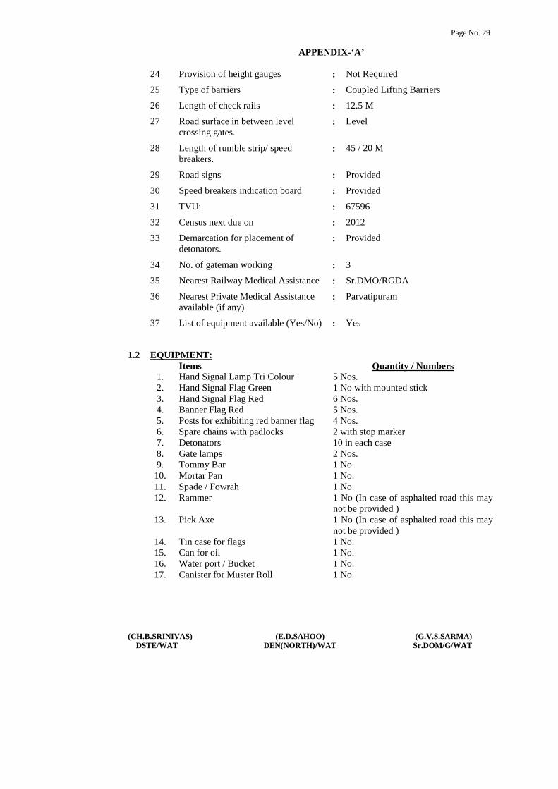
Page No. 29
(CH.B.SRINIVAS) (E.D.SAHOO) (G.V.S.SARMA)DSTE/WAT DEN(NORTH)/WAT Sr.DOM/G/WAT
APPENDIX-‘A’
24 Provision of height gauges : Not Required
25 Type of barriers : Coupled Lifting Barriers
26 Length of check rails : 12.5 M
27 Road surface in between levelcrossing gates.
: Level
28 Length of rumble strip/ speedbreakers.
: 45 / 20 M
29 Road signs : Provided
30 Speed breakers indication board : Provided
31 TVU: : 67596
32 Census next due on : 2012
33 Demarcation for placement ofdetonators.
: Provided
34 No. of gateman working : 3
35 Nearest Railway Medical Assistance : Sr.DMO/RGDA
36 Nearest Private Medical Assistanceavailable (if any)
: Parvatipuram
37 List of equipment available (Yes/No) : Yes
1.2 EQUIPMENT:Items Quantity / Numbers
1. Hand Signal Lamp Tri Colour 5 Nos.2. Hand Signal Flag Green 1 No with mounted stick3. Hand Signal Flag Red 6 Nos.4. Banner Flag Red 5 Nos.5. Posts for exhibiting red banner flag 4 Nos.6. Spare chains with padlocks 2 with stop marker7. Detonators 10 in each case8. Gate lamps 2 Nos.9. Tommy Bar 1 No.
10. Mortar Pan 1 No.11. Spade / Fowrah 1 No.12. Rammer 1 No (In case of asphalted road this may
not be provided )13. Pick Axe 1 No (In case of asphalted road this may
not be provided )14. Tin case for flags 1 No.15. Can for oil 1 No.16. Water port / Bucket 1 No.17. Canister for Muster Roll 1 No.

Page No. 30
(CH.B.SRINIVAS) (E.D.SAHOO) (G.V.S.SARMA)DSTE/WAT DEN(NORTH)/WAT Sr.DOM/G/WAT
APPENDIX-‘A’
Items Quantity / Numbers18. Set of spare spectacles of gateman
wearing glasses1 No.
19. Board demarcating protection oflevel crossing gate diagram in case ofobstruction on gate
1 No.
20. Basket 1 No.21. Whistle 1 No.22. Wall Clock 1 No.23. A small size chin for use in cse of
failure of gate boom/Leaf Lock1 No.
1.3 RECORDS TO BE KEPT AT GATE LODGE:
In addition to the above equipment, following records shall also be kept at the gatelodge.
1. Gate Working Instructions in Hindi / English.2. Gate Working Instructions in local vernacular language.3. Gateman Rule Book in local vernacular language4. List for tools and books.5. Duty Roster.6. Certificate for working as gateman.7. Bio-data particulars of Gatemen, including date of passing vision test, initial /
refresher course, safety camp etc.8. Accident Register.9. Record of last census of road traffic at level crossing gate.
10. Public Complaint Book.11. Inspection Book.12. Signal Failure and Inspection Register.
1.4 MODE OF OPERATION:
Gate shall normally kept open to the road traffic when ever it is required to close thegate SM on duty shall inform the gate man on duty about the direction and descriptionof the train intended to receive or despatch. Gate man on duty shall ensure clearance ofroad traffic close and lock the gate. There after he will perform the following procedureto take off the Gate home signals as the case may be.
i) Key ‘M’ is obtained form winch after closing the level crossing releases 1GF.ii) Lever No 1 GF reversed effects the level crossing boom lock releases key ‘N’iii) Key ‘IN’ contact of RKT along with reversal of switches 3GS clear concerned
UP gate stop signal (3GS) and DN gate stop signal (4GS) respectively.iv) In case of emergency signals can be put back to ‘ON’ by normalizing the signal
switches.

Page No. 31
(CH.B.SRINIVAS) (E.D.SAHOO) (G.V.S.SARMA)DSTE/WAT DEN(NORTH)/WAT Sr.DOM/G/WAT
APPENDIX-‘A’
1.5 DUTIES OF GATEMAN:
1. ALERTNESS:
The gateman shall be alert and be prepared to take immediate action, shoulddanger be apprehended. Keys of the gate shall be in his personal custody.
2. POSITION DURING PASSAGE OF TRAINS:
During passage of trains, gateman will stand in the manner indicated below:i) Gateman will stand alternatively in front of the gate-lodge facing the
approaching train.
ii) In day time, gateman shall hold red and green flags furled up on separatesticks in right and left hands respectively.
iii) In night time, gateman shall hold lighted hand signal lamp with white lightfacing the track.
iv) He shall keep the whistle slung around his neck from a cord.
3. ROUTING DUTIES OF GATEMAN:
i) Gateman shall ensure that red flag is placed across the track whenever thegate is kept in open condition for passage of road vehicles.
ii) Gateman shall ensure that gate lamps and lamps of all gate signals arelighted and kept burning continuously from sunset to sunrise.
iii) Gateman shall perform his duties strictly according to the duty roster andshall not leave the gate unless reliever arrives and takes charge of it.However, it is necessary to leave the gate in an emergency, he must closeand lock the gates against road traffic, before leaving the gate.
iv) Except where otherwise prescribed under Special Instructions, he shallobserve all passing trains and be prepared to take such action as may benecessary to ensure safety of trains.
v) Gateman shall watch all passing trains and keep sharp look out for anyunusual like hot axle, hanging chains, hanging battery, and vehicle /wagons / train / battery box on fire, shifted load, falling material like brakeblocks, brake beams, safety bracket, vacuum cylinder or any other situationendangering safe running of trains.
vi) Gateman shall also prepared to repeat any signal which guard may give toLoco Pilot on walkie-talkie or in any other way.

Page No. 32
(CH.B.SRINIVAS) (E.D.SAHOO) (G.V.S.SARMA)DSTE/WAT DEN(NORTH)/WAT Sr.DOM/G/WAT
APPENDIX-‘A’
vii) If lifting barriers get damaged or becomes out of order, the gateman shalluse the spare chain with disc and padlocks for securing the gate againstroad traffic.
viii) Gateman shall report to the nearest Station Master, Gangmate orPermanent Way Inspector any defect in his gate or apparatus pertaining toit, as soon as possible.
ix) In the event of gate signal becoming defective the gateman shall maintainthe signal in the ‘ON’ position even by disconnecting the signal or thewire if necessary.
x) At the gate whose signal have become defective, the gateman shall closeand lock the lifting barriers on sighting a train and hand signal or pilot thetrain past the defective signal. In such case he should inform the LocoPilot to report the defect at the next station.
xi) Gateman shall wear badge and prescribed uniform while on duty at levelcrossing gate.
xii) Gateman shall ensure that he is having competency certificate in hispossession while on duty.
xiii) Gateman shall work the gate as per Gate Working Instructions and remainwell conversant with these instructions.
xiv) Gateman shall ensure that equipment supplied at the gate is in good orderand ready for immediate use.
xv) Gateman shall see that the channel for the flange of the wheel is kept clean.
xvi) Gateman shall keep the road surface well watered and rammed in case ofun metalled roads.
xvii) Gateman must be vigilant to see that inconvenience to road users due toclosure of gates should be to the minimum possible extent.
xviii) Gateman on electrified section shall watch that road vehicles / animalspassing from gate are within the height loading gauge provided on eitherside of the level crossing gate.
xix) Gateman shall prevent tress passing by persons or cattle to the maximumextent.

Page No. 33
(CH.B.SRINIVAS) (E.D.SAHOO) (G.V.S.SARMA)DSTE/WAT DEN(NORTH)/WAT Sr.DOM/G/WAT
APPENDIX-‘A’
4. ACTION IN CASE OF UNUSUAL OCCURRENCE ON TRAIN:
In case gateman observes any thing unusual with a passing train, he shall takefollowing action:
i) He shall take prompt action to warn the Loco Pilot / guard of the passingtrain by showing red flag by day and red light by night.
ii) He shall simultaneously try to draw the attention of the Loco Pilot / guardby whistling continuously, shouting, gesticulating, throwing ballast on thebrake van or by any other means.
iii) If Loco Pilot / guard fails to take notice, gateman shall immediately informthe Station Master, If connected on telephone, to take appropriate action,under exchange of private number.
iv) In case of train parting, gateman shall not show stop hand signal but shallshow prescribed signal for train parting.
v) He shall endeavour to attract the attention of the Loco Pilot / guard bywhistling continuously, shouting, gesticulating and by raising both handsvertically above, quickly parting them and bringing them together inrepeated Up and Down motion as high and as low as possible.
vi) In case the train does not stop, gateman shall immediately inform theStation Master, if connected on telephone, to take appropriate action, underexchange of private number.
5. ACTION IN AN EMERGENCY AT THE LEVEL CROSSING:
i) In case of an obstruction at the level crossing gate, gateman shall maintainthe gate signals, if any, in the ‘ON’ position.
ii) Thereafter, if he is unable to remove the obstruction, gateman shallimmediately advise the Station Master on duty, if connected by telephone,regarding the defects / obstructions at the gate, under exchange of privatenumber.
iii) If there is no response from the Station Master after two or three attempts,he shall first protect the gate and then inform on phone.
The gateman shall protect the line as under:-

Page No. 34
(CH.B.SRINIVAS) (E.D.SAHOO) (G.V.S.SARMA)DSTE/WAT DEN(NORTH)/WAT Sr.DOM/G/WAT
APPENDIX-‘A’
a) On double line section:
i) If both lines are obstructed the Gateman shall plant a red banner flag byday and a red light by night 5 meters away on posts duly provided forthe purpose. He shall first protect the line on which a train is expectedto arrive first.
ii) Then he will similarly plant the other red banner flag by day and a redlight by night on the other line 5 meters away from the site ofobstruction.
iii) Gateman shall then proceed to protect the gate along with detonators,and red flag by day and red hand signal lamp by night.
iv) Gateman shall proceed exhibiting red flag by day and red hand signallamp by night on the line on which a train is expected to arrive first, to apoint 600 meters and place one detonator on the line. Thereafter he shallproceed to a distance 1200 meters from the level crossing gate and place3 detonators on the track 10 meters apart. Having thus protected theline he shall return to the level crossing gate picking up the intermediatedetonator on his way back.
v) Thereafter, he shall proceed on the other line, showing red hand signal,similarly place detonators as described in para (iv) above and return tothe site of obstruction, picking up the intermediate detonator on his wayback.
vi) Having returned to the gate, he must then take steps to remove theobstruction and warn the Loco Pilot of the approaching train.
vii) In case the gateman observes or hears a train approaching when he isstill on his way to protect and before he reaches the stipulated distanceto place detonators, he shall place detonators on the line at a distance asfar away as he can go.
viii) Thereafter, he shall to warn the Loco Pilot and stop the approachingtrain by waving his red flag by day red hand signal lamp by nightrepeatedly.

Page No. 35
(CH.B.SRINIVAS) (E.D.SAHOO) (G.V.S.SARMA)DSTE/WAT DEN(NORTH)/WAT Sr.DOM/G/WAT
APPENDIX-‘A’
b) Other action to be taken by Gateman:
i) At night Gateman shall light two hand signal lamps and take action toexhibit red light and protect the lines as described in sub paras (A) and(B) above.
ii) If the gate is broken by a road vehicle which is fouling the track, or iflifting barriers or any other part of the gate foul the track, or if there isany other obstruction at the gate, the gateman shall take immediateaction.
iii) He shall note down the particulars of the road vehicle, vehicle number,name of the driver, owner and relay these details to the nearest StationMaster or Permanent Way Inspector regarding the particulars andobstructions at the level crossing gate, through messenger or throughmeans available.
1.6 ENGINEERING ITEMS:
Please see para 916, 918, 919 of IRPWM for visibility requirements at level crossings,provision of speed breakers on the approaching roads of level crossings and census oftraffic at level crossings.
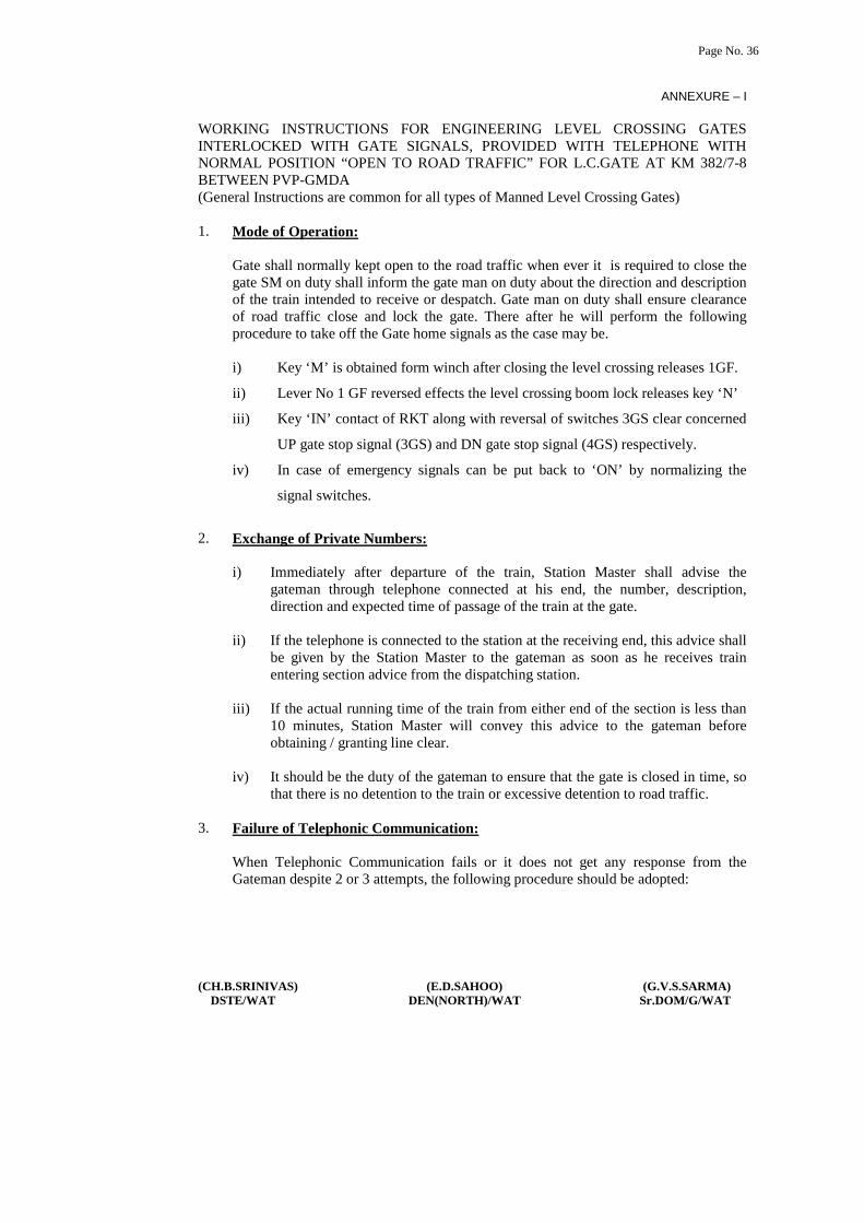
Page No. 36
(CH.B.SRINIVAS) (E.D.SAHOO) (G.V.S.SARMA)DSTE/WAT DEN(NORTH)/WAT Sr.DOM/G/WAT
ANNEXURE – I
WORKING INSTRUCTIONS FOR ENGINEERING LEVEL CROSSING GATESINTERLOCKED WITH GATE SIGNALS, PROVIDED WITH TELEPHONE WITHNORMAL POSITION “OPEN TO ROAD TRAFFIC” FOR L.C.GATE AT KM 382/7-8BETWEEN PVP-GMDA(General Instructions are common for all types of Manned Level Crossing Gates)
1. Mode of Operation:
Gate shall normally kept open to the road traffic when ever it is required to close thegate SM on duty shall inform the gate man on duty about the direction and descriptionof the train intended to receive or despatch. Gate man on duty shall ensure clearanceof road traffic close and lock the gate. There after he will perform the followingprocedure to take off the Gate home signals as the case may be.
i) Key ‘M’ is obtained form winch after closing the level crossing releases 1GF.
ii) Lever No 1 GF reversed effects the level crossing boom lock releases key ‘N’
iii) Key ‘IN’ contact of RKT along with reversal of switches 3GS clear concerned
UP gate stop signal (3GS) and DN gate stop signal (4GS) respectively.
iv) In case of emergency signals can be put back to ‘ON’ by normalizing the
signal switches.
2. Exchange of Private Numbers:
i) Immediately after departure of the train, Station Master shall advise thegateman through telephone connected at his end, the number, description,direction and expected time of passage of the train at the gate.
ii) If the telephone is connected to the station at the receiving end, this advice shallbe given by the Station Master to the gateman as soon as he receives trainentering section advice from the dispatching station.
iii) If the actual running time of the train from either end of the section is less than10 minutes, Station Master will convey this advice to the gateman beforeobtaining / granting line clear.
iv) It should be the duty of the gateman to ensure that the gate is closed in time, sothat there is no detention to the train or excessive detention to road traffic.
3. Failure of Telephonic Communication:
When Telephonic Communication fails or it does not get any response from theGateman despite 2 or 3 attempts, the following procedure should be adopted:

Page No. 37
(CH.B.SRINIVAS) (E.D.SAHOO) (G.V.S.SARMA)DSTE/WAT DEN(NORTH)/WAT Sr.DOM/G/WAT
i) If the telephone falls at the gate connected with the station at the despatchingend, Station Master shall issue a caution order to the Loco Pilot of the departingtrain.
ii) Station Master shall advise the Loco Pilot to whistle continuously and proceedcautiously while approaching the gate.
iii) In case the gate signal is ‘ON’ he should stop short of the gate signal and followthe procedure laid down under GR 3.73.
iv) In case of an approaching train, the Station Master shall advise the StationMaster at the dispatching end, under exchange of private number, that thetelephone at the gate has failed.
v) The Station Master at the dispatching end shall then issue a caution order to theLoco Pilot before dispatching a train in the block section from his end.
vi) Station Master will also advise the gateman through Gangman / Patrolman /Loco Pilot of the first train that the telephone has become defective.
vii) Station Master should also advise S&T staff responsible for maintenance of thetelephone to rectify the same at the earliest.
viii) Normal working will be resumed only after S&T staff rectify the telephone andissue reconnection / fit memo for the same.
4. Failure of Lifting Barriers
i) When the gate cannot be closed due to failure of lifting barriers, the gatemanshall immediately inform the Station Master on duty under exchange of privatenumber, and ensure that lifting of barriers or leaf gates do not foul the track.
ii) He shall immediately fix red banner flag by day and red light by night on thepost at that end first from which the train is approaching and then at the otherend.
iii) Gateman shall secure that gate against road traffic by means of safety chainsand padlocks.
iv) After securing the gate against road traffic, gateman shall show green handsignal flag by day and green light to the Loco Pilot of the approaching train.
v) Station Master on duty shall issue caution order to the Loco Pilot of a departingtrain.
vi) He shall also advise the Station Master at the dispatching end, under exchangeof private number; to similarly issue a caution order to the Loco Pilot beforedespatching a train in the block section.

Page No. 38
(CH.B.SRINIVAS) (E.D.SAHOO) (G.V.S.SARMA)DSTE/WAT DEN(NORTH)/WAT Sr.DOM/G/WAT
vii) Station Master shall advise maintenance staff responsible for maintaining thelifting barrier to rectify the same at the earliest.
viii) Normal working will be resumed only after maintenance staff repair the liftingbarrier and issue reconnection / fit memo for the same.
5. Failure of Gate Key with the gate in closed position, when Gate Key cannot beextracted for opening the gate:
i) If the gate key cannot be extracted from the winch, gate signal lever or keytransmitter then gateman must immediately inform the Station on duty ontelephone, under exchange of private number.
ii) If Emergency Key is available at the gate lodge / cabin, Gateman will take it outfrom the sealed box by breaking the seal and open the gate for road traffic.
iii) The record of the date and time of breaking the sealed cover of Emergency keyBox shall be recorded and signed with reasons.
iv) Thereafter, the gate must be treated as non-interlocked and procedure forreception / despatch of trains as prescribed for non-interlocked gates, should beadopted.
v) Station Master on duty shall issue caution order to the Loco Pilot of a departingtrain.
vi) He shall also advise the Station Master at the dispatching end, under exchangeof private number, to similarly issue a caution order to the Loco Pilot beforedespatching a train in the block section from his end.
vii) Station Master shall advise S&T staff responsible for maintaining the keytransmitter to repair the same at the earliest.
viii) Normal working will be resumed only after S&T staff repair the key transmitterand issue reconnection / fit memo for the same.
ix) After rectification, the Emergency key shall be replaced in the Emergency KeyBox and resealed by the S&T maintainer.
6. Failure of the Gate Key with the gate in open condition:
i) If the gate key cannot be extracted from the winch, gate signal lever or keytransmitter then gateman must immediately inform the Station Master on dutyon telephone, under exchange of private number.
ii) Thereafter, the gate must be treated as non-interlocked and procedure forreception / despatch of trains as prescribed for non-interlocked gates, should beadopted.

Page No. 39
(CH.B.SRINIVAS) (E.D.SAHOO) (G.V.S.SARMA)DSTE/WAT DEN(NORTH)/WAT Sr.DOM/G/WAT
iii) The gateman shall secure the gate against road traffic by means of chains andpadlocks and pass trains on hand signals.
iv) Station Master on duty shall issue a caution order to the Loco Pilot of adeparting train.
v) He shall also advise the Station Master at the despatching end, under exchangeof private number, to similarly issue a caution order to the Loco Pilot beforedispatching a train in the block section from his end.
vi) Station Master shall advise S&T staff responsible for maintaining the keytransmitter to repair the same at the earliest.
vii) Normal working will be resumed only after S&T staff repair the key transmitterand issue reconnection / fit memo for the same.
viii) After rectification, the Emergency key shall be replaced in the Emergency KeyBox and resealed by the S&T maintainer.
7. Defective Gate Signals:
i) The gateman shall treat the gate as defective and must not lower them underfollowing circumstances:
a) If gate signals can be taken ‘OFF’ without closing the gate, or
b) The key can be extracted from the operation winch when the gate is inopen condition, or
c) The key can be extracted from the leaf gates when the gate is in opencondition
ii) If the Gate or the Gate Signal or Warner / Distant Signal becomes defective in‘OFF’ position, the gateman will make all efforts to put it at ‘ON’ position evenby cutting signal wires, if necessary.
iii) The gateman will immediately advise the Station Master on duty, underexchange of private number, regarding defective gate signals.
iv) Thereafter, the gate must be treated as non-interlocked and procedure forreception / dispatch as prescribed for non-interlocked gates should be adopted.
v) He shall show green hand signal flag by day and green light by night to thepassing train after closing the gate.
vi) Station Master on duty will issue a caution order to the Loco Pilot of adeparting train.

Page No. 40
(CH.B.SRINIVAS) (E.D.SAHOO) (G.V.S.SARMA)DSTE/WAT DEN(NORTH)/WAT Sr.DOM/G/WAT
vii) He shall also advise the Station Master at the dispatching end, under exchangeof private number, to similarly issue a caution order to the Loco Pilot beforedespatching a train in the block section from his end.
viii) Station Master shall advise S&T staff responsible for maintaining the gatesignal to repair the same at the earliest.
ix) Normal working will be resumed only after S&T staff rectify the defective gatesignal and issue reconnection / fit memo for the same,
8. Obstruction at the Gate:
i) If the gate is broken by road vehicle which is fouling the track, or if liftingbarriers or any other part of the gate foul the track, or if there is any otherobstruction at the gate, the gateman shall immediately put back gate signals to‘ON’ position.
ii) He shall fix red banner flag by day and red lamp by night on posts provided atboth ends of the gate for this purpose.
iii) Immediately after this, the gateman shall advise the Station Masteron dutyregarding the defects / obstructions at the gate, under exchange of privatenumber.
iv) If there is no response from the Station Master after two or three attempts, heshall first protect the gate and then inform on phone.
v) Gateman shall then rush with detonators, and red flag by day and red handsignal lamp by night in the direction of the approaching train and protect thegate as stipulated in General Instruction for duties of gateman under item no.1.5(5).
vi) Thereafter he shall protect the gate from the other direction also.
vii) He shall note down the particulars of the road vehicle, name of the driver,owner and relay these details to the Station Master who shall not start the trainunless he has been assured by the gateman that the road vehicle or the liftingbarriers / leaf gates are not fouling the track.
viii) The Station Master shall also inform the Station Master at the despatching end,under exchange of private number, asking him not to despatch any train in theblock section from his end, until the track has been cleared of all obstruction.
ix) After the track has been cleared of all obstructions the gateman shall inform theStation Master accordingly, under exchange of private number.
x) Station Master shall then issue a caution order to Loco Pilot of all trains toproceed cautiously, and pass the gate signal at ‘ON’ position on green handsignal of the gateman, of the gate is broken, but is clear of any obstruction.
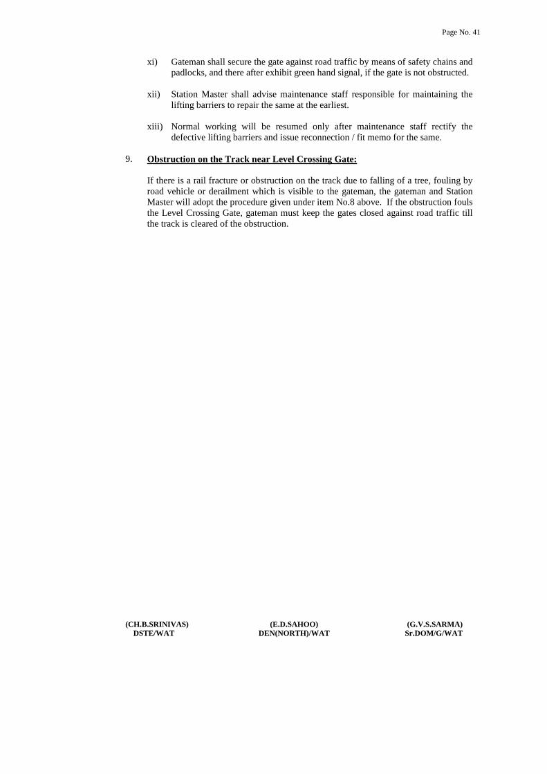
Page No. 41
(CH.B.SRINIVAS) (E.D.SAHOO) (G.V.S.SARMA)DSTE/WAT DEN(NORTH)/WAT Sr.DOM/G/WAT
xi) Gateman shall secure the gate against road traffic by means of safety chains andpadlocks, and there after exhibit green hand signal, if the gate is not obstructed.
xii) Station Master shall advise maintenance staff responsible for maintaining thelifting barriers to repair the same at the earliest.
xiii) Normal working will be resumed only after maintenance staff rectify thedefective lifting barriers and issue reconnection / fit memo for the same.
9. Obstruction on the Track near Level Crossing Gate:
If there is a rail fracture or obstruction on the track due to falling of a tree, fouling byroad vehicle or derailment which is visible to the gateman, the gateman and StationMaster will adopt the procedure given under item No.8 above. If the obstruction foulsthe Level Crossing Gate, gateman must keep the gates closed against road traffic tillthe track is cleared of the obstruction.

SWR of PARVATIPURAM 1
[CH.B.SRINIVAS] [G.V.S.SARMA]DSTE/WAT Sr.DOM(G)/WAT
APPENDIX – B TO STATION WORKING RULES OF PARVATIPURAM STATION.
DETAILS OF SIGNALLING AND INTERLOCKING INSTALLATIONS,INSTRUCTIONS FOR WORKING THEM NORMALLY AND IN EMERGENCIESETC, INCLUDING POWER SUPPLY ARRANGEMENTS.
1.1 BRIEF DESCRIPTION OF THE SIGNALLING AND INTERLOCKINGINSTALLATIONS:
This is a “B” Class Station with standard-III interlocking (with isolation). The points andsignals are power operated from a composite ‘DOMINO TYPE’ full-fledged panel installedin the SS/Dy.SS office. This station is equipped with panel operated MACLS. The SGEtype double Line lock and Block Instruments are provided in the SS/Dy.SS panel room forsection PVP- GMDA and PVP-SNM adjacent to the panel.
1.2 DESCRIPTION OF PANEL:
The yard lay out is depicted in the panel board and is fixed parallel to the track so that whenthe SM on duty faces, the Yard drawing on the panel corresponds to the actual field lay outin either direction.
1.3 POINT BUTTONS:
Each point is provided with Push buttons (Black in color) for individual operation of Points.For operation of point to normal/reverse position, Point group push buttons (black with reddot) are provided. Point button and Point Group button normal/reverse shall be pressed atthe same time for operation of point to required position. To indicate the position of point, awhite steady strip on Normal direction to indicate normal position of point, and a whitesteady strip on Reverse direction to indicate Reverse position of point.
1.4 When a point is set and locked correctly in normal position, a white steady strip indicationon normal point zone appears suggesting that the point is in normal position and locked inits position.
1.5 When a point is set and locked correctly in Reverse position, a white steady strip indicationon reverse point zone appears suggesting that the point is in Reverse position and locked inits position.
1.6 When the point is operated from reverse to normal position, a white strip indication onnormal point zone will start flashing till the concerned point is set and locked in normalposition. When the point is operated from normal to reverse, a white strip indication onreverse point zone will start flashing till the concerned point is set and locked in reverseposition.

SWR of PARVATIPURAM 2
[CH.B.SRINIVAS] [G.V.S.SARMA]DSTE/WAT Sr.DOM(G)/WAT
1.7 OPERATION OF POINTS:
Points are operated to normal or Reverse by pressing individual point button in conjunctionwith the point group button there by the white strip indication on normal point zone orreverse point zone as the case may be till the points are set to normal or reverse position andlocked. Then the white steady strip indication on normal point zone and white steady stripindication on reverse point zone will appear as the case may be. During the automatic routesetting of the train operation, the same indication will glow.
1.8 All running line points are operated by Electric point machine.
2.0 The course for non-setting of the point in the desired position has to be checked up by theSS/Dy.SS on duty according to G & SR 3.68.01(c) and if there is a defect other thanobstruction the point has to be considered as defective and action shall be taken forclamping and pad locking these points in the desired position by the SS/Dy.SS on dutyhimself for all trains according to SR 3.69.03(c).
2.1 DESCRIPTION OF POINTS:
Sl.No
Point Button No. Color Description
1 17 Black Cross over point between Up & Dn main line atRaipur end.
2 19 Black Cross over point between Dn main & commonloop line at Raipur end.
3 21 Black Cross over point between Up main & Up loopline at Raipur end.
4 18 Black Cross over point between Up & Dn main line atVZM end.
5 20 Black Cross over point between Dn main & DN loopline at VZM end
6 22 Black Cross over point between Up main & Up loopline at VZM end
7 Point groupbutton (Normal)
Black withred dot.
Common button for normal operation of points.
8 Point GroupButton (Reverse)
Black withRed dot.
Common button for Reverse operation ofpoints.

SWR of PARVATIPURAM 3
[CH.B.SRINIVAS] [G.V.S.SARMA]DSTE/WAT Sr.DOM(G)/WAT
3.0 SIGNAL BUTTONS:
Sl.No
Button No. Color Description
1 C1 Red withwhite dot
Up Calling ‘ON’ signal for Line no. 1,3 & 4.
2 S1 Red Up Home signal for line no.1, 3&4.3 C2 Red with
white dotDn calling ‘ON’ signal for line no. 1& 2.
4 S2 Red Dn Home signal for line no.1&2.5 S5 Red Up loop starter for line no.46 S6 Red Dn common signal for line no.17 S7 Red Dn Common loop starter for line no. 18 S9 Red Up main starter for line no. 3.10 S10 Red Dn main starter for line no. 211 S11 Red Up adv. Starter.12 S12 Red Dn Advance starter13 SH3 Yellow Shunt signal for line no. 1 & 2.14 SH4 Yellow Shunt signal for line no. 1, 2, 3 & 4.
3.1 SIGNAL INDICATION:
The aspect of signal as obtained at any time is shown on the panel on the Signal indication(along side of the track).
4.0 ROUTE BUTTONS:
Route buttons are provided separately on each running line on the panel for indication ofroute (viz L1UN, L1UN1, L2UN, L3UN, L4UN, and L4UN1). Common route buttons arealso provided for taking off starters 11 AT UN, 12 AT UN. An individual route button isprovided for taking off advance starter 12 UN, 11 UN. For clearing the signal, it isnecessary to operate the signal button and the concerned route button concurrently.
4.1 DESCRIPTIONS OF BUTTONS:
S.N Button No. Color Description1 L1 UN White Common route button for UP & DN Home signal
and UP & DN Calling-On signal for line no.1setting overlap on UP & DN main line.
2 L1 UN1 White withblack dot
Common route button for UP & DN Home signaland UP & DN Calling-On signal for line no.1setting overlap to over run line and route buttonfor DN. Shunt signal no. 4 & UP SH No-3 forline no. 1.
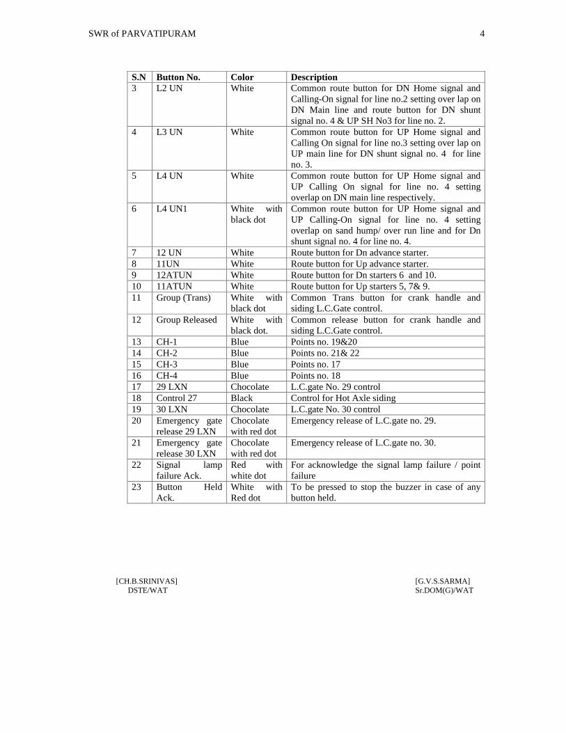
SWR of PARVATIPURAM 4
[CH.B.SRINIVAS] [G.V.S.SARMA]DSTE/WAT Sr.DOM(G)/WAT
S.N Button No. Color Description3 L2 UN White Common route button for DN Home signal and
Calling-On signal for line no.2 setting over lap onDN Main line and route button for DN shuntsignal no. 4 & UP SH No3 for line no. 2.
4 L3 UN White Common route button for UP Home signal andCalling On signal for line no.3 setting over lap onUP main line for DN shunt signal no. 4 for lineno. 3.
5 L4 UN White Common route button for UP Home signal andUP Calling On signal for line no. 4 settingoverlap on DN main line respectively.
6 L4 UN1 White withblack dot
Common route button for UP Home signal andUP Calling-On signal for line no. 4 settingoverlap on sand hump/ over run line and for Dnshunt signal no. 4 for line no. 4.
7 12 UN White Route button for Dn advance starter.8 11UN White Route button for Up advance starter.9 12ATUN White Route button for Dn starters 6 and 10.10 11ATUN White Route button for Up starters 5, 7& 9.11 Group (Trans) White with
black dotCommon Trans button for crank handle andsiding L.C.Gate control.
12 Group Released White withblack dot.
Common release button for crank handle andsiding L.C.Gate control.
13 CH-1 Blue Points no. 19&2014 CH-2 Blue Points no. 21& 2215 CH-3 Blue Points no. 1716 CH-4 Blue Points no. 1817 29 LXN Chocolate L.C.gate No. 29 control18 Control 27 Black Control for Hot Axle siding19 30 LXN Chocolate L.C.gate No. 30 control20 Emergency gate
release 29 LXNChocolatewith red dot
Emergency release of L.C.gate no. 29.
21 Emergency gaterelease 30 LXN
Chocolatewith red dot
Emergency release of L.C.gate no. 30.
22 Signal lampfailure Ack.
Red withwhite dot
For acknowledge the signal lamp failure / pointfailure
23 Button HeldAck.
White withRed dot
To be pressed to stop the buzzer in case of anybutton held.
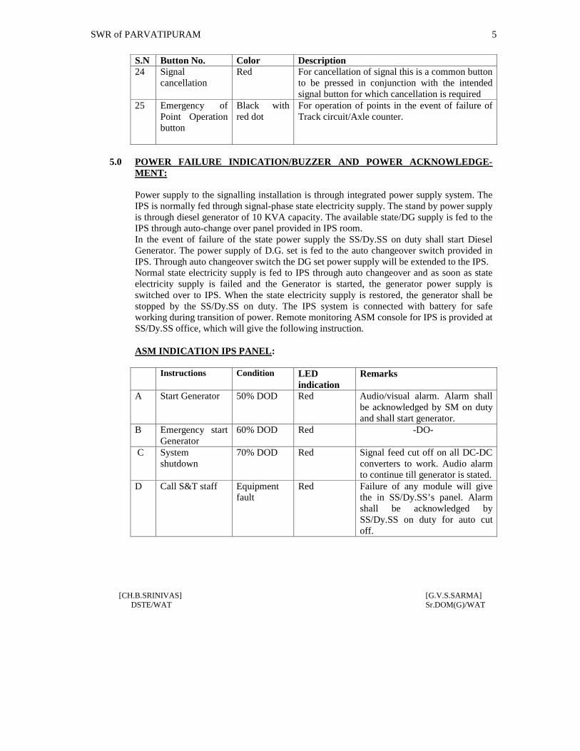
SWR of PARVATIPURAM 5
[CH.B.SRINIVAS] [G.V.S.SARMA]DSTE/WAT Sr.DOM(G)/WAT
S.N Button No. Color Description24 Signal
cancellationRed For cancellation of signal this is a common button
to be pressed in conjunction with the intendedsignal button for which cancellation is required
25 Emergency ofPoint Operationbutton
Black withred dot
For operation of points in the event of failure ofTrack circuit/Axle counter.
5.0 POWER FAILURE INDICATION/BUZZER AND POWER ACKNOWLEDGE-MENT:
Power supply to the signalling installation is through integrated power supply system. TheIPS is normally fed through signal-phase state electricity supply. The stand by power supplyis through diesel generator of 10 KVA capacity. The available state/DG supply is fed to theIPS through auto-change over panel provided in IPS room.In the event of failure of the state power supply the SS/Dy.SS on duty shall start DieselGenerator. The power supply of D.G. set is fed to the auto changeover switch provided inIPS. Through auto changeover switch the DG set power supply will be extended to the IPS.Normal state electricity supply is fed to IPS through auto changeover and as soon as stateelectricity supply is failed and the Generator is started, the generator power supply isswitched over to IPS. When the state electricity supply is restored, the generator shall bestopped by the SS/Dy.SS on duty. The IPS system is connected with battery for safeworking during transition of power. Remote monitoring ASM console for IPS is provided atSS/Dy.SS office, which will give the following instruction.
ASM INDICATION IPS PANEL:
Instructions Condition LEDindication
Remarks
A Start Generator 50% DOD Red Audio/visual alarm. Alarm shallbe acknowledged by SM on dutyand shall start generator.
B Emergency startGenerator
60% DOD Red -DO-
C Systemshutdown
70% DOD Red Signal feed cut off on all DC-DCconverters to work. Audio alarmto continue till generator is stated.
D Call S&T staff Equipmentfault
Red Failure of any module will givethe in SS/Dy.SS’s panel. Alarmshall be acknowledged bySS/Dy.SS on duty for auto cutoff.

SWR of PARVATIPURAM 6
[CH.B.SRINIVAS] [G.V.S.SARMA]DSTE/WAT Sr.DOM(G)/WAT
In the event of failure of Remote monitoring ASM console due to any reason when localpower is failed the SS/Dy.SS on duty shall start D.G set immediately. In case ‘ call S&Tstaff ’ or ‘ system shut down ‘ indication appear on the remote monitoring panel of IPS and/ or mal functioning of the remote monitoring panel SM on duty shall inform the same toconcerned S&T staff immediately.
5.1 SIGNAL LAMP FAILURE INDICATION (MUTING BUTTON RED WITH WHITEDOT]
Whenever signal lamp is fused, a miniature flashing Red light indication appears along withan audible buzzer indicates Signal lamp failure. Then SS/Dy.SS on duty shall press theAcknowledgment button thereby the buzzer stops but the Red indication lamp becomessteady which continues till either the signal lamp is replaced or signal assumes other aspect.Whenever auxiliary filament also fuses, the concern auxiliary lamps fusing Red indicationlamp flashes and auxiliary buzzer start buzzing. The SS/Dy.SS on duty shall press the signallamp Failure Acknowledgement button thereby the buzzer stops but the Red signalindication lamps becomes steady which continues till either the signal lamp is replaced orsignal assumes other aspect. Whenever main filament is fused, SS/Dy.SS on duty shallimmediately send message to SE/ESM for rectification.
5.0 BUTTON FAILURE INDICATION WHITE/BUTTON HELD BUZZER WHITEWITH RED DOT:
Whenever any button remains held up in pressed condition ‘Button Held’ white. Indicationstarts flashing along with an audible buzzer. The SM on duty then acknowledge it bypressing the “Button Held” push button (white with red dot) the buzzer stop but the whiteindication continues to flash till the same is rectified.
6.0 TRACK CIRCUIT/AXLE COUNTER:
At this station all the berthing lines i.e. loop lines and main lines and point zones areprovided with track circuits to indicate the occupation/ clearance of berthing/point zoneportion. Starters will automatically be replaced by the point zone track circuits. Last VehicleTrack (LVT) and First Vehicle Track (FVT) circuits are provided near Home and advancestarter signals for their automatic replacement and release of block instruments. In addition90 Mtrs rail length track circuits are provided in advance of Up and Dn home signals forcontrol of calling on signals. The occupation/ clearance of track circuits indication isprovided on the indication cum operating panel installed at station.
6.1 When a train is to be dispatched from the station yard on signals the SS/Dy.SS on Dutymust ensure that the route between the starter signal and the block section limits demarcatedby the Advance Starter is clear of any obstruction (which includes point zones trackcircuits) before he takes off departure signals.
SWR of PARVATIPURAM 7
[CH.B.SRINIVAS] [G.V.S.SARMA]DSTE/WAT Sr.DOM(G)/WAT
6.2 CRANK HANDLE FOR EMERGENCY OPERATION OF POINTS CRANK:
Crank handle is inter locked with the signaling and inter locking system at this station andthe crank handle which is normally locked up in the RKT instrument in the goomties at theboth End of the yards can be taken out when the signals on the connected route are innormal position and the route is not locked for any reason.Even when the route is locked the crank handle key can be extracted from the RKT throughemergency operation by pressing the concerned crank handle button along with group Transbutton concurrently. When this operation is resorted, the crank handle ‘Key in’indication(white) and locked indication (Red) both start flashing. After 120 Second offlashing of both, the locked indication (Red) disappears. Similarly such red indicationappears at the crank handle location at site near corresponding RKT and now the crankhandle key can be taken out from the RKT at site, After key extracted at site from the RKT,the key in indication (white) on panel, board will extinguish. After completion of work,crank handle key shall be restored to RKT which will be indicated by flashing key in(white) indication on panel board, which comes steady only after pressing of concernedcrank handle button along with group release button concurrently.
6.3 On account of the doubtful operation of any track circuit by light vehicle/ vehicle includingself propelled vehicles such as motor trolley or a diesel shunting engine or a tower wagon,in indication of the occupancy of the track it is necessary that the SS/Dy.SS on dutysatisfied himself that the said vehicle/ vehicles has/have cleared the point zone track circuitsby observing the track indication of the tracks on either side of the cross over by positivelychecking of the ENTRANCE and EXIT track circuit are showing occupancy and clearancein accordance with the train movement.
7.0 STATION MASTER’S KEY:
The panel is also fitted with SS/Dy.SS’s lock up key to prevent unauthorized operation ofthis panel but with the arrangement to put back the signal to the ON position in the case ofemergency without altering the route when the panel is locked position.
8.0 EMERGENCY OPERATIONS:
The following are the instructions for Emergency operations.
8.1 ROUTE CANCELLATION
For the purpose of the emergencies operations there is an emergency Route cancellation andalso there is a veeder counter for counting emergency operations involving the concurrentoperation of the emergency route cancellation button. The SS/Dy.SS on duty must press theemergency route button along with concerned signal button for which emergency routerelease is required. An yellow indication will appear below the signal indicating that thetimer has started operation and after lapse of 120 seconds. The desired route will bereleased provided all other conditions are favorable for the route release.

SWR of PARVATIPURAM 8
[CH.B.SRINIVAS] [G.V.S.SARMA]DSTE/WAT Sr.DOM(G)/WAT
8.2 SIGNAL CANCELLATION
For the purpose of throwing the signal to danger in case of emergency, press concernedsignal button along with common signal cancellation button. Then the signal will fly back toon position.
The numbers on the veeder counter register the number of operations performed for suchemergency cancellation and the SS/Dy.SS on duty should specify the cause for such usagegiving the particulars of cause and the time of operation as related to a particular train etc inthe train signal register. The detailed operation instructions are as follows:
8.3 CANCELLATION OF UNINTENDED LOCK ING OF POINTS.
When ever there is un intended locking of any points (indicated by RED indication lampnear the concerned point) such a locking has to be released (after the concerned signal are inthe normal position) by concurrently pressing the Emergency Group cancellation button(provided at the counter of the panel) and the concerned signal button provided the trackcircuits are clear and are in working condition. This operation is counted on the veedercounter/counter as already pointed out.
8.4 CANCELLATION OF LOCKING OF ROUTE AND POINTS AFTER THE SIGNALHAS BEEN PUT BACK TO ‘ON’ORTHE SIGNAL HAS GONE BACK TO ON EITHER AFTER THE MOVEMENT OF THETRAIN IS CANCELLED
ORTHE TRAIN HAS COME TO A STOP OUT SIDE THE STOP SIGNALIn case the route is set and the signal is taken off and if it is warranted that the signal has tobe put back to ON and cancel the route.
a) Firstly the signal has to be put back to the ON positionb) Emergency route cancellation operation must be initiated as detailed in para 8.1.
8.5 EMERGENCY OPERATIONS:
Cancellation of the locking of points not released after the passage of the train for anyreason.If the locking of the route does not get released for one reason on the other afterpassage of the train, it is necessary to take recourse to the following emergency operation.
a) Firstly it must be ensured that the signal and signal buttons are in the normal position.b) Operation as details in para 8.1 to be followed.

SWR of PARVATIPURAM 9
[CH.B.SRINIVAS] [G.V.S.SARMA]DSTE/WAT Sr.DOM(G)/WAT
9.0 EMERGENCY OPERATION OF POINTS (IN CASE OF POINT ZONE TRACKCIRCUIT FAILURE):
The SS/Dy.SS on duty can operate points from panel; in case of point zone track circuitfails. The Station Master on duty after physical verification insert the SS/Dy.SS’semergency point key and turn into get the key. ‘N’ position keeping the Emergency pointkey in that position the SS/Dy.SS on duty must press the individual point button alongwith emergency point operation button (Black with Red dot). He shall then release theemergency point operation button only and press the point group Normal or Reversebutton as per requirement keeping the individual point button is pressed condition. Pointswill be set to Normal or Reverse position as per operation. During the initiation REDindication will appear above the emergency operation button. This operation will beregistered in emergency point operation counter placed the emergency point operationbutton will increase in number by one.
10.0 INTER LOCKING OF SIGNALS:
All running line points are fitted with point machine and all are electrically detected bythe relevant Home signals and starters.
Advance starters are interlocked with respective double line block instrument in LINECLEAR position.
Home signals are interlocked with respective Double Line block instrument. TheBlock instruments cannot be made to normal unless the respective Home signals are inNormal position.
Signals once taken OFF can be put back to Danger in case of emergency by pressing theconcerned signal button in conjunction with signal cancellation button even when thepanel is locked up with SS/Dy.SS.
11.0 LOCKING OF RELAY ROOM:
i) Relay room at this station is provided with double locks (Two independent locks)as necessary vide OM 1.14 one key shall be kept with the Signal Maintainer of thesection and the other with Station Master on duty. The relay room cannot beopened unless both keys are used.
ii) The SS/Dy.SS shall ensure that the Relay Room key is given to S&T maintenancestaff under clear signature as and when required for their normal maintenance andspecial works and that the key should be returned by the S&T staff immediatelyafter completion of their work and the documentation should be made in the RelayRoom key register maintained at the Station according to SR 3.51.05 and OM 1.14.

SWR of PARVATIPURAM 10
[CH.B.SRINIVAS] [G.V.S.SARMA]DSTE/WAT Sr.DOM(G)/WAT
12.0 MAINTENANCE OF S&T INSTALLATION AND ADHERENCE TOMAINTENANCE SCHEDULES:
i) The regular maintenance of the S&T installation and adherence to the schedules ofMaintenance as also to the mandatory schedules of testing of Points, TrackCircuits, Signals, Ground Frames, Level Crossing Gates, the associated interlocking apparatus i.e. Cables and finally the interlocking functional tests is a mustfor the safe and satisfactory working these installations at the Station.
ii) The tests, checks and re-placement etc., including overhauling shall confirm to theSchedules of the maintenance as indicated in the Signal Engineering Manual asalso in the current and extent instructions/Circulars on the subject.
13.0 PROCEDURE TO BE FOLLOWED IN CASE OF FAILURE OF SIGNALINTERLOCKING INSTALLATION:
Whenever there is failure of Points, Track Circuits, Signals , Axle-counters Or any otherinterlocking gear at the Station, the failure report should communicated by the SS/Dy.SSon duty through a Memo to the sectional Maintainer and the Signal Inspector of thesection along with others as per G & SR 3.51.04 and 3.68.04 and document all suchtransactions.
14.0 INSPECTION OF POINTS BEFORE DELCARING THEM DEFECTIVE:
However, before declaring as Signal defective the setting of the Point on the route towhich It applies shall be inspected by the Station Master on duty irrespective of theposition of the Switches on the Panel in terms of SR 3.68.04(c).
14.1 RECTIFICATION AND CHECK BEFORE RESUMING NORMAL WORKING:
It is only after receipt of this information the sectional Maintainer [Electrical OrMechanical] shall attend to the failure after giving a disconnection Memo. Afterrectification of the fault, the sectional maintainer shall give a re-connection MemoDetailing the rectification and it is only after the Station Master on duty has personallychecked this defective gear and is satisfied that it is in good and proper working order. Heshall resume the normal working of the said defective gear in terms of SR 3.68.04[c] and[d].
15.0 PROCEDURE FOR CARRYING OUT PLANNED MAINTENANCE WORKS:
However any normal maintenance or special works for heavy renewals etc., are involved,These works should be pre-planed by the Signal and Telecom filed staff and the Inspectorof the section should give to the Station Master in writing “Advance intimation” aboutthis planned work in terms of G & SR 15.08.01.

SWR of PARVATIPURAM 11
[CH.B.SRINIVAS] [G.V.S.SARMA]DSTE/WAT Sr.DOM(G)/WAT
16.0 EMERGENCIES:
Not with standing any thing contained in the afore-said Para Nos. 14.1, 14.2 and 14.3when a Gear is found to be defective and un-safe for passage of trains, the Signal &Telecom staff must at once suspend the working of that gear and the associatedinstallations and issue a “ Suspense Memo” explaining the seriousness of the defect OrDamage to the interlocking installation to the SS/Dy.SS and take SS/Dy.SSacknowledgment. After this, the usual practice of exchange of disconnection memo andre-connection Memo can follow and the SS/Dy.SS must promptly act on such massagesand take adequate precautions treating the S&T installation as defective and pass trainsover the effected interlocking gears according to extent instructions as contained in G R3.77 and SR thereon.
17.0 SIGNAL LIGHTS:
The SS/Dy.SS on duty at every shift must also ensure from Panel Board that all the Signallights are Burning properly and brightly. This fact must be recorded in the diary under aseparate entry and confirm to the section controller on duty as per the instructionscontained in Divisional Safety Circular No. 82/82, Dated 2.5.82 and GR 3.49(3).
18.0 CORRECTING TIME IN THE STATION CLOCKS:
The SS/Dy.SS shall set the time on his Clock according to the time Signal given by thesection Controller on duty at 16.00 hours every day according to G & SR 4.01.01 and4.01.02
19.0 NORMAL POWER SUPPLY:
The Station works on 230 Volts single-phase power supply. The normal power supply isfrom the State electricity local supply.
19.1 STANDBY POWER SUPPLY:
Diesel generator supply is available at the Station as stand by with changeover switcharrangement.
19.2 NORMAL POWER SUPPLY-MAINTENANCE OF POWER SUPPLY, POWERFAILURE AND REPORTING SUCH FAILURES:
Normal power supply to the Signaling and Interlocking installations at this station Isdrawn from the State electricity supply sources [at 230-V-50HZ]. The SS/Dy.SS musthowever, maintain the record of the power failure of the local supply and he mustpromptly report the failure immediately to the Section Controller and to the concernedElectrical and S&T maintenance Staff.

SWR of PARVATIPURAM 12
[CH.B.SRINIVAS] [G.V.S.SARMA]DSTE/WAT Sr.DOM(G)/WAT
20.0 WORKING OF POINTS – POSITION OF POINTS:
The normal position of all points shown in the Station Working Rule Diagram No.SI/WRD 23018 Alt. A and also in the mimic indication panel provided in the StationMasters office.
20.1 All cross over points and independent points on the running lines are worked by ElectricPoint Machines. The point machines have in-built locking and detection arrangements.These points are remotely controlled from the panel situated in the SS/Dy.SS’s office.
20.2 The operation and indication on the points and their route locking over them is alreadyexplained in earlier pares of Appendix-B.
20.3 All siding entrance points (on the running lines) and the corresponding derailing switcheson the siding are coupled and locally operated by hand levers provided at site. Theentrance points are provided with hand plunger locks with key locking arrangements, thekey being released from the RKT instruments. The siding entrance points controlling keyis inter locked with the interlocking and signaling system through the RKT as explained inearlier pares of Appendix-B.
21.0 PROCEDURE TO BE FOLLOWED IN CASE OF FAILURE OF SIGNAL POINTSAND USE OF EMERGENCY CRANK HANDLE:
21.1 Whenever a Signal or a Point become defective any movements over the Points on therunning lines should be made after clamping and padlocking both the facing and trailingPoints by SS/Dy.SS on duty personally for all trains at the Station.
21.2 In case of failure of Signal or a Point and in case the Point can not be operated from thePanel, the emergency Crank Handle which is Interlocked with the system has to beextracted and the following procedure has to be observed.
21.3 In case of failure of any point, Crank Handles are provided for setting of the pointsmanually. For this operation procedure mentioned in para No.6.2 shall be followed.
21.4 The case of failure of Motor Operated Points should be promptly reported to theconcerned Signal Inspector/ESM for immediate rectification.
21.5 Whenever an emergency Crank Handle is required to be used by a Signal Official formaintenance of work attending to failure, the Signal Official will give a disconnectionmemo to the SS/Dy.SS on duty and after making necessary entries in the emergencyCrank Handle register, the Station Master on duty will obtain acknowledgement of theSignal Official in the emergency Crank Handle Register and than handover to him theemergency Crank Handle for the Points concerned. All the Points will be treated asdefective till the Emergency Crank Handle is returned back to Station Master on duty.21.2

SWR of PARVATIPURAM 13
[CH.B.SRINIVAS] [G.V.S.SARMA]DSTE/WAT Sr.DOM(G)/WAT
21.6 Before parting with the Emergency Crank Handle either for attending failure or forMaintenance work by Signal Maintenance Officials, the SS/Dy.SS on duty will ensurethat the reception and departure Signals are put back to on position. The Points of all thelines should be treated as Non-interlocked and the Station Master on duty is responsiblefor introduction of Non-interlocked working and the trains will piloted IN and OUTduly clamping and Padlocking the Points, both in facing and trailing directions overwhich the train is to pass, as per GR 3.69 and 3.70 with relevant SR’s. The SS/Dy.SS onduty will be personally responsible for setting and locking of Points, for reception anddispatch of all trains.
21.6.1 The Emergency Crank Handle Register is to be maintained in the following proforma bythe SS/Dy.SS on duty wherein the particulars of usage of the Emergency Crank Handlemust be recorded:1. Date:2. Point Number which failed or required to be tested:3. Time failure:4. Disconnection memo number received from S&T Staff:5. Signature of SM/Signal Official to whom the Emergency Crank Handle is
handed over:6. Time Emergency Crank Handle is sent out:7. Individual Point numbers, and Line number nominated for admission of dispatch
for which Points are set, Clamped and Padlocked:8. Train number to be admitted or dispatched:9. Signature of the SS/Dy.SS on duty to ensure correct setting, Clamping and
Padlocking of the Points:10. Date and Time fault rectified.11. Time of Emergency Crank Handle received back by SS/Dy.SS on duty:12. Signature and Designation of the Signal Official who rectified the fault:
IMPORTANT NOTE:
When performing shunting operations in the sidings it must be clearly noted that thesiding Points are interlocked with the system in the NORMAL position of the Pointsand in REVERSED position they are not interlocked. The Official responsible forshunting operation must clamp the Points at the both ends before permitting anymovement.
22.0 INTERLOCKING OF SIGNALS WITH BLOCK INSTRUMENTS:
22.1 INTERLOCKING WITH HOME SIGNALS:
All the UP and DOWN HOME Signals are Electrically interlocked with the respectiveDLBI so that before the handle of the DLBI Instrument can be turned from TOLposition to LINE CLOSED position, all the switches controlling the Home Signals ofUP or DOWN direction as the case may be must be in their NORMAL position.

SWR of PARVATIPURAM 14
[CH.B.SRINIVAS] [G.V.S.SARMA]DSTE/WAT Sr.DOM(G)/WAT
22.2 The UP and DOWN Advanced Starter Signals are Electrically interlocked withrespective DLBI so that these Signals can not be taken OFF until the Handle of theconcerned Block Instrument is in Line Clear position.
22.3 SUSPENSION OF LAST STOP SIGNALS:
When the Double line block instrument is suspended with its handle in any position forwhatever reason the concerned Last Stop Signals controlled by the DLBI must betreated as suspended and trains shall be PLCT & Piloted Out.
23.0 BURNING OF SIGNAL LIGHTS:
The SS/Dy.SS on duty shall not grant LINE CLEAR UN-lees he has ensured that theLamps of fixed Signals that apply to the train are burning brightly. If the Signal Lightscannot Kept burning the Station Master on duty shall before giving LINE CLEARinitiate action in accordance with the procedure prescribed in GR 3.68 To 3.72 andrelevant SR’s vide GR 3.49 (4).
24.0 LAST VEHICLE VERIFICATION (LVV) BY BLOCK PROVING TROUGHAXLE COUNTER :
Electronic Axle Counter have been provided between dispatching stations advancedstarter signal and first stop signal of receiving stations between PVP – SNM and PVP-GMDA sections on Up & Down lines. Complete arrival of trains at respective stationsis proved by these devices (BPAC). The status of the block section that is occupied orclear is indicated by the indications provided on the domino panel and on reset box. Theadvanced starter is controlled by the Clarence of the LV Axle counter section(BPAC).Clearance of LV Axle counter section is proved in the respective Block control cct. aswell as in block release cct. In case of failure of LV Axle counter line clear can not begranted through block instrument. Also in case of such failures on arrival of train blockinstrument can not be normalised.Whenever after complete arrival of train the LVCD axle counter continue to show Redon the panel Board. The on duty SS/Dy.SS at PVP station shall resort to the reset of theaxle counter.For this purpose SS/Dy.SS at PVP Station shall fist verify the block section is clear oftrain if the failure has occurred after arrival of train, SS/Dy.SS shall obtain signaturefrom the Guard of stopping train on the train intact register [vide GR&SR No.4.17,4.17..01] or by exchanging alright signal with the Guard of through train, so that he canensure that the train has arrived completely before resetting of LVCD axle counter fromSS/Dy.SS of SNM for Up Block Section and GMDA for DN block section.
Before resorting to the resetting of the LV axle counter (BPAC) SS/DY.SS of thereceiving station shall ensure complete arrival of train by means of physical verificationand as per the practice in vogue by deputing concerned operating official.

SWR of PARVATIPURAM 15
[CH.B.SRINIVAS] [G.V.S.SARMA]DSTE/WAT Sr.DOM(G)/WAT
One reset box for each LV axle counter (BPAC) has been provided in the panel room.There are three indications on the reset box i.e Red, yellow and Green. The clearanceand occupation of the block section is proved by the Green and Red indicationsrespectively as on the panel. Yellow indication which is called PPR indication, provesthat resetting operation has been initiated. One reset key and one reset button are alsoprovided on the reset box for resetting.. After complete train arrival is ascertainedSS/Dy.SS on duty at receiving end shall confirm the same to the dispatching endSS/Dy.SS supported by a PN and shall request for preparatory resetting of axle counter.SS/Dy.SS on duty at both end shall adopt the following procedure simultaneously.
SS/Dy.SS on duty at both end shall press the reset button, then turn and press the resetkey, then first release the reset button and then release the reset key. After this operationis completed, at both ends of the station PPR indication (yellow) will appear on the resetbox and one number will increase in the reset counter which is provided on the reset boxat both stations. SS/Dy.SS shall record the counter number in the A/C reset register withreason for resetting.
When ever LV axle counter (BPAC) fails first train has to be piloted out aftercompletion of the resetting procedure. On arrival of the first piloted train, the LV axlecounter section will show clear automatically by indicating Green on Reset Box and onoperating panel.
Even after above resetting procedure, if the section is not shown clear, on dutySS/Dy.SS shall inform concerned S&T staff immediately. Till such time the system isrectified, the absolute block working shall be suspended and the trains shall be workedas per relevant para of G.SR & BWM.
All reset keys shall be kept in the personal custody of SS/Dy.SS on duty.
25.0 Panel interlocking with last vehicle verification by Axle counter will be commissionedas per SI/WRD/23018 Alt ’A’ and the item No.24 of Appendix-‘B’ will be followedaccordingly after commissioning of last vehicle proving by Axle counter (BPAC). Lastvehicle will be verified physically till last vehicle cheking device (BPAC) iscommissioned.

SWR of PARVATIPURAM 1
[CH.B.SRINIVAS] [G.V.S.SARMA]DSTE/WAT Sr.DOM(G)/WAT
APPENDIX ‘C’ TO STATION WORKING RULES OF PARVATIPURAM STATION.
ANTI COLLISION DEVICE [RAKSHA KAVACH]
Not applicable to this Station.

SWR of PARVATIPURAM 1
[CH.B.SRINIVAS] [G.V.S.SARMA]DSTE/WAT Sr.DOM(G)/WAT
APPENDIX-‘D’ TO STATION WORKING RULES OF PARVARIPURAM STATION.
The following staff are concerned with the movement of the trains whose duties are givenbelow:
1.0 DY. STATION SUPERINTENDENT:
He is restored for 8 hrs of train passing duties. He is responsible for the general andsatisfactory working of the station and for the efficient discharge of duties by staff workingunder him. He shall keep all Rulebooks, Registers, Files and documents neat and up todate. He shall ensure that all equipment, apparatus, and instruments including signaling andinterlocking gears and fittings are kept clean and oiled by S&T officials. His specialattention is drawn to Chapter-II of G&SR and GR 5.01 to 5.08 with relevant SRs and O.M.Chapter XXII. He shall follow the instructions laid down in SR.3.68.01 © and (d) and SR14.07.01 and B.W.M.2.09 (e). He shall promptly attend to accidents and report them. Heshall supervise the work of safe working staff and conduct night inspections and reportlapses of staff working under him.
2.0 STATION MASTER:
He is responsible for trains passing during his shift. He shall promptly bring to the notice ofDY.Station Superintendent all irregularities and accidents in course of his shift duties.During the absence of Dy.SS, the duties of the Station Manager will devolve on him. Heshall follow SR 3.68.01© and (d) SR 14.07.l and OM Chapter XXII. His special attention isdrawn to Chapter-2 of G&SR 1976 and GR 5.01 to 5.08 with relevant SRs. As an assistantto Dy.SS, he shall carry out the instructions given to him by the Dy.Station Superintendent.
3.0 TRAFFIC POINTS MAN :
He shall work under the orders Dy.SS /S.S. on duty. He shall couple and uncouple vehiclesunder the supervision of Dy.SS /S.S./Guard. He shall operate ground lever/levers clampand padlock the necessary points for shunting operations. He shall watch and guard thepackages and other Railway property lying in the Station premises. He shall be through ofdisplaying hand signals. He shall report any irregularities coming to his notice. He shall doloading and unloading of parcels, smalls and Guard’s boxes. He shall do piloting IN andOUT. He shall deliver any official message to the proper person/office. He shall carry outany other duties entrusted to him by the SS/Dy.SS on duty. He will re-light the BLSB lampduring night.
4.0 TRAFFIC GATE MAN:
He is responsible to operate L.C. Gate at his end. He shall attend to the call of the SS/Dy.SSon duty and do the work entrusted by the SS/Dy.SS on duty connected to gate operation. Heshall promptly report any abnormality to SS/Dy.SS on duty. He shall also verify thecomplete arrival of train if visible from the gate and confirm it to the SS/Dy.SS on duty
SWR of PARVATIPURAM 2
[CH.B.SRINIVAS] [G.V.S.SARMA]DSTE/WAT Sr.DOM(G)/WAT
supported by private number vide SR.4.17.01[c][iv].He shall also protect the gate whenrequired as given in gate working rules. He shall do all necessary functions related to gateworking as stated in gate working rules.
5.0 SAFAIWALA
He shall attend to the sanitation of the Railway premises including SS/Dy.SS’s Office,platforms, Staff Quarters, Latrines and cleaning of drainage’s etc. He shall carry out anyother work entrusted to him by the Station Master on duty.
NB: - All staff should be in uniform while on duty and fallow their rosters issued byDPO/WAT from time to time.
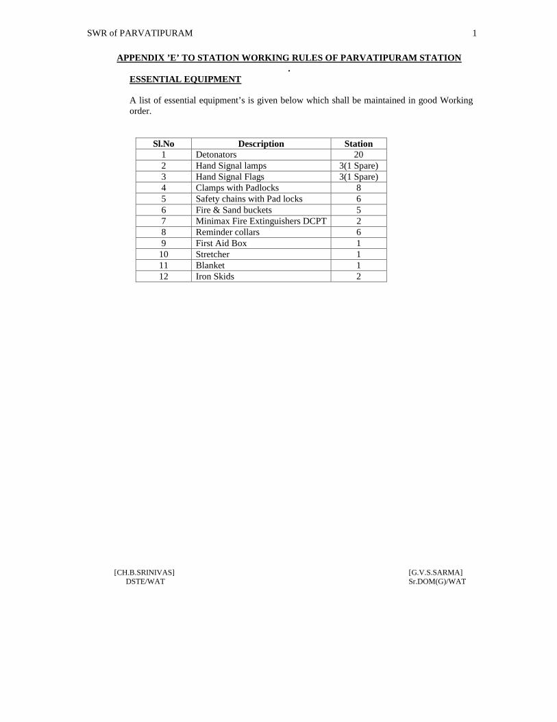
SWR of PARVATIPURAM 1
[CH.B.SRINIVAS] [G.V.S.SARMA]DSTE/WAT Sr.DOM(G)/WAT
APPENDIX ’E’ TO STATION WORKING RULES OF PARVATIPURAM STATION.
ESSENTIAL EQUIPMENT
A list of essential equipment’s is given below which shall be maintained in good Workingorder.
Sl.No Description Station1 Detonators 202 Hand Signal lamps 3(1 Spare)3 Hand Signal Flags 3(1 Spare)4 Clamps with Padlocks 85 Safety chains with Pad locks 66 Fire & Sand buckets 57 Minimax Fire Extinguishers DCPT 28 Reminder collars 69 First Aid Box 1
10 Stretcher 111 Blanket 112 Iron Skids 2

SWR of PARVATIPURAM 1
[CH.B.SRINIVAS] [G.V.S.SARMA]DSTE/WAT Sr.DOM(G)/WAT
APPENDIX “F” TO STATION WORKING RULES OF PARVATIPURAM STATION
RULES FOR WORKING OF DK STATIONS. HALTS IBH AND OUTLYINGSIDINGS.
Parvatipuram town [PVPT] is a halt station between PVP- GMDA. Theresponsibility of making a halt and departure on schedule timings is devolved on the Guardand Loco Pilot of the said trains.