earthquake ground motion
TRANSCRIPT

Course Introduction
Earthquake Ground Motion Nicolas Luco, Ph.D., P.E., Michael Valley, S.E., and C.B. Crouse, P.E., Ph.D. Slide set created by Finley A. Charney, Ph.D., P.E.
Instructional Material Complementing FEMA P-751, Design Examples Earthquake Ground Motions - 1
Topics Covered
• 2008 USGS Uniform Hazard Maps • 2009 NEHRP Provisions Maps • ASCE 7-10 Seismic Maps • Determination of Ground Motion Values • Horizontal Response Spectra • Vertical Response Spectra • Peak Ground Acceleration • Selection and Scaling of Ground Motions
Instructional Material Complementing FEMA P-751, Design Examples Earthquake Ground Motions - 2

Topics Covered
• 2008 USGS Uniform Hazard Maps • 2009 NEHRP Provisions Maps • ASCE 7-10 Seismic Maps • Horizontal Response Spectra • Vertical Response Spectra • Peak Ground Acceleration • Selection and Scaling of Ground Motions
Instructional Material Complementing FEMA P-751, Design Examples Earthquake Ground Motions - 3

2008 USGS Maps
• Probabilistic • Uniform Hazard (e.g. 2% in 50 year probability) • Spectral Contours (T=0, 0.1, 0.2 sec…) • 5 % Damping • Site Class B/C Boundary • Geomean Values
Instructional Material Complementing FEMA P-751, Design Examples Earthquake Ground Motions - 4

Obtaining 2008 Maps from USGS Seismic Hazard Data Website
Instructional Material Complementing FEMA P-751, Design Examples Earthquake Ground Motions - 5
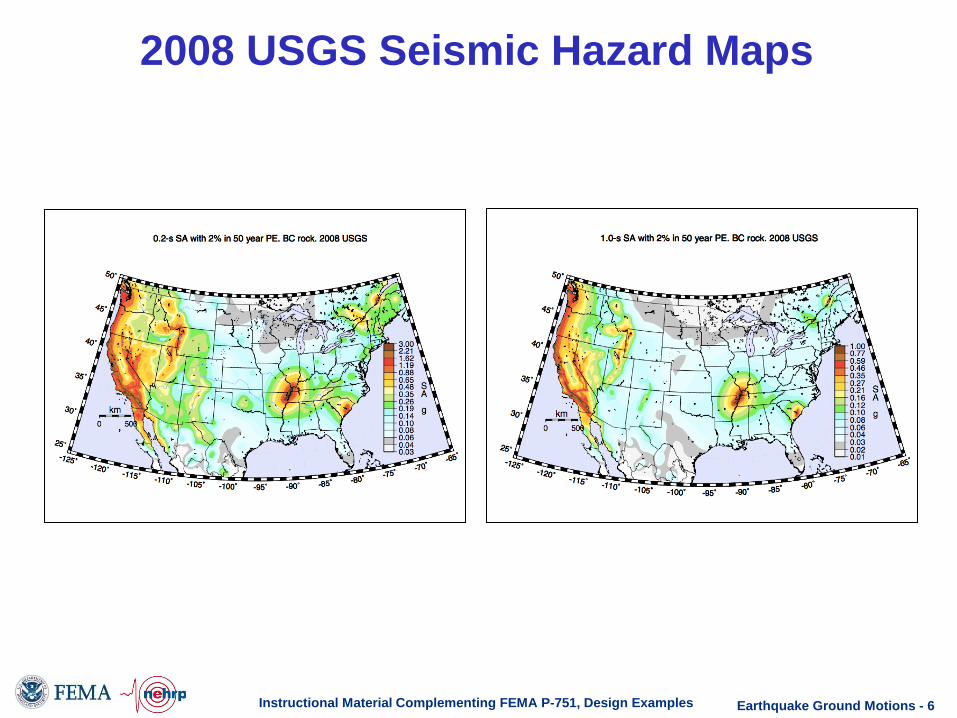
2008 USGS Seismic Hazard Maps
Instructional Material Complementing FEMA P-751, Design Examples Earthquake Ground Motions - 6
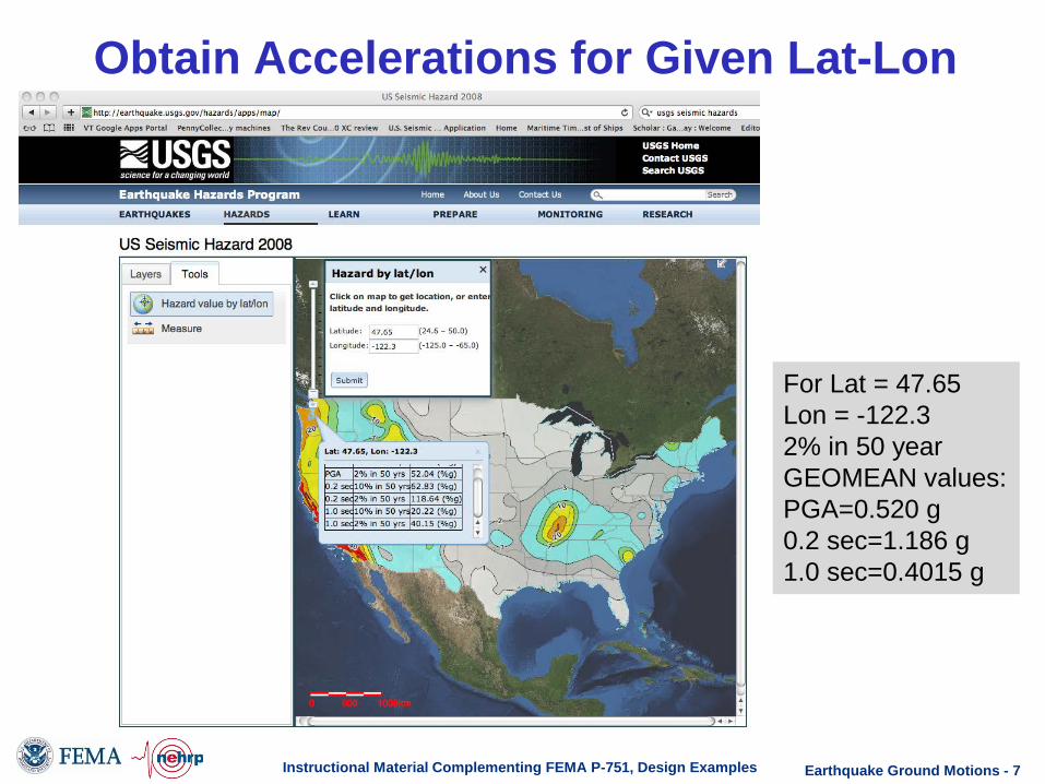
Obtain Accelerations for Given Lat-Lon
Instructional Material Complementing FEMA P-751, Design Examples
For Lat = 47.65 Lon = -122.3 2% in 50 year GEOMEAN values: PGA=0.520 g 0.2 sec=1.186 g 1.0 sec=0.4015 g
Earthquake Ground Motions - 7

2009 NEHRP Maps
• Probabilistic / Deterministic (Separate Maps) • Uniform Risk (Separate Maps) • Spectral Contours (PGA, 0.1, 0.2 sec) • 5 % Damping • Site Class B/C Boundary • Maximum Direction Values
Instructional Material Complementing FEMA P-751, Design Examples Earthquake Ground Motions - 8

2009 NEHRP Probabilistic Maps
Instructional Material Complementing FEMA P-751, Design Examples
T=0.2 Seconds
T=1.0 Seconds
• Probabilistic / Deterministic (Separate Maps) • Uniform Risk (Separate Maps) • Spectral Contours (PGA, 0.1, 0.2 sec) • 5 % Damping • Site Class B/C Boundary • Maximum Direction Values
Earthquake Ground Motions - 9

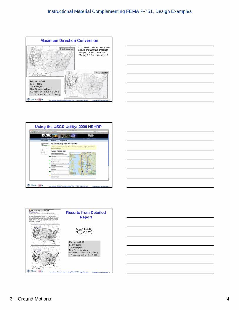
Maximum Direction Conversion
Instructional Material Complementing FEMA P-751, Design Examples
T=0.2 Seconds
T=1.0 Seconds
To convert from USGS Geomean to NEHRP Maximum Direction Multiply 0.2 Sec. values by 1.1 Multiply 1.0 Sec. values by 1.3
For Lat = 47.65 Lon = -122.3 2% in 50 year Max Direction Values: 0.2 sec=1.186 x 1.1 = 1.305 g 1.0 sec=0.4015 x 1.3 = 0.522 g
Earthquake Ground Motions - 10

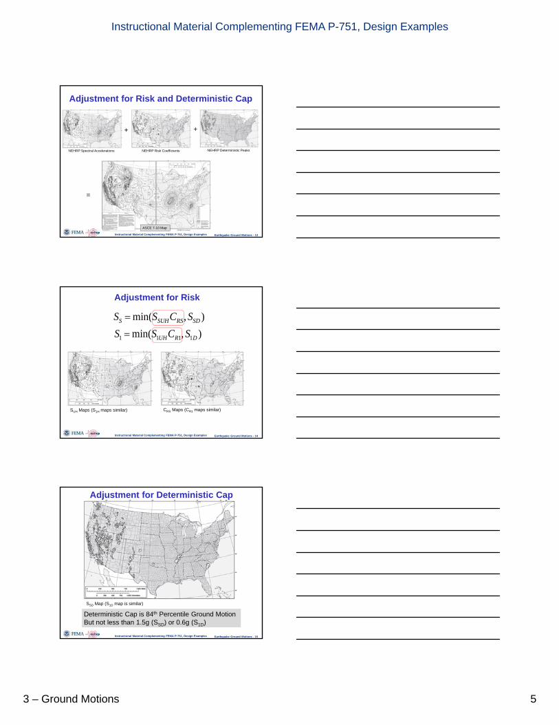
Using the USGS Utility: 2009 NEHRP
Instructional Material Complementing FEMA P-751, Design Examples Earthquake Ground Motions - 11

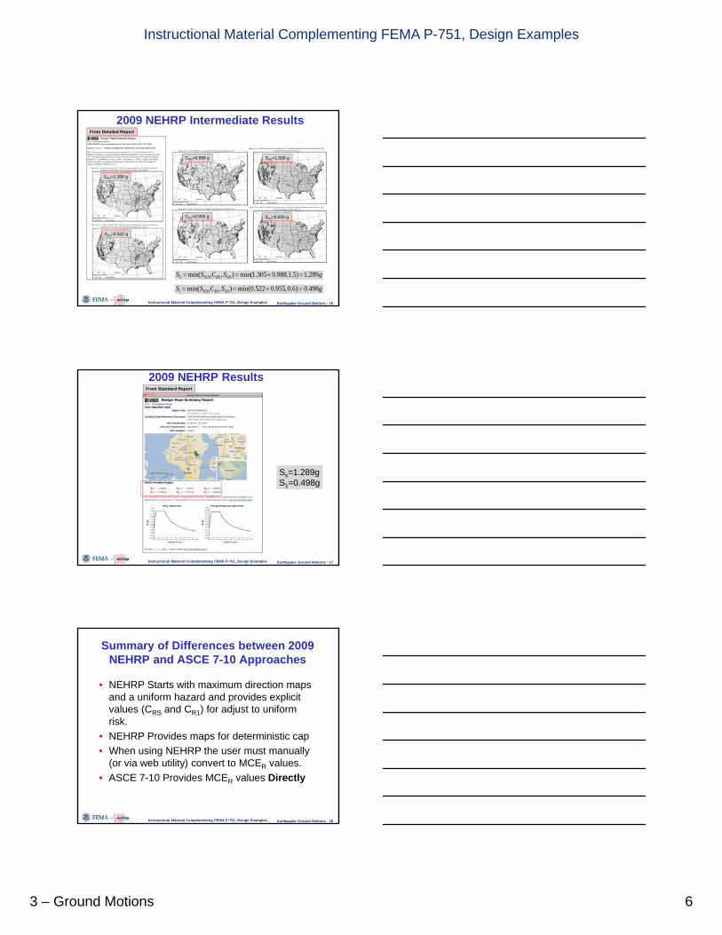
Results from Detailed Report
Instructional Material Complementing FEMA P-751, Design Examples
For Lat = 47.65 Lon = -122.3 2% in 50 year Max Direction Values: 0.2 sec=1.186 x 1.1 = 1.305 g 1.0 sec=0.4015 x 1.3 = 0.522 g
SSUH=1.305g S1UH=0.522g
Earthquake Ground Motions - 12

Adjustment for Risk and Deterministic Cap
Instructional Material Complementing FEMA P-751, Design Examples
NEHRP Spectral Accelerations NEHRP Risk Coefficients NEHRP Deterministic Peaks
ASCE 7-10 Map
+
=
+
Earthquake Ground Motions - 13

Adjustment for Risk
Instructional Material Complementing FEMA P-751, Design Examples
SUH Maps (S1H maps similar) CRS Maps (CR1 maps similar)
Earthquake Ground Motions - 14

Adjustment for Deterministic Cap
Instructional Material Complementing FEMA P-751, Design Examples
SSD Map (S1D map is similar)
Deterministic Cap is 84th Percentile Ground Motion But not less than 1.5g (SSD) or 0.6g (S1D)
Earthquake Ground Motions - 15

2009 NEHRP Intermediate Results
Instructional Material Complementing FEMA P-751, Design Examples
From Detailed Report
SUH=1.305 g
S1H=0.522 g
CRS=0.988 g
CR1=0.955 g
SSD=1.500 g
S1D=0.600 g
Earthquake Ground Motions - 16

2009 NEHRP Results
Instructional Material Complementing FEMA P-751, Design Examples
From Standard Report
Ss=1.289g S1=0.498g
Earthquake Ground Motions - 17

Summary of Differences between 2009 NEHRP and ASCE 7-10 Approaches
• NEHRP Starts with maximum direction maps and a uniform hazard and provides explicit values (CRS and CR1) for adjust to uniform risk.
• NEHRP Provides maps for deterministic cap • When using NEHRP the user must manually
(or via web utility) convert to MCER values. • ASCE 7-10 Provides MCER values Directly
Instructional Material Complementing FEMA P-751, Design Examples Earthquake Ground Motions - 18
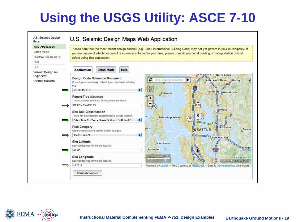
Using the USGS Utility: ASCE 7-10
Instructional Material Complementing FEMA P-751, Design Examples Earthquake Ground Motions - 19

ASCE 7-10 Results
Instructional Material Complementing FEMA P-751, Design Examples
From Standard Report
From Detailed Report
Ss=1.289g S1=0.498g
Earthquake Ground Motions - 20

Adjusting for Site Effects 2009 NEHRP and ASCE 7-10
Instructional Material Complementing FEMA P-751, Design Examples
From Detailed Report
SDS=0.860g SD1=0.433g
Earthquake Ground Motions - 21

Topics Covered
• 2008 USGS Uniform Hazard Maps • 2009 NEHRP Provisions Maps • ASCE 7-10 Seismic Maps • Horizontal Response Spectra • Vertical Response Spectra • Peak Ground Acceleration • Selection and Scaling of Ground Motions
Instructional Material Complementing FEMA P-751, Design Examples Earthquake Ground Motions - 22

Development of Design Spectrum
Instructional Material Complementing FEMA P-751, Design Examples
Constant Acceleration
Constant Velocity
Constant Displacement
Earthquake Ground Motions - 23

Development of Design Spectrum
Instructional Material Complementing FEMA P-751, Design Examples
SDS=0.860g SD1=0.433g
Fig. 22-7 Long Period Transition Maps
TL=6 s (from map)
0.0
0.2
0.4
0.6
0.8
1.0
1.2
0 1 2 3 4 5 6 7 8
Period, T (s)
T0 TS
TL
MCER spectrum
designspectrum
Spec
tral A
ccel
erat
ion,
g
Sa @ T=0= 0.4(SDS)=0.4(0.860)=0.344g
Earthquake Ground Motions - 24

Vertical Response Spectra
• New Chapter 23 of NEHRP Provisions • Not yet incorporated into ASCE 7
Instructional Material Complementing FEMA P-751, Design Examples
Spectrum has Four Braches:
Period, TV, sec.
Sav
1
2
3
4
0.025
0.050
0.150 2.0
1
2
3
4
1
Earthquake Ground Motions - 25

Vertical Response Spectra
Instructional Material Complementing FEMA P-751, Design Examples
Period, TV, sec.
Sav
0.025
0.050
0.150 2.0
For current example SS=1.389g, SDS=0.859g, Site Class D
0.298
0.796
Interpolation gives Cv=1.158 Note: This is the DBE Spectra. Multiply all accelerations by 1.5 to obtain MCE Spectra
0.114
Earthquake Ground Motions - 26

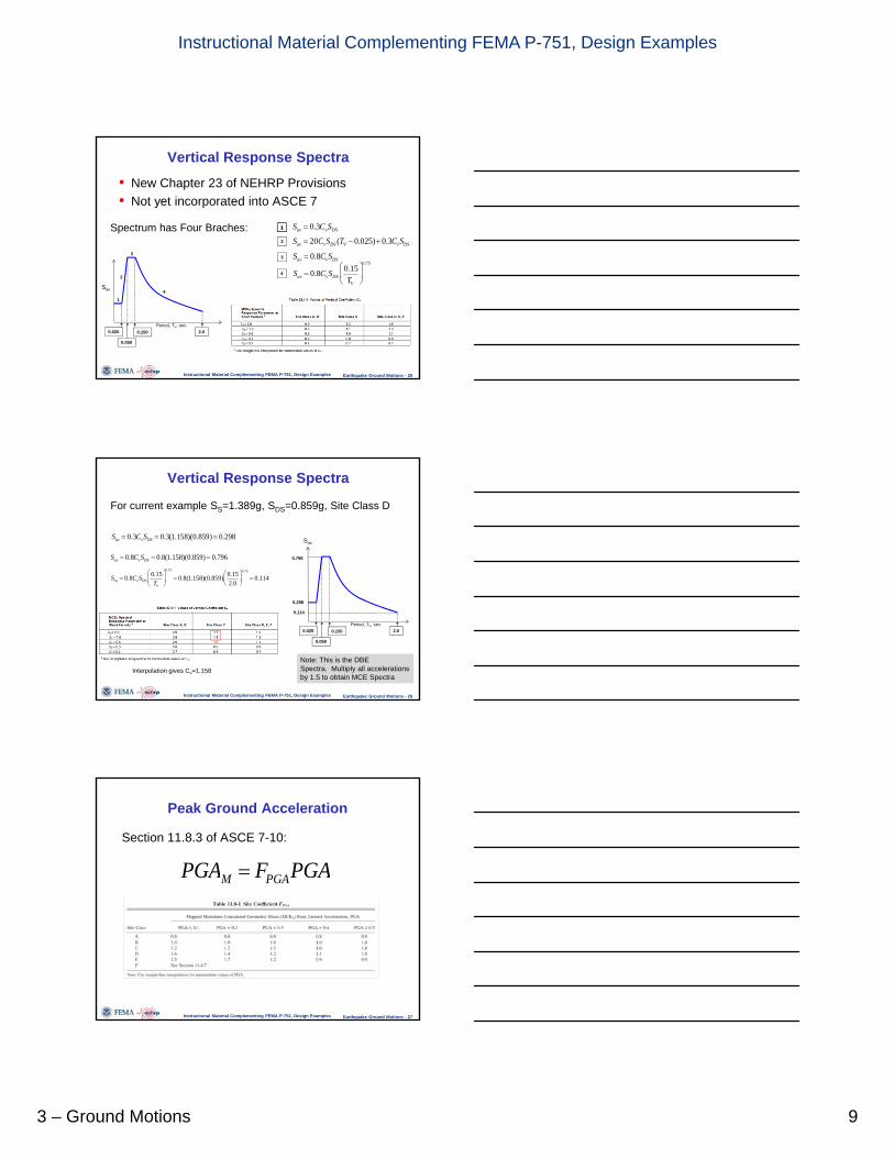
Peak Ground Acceleration
Section 11.8.3 of ASCE 7-10:
Instructional Material Complementing FEMA P-751, Design Examples Earthquake Ground Motions - 27

Peak Ground Acceleration
Instructional Material Complementing FEMA P-751, Design Examples
Results from USGS Design Maps Utility (Detailed Report) for Seattle Location
PGA=0.521 g
FPGA=1.0
Note: This is the MCE PGA. Design PGA (where used) = (2/3) PGAM
Earthquake Ground Motions - 28

Topics Covered
• 2008 USGS Uniform Hazard Maps • 2009 NEHRP Provisions Maps • ASCE 7-10 Seismic Maps • Horizontal Response Spectra • Vertical Response Spectra • Peak Ground Acceleration • Selection and Scaling of Ground Motions
Instructional Material Complementing FEMA P-751, Design Examples Earthquake Ground Motions - 29

Selection and Scaling of Ground Motions • Selection and Scaling procedures are Provided in
Chapter 16 of ASCE 7-10: Response History Analysis
• Chapter 16 is usually used in association with nonlinear analysis of special structures or structures that do not conform to certain requirements (e.g. height limitations) in ASCE 7-10.
• This example will demonstrate procedure for a site in Seattle, Washington.
• Additional discussion of ground motion scaling and use in linear and nonlinear response history analysis is provided in Chapter 4 of P-751, Structural Analysis.
Instructional Material Complementing FEMA P-751, Design Examples Earthquake Ground Motions - 30

Ground Motion Nomenclature
• An “Event” refers to a given historical earthquake, such as the 1989 Loma Prieta California Earthquake
• A “Record” refers to the recorded ground acceleration histories at a particular recording station, such as the Saratoga-Aloha Ave. recording of the Loma Prieta event.
• Each record has (usually) three “Components” consisting of two (usually) orthogonal components and one vertical component. The horizontal components are often, but not always, oriented in N-S and E-W directions. In some cases fault-normal and fault-parallel values are provided. Records can be transformed to any direction (e.g. N-S and E-W recordings can be transformed to fault-normal and fault-parallel given the orientation of the fault.
• A “Suite” of ground motions consist of three or more records.
Instructional Material Complementing FEMA P-751, Design Examples Earthquake Ground Motions - 31

Location of Site
Instructional Material Complementing FEMA P-751, Design Examples Earthquake Ground Motions - 32

Selection of Appropriate Records
Instructional Material Complementing FEMA P-751, Design Examples
• Select from records of events having magnitude, fault distance, and source mechanisms that control the maximum considered earthquake (MCE)
• Pertinent information can be obtained from “Deaggregtion” of the seismic hazard
Earthquake Ground Motions - 33

Deaggreagtion of Hazard (2.0 sec Accel)
Instructional Material Complementing FEMA P-751, Design Examples
Distant large magnitude records
Closer lower magnitude records
Earthquake Ground Motions - 34

Deaggregation of Hazard (2.0 sec Accel)
Instructional Material Complementing FEMA P-751, Design Examples
Distant large magnitude records
Closer lower magnitude records
Earthquake Ground Motions - 35

Instructional Material Complementing FEMA P-751, Design Examples
Deaggreagtion of Hazard (0.2 sec Accel)
Earthquake Ground Motions - 36
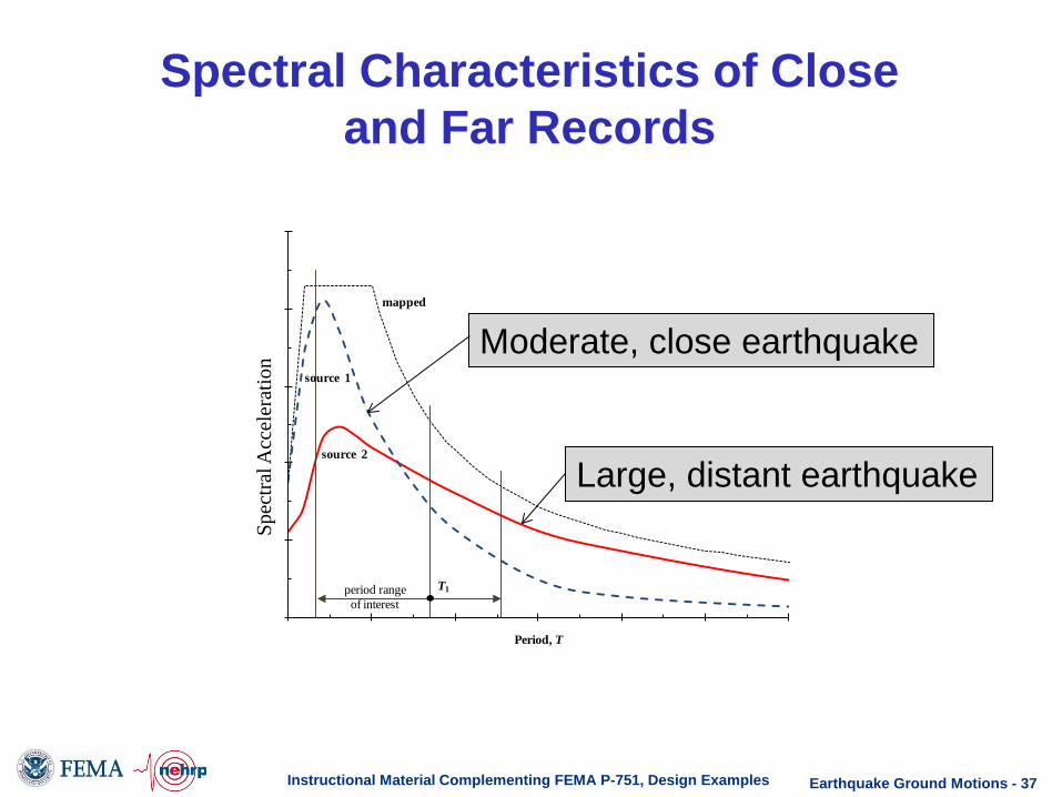
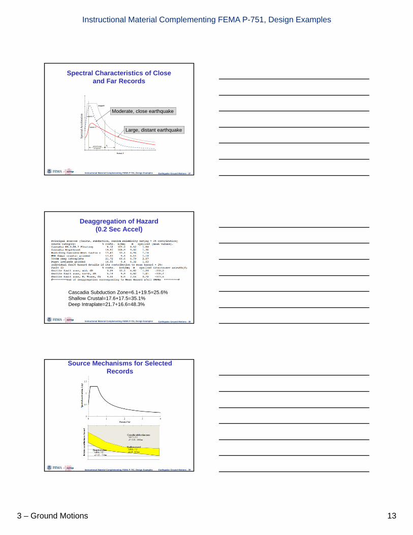
Spectral Characteristics of Close and Far Records
Instructional Material Complementing FEMA P-751, Design Examples
period rangeof interest
T1
Period, T
mapped
source 1
source 2
Large, distant earthquake
Moderate, close earthquake
Spec
tral A
ccel
erat
ion
Earthquake Ground Motions - 37
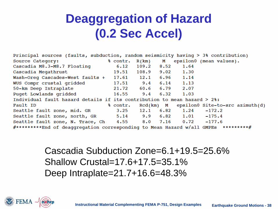
Deaggregation of Hazard (0.2 Sec Accel)
Instructional Material Complementing FEMA P-751, Design Examples
Cascadia Subduction Zone=6.1+19.5=25.6% Shallow Crustal=17.6+17.5=35.1% Deep Intraplate=21.7+16.6=48.3%
Earthquake Ground Motions - 38

Source Mechanisms for Selected Records
Instructional Material Complementing FEMA P-751, Design Examples
25.6%
35.1%
48.3%
T=0.2s
Earthquake Ground Motions - 39

Scaling Requirements • 2D Analysis: The ground motions shall be
scaled such that the average of the 5% damped response spectra is not less than the design spectrum over the period range 0.2T to 1.5T.
• 3D Analysis: The ground motions shall be scaled such that the average of the SRSS spectra from all horizontal component pairs does not fall below the design spectrum over the period range 0.2T to 1.5T.
• At sites within 5 km of the active fault each pair of components shall be rotated to fault-normal and fault-parallel directions and shall be scaled such that the fault normal dominant component is not less than the MCER design spectrum over the period range 0.2 to 1.5T.
Instructional Material Complementing FEMA P-751, Design Examples Earthquake Ground Motions - 40

Ground Motion Scale Factors for 3D Analysis
Instructional Material Complementing FEMA P-751, Design Examples Earthquake Ground Motions - 41

Components of the Northridge Earthquake
Instructional Material Complementing FEMA P-751, Design Examples Earthquake Ground Motions - 42

Ground Motion Spectra
Instructional Material Complementing FEMA P-751, Design Examples
All Records, Unscaled All Records, Scaled to MCE
0.2T=0.46s 1.0T=2.3s 1.5T=3.45s
Earthquake Ground Motions - 43

Response Spectra for Two Selected Scaled Motions
Instructional Material Complementing FEMA P-751, Design Examples
1989 Loma Prieta 1999 Duzce, Turkey
Earthquake Ground Motions - 44

SRSS Scaled Spectra and MCE Spectrum
Instructional Material Complementing FEMA P-751, Design Examples
0.2T=0.46s 1.0T=2.3s
1.5T=3.45s
Earthquake Ground Motions - 45

Scaled Records and DBE Spectrum
Instructional Material Complementing FEMA P-751, Design Examples
0.2T=0.46s 1.0T=2.3s
1.5T=3.46s
Earthquake Ground Motions - 46

Alternate Scaling
Instructional Material Complementing FEMA P-751, Design Examples
Step 1: SRSS Spectra scaled to match target at T=2.3 sec. Step 2: Rescale to conform with requirements over range 0.2T to 1.5 T.
0.2T=0.46s 1.0T=2.3s
1.5T=3.46s
Earthquake Ground Motions - 47

Questions
Instructional Material Complementing FEMA P-751, Design Examples Earthquake Ground Motions - 48

This topic covers Chapter 3 of FEMA P-751, Earthquake Ground Motion. The chapter is presented in two parts, the first being the theoretical basis of the 2008 USGS, the maps in 2009 NEHRP, and the maps in ASCE 7-10. The second part presents some examples for determining ground motion values for a site in Seattle, Washington. This slide sets is a based primarily on the examples. Note that most of the examples use various web-based utilities. It would be valuable for the instructor to have access to the internet so that the applications can be demonstrated live.
Earthquake Ground Motions - 1

This slide presents a list of the topics covered.
Earthquake Ground Motions - 2

This slide presents a list of the first several topics covered.
Earthquake Ground Motions - 3

The maps in ASCE 7 and 2009 NEHRP are derived from the 2008 USGS maps. The USGS maps are purely probabilistic, represent a uniform hazard, and are based on geomean spectral values. The geomean is the square root of the product of the spectral values for the two components, at a particular period. The 2009 maps are split into three parts: Uniform hazard maps that have been converted to maximum direction ground motion, separate maps which provide coefficients to convert to uniform risk, and additional maps provide deterministic caps. This information must be combined to obtain the values of Ss and S1 that are provided directly by ASCE 7-10.
Earthquake Ground Motions - 4

This slide shows a screen captured from a web site developed by USGS. In this instance the site was used to provide maps for the conterminous U.S. for a 2% in 50 year probability of occurrence. Maps for 0.2 second and 1.0 second periods are specified. Maps are then downloaded as PDF files or Postscript files.
Earthquake Ground Motions - 5

PDF files of the two requested maps are shown on this slide. Note that the maps are not particularly useful from a design perspective, but do show in some detail the distribution of shaking hazard across the U.S. In the western U.S. and certain areas in the central and eastern U.S. the ground shaking can be violent, with peak horizontal accelerations as high as 1.0 g. Peak ground acceleration is approximately 0.4 times the 0.2 second spectral acceleration. USGS also provide peak ground acceleration maps if needed.
Earthquake Ground Motions - 6

This slide a screen capture for a USGS utility that provides geomean spectral acceleration by Longitude and Latitude. The given location is in Seattle, Washington. These values provided are purely probabilistic, and are based on a 2% in 50 year seismic hazard. Note that longitude must be entered as a negative number because Seattle is west of the prime meridian.
Earthquake Ground Motions - 7

The 2009 NEHRP provides three sets of maps that are used to provide design values. The first set is a based on a uniform hazard, but has been converted from geomean to maximum direction by use of a simple approximation. The second set of maps provide risk coefficients that are used to convert the maximum direction uniform hazard values to uniform risk values. The final set of maps is used to provide a “deterministic cap” on the probabilistic values where the probabilistic values are greater than the deterministic values.
Earthquake Ground Motions - 8

This slide shows the 2009 NEHRP Uniform Hazard maps which are based on maximum direction motions without a probabilistic cap. Maps are shown are for a 2% in 50 year hazard and for spectral accelerations at periods of 0.2 seconds and 1.0 seconds.
Earthquake Ground Motions - 9

The maps that are shown on this page are the 2009 NEHRP Uniform Hazard Maximum Direction maps. These are obtained by multiplying values on the corresponding 2008 BSSC 0.2 second spectral values by 1.1, and the 2008 USGS 1.0 second spectral values by 1.3. This is an approximation to the maximum direction values.
Earthquake Ground Motions - 10

The USGS Utility can be used to obtain values from the 2009 NEHRP Maps. This slide shows a screen capture of the U.S. Seismic Design Maps Web Application, with the Seattle ordinates of 47.65 Lat and -122.3 Lon keyed in.
Earthquake Ground Motions - 11
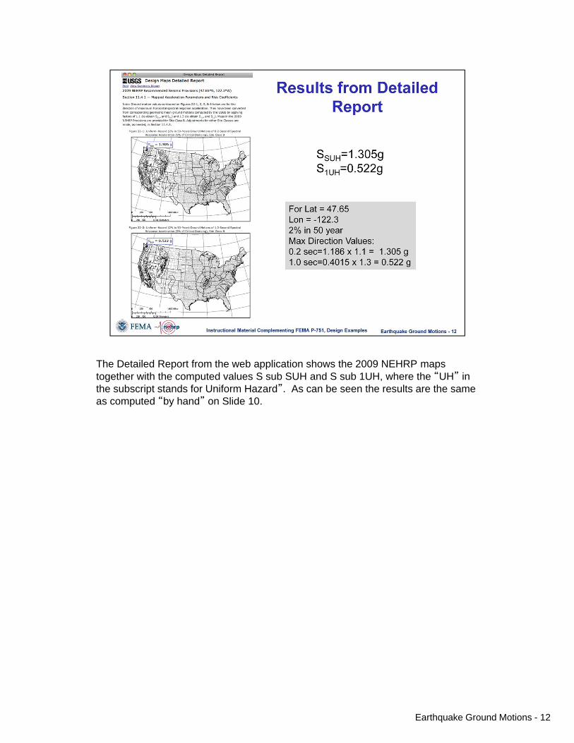
The Detailed Report from the web application shows the 2009 NEHRP maps together with the computed values S sub SUH and S sub 1UH, where the “UH” in the subscript stands for Uniform Hazard”. As can be seen the results are the same as computed “by hand” on Slide 10.
Earthquake Ground Motions - 12

The next step to obtain the ASCE 7 values is to adjust for Uniform Risk by multiplying the Uniform Hazard values by Risk Coefficients. There is one map for 0.2 sec Risk Coefficients, and one Map for 1.0 sec Risk Coefficients.
Earthquake Ground Motions - 13

Before the final ASCE 7-10 mapped values can be determined, it is necessary to make sure the probabilistic Uniform Risk values do not exceed the deterministic cap values. 2009 NEHRP Provides the maps of the deterministic caps.
Earthquake Ground Motions - 14

This slide shows the deterministic contours for the 0.2 second acceleration.
Earthquake Ground Motions - 15

Finally, the values of S sub S and S sub 1 can be found. Values computed by hand are shown.
Earthquake Ground Motions - 16

The values computed by the USGS Application are the same as those computed by hand, as shown on this screen capture from the detailed report.
Earthquake Ground Motions - 17

A summary of the differences between the 2009 NEHRP and the ASCE 7-10 Maps is provided on this slide.
Earthquake Ground Motions - 18

The USGS Utility can be used to determine the ASCE 7 Design Values (S sub s and S sub 1) directly. The slide shows a screen capture of the utility with the pertinent information keyed in for the Seattle location. Note again the negative value entered for longitude.
Earthquake Ground Motions - 19

The results from the USGS Utility are provided by the screen captures shown on this slide.
Earthquake Ground Motions - 20

The USGS Web application also provides the interpolated values of the site coefficients F sub a and F sub v. Using these values, S sub MS and Sub sub M1 are obtained, where the “M” stands for Maximum Considered Earthquake. Dividing these values by 1.5 provides the Design values S sub DS and S sub D1.
Earthquake Ground Motions - 21

This slide presents a list of the next three topics covered.
Earthquake Ground Motions - 22
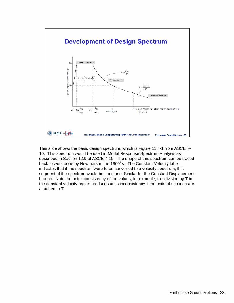
This slide shows the basic design spectrum, which is Figure 11.4-1 from ASCE 7-10. This spectrum would be used in Modal Response Spectrum Analysis as described in Section 12.9 of ASCE 7-10. The shape of this spectrum can be traced back to work done by Newmark in the 1960’s. The Constant Velocity label indicates that if the spectrum were to be converted to a velocity spectrum, this segment of the spectrum would be constant. Similar for the Constant Displacement branch. Note the unit inconsistency of the values; for example, the division by T in the constant velocity region produces units inconsistency if the units of seconds are attached to T.
Earthquake Ground Motions - 23

This slide shows the calculation of the intermediate values needed to construct the design spectrum. Also shown is the long period transition map which provides the periods at which the constant displacement branch of the spectrum governs. For the location in Seattle, T sub L is 6 seconds. This represents (approximately) a building that is 30 to 40 stories in height, and is thus the spectrum beyond T sub L is not likely to control for most buildings.
Earthquake Ground Motions - 24

The 2009 NEHRP Provisions provide a means for computing a vertical design spectrum. The spectrum contains four branches, as shown. Note that the period shown in the plot and used in the calculations is the vertical period of vibration of the structure. For vertical periods beyond 2 seconds (not likely for most buildings) a site specific analysis must be used to determine the vertical spectral values. The procedure for computing the vertical response spectrum is not adopted for use in ASCE 7-10.
Earthquake Ground Motions - 25

This slide shows the computation steps for the vertical acceleration for the Seattle Site.
Earthquake Ground Motions - 26

ASCE 7-10 provides a means to calculate the Peak Ground Acceleration. This values is used in determination of the potential for liquefaction. The PGA values are provided by the Map of Figure 22-7, or by the USGS Utility.
Earthquake Ground Motions - 27

Computation of the MCE level PGA is shown for the Seattle site. The calculation was done using the USGS application, as indicated by the screen capture. Note that the mapped value of PGA, 0.521 g, is the same as provided by the USGS maps, not adjusted for maximum and not adjusted for risk.
Earthquake Ground Motions - 28

This slide presents a list of the topics covered, and indicates that the next topic covered (the last topic) is Ground Motion Selection and Scaling. Selection and Scaling of ground motions is required whenever a response history analysis is to be used.
Earthquake Ground Motions - 29

The slide provides several important points regarding selection and scaling of ground motions.
Earthquake Ground Motions - 30

This slide provides nomenclature used in ground motion selection and scaling.
Earthquake Ground Motions - 31

In the following example we will describe the procedures for selecting a suite of motions for the site in Seattle.
Earthquake Ground Motions - 32

The first bullet is taken directly from Chapter 16 of ASCE 7-10. While there are thousands of recordings available (e.g. from the PEER NGA site), it is often difficult to find a suitable number of records that match the criterion listed. The USGS utility for hazard deaggregation provides information that can be used to detect the appropriate types of ground motions (but not the actual recordings themselves).
Earthquake Ground Motions - 33
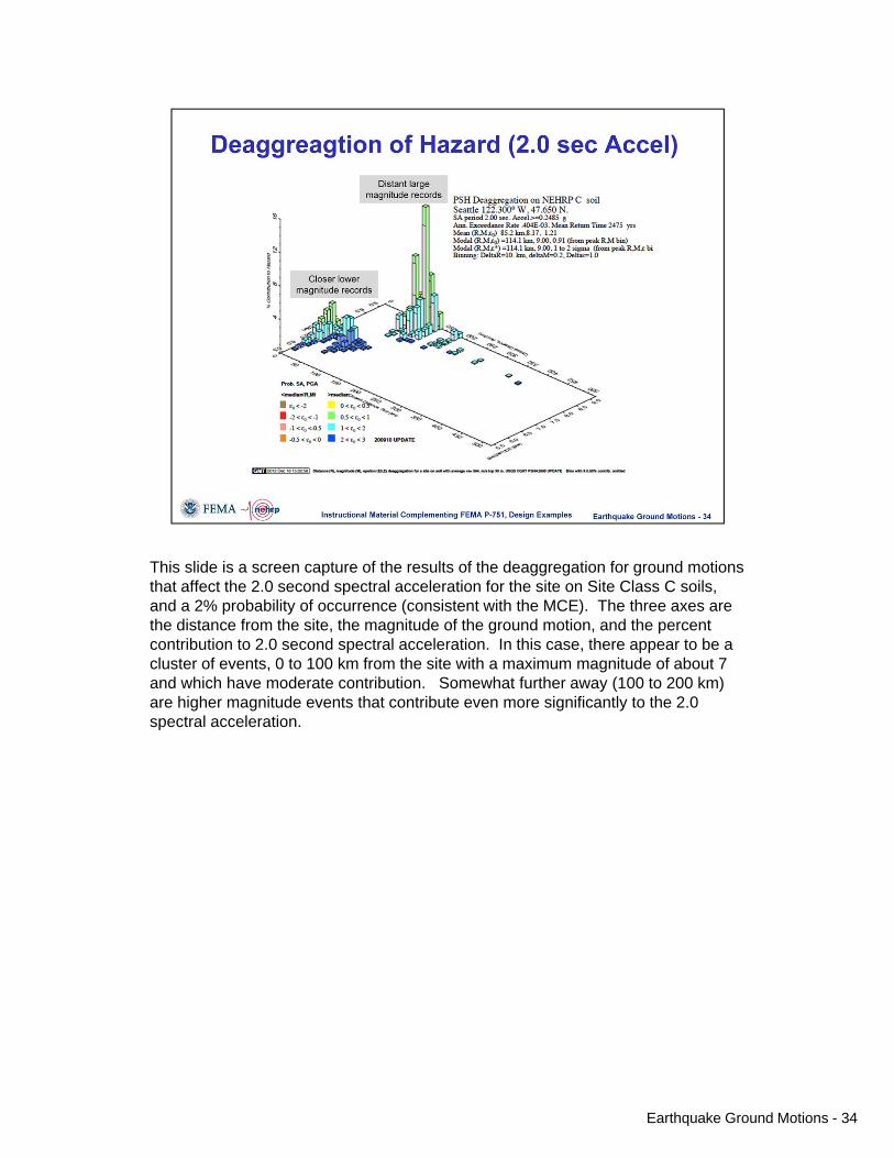
This slide is a screen capture of the results of the deaggregation for ground motions that affect the 2.0 second spectral acceleration for the site on Site Class C soils, and a 2% probability of occurrence (consistent with the MCE). The three axes are the distance from the site, the magnitude of the ground motion, and the percent contribution to 2.0 second spectral acceleration. In this case, there appear to be a cluster of events, 0 to 100 km from the site with a maximum magnitude of about 7 and which have moderate contribution. Somewhat further away (100 to 200 km) are higher magnitude events that contribute even more significantly to the 2.0 spectral acceleration.
Earthquake Ground Motions - 34

This slide shows the 2.0 second deaggregation information on a map of the area surrounding the site.
Earthquake Ground Motions - 35

The same USHS utility can provide deaggregation information at any period. In these screen captures the contribution to the 0.2 second spectral acceleration is shown. Note how the importance of the close-by motion has increased dramatically when compared to the deaggregation for the 2.0 second acceleration.
Earthquake Ground Motions - 36

Similar information is shown on this plot, which shows response spectra for large distant earthquakes, for moderate close-by earthquakes, and the code design spectrum. The moderate, close-by earthquake dominates at lower periods, and the large distant earthquake dominates at the longer periods. The smooth ground motion curves were obtained from ground motion models called “attenuation relationships”.
Earthquake Ground Motions - 37

The deaggregation utility provides detailed information on how different types of earthquake contribute to the hazard. A portion of the the text file that is provided with the deaggregation is shown.
Earthquake Ground Motions - 38
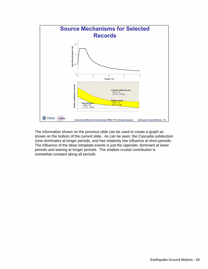
The information shown on the previous slide can be used to create a graph as shown on the bottom of the current slide. As can be seen, the Cascadia subduction zone dominates at longer periods, and has relatively low influence at short periods. The influence of the deep intraplate events is just the opposite; dominant at lower periods and waning at longer periods. The shallow crustal contribution is somewhat constant along all periods.
Earthquake Ground Motions - 39
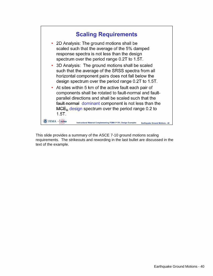
This slide provides a summary of the ASCE 7-10 ground motions scaling requirements. The strikeouts and rewording in the last bullet are discussed in the text of the example.
Earthquake Ground Motions - 40

The table provides seven records that fit the characteristics derived from the deaggregation. As may be seen, the sources types, magnitudes, and distances are consistent with the deaggregation. (Other pertinent information, not shown in the example, is the site class at the recording station. This should be consistent with the site class for the building under consideration). Note that all distances are greater than 5km, so it is not necessary to rotate the components to fault-normal, fault parallel, or to find the dominant component.
Earthquake Ground Motions - 41

These ground motion acceleration histories are fault normal (upper) and fault parallel (lower). The orbit plot (lower right corner of slide) shows that the motions in the two directions are largely out of phase, and that the maximum resultant acceleration occurs at a 45 degree rotation.
Earthquake Ground Motions - 42
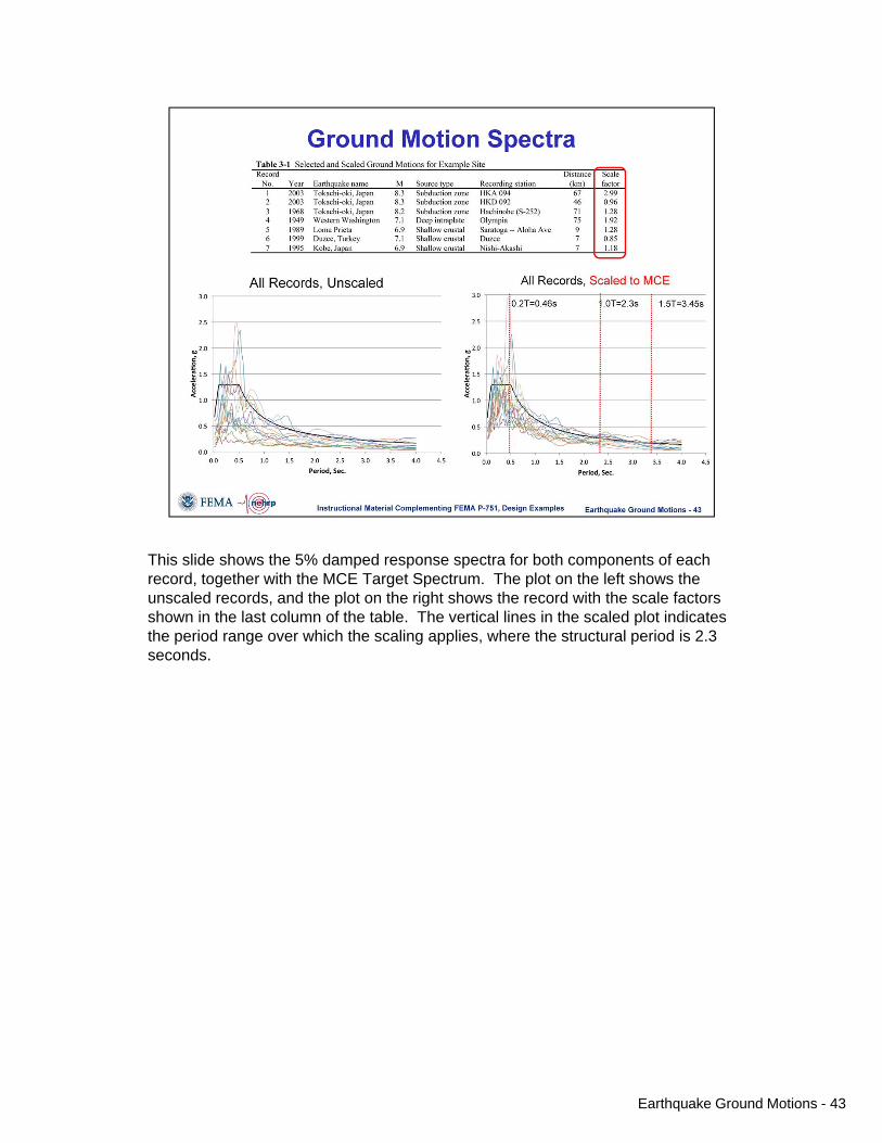
This slide shows the 5% damped response spectra for both components of each record, together with the MCE Target Spectrum. The plot on the left shows the unscaled records, and the plot on the right shows the record with the scale factors shown in the last column of the table. The vertical lines in the scaled plot indicates the period range over which the scaling applies, where the structural period is 2.3 seconds.
Earthquake Ground Motions - 43

This slide shows the response spectra for two of the scaled records. Each individual component is shown, as is the SRSS and the MCE target spectrum. The individual component spectra as well as the SRSS spectra have a shape that is consistent with the target spectrum over the indicated period range.
Earthquake Ground Motions - 44

The plot on this slide shows the scaled SRSS spectra for the seven events, together with the average of the SRSS (heavy red line), and the target MCE spectrum (heavy black line). As can be seen, the Average SRSS falls above the target spectrum over the indicated period range, with the match point at about T=1.0 sec. Note that one of the SRSS spectra (for GM 7) has high amplitude at T=0.5 seconds. Thus, this record will have a larger higher mode influence than will the other records. Note also that the ordinate for GM 1 is nearly twice the ordinate of the design spectrum at the period of 2.3 seconds.
Earthquake Ground Motions - 45

This plot shows the individual MCE scaled components together with the DBE target spectrum. On the average, the MCE scaled records are a good match for the DBE target spectrum, thus little additional scaling would be required if was desired to re-scale for analysis in 2-Dimensions, where the average of the individual component spectra is used instead of the average of the SRSS spectra.
Earthquake Ground Motions - 46

In the Chapter 3 example the method for determining the individual record scale factors was not mentioned. In fact, there are an infinite number of sets of factors that will fit the ASCE 7 criterion. In this slide, an approach is used where the SRSS spectra are first scaled to match the target spectra at the design period (2.3 sec in this example), and then re-scaled such that the average of the SRSS spectra does not fall below the target over the period range 0.2 to 1.5 T. As may be seen, the fit is much better near the target period, but a few of the individual records have relatively low acceleration at the lower periods.
Earthquake Ground Motions - 47

Slide to initiate questions from participants.
Earthquake Ground Motions - 48

Instructional Material Complementing FEMA P-751, Design Examples
3 – Ground Motions 1
Course Introduction
3
Earthquake Ground MotionNicolas Luco, Ph.D., P.E., Michael Valley, S.E.,and C.B. Crouse, P.E., Ph.D.
Slide set created by Finley A. Charney, Ph.D., P.E.
Instructional Material Complementing FEMA P-751, Design Examples Earthquake Ground Motions - 1
Topics Covered
• 2008 USGS Uniform Hazard Maps• 2009 NEHRP Provisions Maps• ASCE 7-10 Seismic Maps• Determination of Ground Motion Values• Horizontal Response Spectra• Vertical Response Spectra• Peak Ground Acceleration• Selection and Scaling of Ground Motions
Instructional Material Complementing FEMA P-751, Design Examples Earthquake Ground Motions - 2
Topics Covered
• 2008 USGS Uniform Hazard Maps• 2009 NEHRP Provisions Maps• ASCE 7-10 Seismic Maps• Horizontal Response Spectra• Vertical Response Spectra• Peak Ground Acceleration• Selection and Scaling of Ground Motions
Instructional Material Complementing FEMA P-751, Design Examples Earthquake Ground Motions - 3

Instructional Material Complementing FEMA P-751, Design Examples
3 – Ground Motions 2
2008 USGS Maps
• Probabilistic • Uniform Hazard (e.g. 2% in 50 year probability)• Spectral Contours (T=0, 0.1, 0.2 sec…)• 5 % Damping• Site Class B/C Boundary• Geomean Values
Instructional Material Complementing FEMA P-751, Design Examples Earthquake Ground Motions - 4
Obtaining 2008 Maps from USGS Seismic Hazard Data Website
Instructional Material Complementing FEMA P-751, Design Examples Earthquake Ground Motions - 5
2008 USGS Seismic Hazard Maps
Instructional Material Complementing FEMA P-751, Design Examples Earthquake Ground Motions - 6

Instructional Material Complementing FEMA P-751, Design Examples
3 – Ground Motions 3
Obtain Accelerations for Given Lat-Lon
Instructional Material Complementing FEMA P-751, Design Examples
For Lat = 47.65Lon = -122.32% in 50 yearGEOMEAN values:PGA=0.520 g0.2 sec=1.186 g1.0 sec=0.4015 g
Earthquake Ground Motions - 7
2009 NEHRP Maps
• Probabilistic / Deterministic (Separate Maps)• Uniform Risk (Separate Maps)• Spectral Contours (PGA, 0.1, 0.2 sec)• 5 % Damping• Site Class B/C Boundary• Maximum Direction Values
Instructional Material Complementing FEMA P-751, Design Examples Earthquake Ground Motions - 8
2009 NEHRP Probabilistic Maps
Instructional Material Complementing FEMA P-751, Design Examples
T=0.2 Seconds
T=1.0 Seconds
• Probabilistic / Deterministic (Separate Maps)• Uniform Risk (Separate Maps)• Spectral Contours (PGA, 0.1, 0.2 sec)• 5 % Damping• Site Class B/C Boundary• Maximum Direction Values
Earthquake Ground Motions - 9
Instructional Material Complementing FEMA P-751, Design Examples
3 – Ground Motions 4
Maximum Direction Conversion
Instructional Material Complementing FEMA P-751, Design Examples
T=0.2 Seconds
T=1.0 Seconds
To convert from USGS Geomeanto NEHRP Maximum DirectionMultiply 0.2 Sec. values by 1.1Multiply 1.0 Sec. values by 1.3
For Lat = 47.65Lon = -122.32% in 50 yearMax Direction Values:0.2 sec=1.186 x 1.1 = 1.305 g1.0 sec=0.4015 x 1.3 = 0.522 g
Earthquake Ground Motions - 10
Using the USGS Utility: 2009 NEHRP
Instructional Material Complementing FEMA P-751, Design Examples Earthquake Ground Motions - 11
Results from Detailed Report
Instructional Material Complementing FEMA P-751, Design Examples
For Lat = 47.65Lon = -122.32% in 50 yearMax Direction Values:0.2 sec=1.186 x 1.1 = 1.305 g1.0 sec=0.4015 x 1.3 = 0.522 g
SSUH=1.305gS1UH=0.522g
Earthquake Ground Motions - 12
Instructional Material Complementing FEMA P-751, Design Examples
3 – Ground Motions 5
Adjustment for Risk and Deterministic Cap
Instructional Material Complementing FEMA P-751, Design Examples
NEHRP Spectral Accelerations NEHRP Risk Coefficients NEHRP Deterministic Peaks
ASCE 7-10 Map
+
=
+
Earthquake Ground Motions - 13
Adjustment for Risk
Instructional Material Complementing FEMA P-751, Design Examples
SS min(SSUHCRS, SSD )S1 min(S1UHCR1, S1D )
SUH Maps (S1H maps similar) CRS Maps (CR1 maps similar)
Earthquake Ground Motions - 14
Adjustment for Deterministic Cap
Instructional Material Complementing FEMA P-751, Design Examples
SSD Map (S1D map is similar)
Deterministic Cap is 84th Percentile Ground MotionBut not less than 1.5g (SSD) or 0.6g (S1D)
Earthquake Ground Motions - 15
Instructional Material Complementing FEMA P-751, Design Examples
3 – Ground Motions 6
2009 NEHRP Intermediate Results
Instructional Material Complementing FEMA P-751, Design Examples
SS min(SSUHCRS, SSD ) min(1.305 0.988,1.5) 1.289g
S1 min(S1UHCR1, S1D ) min(0.522 0.955, 0.6) 0.498g
From Detailed Report
SUH=1.305 g
S1H=0.522 g
CRS=0.988 g
CR1=0.955 g
SSD=1.500 g
S1D=0.600 g
Earthquake Ground Motions - 16
2009 NEHRP Results
Instructional Material Complementing FEMA P-751, Design Examples
From Standard Report
Ss=1.289gS1=0.498g
Earthquake Ground Motions - 17
Summary of Differences between 2009 NEHRP and ASCE 7-10 Approaches
• NEHRP Starts with maximum direction maps and a uniform hazard and provides explicit values (CRS and CR1) for adjust to uniform risk.
• NEHRP Provides maps for deterministic cap• When using NEHRP the user must manually
(or via web utility) convert to MCER values.• ASCE 7-10 Provides MCER values Directly
Instructional Material Complementing FEMA P-751, Design Examples Earthquake Ground Motions - 18

Instructional Material Complementing FEMA P-751, Design Examples
3 – Ground Motions 7
Using the USGS Utility: ASCE 7-10
Instructional Material Complementing FEMA P-751, Design Examples Earthquake Ground Motions - 19
ASCE 7-10 Results
Instructional Material Complementing FEMA P-751, Design Examples
From Standard Report
From Detailed Report
Ss=1.289gS1=0.498g
Earthquake Ground Motions - 20
Adjusting for Site Effects2009 NEHRP and ASCE 7-10
Instructional Material Complementing FEMA P-751, Design Examples
From Detailed Report
SDS=0.860gSD1=0.433g
Earthquake Ground Motions - 21

Instructional Material Complementing FEMA P-751, Design Examples
3 – Ground Motions 8
Topics Covered
• 2008 USGS Uniform Hazard Maps• 2009 NEHRP Provisions Maps• ASCE 7-10 Seismic Maps• Horizontal Response Spectra• Vertical Response Spectra• Peak Ground Acceleration• Selection and Scaling of Ground Motions
Instructional Material Complementing FEMA P-751, Design Examples Earthquake Ground Motions - 22
Development of Design Spectrum
Instructional Material Complementing FEMA P-751, Design Examples
Constant Acceleration
Constant Velocity
Constant Displacement
Earthquake Ground Motions - 23
Development of Design Spectrum
Instructional Material Complementing FEMA P-751, Design Examples
SDS=0.860gSD1=0.433g
Ts SD1
SDS
0.8600.433
0.503 s
Fig. 22-7 Long Period Transition Maps
T0 0.2TS 0.2(0.503) 0.10 s
TL=6 s (from map)
0.0
0.2
0.4
0.6
0.8
1.0
1.2
0 1 2 3 4 5 6 7 8
Period, T (s)
T0 TS
TL
MCER spectrum
designspectrum
Spec
tral A
ccel
erat
ion,
g
Sa @ T=0= 0.4(SDS)=0.4(0.860)=0.344g
Earthquake Ground Motions - 24
Instructional Material Complementing FEMA P-751, Design Examples
3 – Ground Motions 9
Vertical Response Spectra
• New Chapter 23 of NEHRP Provisions• Not yet incorporated into ASCE 7
Instructional Material Complementing FEMA P-751, Design Examples
Spectrum has Four Braches:
Period, TV, sec.
Sav
1
2
3
4
0.025
0.050
0.150 2.0
Sav 0.3CvSDS
Sav 20CvSDS (TV 0.025)0.3CvSDS
Sav 0.8CvSDS
Sav 0.8CvSDS
0.15TV
0.75
1
2
3
4
1
Earthquake Ground Motions - 25
Vertical Response Spectra
Instructional Material Complementing FEMA P-751, Design Examples
Period, TV, sec.
Sav
0.025
0.050
0.150 2.0
Sav 0.3CvSDS 0.3(1.158)(0.859) 0.298
Sav 0.8CvSDS 0.8(1.158)(0.859) 0.796
Sav 0.8CvSDS
0.15TV
0.75
0.8(1.158)(0.859) 0.152.0
0.75
0.114
For current example SS=1.389g, SDS=0.859g, Site Class D
0.298
0.796
Interpolation gives Cv=1.158Note: This is the DBESpectra. Multiply all accelerationsby 1.5 to obtain MCE Spectra
0.114
Earthquake Ground Motions - 26
Peak Ground Acceleration
Section 11.8.3 of ASCE 7-10:
Instructional Material Complementing FEMA P-751, Design Examples
PGAM FPGAPGA
Earthquake Ground Motions - 27

Instructional Material Complementing FEMA P-751, Design Examples
3 – Ground Motions 10
Peak Ground Acceleration
Instructional Material Complementing FEMA P-751, Design Examples
Results from USGS Design Maps Utility(Detailed Report) for Seattle Location
PGA=0.521 g
FPGA=1.0
PGAM FPGAPGA 1.00.521 0.521g
Note: This is the MCE PGA. Design PGA(where used) = (2/3) PGAM
Earthquake Ground Motions - 28
Topics Covered
• 2008 USGS Uniform Hazard Maps• 2009 NEHRP Provisions Maps• ASCE 7-10 Seismic Maps• Horizontal Response Spectra• Vertical Response Spectra• Peak Ground Acceleration• Selection and Scaling of Ground Motions
Instructional Material Complementing FEMA P-751, Design Examples Earthquake Ground Motions - 29
Selection and Scaling of Ground Motions• Selection and Scaling procedures are Provided in
Chapter 16 of ASCE 7-10: Response History Analysis
• Chapter 16 is usually used in association with nonlinear analysis of special structures or structures that do not conform to certain requirements (e.g. height limitations) in ASCE 7-10.
• This example will demonstrate procedure for a site in Seattle, Washington.
• Additional discussion of ground motion scaling and use in linear and nonlinear response history analysis is provided in Chapter 4 of P-751, Structural Analysis.
Instructional Material Complementing FEMA P-751, Design Examples Earthquake Ground Motions - 30

Instructional Material Complementing FEMA P-751, Design Examples
3 – Ground Motions 11
Ground Motion Nomenclature
• An “Event” refers to a given historical earthquake, such as the 1989 Loma Prieta California Earthquake
• A “Record” refers to the recorded ground acceleration histories at a particular recording station, such as the Saratoga-Aloha Ave. recording of the Loma Prieta event.
• Each record has (usually) three “Components” consisting of two (usually) orthogonal components and one vertical component. The horizontal components are often, but not always, oriented in N-S and E-W directions. In some cases fault-normal and fault-parallel values are provided. Records can be transformed to any direction (e.g. N-S and E-W recordings can be transformed to fault-normal and fault-parallel given the orientation of the fault.
• A “Suite” of ground motions consist of three or more records.
Instructional Material Complementing FEMA P-751, Design Examples Earthquake Ground Motions - 31
Location of Site
Instructional Material Complementing FEMA P-751, Design Examples Earthquake Ground Motions - 32
Selection of Appropriate Records
Instructional Material Complementing FEMA P-751, Design Examples
• Select from records of events having magnitude,fault distance, and source mechanisms that controlthe maximum considered earthquake (MCE)
• Pertinent information can be obtained from “Deaggregtion” of the seismic hazard
Earthquake Ground Motions - 33

Instructional Material Complementing FEMA P-751, Design Examples
3 – Ground Motions 12
Deaggreagtion of Hazard (2.0 sec Accel)
Instructional Material Complementing FEMA P-751, Design Examples
Distant largemagnitude records
Closer lowermagnitude records
Earthquake Ground Motions - 34
Deaggregation of Hazard (2.0 sec Accel)
Instructional Material Complementing FEMA P-751, Design Examples
Distant largemagnitude records
Closer lowermagnitude records
Earthquake Ground Motions - 35
Instructional Material Complementing FEMA P-751, Design Examples
Deaggreagtion of Hazard (0.2 sec Accel)
Earthquake Ground Motions - 36
Instructional Material Complementing FEMA P-751, Design Examples
3 – Ground Motions 13
Spectral Characteristics of Closeand Far Records
Instructional Material Complementing FEMA P-751, Design Examples
period rangeof interest
T1
Period, T
mapped
source 1
source 2
Large, distant earthquake
Moderate, close earthquake
Spec
tral A
ccel
erat
ion
Earthquake Ground Motions - 37
Deaggregation of Hazard(0.2 Sec Accel)
Instructional Material Complementing FEMA P-751, Design Examples
Cascadia Subduction Zone=6.1+19.5=25.6%Shallow Crustal=17.6+17.5=35.1%Deep Intraplate=21.7+16.6=48.3%
Earthquake Ground Motions - 38
Source Mechanisms for Selected Records
Instructional Material Complementing FEMA P-751, Design Examples
25.6%
35.1%
48.3%
T=0.2s
Earthquake Ground Motions - 39

Instructional Material Complementing FEMA P-751, Design Examples
3 – Ground Motions 14
Scaling Requirements• 2D Analysis: The ground motions shall be
scaled such that the average of the 5% damped response spectra is not less than the design spectrum over the period range 0.2T to 1.5T.
• 3D Analysis: The ground motions shall be scaled such that the average of the SRSS spectra from all horizontal component pairs does not fall below the design spectrum over the period range 0.2T to 1.5T.
• At sites within 5 km of the active fault each pair of components shall be rotated to fault-normal and fault-parallel directions and shall be scaled such that the fault normal dominant component is not less than the MCER design spectrum over the period range 0.2 to 1.5T.
Instructional Material Complementing FEMA P-751, Design Examples Earthquake Ground Motions - 40
Ground Motion Scale Factors for 3D Analysis
Instructional Material Complementing FEMA P-751, Design Examples
Table 3-1 Selected and Scaled Ground Motions for Example Site Record
No. Year Earthquake name M Source type Recording station Distance
(km) 1 2003 Tokachi-oki, Japan 8.3 Subduction zone HKA 094 67 2 2003 Tokachi-oki, Japan 8.3 Subduction zone HKD 092 46 3 1968 Tokachi-oki, Japan 8.2 Subduction zone Hachinohe (S-252) 71 4 1949 Western Washington 7.1 Deep intraplate Olympia 75 5 1989 Loma Prieta 6.9 Shallow crustal Saratoga -- Aloha Ave 9 6 1999 Duzce, Turkey 7.1 Shallow crustal Duzce 7 7 1995 Kobe, Japan 6.9 Shallow crustal Nishi-Akashi 7
Earthquake Ground Motions - 41
Components of the Northridge Earthquake
Instructional Material Complementing FEMA P-751, Design Examples Earthquake Ground Motions - 42

Instructional Material Complementing FEMA P-751, Design Examples
3 – Ground Motions 15
Ground Motion Spectra
Instructional Material Complementing FEMA P-751, Design Examples
All Records, Unscaled All Records, Scaled to MCE
Table 3-1 Selected and Scaled Ground Motions for Example Site Record
No. Year Earthquake name M Source type Recording station Distance
(km) Scale factor
1 2003 Tokachi-oki, Japan 8.3 Subduction zone HKA 094 67 2.99 2 2003 Tokachi-oki, Japan 8.3 Subduction zone HKD 092 46 0.96 3 1968 Tokachi-oki, Japan 8.2 Subduction zone Hachinohe (S-252) 71 1.28 4 1949 Western Washington 7.1 Deep intraplate Olympia 75 1.92 5 1989 Loma Prieta 6.9 Shallow crustal Saratoga -- Aloha Ave 9 1.28 6 1999 Duzce, Turkey 7.1 Shallow crustal Duzce 7 0.85 7 1995 Kobe, Japan 6.9 Shallow crustal Nishi-Akashi 7 1.18
0.2T=0.46s 1.0T=2.3s 1.5T=3.45s
Earthquake Ground Motions - 43
Response Spectra for Two SelectedScaled Motions
Instructional Material Complementing FEMA P-751, Design Examples
1989 Loma Prieta 1999 Duzce, Turkey
Earthquake Ground Motions - 44
SRSS Scaled Spectra and MCE Spectrum
Instructional Material Complementing FEMA P-751, Design Examples
0.2T=0.46s 1.0T=2.3s
1.5T=3.45s
Earthquake Ground Motions - 45

Instructional Material Complementing FEMA P-751, Design Examples
3 – Ground Motions 16
Scaled Records and DBE Spectrum
Instructional Material Complementing FEMA P-751, Design Examples
0.2T=0.46s 1.0T=2.3s
1.5T=3.46s
Earthquake Ground Motions - 46
Alternate Scaling
Instructional Material Complementing FEMA P-751, Design Examples
Step 1:SRSS Spectra scaledto match target at T=2.3 sec.Step 2:Rescale to conform with requirements over range 0.2T to1.5 T.
0.2T=0.46s 1.0T=2.3s
1.5T=3.46s
Earthquake Ground Motions - 47
Questions
Instructional Material Complementing FEMA P-751, Design Examples Earthquake Ground Motions - 48