eaf – technology and processsteelfurnaceindia.com/pdf/venugopalan__compatibility_mode_.pdf · eaf...
TRANSCRIPT
EAF – Technology and process
In the last 100 years,the EAF technology has evolved to meet the demands of higher productivity, improved quality of product and flexibility of metallic inputs.
The product mix of modern EAF encompasses all steel grades with an optimised charge mix.
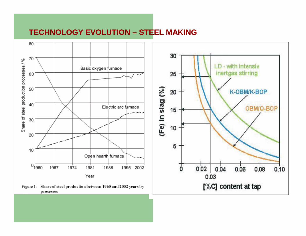
TECHNOLOGY EVOLUTION TECHNOLOGY EVOLUTION –– STEEL MAKINGSTEEL MAKING
Steel making Technology - EAF
EAF is widely used in USA. The capital cost is lower as compared to BOF (also known as LD).
EAF process uses predominantly scrap. DRI is an alternate iron ore bearing material, which is used when the scrap is not available.
A new process, which is known as ‘CONARC’ has been developed by SMS- DEMAG. It employs Hot metal, Scrap and DRI to different proportions as per their availability
Latent needs from customers
Clean steel – Slag free tapping. Low tramp elements in steel – Cu +Sn+Cr < .10%. Phosphorus < 100 ppm ( .01%) Sulphur < 100 ppm ( .010% max) Nitrogen < 50 ppm Dissolved oxygen < 5ppm. Low hydrogen < 2 ppm for some special grades. Close control on chemical composition for steel applications
involving heat treatment and wire drawing Inclusion morphology – Non deformable inclusions to be kept
low for deep drawing of steel

Plan and section of EAF
Steel making Technology - BOF
Does not require external heat, as the process utilizes the heat generated by the exothermic reactions during melting operation.
Hot metal and Scrap are used for melting. Oxygen is blown through a multi hole lance to carry out the refining operation.
Modern converters, have tuyeres at the bottom through which Argon or Nitrogen gas is purged.
Bottom purging leads to uniformity of bath wrt composition and temperature & establishes equilibrium between the slag and the metal. Phosphorous removal is enhanced.
EAF steel making - Advantages
Due to slag free tapping from EAF, clean and high quality steels are produced.
Low phosphorus steels ( P % < .012%) can be consistently produced.
Plant returns can be consumed. Flexibility wrt. Raw materials Low capital cost as compared to a BOF
based facility.

Eccentric bottom tapping – Key to produce SBQ steels.
EBT device facilitates slag free tapping. 10% of the heat weight is always retained in the EAF
after tapping the required heat size. Compact tapping stream minimises Nitrogen pick up. The tap hole wears out after 80 to 90 heats and the
is repaired by inserting a pipe /refractory mix. The tap tube is changed after every 160 to 180 heats
and this takes around 2 hours.
Evolution of EAF technology
AC furnaces require stable electrical grids ( network of with higher fault MVA.
DC furnaces were developed in the 80’s to operate in weak electrical grids. The AC power is converted to DC utilising rectifiers.
The power input in DC furnaces is limited by the electrode diameter ( 800 mm – 140 KA). The higher size of electrodes are expensive.
Twin cathode DC furnaces have been developed to increase power input in DC Electric arc furnaces.
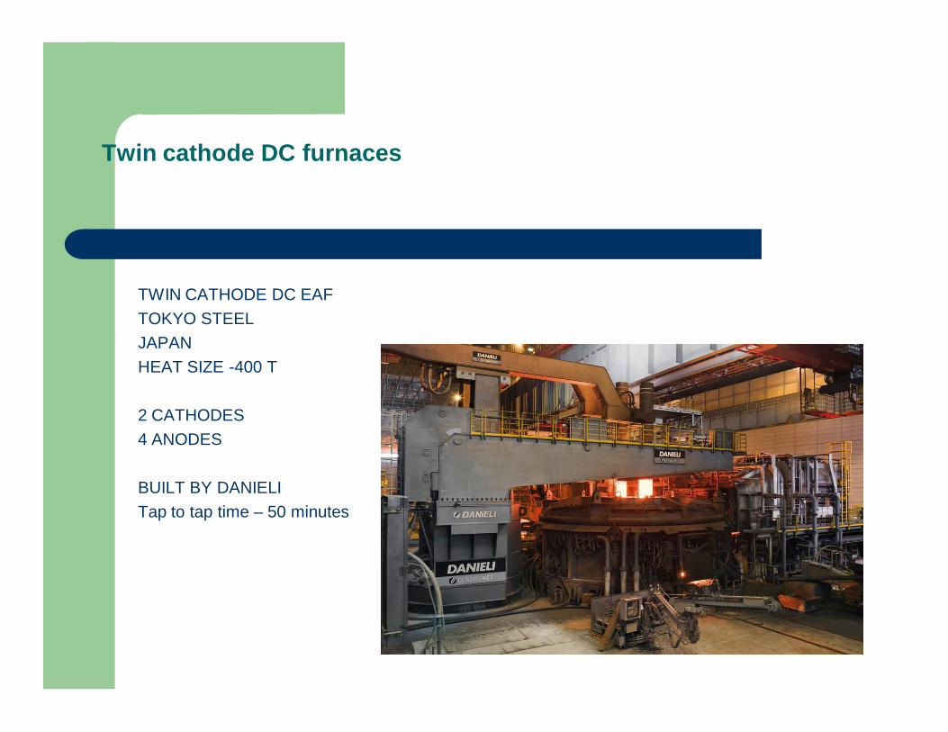
Twin cathode DC furnaces
TWIN CATHODE DC EAFTOKYO STEELJAPANHEAT SIZE -400 T
2 CATHODES4 ANODES
BUILT BY DANIELITap to tap time – 50 minutes
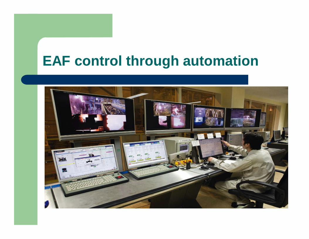
EAF control through automation
Twin cathode DC furnaces
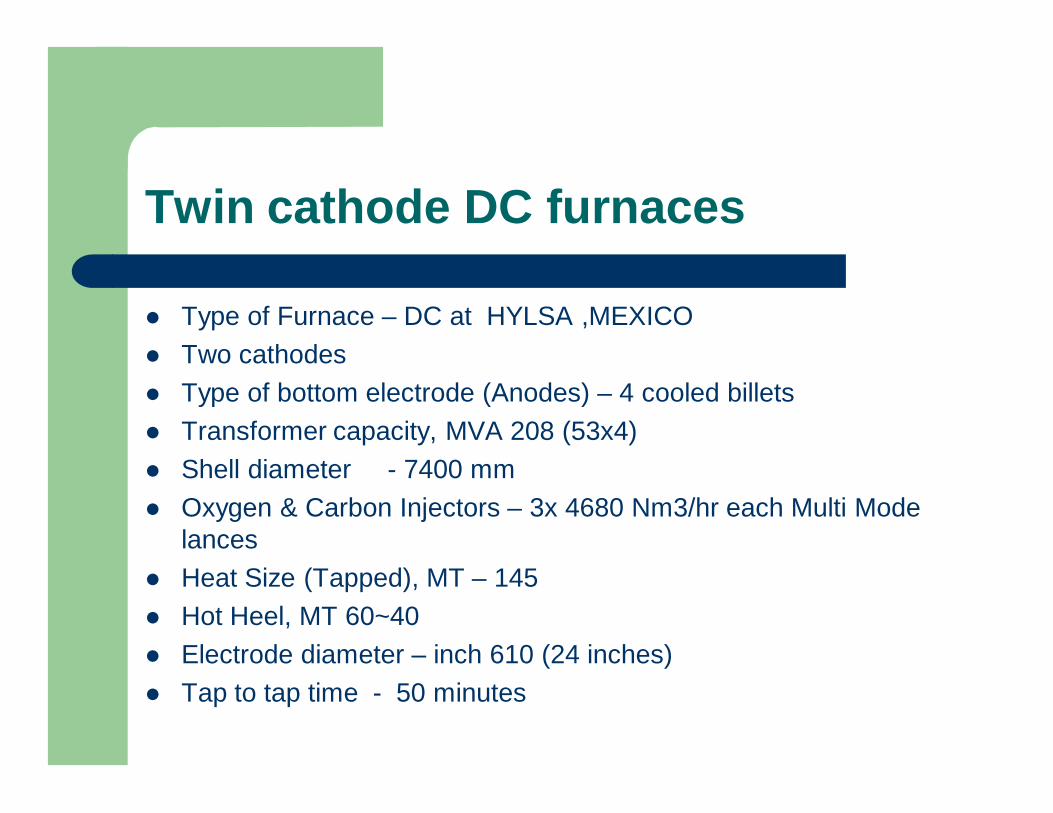
Type of Furnace – DC at HYLSA ,MEXICO Two cathodes Type of bottom electrode (Anodes) – 4 cooled billets Transformer capacity, MVA 208 (53x4) Shell diameter - 7400 mm Oxygen & Carbon Injectors – 3x 4680 Nm3/hr each Multi Mode
lances Heat Size (Tapped), MT – 145 Hot Heel, MT 60~40 Electrode diameter – inch 610 (24 inches) Tap to tap time - 50 minutes
EAF process with 70 to 100% DRI charge.
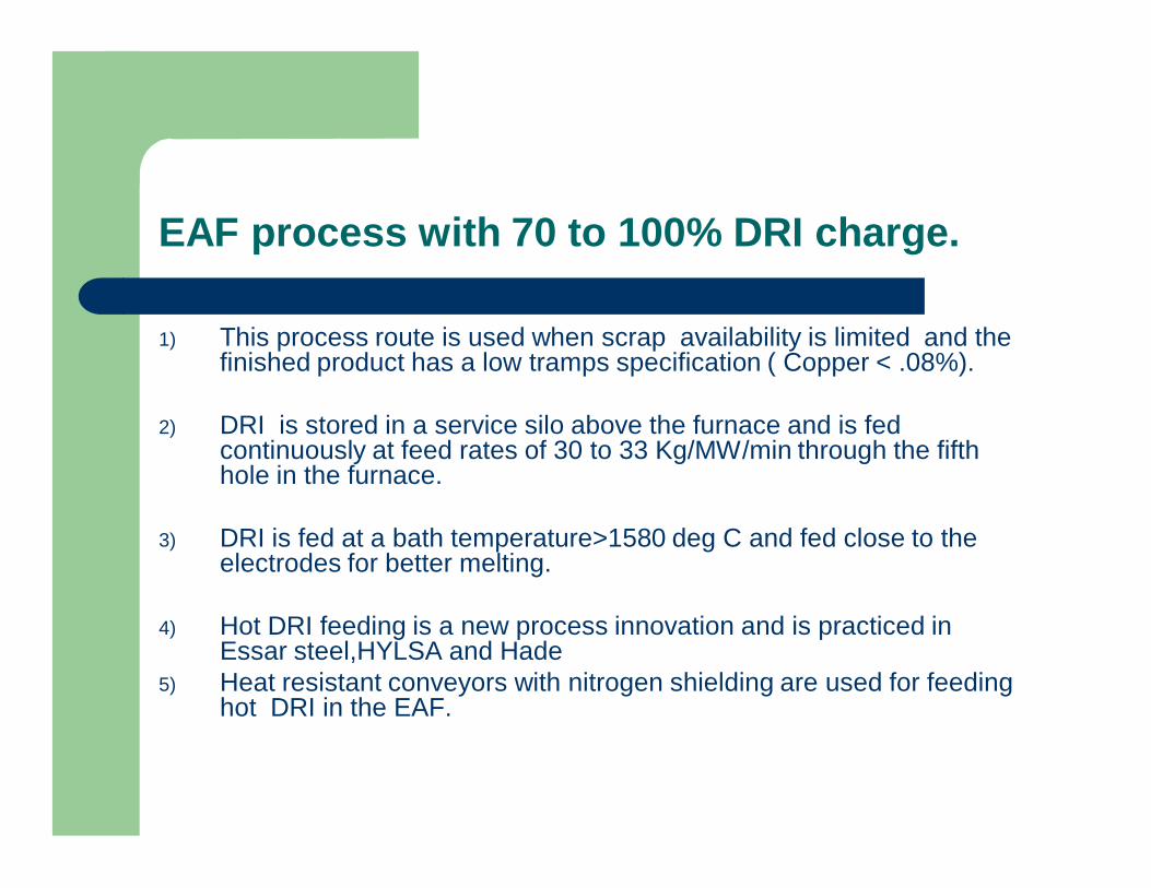
1) This process route is used when scrap availability is limited and the finished product has a low tramps specification ( Copper < .08%).
2) DRI is stored in a service silo above the furnace and is fed continuously at feed rates of 30 to 33 Kg/MW/min through the fifth hole in the furnace.
3) DRI is fed at a bath temperature>1580 deg C and fed close to the electrodes for better melting.
4) Hot DRI feeding is a new process innovation and is practiced in Essar steel,HYLSA and Hade
5) Heat resistant conveyors with nitrogen shielding are used for feeding hot DRI in the EAF.
Foamy slag practice for EAF process
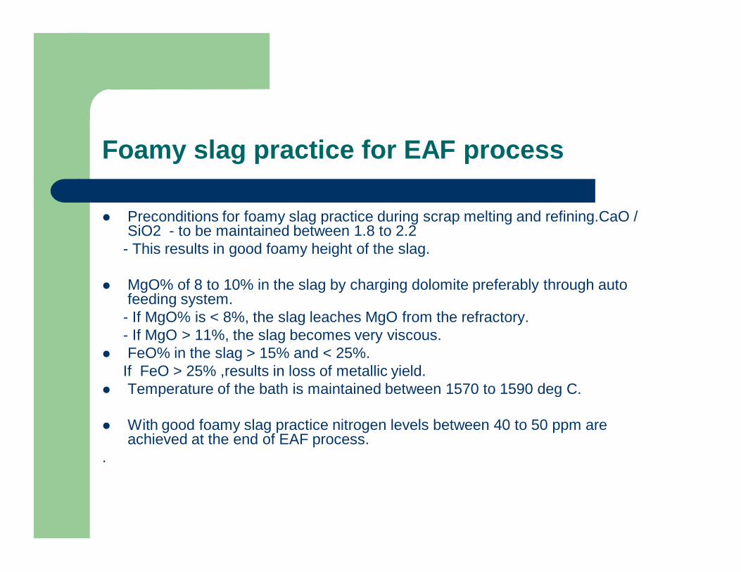
Preconditions for foamy slag practice during scrap melting and refining.CaO / SiO2 - to be maintained between 1.8 to 2.2
- This results in good foamy height of the slag.
MgO% of 8 to 10% in the slag by charging dolomite preferably through auto feeding system.
- If MgO% is < 8%, the slag leaches MgO from the refractory.- If MgO > 11%, the slag becomes very viscous.
FeO% in the slag > 15% and < 25%.If FeO > 25% ,results in loss of metallic yield.
Temperature of the bath is maintained between 1570 to 1590 deg C.
With good foamy slag practice nitrogen levels between 40 to 50 ppm are achieved at the end of EAF process.
.

Foamy slag practice
Foamy slag practice is essential to use long arc practice and higher input into the EAF
Coke breeze is injected at the slag/metal interface along with oxygen.
Iron oxide of slag reacts with carbon, generates CO, causes foaming.
An arc length of 500 mm can be shielded with good foamy slag practice.
Foamy slag is good for ‘P’ removal

Wall mounted oxygen injectors
In modern furnaces, injection of oxygen and carbon is done through wall mounted injecting devices. These function both as a burner and oxygen injectors.
The oxygen jets do not lose coherency till a depth of 2.2 m. Oxygen jet is shielded by LPG which is used as shroud gas.
ADVANTAGES.- Due to the usage of side wall injectors the slag door can be kept closed during
furnace operation preventing ingress of external
- The life of the refractory at slag door is increased as oxygen is distributed homogenously from the side panels of the EAF.
- Usage of Higher % of hot metal and higher productivity. Violent carbon oxygen reactions are eliminated.
New technological developments
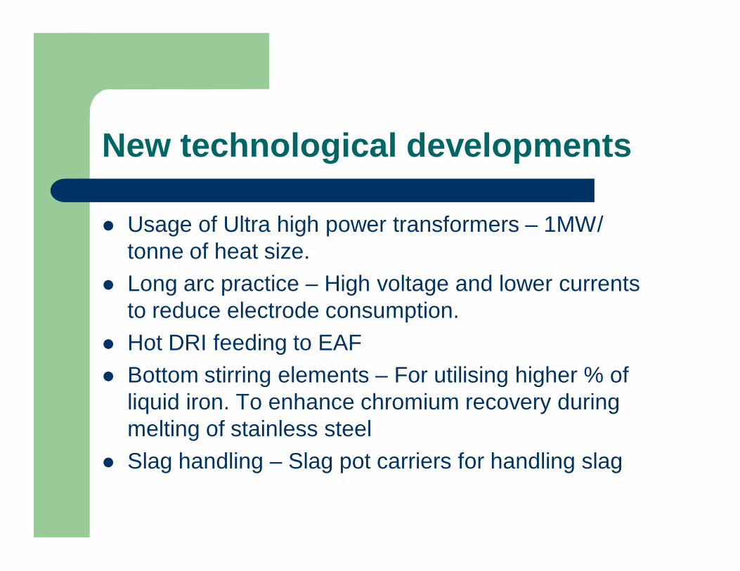
Usage of Ultra high power transformers – 1MW/ tonne of heat size.
Long arc practice – High voltage and lower currents to reduce electrode consumption.
Hot DRI feeding to EAF Bottom stirring elements – For utilising higher % of
liquid iron. To enhance chromium recovery during melting of stainless steel
Slag handling – Slag pot carriers for handling slag

New technological developments
Feeding of Hot DRI at 700 deg C from custom built metallic conveyors with inert atmosphere.
Carbon and injection from the side walls for injecting higher quantities of oxygen and improve foamy slag practice.
Split shell design for quick change of lower shell which improves the availability of EAF for production to as high as 95%.
Continuous feeding of scrap.

New technological developments
Danieli has commissioned a technology for recovering the heat from fume gases of EAF at ABS Italy.The technology is based on Organic rankine cycle and a energy recovery of 5760MW is expected /year.
This technology will result in significant energy savings.

Continuous charging of scrap
Scrap is charged continuously at a feedrate matching the electrical power to reduce electrical disturbances and flicker.
The EAF at Weirton Pittsburg has implemented this technology and is feeding scrap continuously with rest of charge being Hot metal.
In a variant of this technology scrap is preheated to 350 to 400 deg C while being transported on the conveyor using the hot exhaust gas.
Shougang, China has implemented a similar technology for melting scrap and hot metal.
Conarc furnace
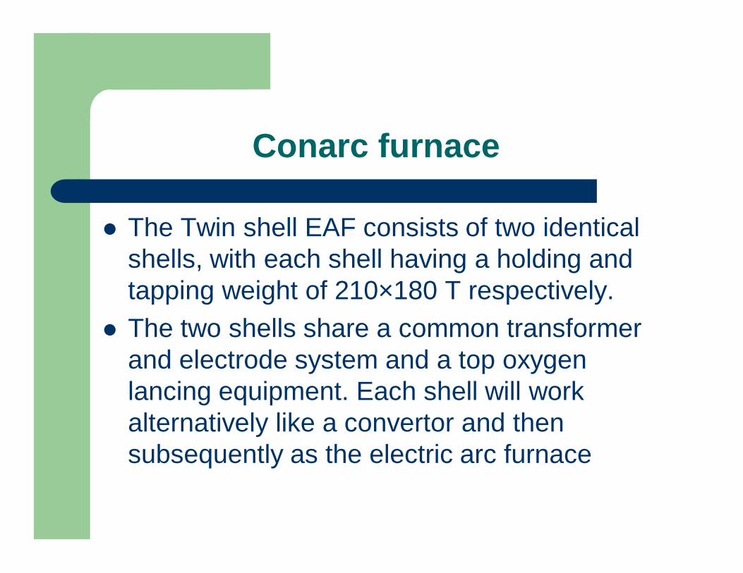
The Twin shell EAF consists of two identical shells, with each shell having a holding and tapping weight of 210×180 T respectively.
The two shells share a common transformer and electrode system and a top oxygen lancing equipment. Each shell will work alternatively like a convertor and then subsequently as the electric arc furnace

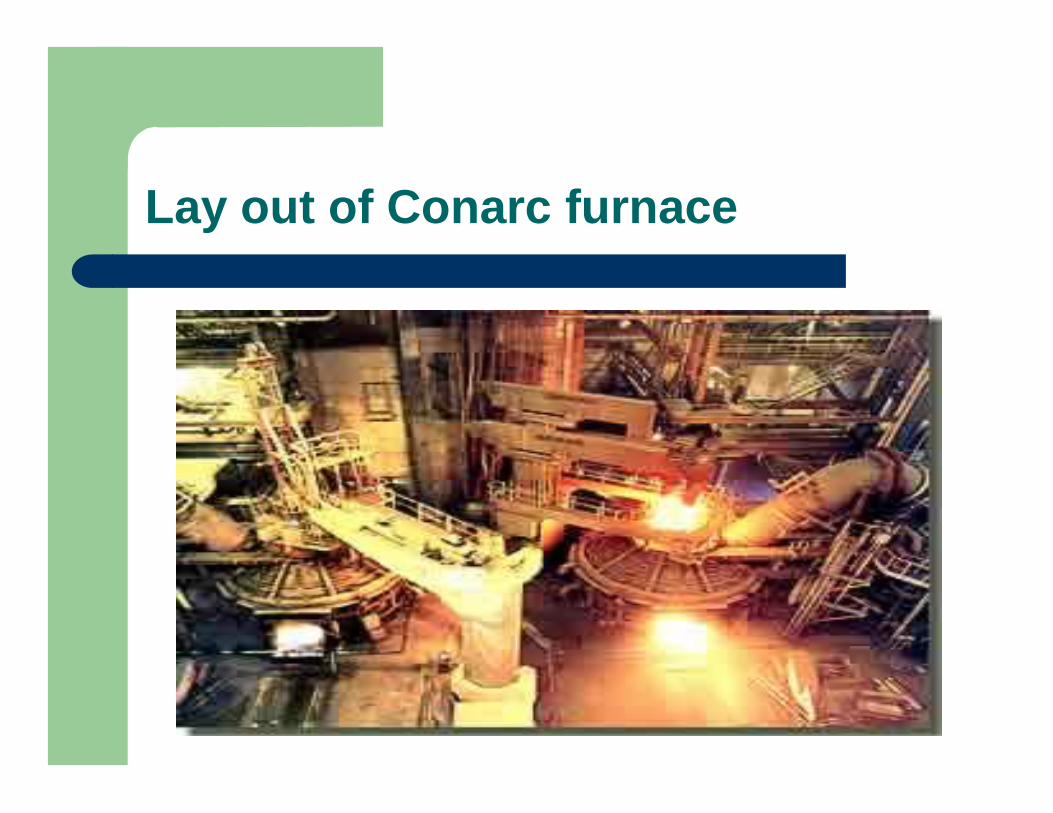
Lay out of Conarc furnace
Conarc furnace
Liquid Pig Iron (50 to 60% of charge weight) is charged in the shell of EAF and oxygen is blown from the top to oxidize the impurities, C, Mn, Si, P. oxygen is blown at a rate of 150-225 m3/min and the convertor part of operation varies from 28-37 minutes. After the oxygen blow is complete, the top lance is slewed to next shell and Electrode arcing system is slewed on the shell.
The rest of the charge i.e. DRI is melted using electrical energy.
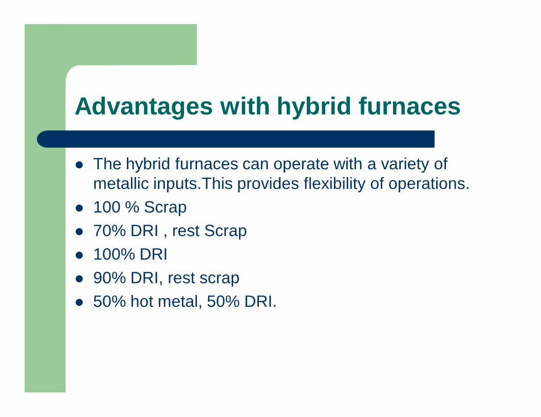
Advantages with hybrid furnaces
The hybrid furnaces can operate with a variety of metallic inputs.This provides flexibility of operations.
100 % Scrap 70% DRI , rest Scrap 100% DRI 90% DRI, rest scrap 50% hot metal, 50% DRI.
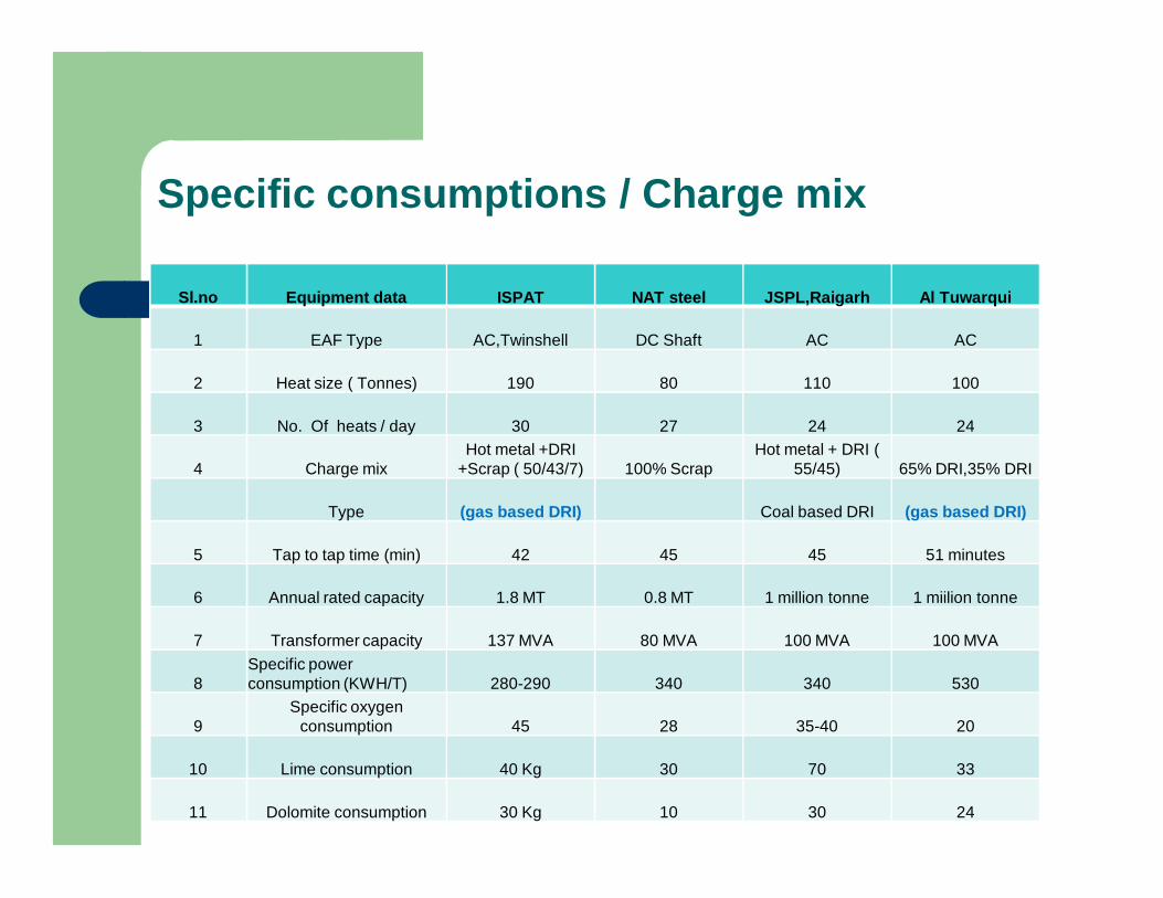
Specific consumptions / Charge mix
Sl.no Equipment data ISPAT NAT steel JSPL,Raigarh Al Tuwarqui
1 EAF Type AC,Twinshell DC Shaft AC AC
2 Heat size ( Tonnes) 190 80 110 100
3 No. Of heats / day 30 27 24 24
4 Charge mixHot metal +DRI
+Scrap ( 50/43/7) 100% ScrapHot metal + DRI (
55/45) 65% DRI,35% DRI
Type (gas based DRI) Coal based DRI (gas based DRI)
5 Tap to tap time (min) 42 45 45 51 minutes
6 Annual rated capacity 1.8 MT 0.8 MT 1 million tonne 1 miilion tonne
7 Transformer capacity 137 MVA 80 MVA 100 MVA 100 MVA
8Specific power consumption (KWH/T) 280-290 340 340 530
9Specific oxygen
consumption 45 28 35-40 20
10 Lime consumption 40 Kg 30 70 33
11 Dolomite consumption 30 Kg 10 30 24

Specific consumptions / Charge mix
Sl.no Equipment data ISPAT NAT steel JSPL,Raigarh Al Tuwarqui
13 EAF refractory lifeSidewall -800 with 1
repair1400 heats with 2 times side repair 600 heats 1000 heats
Bott0m -3000 heats
14 Electrode consumption 1.5 0.9 1.7 2
15 Provision for shell change Yes No Yes Yes
16Metallic yield ( liq steel to charge) 88% 91% 83% 90%
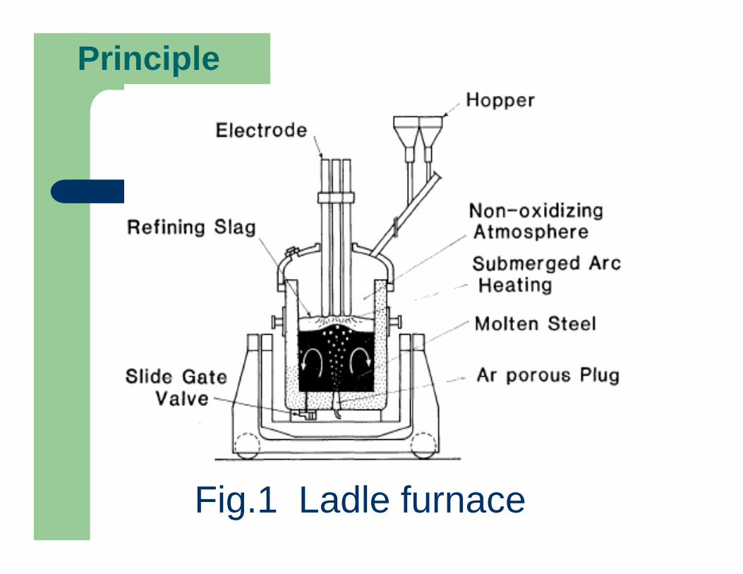
Principle
Fig.1 Ladle furnace
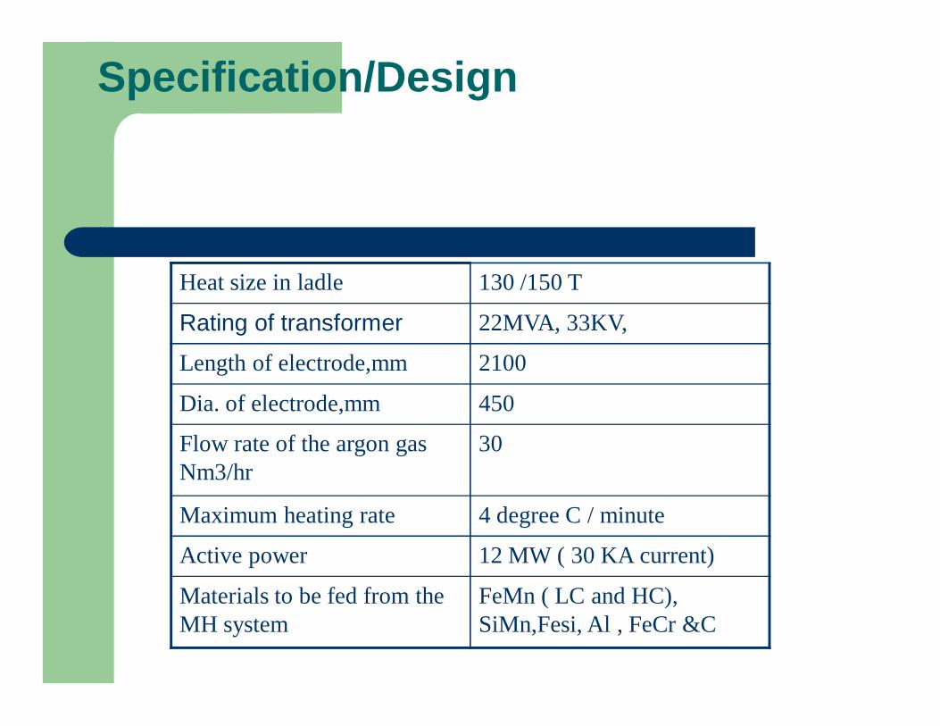
Specification/Design
Heat size in ladle 130 /150 T
Rating of transformer 22MVA, 33KV,
Length of electrode,mm 2100
Dia. of electrode,mm 450
Flow rate of the argon gas Nm3/hr
30
Maximum heating rate 4 degree C / minute
Active power 12 MW ( 30 KA current)
Materials to be fed from the MH system
FeMn ( LC and HC), SiMn,Fesi, Al , FeCr &C
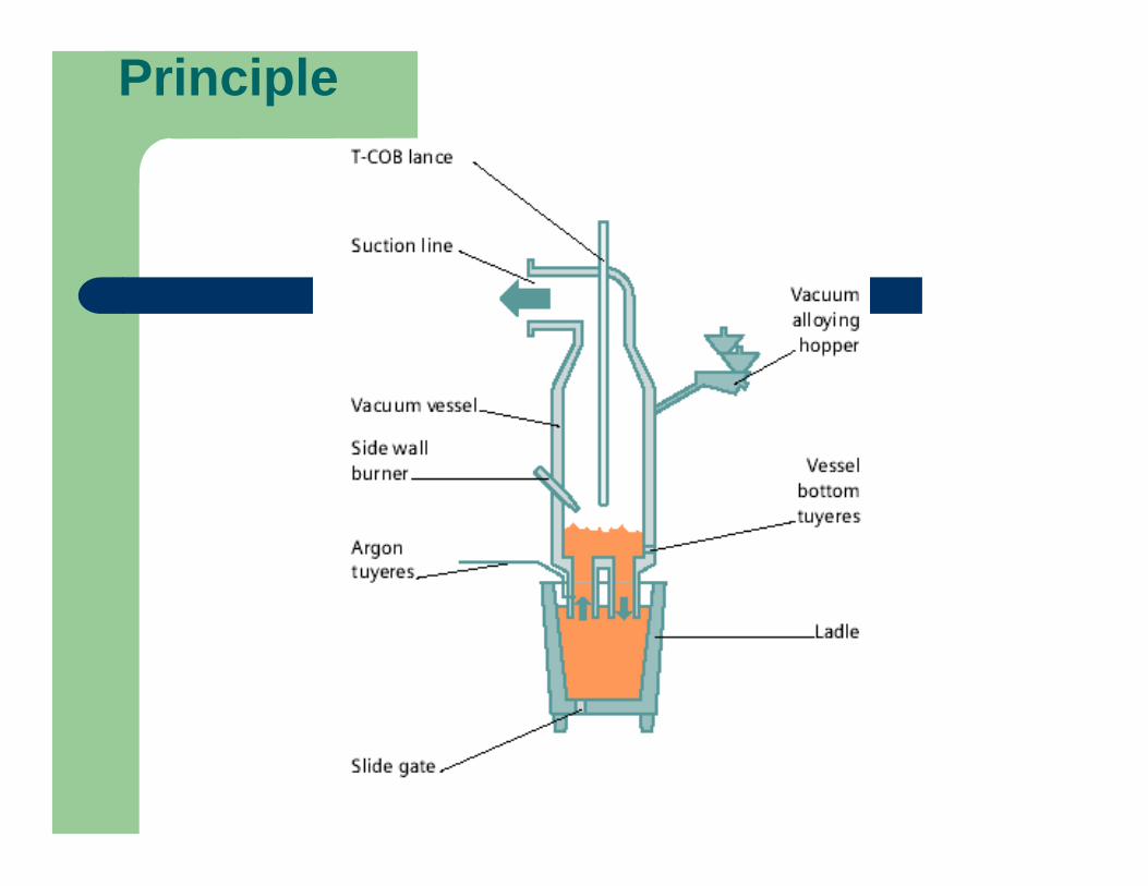
Principle

Challenges for EAF steel making
Enhancing energy recovery from the waste gases.
Limited availability of scrap. As a result power consumption increases with higher % of DRI as charge mix.
High conversion cost due to usage of graphite electrodes and expensive/ limited availability of electrical power.
Thank You