e-z build shed guide - midwest manufacturing...e-z build shed guide 10' × 10' •...
TRANSCRIPT

Shown with rollup door.
Shown with double door.
You can construct your own E-Z frame shed with the help of this step by step guide.
North American softwood
dimensional lumber sizes:
Nominal Actualin × in
1 × 4 ¾ × 3½ 1 × 6 ¾ × 5½ 2 × 4 1½ × 3½ 2 × 6 1½ × 5½
GENERAL
INVENTORY
FRAME PREPARATION
E-Z BUILD SHED GUIDE10' × 10' • 10' × 12' • 10' × 14' • 10' × 16'
Prior to beginning construction, the area selected for the shed location must be level and cleared of obstructions.
PRO-RIB® STEEL SIDING
PLEASE NOTE: This shed construction aid is intended solely to provide general knowledge as to one of the ways a shed may be constructed. We suggest you check with your local building officials regarding site location, permit procedures, safety regulations and specifications of materials used to construct your new storage shed. Builders who utilize this aid must proceed at their own risk and are solely responsible for complying with all building codes which pertain in their community. Midwest Manufacturing hereby disclaims all liability for any damages whether consequential, incidental, special or otherwise, which may result from following this do-it yourself aid.
COPYRIGHT BY Midwest Manufacturing 2016 www.midwestmanufacturing.com Sku# 101-
Separate all lumber, hardware, etc. into individual stacks of like items.
Unfold each frame, setting aside two framesto be used as end walls. From 1×4 pine boards, cut gusset plates 6" long:• 20 for an 10' building • 24 for a 12' building• 28 for a 14' building • 32 for a 16' building Apply gusset plates on each side of the top and bottom fold locations. Use four 8d nails on each gusset plate. Frames used as end walls require only one gusset plate at the top and bottom on the side opposite the metal plates.
BUILD
104
9 ⁄ 16"
131
3 ⁄ 16"
96"
79"
69 ¼"
73 13 ⁄16"
10'
Frames available in 79" or 96" heights
1×4 6" gusset plate
Treated 2×4 bottom frame member
1×4 6" gusset plate
1×4 6" gusset plate
6"
10'8' walls
10'
1 1⁄2" 1 1⁄2"
Figure 1
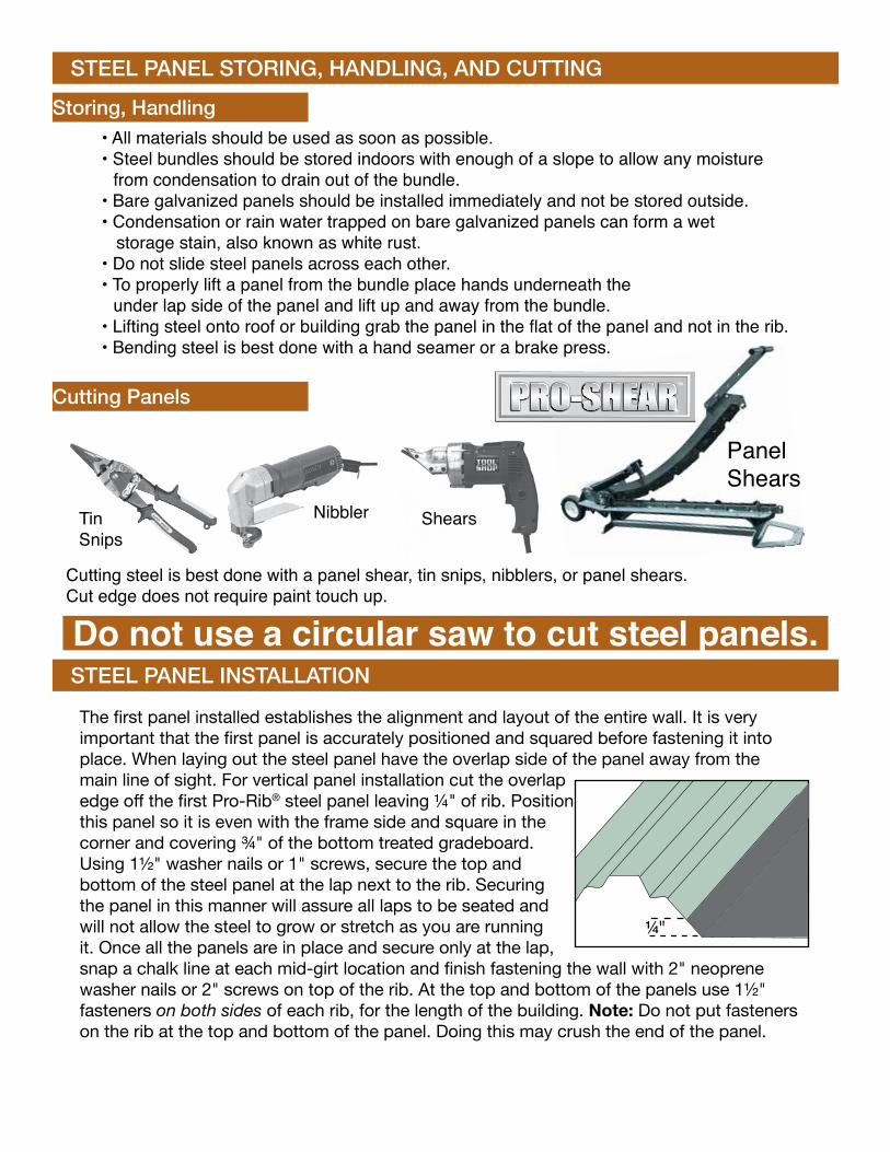
STEEL PANEL STORING, HANDLING, AND CUTTING
Do not use a circular saw to cut steel panels.
Storing, Handling
Cutting Panels
• All materials should be used as soon as possible.• Steel bundles should be stored indoors with enough of a slope to allow any moisture from condensation to drain out of the bundle.• Bare galvanized panels should be installed immediately and not be stored outside.• Condensation or rain water trapped on bare galvanized panels can form a wet storage stain, also known as white rust.• Do not slide steel panels across each other.• To properly lift a panel from the bundle place hands underneath the under lap side of the panel and lift up and away from the bundle.• Lifting steel onto roof or building grab the panel in the flat of the panel and not in the rib.• Bending steel is best done with a hand seamer or a brake press.
Nibbler TinSnips
Shears
Panel Shears
Cutting steel is best done with a panel shear, tin snips, nibblers, or panel shears.Cut edge does not require paint touch up.
STEEL PANEL INSTALLATION
The first panel installed establishes the alignment and layout of the entire wall. It is very important that the first panel is accurately positioned and squared before fastening it into place. When laying out the steel panel have the overlap side of the panel away from the main line of sight. For vertical panel installation cut the overlap edge off the first Pro-Rib® steel panel leaving ¼" of rib. Position this panel so it is even with the frame side and square in the corner and covering ¾" of the bottom treated gradeboard. Using 1½" washer nails or 1" screws, secure the top and bottom of the steel panel at the lap next to the rib. Securing the panel in this manner will assure all laps to be seated and will not allow the steel to grow or stretch as you are running it. Once all the panels are in place and secure only at the lap, snap a chalk line at each mid-girt location and finish fastening the wall with 2" neoprene washer nails or 2" screws on top of the rib. At the top and bottom of the panels use 1½" fasteners on both sides of each rib, for the length of the building. Note: Do not put fasteners on the rib at the top and bottom of the panel. Doing this may crush the end of the panel.
¼"

SQUARE THE BUILDINGAt base of building, measure diagonally. Adjust building until AD=CB. Building is then square.
Cut treated 2×4 rim joists: 120" for a 10' building; 144" for a 12' building; 168" for a 14' building; and 192" for a 16' building. Place the rim joists 10' apart in the area where the shed is to be set. Plumb and temporarily brace both the front and back walls at the proper ends of the rim joists. Nail rim joists to the end walls using 10d nails. Place a temporary brace across the roof frame members. Stand up the remaining frame and nail rim joists to the base. Measure and cut outside girts the same lengths as the rim joists. Square the building and keep frames plumb. Position top girt according to your soffit plans (page 5). Nail outside girts to the sidewalls evenly spaced between the top girt and the bottom girt, that is: another treated gradeboard over the rim joists; a 2×4 girt @ 30" up the frame; and then another. See illustration.
A
C
B
D
ERECTING THE BUILDING
BACK AND FRONT WALL FRAMINGToenail a 2×4 girt 30" up from the bottom of the treated gradeboard; and another 30" more up from that. Toenail another 2×4 girt up 20" from that to frame in your optional window. Cut 2×4's to fit and fasten with 8d nails. Using another frame for the front wall as shown.
NOTE: Frames with 8' high sides are used in these instructions to accommodate a 7' high Rollup door. Plan and adjust your own building to accommodate your particular needs.
Back Wall Front Wall
2×4 Girts toe-nailed into frame
Optional frame out for 60×20 window
2×4 Girts and nailers nailed flush with frame
2×4 girt rollup door support
Gusset plates to inside of building
Rough Opening for Roll up door 6' W × 7' H
Vertical nailers, nailed onto back of frame
24"
20"
30"
30" 26"
26"
25"
72"
84"

STEEL PANEL FASTENINGProper Lapping of Steel
Proper Fastener Tightness
Screwing of Steel Panels Roof Sheets -Use 2" Woodgrip screws on rib top or 1" screws in the flat. Peak & Eaves of roof sheets -Use 1" Woodgrip screws installed in the flat surface Wall sheets -Use 1" Woodgrip screws installed in the flat surface
Note: Screw lengths may need to be adjusted.
Proper lapping of steel panel is very important in the panel’s ability to prevent leaking.
The anti-syphon drain channel must be clear of debris and obstructions for the panel’s ability to minimize the potential of capillary action of water from getting under the steel panel.
Fastener tightness is critical in the longevity of the fastener’s ability to help prevent leaks and structural load carrying capacity. Over-torquing of screws will reduce the screw’s withdrawal capacity, regardless of the construction materials involved. Under-torquing of screws will increase the potential of roof leaks.
Fastener location is critical for installers to minimize the potential of oil canning, dimples, and other appearance related issues.
Note: Both professional and first time installers have fewer problems with oil canning, dimples, and other appearance related fastener seating problems if they install them on top of the rib.
Fastener Specifications: Roof: Nails must be installed on top of the rib. Screws can be installed on top of the rib or in the flat surface of the panel between the ribs. Wall: Nails or screws can be installed on top of the rib or in the flat surface between ribs.
Nailing of Steel Panels Roof Sheets -Use 2½" E-Z Seal nails installed on top of the rib. Top & Bottom of wall sheets -Use 1½" Neoprene nails installed in the flat surface Wall sheets -Use 2½" E-Z Seal nails installed on top of the rib
Undertight OvertightProper
Underseat OverseatProper
Overlap

FLOOR SUPPORTS/SHEATHING
END WALL, SIDE WALL, AND ROOF STEEL
From treated 2×4’s cut and fasten floor supports and ¾" sheathing. See illustrations.
Toe nail in place 2×4 treated floor supports. (typical)
1×4×6" gusset plates at top and bottom fold locations (typical)
23¼"
21¾"
10'0"
12'0"
10' × 12' Floor plan shown
22"
22"
22"22½"45¾" 45¾"
1½"
1½"
22½"
Notch for Uprights
Seams10'×12'FloorShown
10'3"
27"
48" 48"
96"
48"
Fascia Board
L-6 Fascia trim
Soffit panel
Small J-trim with frieze
You may use a 1×6 soffit board.Position top girt accord-ingly.
Roof Steel
Wall SteelTreated Floorboard
Floor Supports
Wall Girts
Universal RidgecapFlat Roof Purlins
Measure, cut and fasten roof purlins and 1×6 fascia board. The bottom edge of the peak purlin should be 6" from the peak. Measure, cut and fasten roof steel and universal ridgecap.
Apply small J-trim with frieze, soffit panels and L-6 fascia trim. Measure, cut and fasten wall steel panels.
Roof Steel
Side Wall Steel
Finish the building with Corner and Gable trim.
Top girt
1×6 Fascia Board
1×6 Soffit BoardL-6 trim

ROLLUP DOOR
TRIMS
Cut top doorway cap 2" longer than door opening. Notch doorway cap 1" in on both ends. Bend middle piece down at 90º angle. Apply top doorway cap into opening. Cut side doorway cap the height of door opening. Fasten caps with 1" screws.
J-TRIM
Cut a piece of J-trim 2" wider than door opening. Notch both ends 1" in and bend middle tabs down. Slide wide side of J-Trim under Steel Siding at top outside face of opening. Cut 2 pieces of J-trim the height of the door opening. Slide wide side of J-Trim under Steel Siding on outside face of the opening. Fasten wall steel and J-Trim. It may be possible to use hem trim on steel without rib if you desire.
DOOR OPENING TRIM Doorway Cap
J-Trim, Hem Trim
Steel Siding
J-Trim
Door Trim
2×4Headers
Extra 2×12Header
2×4 End Frame
Rollup Door
HEM TRIMJamb Pole
1"1/2"
2-1/2"
SidewallSteel
SoffitPanel
Top Girt
SidewallSteel
SoffitPanel
Top Girt
Follow manufacturer's installation instructions for installing Roll Up door.
Steel Siding
2×4Headers
Extra 2×12Header
Rollup Door
1"
1"7/16"
3/4"2-13/16"
1/4"Soffit
J-Trim with FriezeSmall
PREMIUM GABLE TRIM
Eave Trim
10
4
112
34
34
150°
112
112
Sidewall SteelCornerTrim
Roof Steel
PremiumGable Trim
CornerTrim
GableTrim
Eave Trim
Roof Steel
Sidewall Steel
CORNER & GABLE
TRIM
SOFFITL-6 FASCIA
5-1/8"
5-1/8"
6-1/4"
1-1/2"
1/4"

OPTIONAL SERVICE DOOR FRAMING
Door units should be installed before the steel is applied. For best results, the side of the door should be located between the ribs of the steel.
1. Nail (2) 2×4 vertical nailer onto the inside of the girts (R.O. width +3").
2. Nail a 2×4 horizontal nailer onto the outside of the vertical nailer (R.O. height+1½").3. Cut out girts between vertical nailer.4. Nail a 2×4 horizontal jamb to the bottom of the horizontal nailer.
5. Nail 2×4 vertical jambs to insides of the vertical nailer.6. Add 2×4 spacer blocks, cut to fit, between girts.
Insert the door into the frame-out and fasten it in place from the outside.
2×4 Spacer Blocks
Vertical Nailer
Vertical Nailer
Horizontal Nailer
Rough OpeningRough
Opening
Girt
Girt
GirtGirt
EZ Frame Upright
2×4 Vertical Jamb
TOP VIEW FRONT VIEW
* Notch as necessary
Service Door Framing
36"×80" RO 381⁄16"×8015⁄16"Shed Service Door
White or brown with 22"×36" lite
White or brown blank

OPTIONAL WINDOW FRAMINGInstall window unit before steel is applied. For best results, the side of the window should be located between the ribs of the steel. Frame out openings as shown. For traditional window framing, cut out girts between vertical 2×4’s last. Insert the window into the frame-out and fasten it in place from the outside.
2×4 Spacer Blocks
Vertical Nailer
Vertical Nailer
Horizontal Nailers
Rough Opening
RoughOpeningGirt
Girt
Girt
Bottom Treated Gradeboard
TOP VIEW FRONT VIEW
Window Unit Window Unit
DOUBLE ANGLE TRIM
DRIP CAP
1-1/2"
2"
1/2"
2-1/2"
1-1/4"
1/4"
• Built in “J” Channel on screen units.• Frame and Sash are completely weather stripped with woven pile.• A durable baked enamel finish is standard, and is available in white or brown.• Shipped ready to install.• Center mullion for a sturdier window.• Nylon track for an easy sliding sash.48" W×36" H; RO Storm unit White only60" W×20" H; RO w Screen White or Brown
NOTE: Screen units are to be installed on the exterior of the bldg. Storm units are installed on the inside of the building. Therefore when ordering windows you generally just order a screen unit. Sometimes you may order a screen and a storm, but it is highly doubtful that you would be using a storm unit alone.
wwww.midwestmanufacturing.com Available at:
NOTE: Windows with built in J Channel are flashed in white or brown. Windows with no J flashing allow you to order color matched J-Trim to flash around window.
Built in “J” channel

FLOOR DETAIL
SIDE VIEW
GABLE SHED WINDOW & DOOR OPTIONS
21¾"
10'0"
Treated Rim Joist
Treated Bottom of Prebuilt EZ Frame
Treated Floor Joist Supports
¾" Plywood Floor
36"
3'0" 3'0" 6'0"
WALL DETAIL
2×4 Cripples
6'7"6'7"
6'4"
10'0" 10'0"
¼" Waferboardsub-sheathing
2×4 Supports
1×6 Fascia 1×6 Fascia
20×16 DH
Window20×16 DH Sliding GlassWindow
3'0"
DOOR DETAIL
6'4"
Door Front Door Back
1×4 nailer for lap siding
1×4 outside door frame
Primed hardboard lap siding
Note: Cut ¼" waferboard to door size, trim inside and outside of door as shown, then apply primed hardboard siding.
1×4 Trim
1×6 back of door frame
Waferboard
ROOF FRAME DETAIL - TOP VIEW
21¼"22½"22½"9¾"
10'0"
Treated Offset Back to 1" with spacers in between to allow for door opening.
2×4 BlockingEZ Frame2' O.C.
Prebuilt EZ Frame
Roof Center Line
36"
1×4 Corner Trim
Hardboard lap siding
1½"

FLOOR DETAIL
END VIEW WITH WINDOW
GABLE SHED WINDOW & DOOR OPTIONS
10'0"
36"59¼" 72¾"
36"
36"
36"
59¼"
59¼"
72¾"
72¾"
3'3"3'3"3'3"
WALL DETAIL
6'10"
6'10"
6'4"
101"
14'0"
14'0"
10'0"
1×6 Fascia
Double 2×4 Door Header 2×4 Support
1×6 Fascia
EZ Frames
1×4 Corner Trim
T1-11Siding
Side View with Single Door
Note: Gusset Plate and Brace Roof Area the Same as the Floor Detail
Note: Cut T1-11 to door size and trim front and back before door is installed.
DOOR DETAIL
14'0"
1×4×6GussetPlates
Treated Floor Joist Spacers
2×4 Cripples
24×16RanchWindow
51½"
2×4 Frame Back of Door
79"