dynamic response of single-ply membrane roofing systems
TRANSCRIPT

Journal of Wind Engineering and Industrial Aerodynamics, 41- 44 (1992) 1525-1536 Elsevier
1525
Dynamic response of single.ply membrane roofing systems
N.J.Cook
Director, Geotechnics and Structures, Building Research Establishment, Garston, Watford WD2 7JR, UI~.
© UK Crown copyright - Building Research Establishment, 1991
Abstract The use of a servo system, able to reproduce measured time-varying wind pressures on areas of cladding at full scale, has shown the dynAmlc response of some porous and flexible claddings systems to be non-linear and frequency- dependent, indicating that static proof testing methods may be inappropriate.
1. INTRODUCTION
As long as a multi-layer cladding system acts structurally as a single unit, the way that wind loads are distributed through the layers is usually assumed to be irrelevant. Nevertheless, there are a number of formA of construction where the way that the wind loads are distributed through the multiple layers is important. This is especially true with cladding system~ which are assembled on site from different components made by different manufacturers. Each of the components can be tested for strength and durability, but the share of the wind load that each layer takes depends on the way that they act together as a system. Until recently, system performance could only be assessed by methods that exposed the cladding to static or simple cyclic loads. The development of the BRERWULF system (Cook, Keevil & Stobart 1988), which is able to reproduce measured time-varying pressures on areas of cladding at full scale, now enables the performance of these systems to be analysed in some detail. So far only a few system~ have been tested using BRERWULF, but studies have included two characteristic types:
Rain~¢reen 0ver¢laddin~ - a stiff air-permeable skin added to existing buildings to prevent rain penetration or improve insulation, which is separated from the original external walls by a significant air gap; and
Elsevier Science Publishers B.V.

1526
Mecb~nicallv-fixed single-ply membranes, flexible impermeable membranes used to weather-proof fiat roofs, which are fixed at intervals and which lift between fixings under the suction action of wind.
The latter have been extensively studied and are the principal subject of this paper.
2. THEORETICAL BACKGROUND
A prominant feature of multi-layer cladding systems where the outer skin is porous or flexible is that the wind loads have two alternative load paths from the outside skin through to the structural members:
pneumatic load vaths - where the load is shared through the layers by differences in pressure across them; and
structural load path~ - where the loads pass through the fixings.
In both the cases considered here there is a void, a trapped volume of air, vented by openings through one layer. In the case of rainscreen overcladding, the venting is through the permeable outer skin to the fluctuating wind pressures. In the case of the single-ply membrane roofs, the venting is through the roof deck to the internal pressure of the building. In both cases the dynamics of the pressure characteristics are described by the well-known Helmholtz equation (Strutt 1896):
d2cpi/dt2 (Pa L O)/(y, PsbB) ÷ dcpi/dt I dcpi/dt I (p, 02 q)/(2CD 2 ya 2 A p,~2) + A Cpi -~ A Cpe ...(1)
where: %0 and Cpt are the external and void pressure coefficients, O is the void volume, A, L and CD are the area, depth and discharge coefficient of the vent, p, and Ta are the density and ratio of specific heats for air, P,b~ is the absolute pressure, and q is the dynamic pressure. There are two forms of solution to Equation(I): an oscillatory solution representing Helmholtz resonance when the damping is small and a gradual decay when the damping is large. The expectation for small vents and low overall porosity is for the damped decay, which Holmes (1980) shows has the solution for the decay time constant, t:
t ---- (Cpe - Cpi)~(pa 0 2 V) / (C D ~a A Pab6) ...(2)
where V is the wind speed. Recently, Harris (1990) has extended the
through both layers, with the solution: theory to account for openings

1527
t = (Cpw - cpl)½[(pa 0 z V)/(C D Ta Patw)] [Aw A~(Aw2+AI2) a~] •.(3)
where the subscripts w and I denote the windward and leeward layers. This was developed for assessing the fluctuations of internal pressure in room~ having openings to the windward and leeward faces. It is valid where neither the windward or leeward openings dominate, that is in the range 0.5 < A~/A l < 2. Thus Equation(2) is sufficient in this context because the permeability of one layer dominates in both the cases considered.
The Helmoltz equation (1) represents a process where air entering or leaving the void adiabatically compresses or expands the air trapped in the void, assuming the volume of the void to be constant. However, i f either of the layers is flexible, the volume will expand and contract in response to the changes in pressure and the air displaced by this movement must also pass through the openings, slowing the response time. Vickery (1986) approached this problem in termg of the bulk modulus of the air, k,, and of the building, kb, and showed that the result was the same as for the rigid case except that the effective volume, Oe~ , increases to:
Oeff ffi 0 (I + ka/k b) ,..(4)
replacing the actual volume, O, in the previous equations. He demonstrated that the time constant for the internal pressure of large-span arenas could be increased by a factor of five. Clearly, for very flexible layers, the response time will be dominated by the volumetric change.
A fuller description of the theoretical background may be found in Cook (1990).
3. RAINSCREEN OVERCLADDING
A typical rainscreen cladding system used in the UK to renovate large-panel system buildings built in the 1960s is shown in Figure l(a). In this system studied at BRE, structural T rails are fixed at intervals to the external walls, insulation boards are likewise fixed between the railsr, then the panels of the external skin are screwed or riveted to the T rail. Equation(2) predicts that the decay time constant is very fast, less than 0.1s, and this was confirmed by BRERWULF tests on a 3m by 5m area of clad3ing. This implies that practically all the fluctuations of wind pressure acting on the outer skin are transmitted through to the void to act directly on the original building wall, resulting in minimal loads on the outer skin and its fixings. In practice, however, the distribution of pressure varies over the outer surface, resulting in net flows into the void where the pressure is high and out of the void where the pressure is low. The T rails tend to divide the void into separate nodal volumes, each connected to

1528
its immediate neighbours as shown in Figure l(b). If the flow through these connections and the outer skin is modelled by the orifice-plate meter equation:
Qf f iCDA(2 I A p l / p , ) ~ ...(5)
where Q is the volumetric flow rate, I Apl is the modulus of the pressure difference across the orifice and the other symbols are as before, continuity of mass requires that the net flow into each void node is zero, hence:
(An I Ap. [ ~ ) = 0 ...(6)
for all n connections into the node. Equation(6) is conventionally used to calculate the internal pressures of rooms ~n multi-room buildings and ~ .F , RWULF tests confirm its applicability in this case also.
The principal loads on the outer skin and its fixings comes from the variation in pressure distribution over the skin. The measured response to realistic fluctuations of pressure confirn~ that good estimates of these loads can be made using Equation(6) on a quasi-static basis.
• . . . . . . . . . 1 . . . . . . . . . . . . . , , . : , I . . . . . . . . . . . . . . . . , . . . . '.,.,..:...,,..,..,..,,.,.,...~:,.,t: ,:t.,,.,,:t:i~:l:l.,,:t:. t,t:l:,t.d,,=d~.:i~,L,l,I, .~.~.,'.=:.=..~.=,;'.t.=.~.=,~.l~.=':";.: P ~ r ~ * ¢ = n ~ * = t ~ n t:'.':';.='t:'~ i [ : : K t : ' ~ ' ; ' ; : ' ; ' = ' f = ' K ; ~ ' f . " ( : ' ) ' _ = ' .t;~ };= .~;: .~[~ t;:1;=}[; } '[=';'[:;;;'~" ;H.:~ ;~.=r ~.=~ ::.=~'z.:~,=~:~; ~;~ ='t~='~';:~.y)';'i';"lt:~.';';")';'i';i'=T;"; "' " ) ' ; ' . . . . . . . . . . . . . . . ~ . , ....... ,.. ,,...,,..,.,,........,,.,. ,...,, ..,..;, ,:,, .,,., .,.;, ,:~; ,'~,,;, ,-...;,,..,
Air space Leakage~"b:i- [ ~:~''; paros . . . . . . J L . . . . .
Outer sheeting [
(a) Typical form of overcladding with insulation
Building internal pressure }
External pressures
(b) R~gresenlation of flow paths
Internode connections
F i g u r e 1 Rainscreen cladding system

1529
4. MECHANICALLY-FIXED SINGLE-PLY MEMBRANES
If the balance of the porosity of the rainscreen cladding in Figure l(a) were reversed so that the outer skin was impermeable and the dominant venting of the void was to the internal pressure of the building, then the pressure in the void would equalise to the relatively steady internal pressure and the fluctuations of external pressure would be taken by the outer skin. However, if the impermeable outer skin was very flexible, it would deflect under this loading and alter the pressure in the void through the volumetric change.
Weather-proof membrane~ ~e Insulation board Pl ~ / Profiled steel deck
_ ,,.~ Purlin ~'~2 ---
Pi
Figure 2 Mechanically-fixed single-ply membrane system
Figure 2 shows a typical mechanically-fixed single-ply membrane system comprising, from bottom to top: purlins or rafters which support the main roof deck and transmit the loads to the main structural members; a profiled-steel sheet deck fixed at intervals to the purlins; a polyethylene or similar membrane laid over the deck as a vapour check (but which may be omitted), insulation boards fixed at intervals through the vapour check to the deck; and finally, a very flexible weather-proof membrane fixed at intervals through the insulation and vapour check to the deck. The fixings are usually self-tapping screws and penetration of the vapour check gives a small porosity which allows air to pass through to the underside of the main membrane. Without the vapour check, the air passes through the larger porosity of the joints in the deck sheets. The main membrane may be fixed in a variety of ways: with washers or long bars fixed with screws which penetrate the membrane, requiring bonded patches to restore the weather-tightness; or with hidden f~dngs that are bonded to, or grip the membrane from the underside.
Initially, the void volume is small, but when the membrane rises it becomes large. As the membrane is very flexible, the ratio of bulk moduli, kdkb, in Equation(4) is initially very large, but reduces with deflection as the membrane stiffens by catenary action. The porosity through the vapour check is very small, but even without it the porosity through the deck is still small. This results in

If
values for the decay time constant, t, from Equations(2) and (4) in the range from several seconds to several minutes, but which varies with time depending on the deflection of the membrane.
Single-Ply Rool comprising reinlorced PVC membrane, insulalion boards, vapour check, profiled steel clack and coM-mled purlins
1530
.s kPa ÷l~ kPl
Pressure difference across vapour check
~ T " ' " l ,n ' l ........... rr', .... ~v, ' n , . . . . . . I , " ' ~
..o l~a ,~6 kPa
Pressure dlfferenee across dOCk
,4 kP,, 0 'rimo (minutes) 30
Figure 8 Response at decking centre during storm with -8kPa peak value
Fluctuations of external wind pressure slower than the response time are resisted directly by the main membrane and the loads transmitted through membrane tension to its fixings. Fluctuations faster than the response time are transmitted pneumatically to the vapour check or the deck surface. However, the variation of time constant with membrane deflection means that this balance is continually changing and the system response is very non-linear. Increasing the applied suction increases both the pressure difference and the volume in Equation(2) implying an increase in the time constant. However, this effect must be more than offset by the decrease in the effective volume given by Equation(4) through the stiffening of the membrane, since measurements using BRERWULF clearly show that the higher the applied suction, the greater the proportion borne directly by the membrane.
Figure 3 shows the results of a BRERWULF test on a system with a reinforced l~VC main membrane, using BRE's standard 7-hour storm trace and measured at

1531
the centre of a deck sheet. The top trace shows the load across the membrane is the mean suction and the low-frequency components. The high-frequency components are taken by the vapour check and the deck with a zero mean value. Here at the centre of the deck sheet, the vapour check shows a single.sided response, resisting suctions by pressing up against the underside of the insulation boards, but falling slack into the deck troughs under pressure. The deck takes the remainder of the loads, since the sum of all three components exactly balances the applied suctions. At the deck edge, the joints provide less resistance than the vapour check and there is little load on the deck. Removing the vapour check reduces the time constant and changes the balance so that the main membrane takes components up to higher frequencies.
Static structures are conventionally designed to withstand the maximum load expected in their lifetime by a suitable safety factor. It would therefore be convenient for the design of the main membrane and its fixings if its loading could be expressed as a proportion of the design applied load. Table 1 gives the peak load applied to the system in successive tests in the first column, with the corresponding proportion of this load taken by high and low elastic modulus membranes in the second and third columns, respectively. The proportion increases with increasing load and is larger for the higher-modulus membrane. The proportion also varies with the porosity of the vapour ch~k and deck. For example, increasing the deck joint overlap from ½ corrugation to 1½ corrugations can reduce the membrane loads by about one third. Removing the vapour check increases the membrane loads by about one third for the high modulus membrane, but nearly doubles the membrane loads for the low modulus membrane. These variations show how important it is to verify system performance rather than relying solely on component performance tests.
Table 1. Proportion of peak load taken by main membrane
Test type: BRERWULF UEATC Membrane modulus: High I Low b High° Low b Peak load (kPa) Proportion taken:
-2 0.71 0.68 0.58 0.38 -3 0.71 0.62 0.40 -4 0.74 0.68 0.62 0.42 -5 0.76 0.74 0.62 0.42 -6 0.82 0.75 0.66 0.73 c -7 0.87 0.78 0.71 0.74 ~ -8 0.87 0.80 0.75 0.93 ~
a Reinforced PVC, b EPDM, c after failure ofvapour check

1532
5. SIMPLE PROOF TEST PROCEDURES
The first proof tests for cladding and roofing were carried out statically using a steady air pressure, and this is still the standard procedure in the USA, as in the Factory Mutual or the Underwriters Laboratories standard tests. In this context, static tests will give no load on the porous rainscreen cladding skin and the full load on the main single-ply membrane, which is clearly unrealistic.
In 1984, BRE devised a cyclic test sequence (Redfearn 1984) which was based on counting the expected load cycles in ranges of 10% amplitude and applying these cyclically to the specimen. Some effort was made to reproduce the random order of the real process by mixing the cycles into five repeating sequences. The intention was to reproduce the fatigue history of the expected lifetime according to Miner's rule. The cycles were applied slowly, so as to give a quasi-static response.
SInole-Ply Roof comprising reinforced PVC membre~e, insulation boards, vapour check, profiled steel de~ and cold-rolled purlins
. . , , . . . , . . . . . . L . . ; . . . - . . . . . . . . 2 2 . . . . . .
.,oo,.I . . . . . I , ,+lOOPa • va our oheok Preauredlflerencmaorou va our oheck
,100Pa +to0pa
• t00 pt
Proueull) difference n(a'ou ~ k at deoklng Joint
Pressure dlfferonoe across deok st dtnklng mntm
0 11me (mlnum)
Figure 4 Response to UEATC 0Pa to -100Pa oscillating pre-test procedure
More recently, the UEATC has adopted as standard for European agrement tests a similar test method devised at WSP Aachen in which the cycles of load a reduced to five levels (40%, 60%, 80%, 90% & 100% of the peak value) and the sequence of application is also simplified. The sequence starts with half the
1533
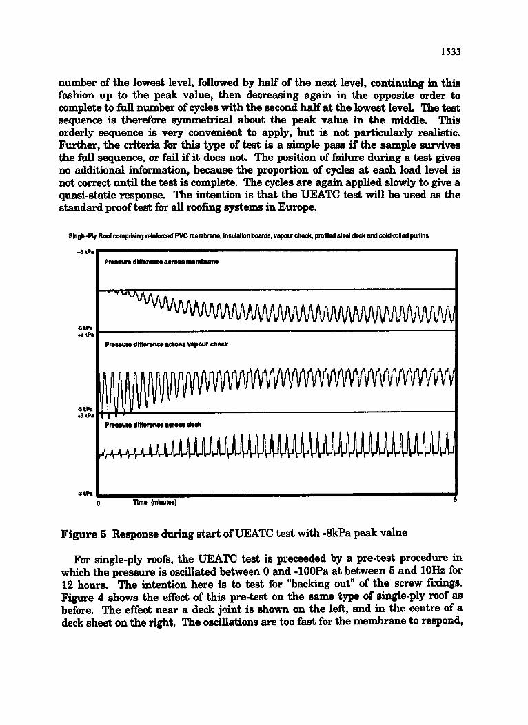
number of the lowest level, followed by half of the next level, continuing in this fashion up to the peak value, then decreasing again in the opposite order to complete to full n-tuber of cycles with the second half at the lowest level. The test sequence is therefore symmetrical about the peak value in the middle. This orderly sequence is very convenient to apply, but is not particularly realistic. Further, the criteria for this type of test is a simple pass if the sample survives the full sequence, or fail if it does not. The position of failure during a test gives no additional information, because the proportion of cycles at each load level is not correct until the test is complete. The cycles are again applied slowly to give a quasi-static response. The intention is that the UEATC test will be used as the standard proof test for all roofing systems in Europe.
Single.Ply Roof comprising reinlorced PVG membrane, insulation boards, vapour check, profiled steel deck and cold-rolled purlins
,.3 kPa Pressure dlfforonce across membrane
.3 kPa ~kPa
Pre~um dlfferen~ across wpour cheek
4 kPa 0 Time (minutes)
Figure 5 Response during start of UEATC test with -8kPa peak value
For single-ply roofs, the UEATC test is preceeded by a pre-test procedure in which the pressure is oscillated between 0 and -100Pa at between 5 and 10Hz for 12 hours. The intention here is to test for "backing out" of the screw fixings. Figure 4 shows the effect of this pre-test on the same type of single-ply roof as before. The effect near a deck joint is shown on the left, and in the centre of a deck sheet on the right. The oscillations are too fast for the membrane to respond,

1534
so they are passed to the vapour check and deck, leaving only the mean value across the membrane. At the deck joint the vapour check takes most of the load, whereas at the deck centre it is transferred to the deck. Note that the vapour check shows the same single-sided response at the deck centre as shown in Figure 3. No fluctuations appear across the main membrane and, if its fixing scews are separate from those holding down the insulation, they will not be exercised as was intended.
Singfo-Ply Roof ooml~sing reinforced PVC membrane, insulall® boards, v~our check, profiled steel deck and e-okl-uroNed purSns
+6kPa
~ k P a +6kPa
Pressure difference i c r o i i mtmbrene
t.~ad Iwelo - - ~ .
Pressure difference across vapour check
i n i ; 0 i I I I I I I I I
I I i I u I I I I I I I ,
I I I I I I I I I I I I I I I I I I I I I I I I I
I I I I I a i i I i i
k?s _ _J i i i I i *0 kPa | ' ' ; I
Pressure dlfferenoe a c r e u deok I i I i I ! I I I I I I I I I I I I I I I
I I I I I I I I I I i I
0 11mo (ml.uloo) 6
Figure 6 Response during middle of UEATC test with -8kPa peak valu#
The main UEATC test is intended to be quasi-static. Figures 5 & 6 show the response of the same single-ply roof system to the beginning and the middle of the main UEATC test sequence. At the beginning, it takes about 30 cycles over 3 minutes to reach equilibrium. Initially, while air is being driven through the vapour check to raise the membrane, the vapour check takes most of the load. Once equilibrium is achieved it is clear that the balance between layers is not the same as for the realistic BRERWULF test in Figure 3. In the middle of the trace, the number of cycles at the higher levels is too small for equilibrium to be reached. Owing to the long time constant, the response conti~,~es *~) increase attar the maximum load and is largest for the final cycle at 90%.

1535
6. CONCLUSIONS
It is clear that, while tests based on a quasi-static assumption are appropriate for the rainscreen overcladding, they are not appropriate for single-ply roof systems, The proportion of the peak applied load in the UEATC test taken by the main membrane is compared with the BRERWULF values in Table 1 and are consistently lower. The UEATC test can be made to replicate the peak load on the membrane given by the BRERWULF test if the applied load is increased by a factor, but this would exaggerate the load the vapour check and deck. This factor will vary with the time constant of the roof, but it is likely that a consistent relationship between the required factor and the n-tuber of cycles to reach equilibri-m could be found• In these tests, the factor would be about 1.25 for the high modulus membrane and about 1.8 for the low modulus membrane.
Single-Ply Rool comprising unreinfcrced PVC membrane, in~utalion boards, vapour check, profiled steel deck and cold-rolled pudins
+6 kPa i
i Pressure dlfforonce across membrane Failure of membrane joint
I
• 6 kPa +5 kPa I
I Pressure dlttereMe e©ross vapour chol,t( !
Pressuredlfferenoe across deck
. . . . . . . . . ,.I ,.;. . . . ; , , . ; , , ,;,. , . . . . . . . . 1 . . . . . . . . . . . . . . . . . . . . • :
I ' I I I I
0 Time (minutes)
Figure 7 Failure of membrane joint during 7-hour storm with -8kPa peak value
However, two major drawbacks of simple cyclic tests will always remain. Firstly, the proportion of the applied load taken by each layer depends on the frequency of the loading: in the simple cyclic test this is a fixed low frequency, whereas in the realistic BRERWULF test the frequency spectrum of the actual wind loads and hence the dynamic response of the roof system are correctly

1536
reproduced. This may lead to an unrealistic mode of failure: for example, in the UEATC test per~)rmed on the system with the low modulus EPDM membrane, the vapour check failed during the test with a -6kPa peak value, whereas the system successfully survived the realistic BRERWULF tests up to -8kPa. Since this failure occurred inside the system, it would have remained unobserved in the tests (and in practice) without the measurements of membrane loading in Table 1, which shows that the proportion of the applied load taken by the membrane rose atter failure to the level expected of the system without a vapour check
Secondly, cyclic tests are pass/fail tests and the position of failure within a test is meaningless. This is not true of the realistic BRERWULF test. Figure 7 shows the results obtained for an unreinforced PVC single-ply roof system which failed by unpeeling a membrane joint bond during a test with a peak value of -8kPa (representing a safety factor in excess of 3). The failure of the bond was observed progressing during the test and the time to failure is indicative of the fatigue life of the system. Further, the progression of the failure must depend on the load history and correct reproduction requires the load cycle content to be correct during this period.
Accordingly, it is suggested that simple cyclic tests are not appropriate for testing single-ply roof systems. The UEATC test will be appropriate and most useful for many forms of roof that have a quasi-static response, but should not be taken as the standard across the full range of roofing systems. A significant proportion of other multi-layer cladding and roofing systems will exhibit non- linear or frequency-dependent characteristics that will require more realistic test sequences.
7. REFERENCES
Cook, N.J., A.P. Keevil & R.K. Stobart 1988. BRERWULF. the Big Bad Wolf. J. Wind Engng. & Indust. Aerodyn. 29, 99-107.
Cook, N.J. 1990. The designer's guide to wind loading of building structures: Part 2 . Static structures. London, Butterworth Scientific.
Harris, R.I. 1990. The propagation of internal pressures in buildings. J. Wind Engng. & lndust. Aerodyn. 34, 169-184.
Holmes, J.D. 1980. Mean and fluctuating pressure induced by wind. In J.E.Cermak (Ed), Wind Engineering: Proceedings of the fifth international conference, Fort Collins, Colorado, 1979. Oxford, Pergamon Press.
Redfearn, D. 1984. A test rig for proof-testing building components against wind loads. BRE Information Paper IP19/84. Garston. Building Research Establishment.
Strutt , J.W. (Baron Rayleigh) 1896. Theory of sound. London: Macmillan. Vickery, B.J. 1986. Gust factors for internal pressures in low rise buildings. J.
Wind Engng. & Indust. Aerodyn. 23, 259-271.