dynamic response of floating substructure of spar-type ... · pdf filedynamic response of...
TRANSCRIPT
Ocean Engineering 72 (2013) 356–364
Contents lists available at ScienceDirect
Ocean Engineering
0029-80http://d
n CorrE-m
journal homepage: www.elsevier.com/locate/oceaneng
Dynamic response of floating substructure of spar-type offshore windturbine with catenary mooring cables
S.H. Jeon a, Y.U. Cho a, M.W. Seo a, J.R. Cho a,b, W.B. Jeong a,n
a School of Mechanical Engineering, Pusan National University, Busan 609-735, Republic of Koreab Research & Development Institute of Midas IT, Gyeonggi-Do 462-807, Republic of Korea
a r t i c l e i n f o
Article history:Received 9 January 2013Accepted 18 July 2013Available online 10 August 2013
Keywords:Floating offshore wind turbineDynamic responseFloating substructureMooring cableWave modelFluid–rigid body interaction
18/$ - see front matter & 2013 Elsevier Ltd. Ax.doi.org/10.1016/j.oceaneng.2013.07.017
esponding author. Tel.: +82 51 510 2377; fax:ail address: [email protected] (W.B. Jeong
a b s t r a c t
The station keeping and the rotational oscillation control are important to secure the dynamic stability ofspar-type floating offshore wind turbine subject to irregular wind and wave excitations. Those are usuallyevaluated in terms of rigid body dynamic response of floating substructure which supports wholeoffshore wind turbine. In this context, this paper addresses the numerical investigation of dynamicresponse of a spar-type hollow cylindrical floating substructure moored by three catenary cables toirregular wave excitation. The upper part of wind turbine above wind tower is simplified as a lumpedmass and the incompressible irregular potential wave flow is generated according to the Pierson–Moskowitz spectrum. The wave-floating substructure and wave-mooring cable interactions are simu-lated by coupling BEM and FEM in the staggered iterative manner. Through the numerical experiments,the time- and frequency-responses of a rigid spar-type hollow cylindrical floating substructure and thetension of mooring cables are investigated with respect to the total length and the connection position ofmooring cables.
& 2013 Elsevier Ltd. All rights reserved.
1. Introduction
Wind turbines are only used to extract the renewable energyfrom the wind, and those were initially designed for installing onland and showed the rapid increase in both the total number ofwind turbines installed and the maximum wind power capacity(Hansen and Hansen, 2007). However, this rapid increase encoun-tered several obstacles such as the substantial environmentalimpact on people living in the vicinity of wind turbines, thelimitation of being high-capacity and making large wind farm.This critical situation naturally turned the attention to the offshoresites, a less restrictive installation place. Offshore wind turbinesare classified largely into two categories, fixed- and floating-typeaccording to how the wind turbine tower is supported. Differingfrom the fixed-type, the floating-type wind turbine is under theconcept design stage because several core technologies are notfully settled down (Karimirad et al., 2011), particularly the main-tenance of dynamic stability against irregular wind, wave andcurrent loads (Faltinsen, 1990).
In order to secure the dynamic stability of floating-type off-shore wind turbine, the station keeping at sea and the rotationaloscillation control becomes critical (Tong, 1998). Because of this
ll rights reserved.
+82 51 514 7640.).
essential requirement, the floating-type offshore wind turbinerequires additional equipments like substructure, mooring linesor tension legs and anchors, when compared to the fixed-type.And, those are classified according to how is generated the right-ing moment or draft control, such as submerged-, TLP (tension-legplatform)- spar-types (Lee, 2008; Jonkman, 2009), and barge-typeFOWT. However, all the types have some things in common fromthe fact that the station keeping and the vertical and rotationaloscillation control of them are secured by a combined use of thebuoyancy force and the tension of mooring lines or tension legs.
In case of spar-type floating wind turbine, the buoyancy forceproduced by a long hollow cylindrical substructure supports thewhole offshore wind turbine and the tension of mooring lineskeeps the station position of spar-type floating substructure. Thepitch and roll stability can to a large extent be maintained by thepitch and roll stiffness of spar-type floating substructure whichincreases in proportional to the metacentric height (i.e., thevertical distance between the metacenter and the center of mass)(Koo et al., 2004) and the relative distance between the centers ofgravity and buoyancy (Karimirad et al., 2011). In addition, it is alsoinfluenced by both the tension magnitude and the connectionposition of mooring lines, and it could be improved further whenpassive tuned liquid damper (TLD) or/and active control usingwater ballast are employed (Lee, 2005; Lee et al., 2006; Colwelland Basu, 2009; Seo et al., 2012). Here, the pitch and roll stiffnessis meant by the pitching and rolling moments required to pitchand roll the substructure by unit angle.
S.H. Jeon et al. / Ocean Engineering 72 (2013) 356–364 357
The dynamic response of spar-type offshore wind turbine towind and wave excitations is usually evaluated in terms of rigidbody degrees of freedom of floating substructure. The stationkeeping referring to the horizontal degrees of freedom, surge andsway are largely influenced by the mooring system, while theother degrees of freedom are mainly affected by the floatingplatform characteristics.
This subject has been studied by experimentally using small-scaleprototypes (Nielsen et al., 2006; Utsunomiya et al., 2010; Goopeeet al., 2012), by analytically/numerically with the simplified windturbine geometry and the analytically derived wind/wave loads(Tracy, 2007; Lee, 2005; Karimirad, 2010; Dodaran and Park, 2012),or by the combined use of CFD, hydro, FSI (fluid-structure interac-tion) or/and MBD (multibody dynamics) codes (Zambrano et al.,2006; Jonkman, 2009; Jonkman and Musial, 2010). In case ofnumerical simulation, 3-D full Navier–Stokes equations are rarelyused because extremely long slender mooring lines not only requirea large simulation domain but cause highly turbulence flow aroundthem. Because of this numerical difficulty, water flow aroundsubstructure and mooring lines is usually assumed to be potentialflow (Ansys, 2012).
The purpose of the current study is to numerically investigatethe dynamic response of spar-type floating substructure to wave-induced excitation. The upper part composed of wind blades, huband nacelle is simplified as a lumped mass, and three catenarymooring cables are considered. Sea water is assumed to bepotential flow by neglecting the viscosity and compressibility,and the time histories of irregular wave are generated using thePierson–Moskowitz spectrum (1964). The wave-floating substruc-ture and wave-mooring cable interactions are simulated by thecoupled BEM–FEM methods in the staggered iterative approach(Cho et al., 2008). Through the numerical experiments, dynamicresponses of cylindrical floating substructure and mooring cablesare investigated with respect to the length and connection posi-tion of mooring cables and to location of the center of mass offloating substructure.
2. Problem description
2.1. Spar-type floating offshore wind turbine
The most important requirement for renewable energies is theefficiency and capacity, and in this regard wind energy draws anintensive attention because of its potential to generate a hugeamount of electricity from plenty of wind around us (Hansen andHansen, 2007). In particular, floating offshore wind turbines arecurrently drawing a worldwide attention because the wind powercapacity and efficiency can be maximized by constructing windfarm with such next generation wind turbines at deep seaproviding stable wind energy. However, for the floating offshorewind turbine, the design of floating substructure becomes acritical subject because it not only supports the whole windturbine system and but also influences the dynamic stability.Currently, most concerns focus on three types of floating sub-structures, barge, tension leg (TLP) and spar types.
A typical spar-type floating offshore wind turbine is repre-sented in Fig. 1, where the whole wind turbine is supported by thebuoyancy force and the amplitude of rotational oscillations couldbe reduced by the bottom weight, tuned liquid damper andhydraulic control. Regarding the dynamic displacement of windturbine which is caused by wind, wave and current loads, onlysurge and sway displacements are counteracted by the mooringlines when a catenary mooring system is adopted while thedisplacements in all DOFs are counteracted by tension lines if aTLP system is adopted (Lefebvre and Collu, 2012). The dynamic
stability of floating-type wind turbine is evaluated in terms ofthree translational motions (i.e., surge, sway and heave) and threerotational motions (i.e., pitch, roll and yaw). These six componentsof the rigid body motion are coupled to each other, and the surgeand pitch motions are the most significant factors in the evalua-tion of the dynamic stability of wind turbine. The dynamic stabilityof floating-type wind turbine is influenced by gust, wave andcurrent, so most research efforts have been focused on the effectsof such aero and hydro excitations.
In general, the pitch stiffness is proportional to the metacentricheight, composed of different elements, not only to the distancebetween the center of buoyancy (CB) and the center of gravity (CG)(Karimirad et al., 2011). Furthermore, if the CG is above the CB,then the more distance theses points are the less stable in thefloating structure. As well as, the connection position and tensionof mooring lines do also influence the pitch stiffness of the floatingsubstructure. Among available mooring systems, catenary mooringcomposed of fabric ropes and steel chains is widely adoptedbecause of its topological simplicity and cost effectiveness (Wu,1995). Catenary mooring cables are anchored at seabed andconnected to the floating substructure, and they have smallflexural stiffness so that external loads are resisted by the in-linetension. Here, the external loads include the self weight,the hydrodynamic drag forces in the normal, tangential andbi-normal directions, and the added inertia force stemming fromsurrounding sea water (Vaz and Patel, 2000). The extremely smalldiameter of catenary cables easily causes large-eddy turbulentflow around cables, so that the equilibrium configuration is usuallycomputed by the geometrically nonlinear cable dynamics.
2.2. Wave model
A wave spectrum is the distribution of wave energy in functionof frequency which describes the total energy transmitted by awave-field at a specific time. As one of the simplest spectrumswhich are widely used, the Pierson–Moskowitz (Pierson andMoskowitz, 1964) is an empirical relationship between the energydistribution and frequency of irregular wave at sea. It is suitablefor decomposing a sea-state into several sinusoidal wave compo-nents. It is based upon the assumption that wave reaches theequilibrium state, known as a fully developed sea wave, if windblows steadily for a long time over a large area. The energy densitySðωÞ ðm2=HzÞ of wave in the Pierson–Moskowitz spectrum isdefined by (Pillai and Prasad, 2000)
SðωÞ ¼ π32Hs
T2z
!21ω5 exp �π3
2Tzω
� �4 !
ð1Þ
where, ω ðrad=sÞ is the wave frequency, Hs ðmÞ the significantwave height, and Tz ðsÞ the zero crossing period. Fig. 2(a) shows atypical energy density distribution when the significant waveheight Hs and the zero crossing period Tz are 1:0 m and 10 s,respectively.
For a given wave spectrum, the time history of irregular wavecan be generated by linear superposition of harmonic wavecomponents (Kim, 2001), as represented in Fig. 2(b). Then, thewave height ηðx; tÞ is expressed by
ηðx; tÞ ¼ 12
∑N
n ¼ 1An cos ðknx�2πf nt þ ϕnÞ ð2Þ
with the wave number kn, the wave frequency f n, the waveamplitude An and the phase angle ϕn. And, the relationshipbetween the energy density SðωjÞ and the wave amplitude Aj for

Fig. 1. Representation: (a) spar-type floating offshore wind turbine subject to irregular wave and (b) 6-DOF rigid body motion (CB: center of buoyancy and CG: center ofgravity).
0 0.05 0.1 0.15 0.2 0.25 0.3 0.35 0.40
0.05
0.1
0.15
0.2
0.25
Frequency ω (rad/sec)
Ener
gy d
ensi
ty S
(ω) (
m2 /H
z)
Fig. 2. Pierson–Moskowitz wave spectrum: (a) a typical energy density spectrum (Hs ¼ 1:0 m and Tz ¼ 10 s) and (b) wave profile.
S.H. Jeon et al. / Ocean Engineering 72 (2013) 356–364358
the j-th wave component is given by (Faltinsen, 1990)
A2j
2¼ SðωjÞ
ωmax�ωmin
Nð3Þ
In which, the frequency range is divided by the number of N, andthe maximum and minimum frequencies ωmax ¼ 0:1 Hz andωmin ¼ 0:01 Hz are determined from the Pierson–Moskowitzspectrum.
3. Fluid–rigid body interaction problem
Referring to Fig. 3(a), let ΩFAℜ3 be a semi-infinite unboundedflow domain with the boundary ∂ΩF ¼ SF [ SB [ ΓI and V denotesa continuous triple-vector water velocity field, where SF ; SB and ΓI
indicate the free surface, seabed and flow-structure interfacerespectively. Water is assumed to be inviscid and incompressibleand water flow is irrotational so that there exists a velocitypotential function ϕðx; tÞ satisfyingϕðx; tÞ : V¼∇ϕ ð4ÞThe velocity potential function ϕðx; tÞ is defined by
ϕðx; tÞ ¼ ∑6
j ¼ 1ϕj þ ϕw þ ϕd ð5Þ
with ϕj due to the rigid body motion of structure, ϕw due toundisturbed incoming wave and ϕd due to diffraction of theundisturbed incoming wave, respectively. Then, the flow field isgoverned by the continuity equation
∇2ϕ¼ 0; in ΩF � ð0; t̂� ð6Þand the boundary conditions given by
∂ϕ∂n
¼ _uUn; on ΓI ð7Þ
g∂ϕ∂z
þ ∂2ϕ∂t2
¼ 0; on SF ð8Þ
∂ϕ∂z
¼ 0; on SB ð9Þ
with t̂ being the time period of observation, u the displacementvector of the rigid body, g the gravity acceleration, n the outwardunit vector normal to the structure boundary. Eq. (8) is a unifiedfree surface condition derived from the linearized dynamic andkinematic conditions on SF by neglecting the surface tension (Choand Song, 2001; Cho et al., 2005). In addition, the potential functionsatisfies the radiation condition: φ-0 as r-1 at the far field.
The substructure occupying the material domain ΩSAℜ3 withthe boundary ∂ΩS ¼ ΓD [ ΓN [ ΓI is assumed to be a rigid body.By denoting fd; θg be its rigid body translation and rotation at the

Fig. 3. (a) A rigid floating body moored by catenary cables in irregular wave and (b) forces acting on the cable element dℓ.
Table 1Major specifications of spar-type floating offshore wind turbine.
Items Values
Upper part Total mass of blades, hub and nacelle 1:766� 105 kgHeights of nacelle and tower 3.2 m, 65.0 mDiameters of tower (top and bottom) 3:5 m; 4:5 mTotal mass of tower 1:70� 105 kg
Lower part Height and diameter of substructure 65:0 m; 8:0 mTotal mass of substructure 2:684� 106 kgCenter of buoyancy and center of mass 32:5 m; 42:5 m
S.H. Jeon et al. / Ocean Engineering 72 (2013) 356–364 359
center of mass, the dynamic motion of the substructure isgoverned by the conservation of linear and angular momentumsði¼ x; y; zÞm €di þ ci _di þ kidi ¼ Fi; in ΩS � ð0; t̂� ð10Þ
Iθij €θj þ cθi _θi þ kθi θi ¼Mi; in ΩS � ð0; t̂� ð11Þ
and the initial conditions given by
f _d; _θgt ¼ 0 ¼ f _d; _θ0g; fd; θgt ¼ 0 ¼ fd0; θ0g ð12ÞIn which m; ci; ki; cθi and kθi denote the total mass and thedamping and stiffness coefficients for the translational and rota-tional degrees of freedom, respectively. Meanwhile, Iθij indicate themass moments of inertia with respect to the center of mass, and Fand M are the external force and moment vectors, respectively,which are calculated by
F¼ZΓI
pn ds ð13Þ
M ¼ZΓI
pr� n ds ð14Þ
Here, p and r are the hydrodynamic pressure and the positionvector from the center of mass, respectively.
Meanwhile, catenary mooring cable of length L is a slenderflexible structure subject to hydrodynamic pressure, self weight,inertia force and drag force. Referring to Fig. 3(b), the nonlineardifferential equations of motion (Goodman and Breslin, 1976;Aamo and Fossen, 2000) for the differential cable element dℓ aregoverned by the equilibrium equations in translation and rotation,
ðmc þmaÞ∂ _uc
∂t¼ ∂T c
∂sþ ð1þ γÞFc ð15Þ
∂Mc
∂s¼�rt � ð1þ γÞTc ð16Þ
and the compatibility equation
∂ _uc
∂ s¼ ∂
∂ tðð1þ γÞrtÞ ð17Þ
with the boundary conditions given by
_uc ¼ 0; ϑc ¼ ϑBc at s¼ 0 ðat seabedÞ ð18Þ
_uc ¼ _dP ; ϑc ¼ ϑPc at s¼ L ðat connecting pointÞ ð19ÞIn which, mc indicates the mass per unit arc length, ma the addedmass of water, _uc the velocity vector, s the arc length of unstressedcable, and γ is the engineering strain. In addition, rt is the vectortangent to the cable center line, Mc the resultant internal moment,and Fc the external loading per unit arc length due to the selfweight ρcg, and Fn, Fτ and Fq the normal, tangential and binormal
drag forces (Morison et al., 1950). Here, the unit vector q in the bi-normal direction is defined by q¼ _uc � τ=j _uc � τj with τ being thetangential unit vector. Eq. (16) and the associated boundaryconditions are excluded when the flexural stiffness of catenarycables is neglected.
The potential flow governed by Eqs. (6)–(9) is interpolated bythe boundary element method while the dynamic motions of therigid floating substructure and mooring cables are approximatedby the finite element method. For the rigid body dynamic motionanalysis, only the surface of rigid floating substructure is discretizedwith 2-D finite elements and each mooring line is divided into afinite number of line elements. A two-step predictor–correctormethod (Cong, 1996; Kim and Kim, 2001) is used for the timeintegration of the equations of motion. The Euler–Lagrange-typecoupling method is employed to deal with the interaction betweenthe rigid body structure motion and the water flow, and it with thelapse of time is numerically implemented in a staggered iterativemanner (Sigrist and Abouri, 2006; Cho et al., 2008). The hydro-dynamic pressure of water flow acts as the external force andmoment for both the floating substructure and mooring cables, andthen the rigid body movement of floating substructure relocates theflow-structure interface. This staggered computation iterates up tothe preset time period of observation.
4. Parametric sensitivity study
A spar-type floating offshore wind turbine with three equalcatenary mooring cables is taken for the parametric numericalexperiments of dynamic responses of the cylindrical floatingsubstructure and mooring cables. The geometry dimensions andtotal masses of the major components are recorded in Table 1.Referring to Fig. 4(a), three rotor blades, hub and nacelle assemblyare simplified as a lumped mass, and the whole rigid bodycomposed of the top lumped mass, tower and substructure isdiscretized with the total of 2,920 10-node hexahedron elements.The center of buoyancy (CB) and the center of mass (CM) are

Fig. 4. A coupled fluid–rigid body interaction model: (a) FEM mesh of rigid floating wind turbine and Euler fluid domain and (b) alignment of three equal catenary lines.
Fig. 5. Time responses of the rigid body motion of spar-type floating substructure (L¼ 290 m, connected to CB): (a) surge and (b) pitch.
S.H. Jeon et al. / Ocean Engineering 72 (2013) 356–364360
measured from the free surface of water and the relative verticaldistance between two centers is set by 10:0 m.
The section dimensions of the water pool are set by 500�500 m2 and the depth from seabed is set by 200 m, respectively.The free surface coincides with the interface between tower andfloating substructure, and the significant wave height Hs and thezero crossing period Tz in the Pierson–Moskowitz spectrum are setby 1:0 m and 10 s respectively. The water depth is chosen from thefact that floating offshore wind turbines are typically installed atsea of water depth 100–300 m, and the section dimensions of thewater pool are chosen so as to sufficiently cover three mooringcables by considering the CPU time required for the numericalsimulation. Two parameters Hs and Tz in the Pierson–Moskowiczspectrum are chosen referring to the sea state between 2 and 3(Wayman et al., 2006). The total length of all three catenarymooring cables is taken variable and the angles between twoadjacent catenary cables are 1201, while the horizontal distance dcbetween anchor and the substructure is always kept by 200 m.Each mooring cable is discretized into 100 uniform elements andfixed at seabed and connected to the substructure by the node-to-node connection. The cross sectional area Ac , the mass per unitlength γc , the stiffness EA and the maximum allowable tensionTmaxc are 0:02 m2, 90 kg=m, 1:0� 109 N and 1:0� 107 N respec-
tively, and the hydrodynamic drag coefficient CD is set by 0.025(Wilson, 1960).
Three equal catenary mooring lines are aligned as representedin Fig. 4(b) where the wave direction opposites to the x-direction.The directions of six components of the rigid body motion offloating offshore wind turbine follow the convention shown inFig. 1(b). The fluid–rigid body interaction simulation was carriedout by the commercial FEM software ANSYS AQWA (Ansys, 2012).The time and frequency responses of rigid floating substructure
and the cable tension are parametrically investigated with respectto the total length and connection position of three mooringcables.
4.1. To the total length of mooring cables
Figs. 5 and 6 represent the time and frequency responses ofsurge and pitch motions when three mooring cables with the totallength L of 290 m are connected to the center of buoyancy.Considering the cable installation position at the center of buoy-ancy and the horizontal distance dc of anchor, there is always afraction of the mooring cables laying on the seabed when the totalcable length is longer than 260 m. And, such a fraction does nothave any influence on the cable tension because its weight iscounteracted by the seabed reaction. The angle between theseabed and mooring cable at anchor point is not zero and theanchor experiences vertical forces only when the total suspendedcable length is equal to its total length, but this case cannot bemodeled by the hypotheses of a catenary mooring quasi-staticapproach which is adopted for the current study. The surge motionat the center of mass shows the sine-wave-like time history withthe peak amplitude of 2:1 m. Meanwhile, the substructure shows asmall pitch motion with the peak amplitude near 0.51 at thebeginning and then it exhibits a beating-like pitch motion with thepeak amplitude greater than 2.21, implying that the rotationalinertia of floating substructure is remarkable. One can see twoapparent surge resonance frequencies from Fig. 5(a), the lowestone of 0:0029 Hz and the other one of 0:0324 Hz, where the latteris identical to the first pitch resonance frequency, showing thecoupling between surge and pitch motions. Thus, it has beenconfirmed from the frequency response that the natural
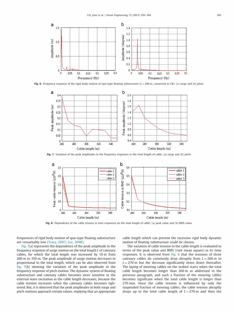
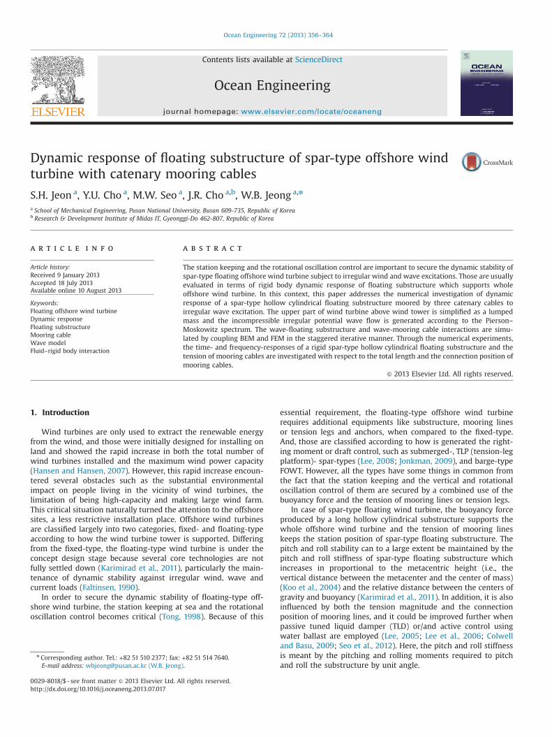
Fig. 6. Frequency response of the rigid body motion of spar-type floating substructure (L¼ 290 m, connected to CB): (a) surge and (b) pitch.
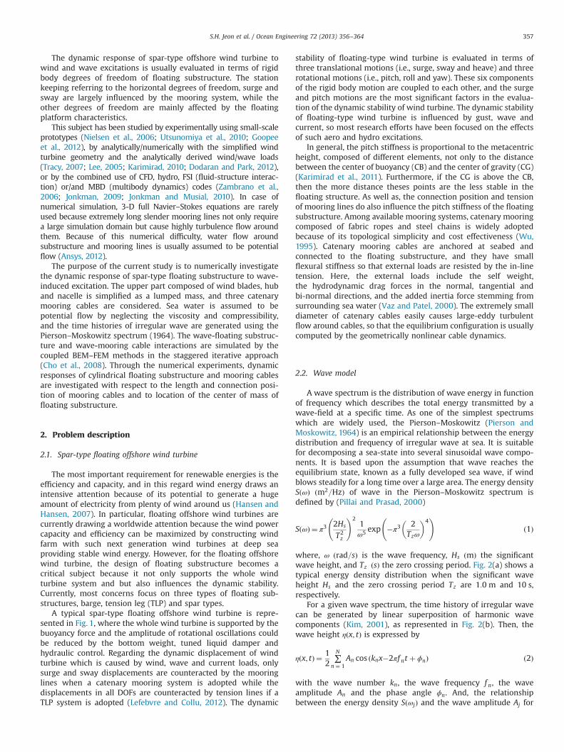
Fig. 7. Variation of the peak amplitudes in the frequency responses to the total length of cable: (a) surge and (b) pitch.
Fig. 8. Dependence of the cable tension in time responses on the total length of cable: (a) peak value and (b) RMS value.
S.H. Jeon et al. / Ocean Engineering 72 (2013) 356–364 361
frequencies of rigid body motion of spar-type floating substructureare remarkably low (Tracy, 2007; Lee, 2008).
Fig. 7(a) represents the dependence of the peak amplitude in thefrequency response of surge motion on the total length L of catenarycables, for which the total length was increased by 10 m from260 m to 350 m. The peak amplitude of surge motion decreases inproportional to the total length, which can be also observed fromFig. 7(b) showing the variation of the peak amplitude in thefrequency response of pitch motion. The dynamic system of floatingsubstructure and catenary cables becomes more sensitive to theexternal wave excitation as the cable length decreases, because thecable tension increases when the catenary cables becomes tigh-tened. But, it is observed that the peak amplitudes in both surge andpitch motions approach certain values, implying that an appropriate
cable length which can prevent the excessive rigid body dynamicmotion of floating substructure could be chosen.
The variation of cable tension to the cable length is evaluated interms of the peak value and RMS (root mean square) in its timeresponses. It is observed from Fig. 8 that the tensions of threecatenary cables do commonly drop abruptly from L¼ 260 m toL¼ 270 m but the decrease significantly slows down thereafter.The laying of mooring cables on the seabed starts when the totalcable length becomes longer than 260 m as addressed in theprevious paragraph, and such a fraction of the mooring cablesbecomes significant when the total cable length is longer than270 mm. Since the cable tension is influenced by only thesuspended fraction of mooring cables, the cable tension abruptlydrops up to the total cable length of L¼ 270 m and then the
S.H. Jeon et al. / Ocean Engineering 72 (2013) 356–364362
influence of the total cable length on the cable tension becomesinsignificant. This tendency is consistent well with the variation ofpeak amplitudes shown in Fig. 7 to the cable length, where thepeak surge amplitude steeply decreases at such a critical intervalof cable length and vise versa for the peak pitch amplitude.
Cables 1 and 3 exhibit almost the same cable tension butcable 2 produces the cable tension smaller than cables 1 and 3 atthe critical interval of cable length, but three cables show almostthe same magnitude beyond such a critical length interval.Considering the relative orientation of three mooring cables tothe wave direction, cables 1 and 2 experience the similarremarkable extension and relaxation but cable 3 does notexperience the remarkable extension. Thus, cable 3 shows therelatively lower tension than cables 1 and 2 in the criticalinterval of cable length. Beyond such a critical interval, thesignificant decrease in both the suspended fraction of mooringcables and the surge and pitch amplitudes lead to almost thesame magnitude in three cable tensions. As well as, such adifference in the cable tensions of three cables becomes negli-gible when the cable tension is measured in RMS, becausecables 1 and 2 experience larger fluctuation in time responsesof cable tension than cable 3.
4.2. To the connection position of mooring cables
Next, the effects of the cable connection position on the surgeand pitch motions of the spar-type floating substructure and thecable tension are investigated. The total cable length is set byL¼ 300 m where the peak surge amplitude is lowest. The con-nection position is measured from the free surface of sea water as
Fig. 9. The connection position of mooring cables.
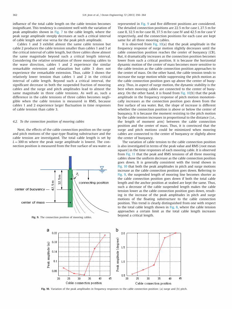
Fig. 10. Variation of the peak amplitudes in frequency response
represented in Fig. 9 and five different positions are considered.The detailed connection positions are 22:5 m for case I, 27:5 m forcase II, 32:5 m for case III, 37:5 m for case IV and 42:5 m for case Vrespectively, and the connection positions for each case are keptsame for all three mooring cables.
It is observed from Fig. 10(a) that the peak amplitude in thefrequency response of surge motion slightly decreases until thecable connection position reaches the center of buoyancy (CB).But, it dramatically increases as the connection position becomeslower from such a critical position. It is because the horizontaldynamic motion of the center of mass becomes more sensitive tothe cable tension as the cable connection position approaches tothe center of mass. On the other hand, the cable tension tends toincrease the surge motion while suppressing the pitch motion asthe cable connection position goes up above the center of buoy-ancy. Thus, in aspect of surge motion, the dynamic stability is thebest when mooring cables are connected to the center of buoy-ancy. On the other hand, it is found from Fig. 10(b) that the peakamplitude in the frequency response of pitch motion monotoni-cally increases as the connection position goes down from thefree surface of sea water. But, the slope of increase is differentwhether the connection position is above or below the center ofbuoyancy. It is because the moment resisting to the pitch motionby the cable tension increases in proportional to the distance (i.e.,the length of moment arm) between the cable connectionposition and the center of mass. Thus, it is convinced that thesurge and pitch motions could be minimized when mooringcables are connected to the center of buoyancy or slightly abovethe center of buoyancy.
The variation of cable tension to the cable connection positionis also investigated in terms of the peak value and RMS (root meansquare) in the time responses of each mooring cable. It is observedfrom Fig. 11 that the peak and RMS tensions of all three mooringcables show the uniform decrease as the cable connection positiongoes down. It is generally consistent with the trend shown inFig. 10 that both the peak amplitudes in pitch and surge motionsincrease as the cable connection position goes down. Referring toFig. 9, the suspended length of mooring line becomes shorter asthe cable connection position goes down if both the total cablelength and the anchor position at seabed are kept the same. Thus,such a decrease of the cable suspended length makes the cabletension lower as the cable connection position goes down, result-ing in the increase of the peak amplitudes in pitch and surgemotions of the floating substructure to the cable connectionposition. This trend is clearly distinguished from one with respectto the total cable length shown in Fig. 8, where the cable tensionapproaches a certain limit as the total cable length increasesbeyond a critical length.
s to the cable connection position: (a) surge and (b) pitch.
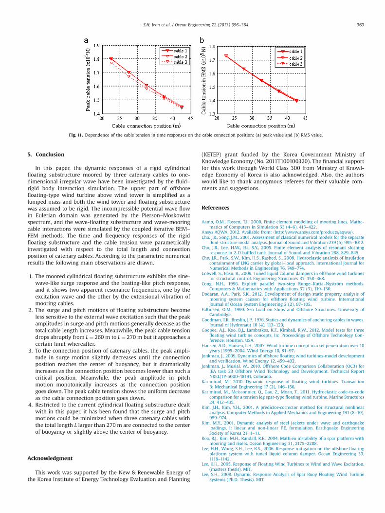
Fig. 11. Dependence of the cable tension in time responses on the cable connection position: (a) peak value and (b) RMS value.
S.H. Jeon et al. / Ocean Engineering 72 (2013) 356–364 363
5. Conclusion
In this paper, the dynamic responses of a rigid cylindricalfloating substructure moored by three catenary cables to one-dimensional irregular wave have been investigated by the fluid–rigid body interaction simulation. The upper part of offshorefloating-type wind turbine above wind tower is simplified as alumped mass and both the wind tower and floating substructurewas assumed to be rigid. The incompressible potential wave flowin Eulerian domain was generated by the Pierson–Moskowitzspectrum, and the wave-floating substructure and wave-mooringcable interactions were simulated by the coupled iterative BEM–
FEM methods. The time and frequency responses of the rigidfloating substructure and the cable tension were parametricallyinvestigated with respect to the total length and connectionposition of catenary cables. According to the parametric numericalresults the following main observations are drawn.
1.
The moored cylindrical floating substructure exhibits the sine-wave-like surge response and the beating-like pitch response,and it shows two apparent resonance frequencies, one by theexcitation wave and the other by the extensional vibration ofmooring cables.2.
The surge and pitch motions of floating substructure becomeless sensitive to the external wave excitation such that the peakamplitudes in surge and pitch motions generally decease as thetotal cable length increases. Meanwhile, the peak cable tensiondrops abruptly from L¼ 260 m to L¼ 270 m but it approaches acertain limit whereafter.3.
To the connection position of catenary cables, the peak ampli-tude in surge motion slightly decreases until the connectionposition reaches the center of buoyancy, but it dramaticallyincreases as the connection position becomes lower than such acritical position. Meanwhile, the peak amplitude in pitchmotion monotonically increases as the connection positiongoes down. The peak cable tension shows the uniform decreaseas the cable connection position goes down.4.
Restricted to the current cylindrical floating substructure dealtwith in this paper, it has been found that the surge and pitchmotions could be minimized when three catenary cables withthe total length L larger than 270 m are connected to the centerof buoyancy or slightly above the center of buoyancy.Acknowledgment
This work was supported by the New & Renewable Energy ofthe Korea Institute of Energy Technology Evaluation and Planning
(KETEP) grant funded by the Korea Government Ministry ofKnowledge Economy (No. 2011T100100320). The financial supportfor this work through World Class 300 from Ministry of Knowl-edge Economy of Korea is also acknowledged. Also, the authorswould like to thank anonymous referees for their valuable com-ments and suggestions.
References
Aamo, O.M., Fossen, T.I., 2000. Finite element modeling of mooring lines. Mathe-matics of Computers in Simulation 53 (4–6), 415–422.
Ansys AQWA, 2012. Available from: ⟨http://www.ansys.com/products/aqwa/⟩.Cho, J.R., Song, J.M., 2001. Assessment of classical numerical models for the separate
fluid-structure modal analysis. Journal of Sound and Vibration 239 (5), 995–1012.Cho, J.R., Lee, H.W., Ha, S.Y., 2005. Finite element analysis of resonant sloshing
response in 2-D baffled tank. Journal of Sound and Vibration 288, 829–845.Cho, J.R., Park, S.W., Kim, H.S., Rashed, S., 2008. Hydroelastic analysis of insulation
containment of LNG carrier by global–local approach. International Journal forNumerical Methods in Engineering 76, 749–774.
Colwell, S., Basu, B., 2009. Tuned liquid column dampers in offshore wind turbinesfor structural control. Engineering Structures 31, 358–368.
Cong, N.H., 1996. Explicit parallel two-step Runge–Kutta–Nyström methods.Computers & Mathematics with Applications 32 (3), 119–130.
Dodaran, A.A., Park, S.K., 2012. Development of design static property analysis ofmooring system caisson for offshore floating wind turbine. InternationalJournal of Ocean System Engineering 2 (2), 97–105.
Faltinsen, O.M., 1990. Sea Load on Ships and Offshore Structures. University ofCambridge.
Goodman, T.R., Breslin, J.P., 1976. Statics and dynamics of anchoring cables in waves.Journal of Hydronaut 10 (4), 113–120.
Goopee, A.J., Koo, B.J., Lambrakos, K.F., Kimball, R.W., 2012. Model tests for threefloating wind turbine concepts. In: Proceedings of Offshore Technology Con-ference, Houston, USA.
Hansen, A.D., Hansen, L.H., 2007. Wind turbine concept market penetration over 10years (1995–2004. Wind Energy 10, 81–97.
Jonkman, J., 2009. Dynamics of offshore floating wind turbines-model developmentand verification. Wind Energy 12, 459–492.
Jonkman, J., Musial, W., 2010. Offshore Code Comparison Collaboration (OC3) forIEA task 23 Offshore Wind Technology and Development. Technical ReportNREL/TP-5000-48191, Colorado.
Karimirad, M., 2010. Dynamic response of floating wind turbines. TransactionB: Mechanical Engineering 17 (2), 146–156.
Karimirad, M., Meissonnier, Q., Gao, Z., Moan, T., 2011. Hydroelastic code-to-codecomparison for a tension leg spar-type floating wind turbine. Marine Structures24, 412–435.
Kim, J.H., Kim, Y.H., 2001. A predictor-corrector method for structural nonlinearanalysis. Computer Methods in Applied Mechanics and Engineering 191 (8–10),959–974.
Kim, M.Y., 2001. Dynamic analysis of steel jackets under wave and earthquakeloadings, I: linear and non-linear F.E. formulation. Earthquake EngineeringSociety of Korea 21, 1–11.
Koo, B.J., Kim, M.H., Randall, R.E., 2004. Mathieu instability of a spar platform withmooring and risers. Ocean Engineering 31, 2175–2208.
Lee, H.H., Wong, S.H., Lee, R.S., 2006. Response mitigation on the offshore floatingplatform system with tuned liquid column damper. Ocean Engineering 33,1118–1142.
Lee, K.H., 2005. Response of Floating Wind Turbines to Wind and Wave Excitation,(masters thesis). MIT.
Lee, S.H., 2008. Dynamic Response Analysis of Spar Buoy Floating Wind TurbineSystems (Ph.D. Thesis). MIT.
S.H. Jeon et al. / Ocean Engineering 72 (2013) 356–364364
Lefebvre, S., Collu, M., 2012. Preliminary design of a floating support structure for a5 MW offshore wind turbine. Ocean Engineering 40, 15–26.
Morison, J.R., O'Brien, M.P., Johnson, J.W., Schaaf, S.A., 1950. The force exerted bysurface waves on piles. Petroleum Transaction 189, 149–157.
Nielsen, F.G., Hanson, T.D., Skaare, B., 2006. Integrated dynamic analysis of floatingoffshore wind turbines. In: Proceedings of 25th International Conference onOffshore Mechanics and Arctiv Engineering (OMAE2006) 1, 671–679.
Pierson, W.J., Moskowitz, J.L., 1964. A proposed spectral form fully developed windseas on similarity theory of S.A. Kitaigorodskii. Journal of Geophysical Research69 (24), 5181–5190.
Pillai, T.M.M., Prasad, A.M., 2000. Fatigue reliability analysis in time domainfor inspection strategy of fixed offshore structures. Ocean Engineering 27,167–186.
Seo, M.W., Cho, Y.U., Park, W.G., Jeong, W.B., Cho, J.R. Study on the sloshingcharacteristics of annular cylindrical tuned liquid damper for spar-type floatingoffshore wind turbine. Structural Engineering Mechanics, (in preparation).
Sigrist, J.F., Abouri, D., Numerical simulation of a non-linear coupled fluid-structureproblemwith implicit and explicit coupling procedure. In: Proceedings of ASMEPressure Vessel and Piping Division Conference, Vancouver, Canada, 23–27.
Tong, K.C., 1998. Technical and economic aspects of a floating offshore windfarm. Journal of Wind Engineering and Industrial Aerodynamics 74-76,399–410.
Tracy, C., 2007. Parametric Design of Floating Wind Turbines, (maters thesis). MIT.Utsunomiya, T., Matsukuma, H., Minoura, S., 2010. On sea experiment of a hybrid
SPAR for floating offshore wind turbine using 1/10 scale model. In: Proceedingsof ASME 2010 29th International Conference on Ocean, Offshore and ArticEngineering, Shanghai, China.
Vaz, M.A., Patel, M.H., 2000. Three-dimensional behavior of elastic marine cables insheared currents. Applied Ocean Research 22, 45–53.
Wayman, E.N., Sclavounos, P.D., Butterfield, S., Konkman, J., Musial, W., 2006.Coupled dynamic modeling of floating wind turbine systems. In: Proceedings ofthe Offshore Technology Conference, OTC Paper Number 18287, Houston, Texas.
Wilson, B.W., 1960. Characteristics of Anchor cables in Uniform Ocean Currents.Texas A&M Report No. 204-1.
Wu, S., 1995. Adaptive dynamic relaxation technique for static analysis of catenarymooring. Marine Structures 8, 585–599.
Zambrano, T., MacCready, T., Kiceniuk, T., Goddier, D.G., Cermelli, C.A., 2006.Dynamic modeling of deepwater offshore wind turbine structures in gulf ofMexico storm conditions. In: Proceedings of 25th International Conference onOffshore Mechanics and Arctic Engineering, Hamburg, Germany.