dynamic response of beam and frame …ethesis.nitrkl.ac.in/6201/1/212me1277-`18.pdfnational...
TRANSCRIPT

“DYNAMIC RESPONSE OF BEAM AND FRAME
STRUCTURE SUBJECTED TO MOVING LOAD” A thesis submitted in the partial fulfillment of the requirements
for the degree of
MASTER OF TECHNOLOGY
IN
MECHANICAL ENGINEERING
(Specialization: Machine Design and Analysis)
Submitted by
JITENDRA NAIK (ROLL NO: 212ME1277)
DEPARTMENT OF MECHANICAL ENGINEERING
NATIONAL INSTITUTE OF TECHNOLOGY
ROURKELA-769008, INDIA
MAY-2014

“DYNAMIC RESPONSE OF BEAM AND FRAME
STRUCTURE SUBJECTED TO MOVING LOAD” A thesis submitted in the partial fulfillment of the requirements
for the degree of
MASTER OF TECHNOLOGY
IN
MECHANICAL ENGINEERING
(Specialization: Machine Design and Analysis)
Submitted by
JITENDRA NAIK (ROLL NO: 212ME1277)
Under the guidance of
Prof. R. K. BEHERA
DEPARTMENT OF MECHANICAL ENGINEERING
NATIONAL INSTITUTE OF TECHNOLOGY
ROURKELA-769008, INDIA
MAY-2014

NATIONAL INSTITUTE OF TECHNOLOGY
ROURKELA
CERTIFICATE
This is to certify that the thesis entitled, “DYNAMIC RESPONSE OF BEAM
AND FRAME STRUCTURE SUBJECTED TO MOVING LOAD”
submitted by Mr.JITENDRA NAIK (212ME1277) in partial fulfillment of the
requirements for the award of Master Of Technology degree in Mechanical
Engineering with specialization in Machine Design and Analysis at the
National Institute of Technology, Rourkela (India) is an authentic work carried
out by him under my supervision and guidance.
To the best of my knowledge, the matter embodied in the thesis has not
been submitted to any other University / Institute for the award of any Degree or
Diploma.
Date: Prof. R.K.BEHERA
Assoc. Professor
Department of Mechanical Engineering,
National Institute of Technology,
Rourkela-769008.

ACKNOWLEDGEMENT
Successful completion of this work will never be one man’s task. It requires
hard work in right direction. There are many who have helped to make my
experience as a student a rewarding one.
In particular, I express my gratitude and deep regards to my thesis guide Prof.
R. K. Behera, for his valuable guidance, constant encouragement and kind co-
operation throughout period of work which has been instrumental in the success
of thesis.
I also express my sincere gratitude to Prof. K. P. Maity, Head of the
Department, Mechanical Engineering, for providing valuable departmental
facilities.
Finally, I would like to thank my fellow post-graduate students.
JITENDRA NAIK
Roll No: 212ME1277
Department Of Mechanical Engineering
National Institute of Technology
Rourkela-769008

Contents
Title Page No
Abstract i
List of figures ii
List of tables iii
Nomenclatures iv
Chapter 1 ...................................................................................... 1
Introduction .............................................................................................................1
Chapter 2 ...................................................................................... 2
Literature Survey .....................................................................................................2
Chapter 3 ...................................................................................... 9
3. Dynamic Response Of Structure ...........................................................................9
3.1 Beam Structure ...................................................................................................9
3.2 Frame Structure ................................................................................................ 10
Chapter 4 .................................................................................... 11
4. The Finite Element Method ................................................................................ 11
4.1 General Principle Of Finite Element Analysis: ................................................. 11
4.2 General Steps Of The Finite Element Method ................................................... 12
4.3 Applications Of The Finite Element Method .................................................... 15
4.4 Limitations Of The Finite Element Method ...................................................... 15
Chapter 5 .................................................................................... 16
5. Finite Element Analysis Of Beam Element ......................................................... 16
5.1 Analysis Of Frame Element .............................................................................. 20

Chapter 6 .................................................................................... 23
Mathematical Formulation ..................................................................................... 23
6.1 Equation Of Motion For Forced Vibration System ............................................ 23
6.2 Expressions For External Force Vector: ............................................................ 23
6.3 Moving Load Problem ...................................................................................... 27
Solution Of Equation Of Motion ............................................................................ 30
Application Of Moving Load ................................................................................. 30
Chapter 7 .................................................................................... 30
7.1 Numerical Results ............................................................................................ 31
Table 2: Natural Frequency Of Beam With Different Boundary Conditions: .......... 31
Table 3: Natural Frequency Of Frame Element For Clamped-Clamped Condition. . 31
Chapter 8 .................................................................................... 38
Discussion .............................................................................................................. 38
Chapter 9 .................................................................................... 40
9.1 Conclusions ...................................................................................................... 40
9.2 Scope For Future Work .................................................................................... 41
Rferences .................................................................................... 42

i
ABSTRACT
In this work the dynamic response of beam and the frame structure is studied.
Analysis is done with the help of finite element analysis method. Beam structure is
divided into ten elements for constituting the mass and stiffness matrices. Frame
structure consists of two columns of equal geometry. Each column is divided into ten
elements having the same property as beam. Euler Bernoulli beam theory is assumed for
the analysis of these structures. Three different boundary conditions are taken such as
clamped-clamped, pinned-pinned and clamped-pinned for dynamic analysis. Two
degree of freedom is considered for beam and the effect of moment and inertia is
neglected for moving load problem. A concentrated load moving at constant speed over
the beam. Comparison between static and dynamic displacement is done for different
boundary conditions. MATLAB programs are developed to get the response and the
results were validated with previous research work. The study of dynamic response is
having a great importance in the field of mechanical, civil and aerospace engineering. A
dynamic load varies with time and space for example railway track, roadways, bridges,
cranes, rope ways are some examples of structures subjected to dynamic load. The beam
and the columns of the frame structure are divided into ten elements each. Mid point
displacement is studied for concentrated point load moving at constant speed. The
obtain results are collected and response graph are plotted for different boundary
conditions. The results are compared and conclusions are drawn.
Keywords: beam, frame, Moving mass, dynamic response, Finite element method.

ii
LIST OF FIGURES
Fig 3.1 : Schematic diagram of bridge frame structure
Fig.5.1 : Beam element
Fig.5.2 : Nodal representation of frame structure
Fig.5.3 : Modelling of column 1 and column 2 of the frame structure
Fig.6.1 : Nodal forces acting on beam element under moving load
Fig.6.2 : A point load moving along beam from node 1 to node n
Fig.7.1 : Mid point displacement of clamped-clamped beam of load moving
with velocity 30 m/s.
Fig.7.2 : Mid point displacement of pinned-pinned beam of load moving with velocity
45 m/s
Fig.7.3 : Mid point displacement of clamped-pinned beam of load moving with
velocity 30 m/s.
Fig 7.4 : Mid point displacement of clamped-clamped frame of load moving with
velocity 33 m/s
Fig 7.6 : Dynamic displacement of mid-point of pinned-pinned beam versus the
position of moving load for different speeds.
Fig 7.7 : Dynamic displacement of mid-point of clamped-clamped beam versus
the position of moving load for different speeds.
Fig 7.8 : Comparison of midpoint displacement of the column 1 of the frame
structure with stiffness k1 and k2 (v= 5m/s).
Fig 7.9 : Comparison of midpoint displacement of the column 1 of the frame
structure with stiffness k1 and k2 (v= 45m/s).
Fig 7.10 : Effect of stiffness on the mid-point displacement of beam of frame

iii
LIST OF TABLES
Table 1 : Geometry and properties of beam.
Table 2 : Natural frequency of beam with different boundary conditions.
Table 3 : Natural frequency of frame having stiffness k1 and k2 with different
boundary conditions.
Table 4 : Dynamic magnification factors at the mid-point of the beam for
different velocities.
Table 5 : Dynamic magnification factors at the mid-point of the beam for
different velocities.

iv
NOMENCLATURE
E : modulus of elasticity(GPa)
I : moment of inertia
L : total length of the beam
: density of the beam
A : area of cross section of beam
l : length of beam element
x, y : axial co-ordinates
x : position of the moving load from left end of the beam
iN : shape function
y(x, t) : transverse displacement
M : overall mass matrix of beam
K : overall stiffness matrix of beam
T : transformation matrix
k1, k2 : spring stiffness
t : time
V : velocity of moving load
m : mass
: total time taken by moving load along the beam
: natural frequency
t : time interval
P : moving concentrated load
: time period of ith natural frequency
iT
Nit, Rourkela Page 1
Chapter 1
INTRODUCTION
Moving load is unpreventable in structural dynamics. Many research have been done on
this problem during past years. Till the middle of the 19th century the effect of dynamic
load was unknown. The collapsed of Stephenson’s bridge over Dee Chester river in
London in 1947 attracted many researchers to study the response of structure subjected
to moving load. Many researchers took interest in study the response of dynamic
structure like Railway Bridge and Highway Bridge because it is the most common
practical problem related to dynamic response. In all the dynamic problems, beam type
structure is the most common type of structure used in the field of civil, mechanical and
aerospace engineering. Bridge vehicle interaction is the most common problem in
moving load analysis and it’s been the vast area of research. If the speed of the vehicle
is very slow, it could not be treated as moving load problem because at low speed it
behaves as a static load condition. This problem can be solved by traditional ways. If
the vehicle is moving at constant speed then it will be treated as moving load problem.
This problem can be solve by mathematical and computational analysis. In the past
years dynamic load problem are about the highway and railway bridge excited by
moving vehicle. Almost all engineering structure is subjected to time and space varying
load. Due to traffic intensity many factors arises which need to study the structure in
many aspects. In this thesis the simple beam is investigated with different boundary
condition. In addition to that the problem is extended to study the response of moving
load on frame structure. Effect on the response with additional stiffness is investigated.
The effect of inertia and moment are neglected for moving load analysis. Finite element
method is approached to study the response of beam and frame structure.
Nit, Rourkela Page 2
Chapter 2
LITERATURE SURVEY
Dynamic response of beam is an essential topic of research in structural dynamics.
Beam is a most common type of structure used in the field of aerospace engineering,
mechanical engineering and civil engineering. Many of these structures subjected to
dynamic load. Beam with moving load is a special topic of research in structural
dynamics as compared to other load because it subjected to time and space varying load.
Many approaches have been taken by scientists to solve the dynamic problem, hence a
lots of literature exists
Thambiratnam & Zhuge [1] investigated a simple model to study the behavior of simply
supported beam. The model was supported on an elastic foundation. In the first case the
beam was analyze for static condition and the results obtain from the analysis were
applied for the analysis of railway track structure. Same model was tested for free
vibration condition. The problem is formulated for the beam of any length and it is very
useful for the analysis of railway track structure. They prolonged their experiment to the
analysis of beam having elastic foundation subjected to moving load. All these
experiment give rise an approach to for free vibration, static and dynamic analysis of
beam supported on an elastic foundation. This procedure simplified the complexity of
the problem because the axial effect and the effect of the change in beam properties,
beam length be easily accommodated in this problem. The effect of stiffness on
foundation was investigated, travelling speed and beam length on dynamic
magnification factor.

Nit, Rourkela Page 3
Serdar hugul [2] investigated the dynamic response of systems subjected to moving
load. The system includes the beam structure with different boundary condition and the
frame structure. He solved the dynamic problem by two numerical method i.e. the Finite
element method and the Newmark integration method. For the analysis of forced
vibration Newmark integration is employed. Beam is assumed as Euler Bernoulli for
finite element analysis. He studied the response for fixed-fixed, pined-pined and fixed-
pined boundary condition. The study is also carried out for the column of the frame
structure. The problem is extended to show the effect on response of the beam structure
of various parameter such as velocity of the moving load, spring stiffness, viscous
damping and additional stiffness at the conjunction point of beam and column.
MATLAB and ANSYS program have been developed and the results were validated.
Results are obtained for various alpha values (non-dimensional parameter) and
compared for different boundary conditions. Both static and dynamic deflections are
experimented. For static case deflection is measured when the load was at the midpoint.
It was found that the maximum dynamic displacement occurs at the mid-point of the
pinned-pinned beam which is expectable. The additional stiffness increases the rigidity
of the frame structure alternately the mode shape shifts up. Damping is also considered
and it gives negligible effect on the beam and the frame structure. It is concluded that
the longer beam has the smaller natural frequency similarly the longer column has lower
natural frequency.
Olsson [3] investigated the dynamic response of beam subjected to a load moving with a
constant speed. The vibration response of a simply supported beam with and without
elastic foundation to a moving single point load is analyzed performing the finite element
vibration analysis and presented analytical and finite element solutions. Olsson

Nit, Rourkela Page 4
investigated taking three approaches i.e. Formation of loading functions, Modal analysis
and Transient analysis. In the first case he consider static
Wang & Lin [4] investigated the dynamic response of a multi-span Timoshenko frame
structure due to moving load. They used modal analysis technique to study the response.
Zibdeh & Hilal [5] investigated the dynamic behavior of beam structure with different
boundary condition traversed by moving load also analyzed the beam structure of
different boundary conditions traversed by a moving load. They analyzed the beam
structure for different types of motions such as accelerating, decelerating and constant
velocity .Also the showed the effect of motion and damping for different boundary
condition.
M. Dehestani et. al. [6] Recent development researchers material and constructional
technology greatly effected by sudden change in weight of elements of structures. In such
conditions inertia effect of moving bodies will not be avoidable. Study of inertia effect
helps to investigate response of bridge structures and many engineering application
structures that are moving with high speed such as machining processes. They presented
analytical and numerical results to find out the response due to moving load. They have
considered all the boundary conditions to investigate the best design specifications. Also
shown the effect of coriolis component of acceleration related to moving mass of the
system. The influence of speed on different boundary conditions is also stated. It
concluded that the speed and the inertia of moving mass has direct influence on the
response of the structure for all boundary conditions.

Nit, Rourkela Page 5
Law & Zhu [7] studied the vibration of a damped reinforced concrete beam structure
under moving load. They modeled as moving system having four degree of freedom .The
moving mass system has linear suspension tyre flexibility. This experiment is carried out
for continuous Euler Bernoulli beam simply supported at both the ends. They validate the
analytical solution with the experimental results. In their further study they presented
indirect approach to to study the response by using a device called structural health
monitoring which sensed the response. This technique is applied to bridge-vehicle
interaction field. This device processes the information about response of bridge structure
to which define the state of bridge.
Karganovin et. al. [8] investigated the response of Timoshenko beam. The beam structure
is supported by visco-elastic foundation which subjected to distributed moving load.
They presented theoretical analysis to study the response. Effect of frequency and the
velocity of dynamic load on displacement is studied. They shown that with the increase
of frequency and velocity of moving load on maximum displacement firstly increases
and then decreases .
T. Karttunen et. al. [9] studied the dynamic behavior of an elastic cylinder cover using a
1D Pasternak-type foundation model with damping. Moving point load is applied on
cylinder cover, which is taken to represent a load resultant due to rolling contact. the
natural frequencies, vibration response, wave dispersion relation, total strain energy and
dissipation power of the cover are obtained by Analytical expressions . The calculated
natural frequencies and modes by the 1D approach are validated to those given by a 2D
plane strain finite element model and a satisfactory result is obtained. The critical load
speed in the cover is obtained for the un-damped analytical model at a resonance
condition. The critical speed is the minimum phase velocity of the waves in the cover.
The speeds decrease when damping is included.

Nit, Rourkela Page 6
Bergman et. al.[10] studied the damaged Euler Bernoulli beam subjected to moving
mass. They validated the result both theoretically and experimentally.
Michaltos et. al. [11] investigated the dynamic response of a simply supported uniform
beam under a moving load of constant magnitude and velocity. The effect of the mass of
the moving load and its velocity and of other parameters is verified using a series
solution for the dynamic deflection. A variety of numerical results are obtained to draw
important conclusions for the purpose of structural design.
Mehri et al. [12] studied the dynamic response of uniform beams with different boundary
conditions subjected to moving load assuming Euler-Bernoulli beam theory. Effects of
velocity of mass for different boundary conditions and some other parameters are studied
Using dynamic green function and some of the numerical results are compared with the
given literatures. An exact and direct modeling technique is formulated for forming beam
structures with different boundary conditions, subjected to mass moving at constant
speed. The effect of variation in the speed parameters results was given in graphical and
tabular form to analyze the dynamic response of beam.
Hamada [13] used double Laplace transform to find a solution for a beam with damping
under the action of a mass less load moving at constant speed. He investigated the
response damped Euler–Bernoulli uniform beam supported at both the ends. He obtained
close solution for dynamic response which is useful for computation of beam stresses.
Analysis of Forced vibration is done using double power series method and the
coefficient of the series is obtained by the use of Bernoulli polynomials.

Nit, Rourkela Page 7
Ting et al [14] studied the response of both the beam and the moving mass for dynamic
response. He formed an algorithm to study the response including various boundary
conditions, for that Initial conditions are necessary to make the problem simpler. He
illustrated an example to verify the Results obtained by theoretically and experimentally
are well comparable.
P.K.Chatterjee et. al. [15] studied the multi-span continuous Euler Bernoulli beam under
dynamic load. They considered the effect of vehicle and bridge surface interaction, also
consider the torsion of the bridge structure due to eccentricity of moving vehicle.
Iterative procedure is applied to study the response for each time step. A continuous
approach is utilized to determine the Eigen functions of the bridge. The method is used to
investigate the influence of parameters that are important on the response of the bridge
structure. To find the response of continuous beam a continuous approach has been
taken. The results were obtained with respect to time and the non-linear effect of moving
load for the dynamic response.
Ismail Gerdemeli et. al.[16] investigated the dynamic response of overhead crane beams.
The beam was assumed as an Euler Bernoulli beam. Computerized analysis was done in
SAP 2000. The response of the crane beam depends on mass and the velocity of the load.
The natural frequency of the system changes as the moving load changing its position
with time. Depending on the position of the moving mass the system vibration varies.
Trethway et. al.[17] investigated the elastic beam subjected to moving load. The
governing equation for the finite element analysis is derived by finite element method
which is solved by Runge-Kutta method. This method is much efficient to solve any
tome dependent dynamic system motion also gives the best approach to solve the
equation with complex boundary condition. They consider the moving system of two
foot height having damping and stiffness. In this paper various types of moving load

Nit, Rourkela Page 8
have been presented. They study the dynamic load system having different height
moving at constant velocity along the beam. This model well succeed so this method
implemented to real field application. Using this technique high speed drilling machine
structure is investigated. Effect of various factors like speed, inertia, number of moving
load on a single system also considered in their further study. The moving mass inertia
has a great effect on the response of structure attributed to dynamic load.
In this thesis dynamic response of beam and frame structure subjected to moving load
is studied using finite element method and analytical method. Aim of this thesis is to
show the static and dynamic result and compare the results, effect of velocity on the
response of the beam and the column of the frame structure is studied.
Nit, Rourkela Page 9
Chapter 3
3. DYNAMIC RESPONSE OF STRUCTURE
In the middle of the nineteenth century the resonant transverse vibration of highway and
railway bridge structure alarmed the engineers to study the dynamic behavior of
structure. Collapsed of Stephenson’s bridge in London in 1947 attracted the intention of
design engineers to research structure subjected to moving load. The intention was to
investigate the response of structure under dynamic load and safety of design against
dynamic forces , moment and deformation due to moving load. Vibration of structure
arises due to motion of vehicle, earth quake, flow of stream and winds. There’s various
factors need to consider for design safety purpose such as Mass of the moving body and
the structure, Inertia of moving mass Twisting of structure due eccentric load.
3.1 BEAM STRUCTURE
Beams are the description of engineering structures. Frames of machines, automobiles
and other mechanical structure are composed of beam that are specially designed. All
these structures are analyzed in the similar way as beam. Beam is an element that carries
vertical and horizontal loads. These loads can be static or dynamic. Static load is due to
the external bodies resting on beam and the dynamic load is the result of moving body,
due to blow of wind or an earthquake. These loads are transmitted to its supports. Beams
are defined by their geometry and the type of material. Now a days usually reinforced
concrete, steel or wooden beams are used in constructions.

Nit, Rourkela Page 10
Beam can be differentiated into three criteria i.e. based on geometry, equilibrium
conditions and the types of supports. According to the type of supports beam can be of
following types
1. Simply supported beam: Simply supported beam is the simplest structural element in
existence. It has pinned support at one end and roller support at the other end. It
undergoes shearing or bending, depending on the externally applied load.
2. Cantilever beam: It has fixed support at one end and free at other end.
3. Overhanging beam: The span of the beam extended beyond its supports are called
overhanging beam. It is combined feature of simply supported and cantilever.
4. Continuous beam: This type of beam has more than two supports over its length.
5. Fixed beam: In this type of beam both the ends of the beam are fixed.
3.2 FRAME STRUCTURE
Frame structures are the combination of beam and columns. The loads carried by beam
of the frame structure are distributed to its column. Columns and slab generally used to
support against applied loads, moments and deformation. A rigid frame structure is
made up of linear elements, typically beams and columns that are connected to one
another at their ends that do not allow any relative rotation to occur between the attached
members, although the joints themselves may rotate as a unit.
Figure 3.1 Schematic diagram of bridge frame structure

Nit, Rourkela Page 11
Chapter 4
4. THE FINITE ELEMENT METHOD
It is a simple and effective method to analyze the behavior of regular or
irregular, continuous structure for general loadings. In FEM the problem is solved by
discretizing the continuous physical structure into simple geometric element. The
discrete element is used for the analysis of whole structure. The complex structure is
discretized into finite number of elements which are interconnected. The point at
which the discrete element are joined is known as node. Each element consist of two
nodes. Degrees of freedom are applied at the node for the finite element analysis.
In mathematics, it is a numerical technique use to find the approximate
solution of boundary value problems. Complex equation of large domain can easily
solve by connecting sub domain equation called as finite element. Computational tool
is use to perform the analysis.
4.1 GENERAL PRINCIPLE OF FINITE ELEMENT
ANALYSIS:
Discretizing the whole structure into number elements, the element should
be of known geometry for the convenience of mathematical formulation. It has several
advantage like the complex shape can be represented so the properties of dissimilar
material can be included and local effect can be easily captured. Each element
represented by sets of equation to the original problem. Total solution is obtained by
globalizing the each element for final calculation. Best results can be obtained by
maximizing the number of elements.
Nit, Rourkela Page 12
4.2 General steps of the Finite Element Method
The following general steps discussed below are for structural analysis case.
1. Discretization and choosing element types:
This step includes division of geometry into an equivalent set of finite elements
with associated nodes and selecting the best suitable element which resembles the actual
physical behavior of the given system to be analyzed. Engineer needs to focus in the
matters of selecting the number elements, variation in size and type of elements. For
getting best results it is advisable to choose as small elements as possible. One of the
major tasks of the engineer is the selection of the appropriate element for a particular
problem.
2. Select a Primary variable function:
This step involves selecting a primary variable (displacement) function within each
element. The function is defined within the element using the nodal values of the
element. Polynomial functions are generally used because they are easy to work within
finite element formulation. In case of two dimensional elements, the primary variable
function is function of the coordinates in its plane. The functions are expressed in terms
of the nodal unknowns.
3. Define relations:
The relations among stresses, strains and displacements are essential for obtaining
the equations for each finite element. In the case of one –dimensional deformation, say,
in the x direction, we have strain related to displacement u by
dx
dux

Nit, Rourkela Page 13
for small strain cases. The definition of material behavior is also important in obtaining
acceptable results.
4. Extraction of the element stiffness Matrix and Equations:
The element stiffness matrix and equations are deriving by using the following
methods.
Direct Equilibrium Method
According to this method, the stiffness matrix and element equations relating
nodal forces to nodal displacements are obtained using force equilibrium conditions for a
basic element, along with force or deformation relationships. This method can easily
adaptable to line or one-dimensional elements.
Work or Energy Methods
For the extraction of the stiffness and equations for two and three-dimensional
elements, the application of work or energy methods are very friendly. The principle of
minimum potential energy, the principle of virtual work methods used for derivation of
element equations.
Generally, for elastic materials the principle of minimum potential energy is suitable
whereas the principle of virtual work can be adopted for any other material.
Methods of Weighted Residuals
The methods of weighted residuals are useful for developing the element
equations particularly popular Galerkin’s method. This methods yield the same results as
the energy methods wherever the energy methods are applicable. They are especially
useful when a functional such as energy method is not readily applicable.

Nit, Rourkela Page 14
5. Assembling the Element equations and Apply boundary conditions:
In this step, the equilibrium equations of nodes that are obtained in previous step
are combined into the global nodal equilibrium equations. One more direct method of
superposition, whose basis is nodal force equilibrium, can be used to obtain the global
equations.
The global equation can be written in matrix form as
Where represents the Force vector, is the total stiffness matrix is the vector of
generalised displacements.
At this stage, the global stiffness matrix is a singular matrix because its determinant is
equal to zero. To remove this we need to call upon certain boundary conditions in order
to avoid to the movement of the structure as rigid body.
6. Solve for the primary unknowns:
These general equations can be solved for the primary unknowns by using an elimination
method or an iterative method. The primary variables are different for various problems.
In case of the structural problem the unknown primary variable is displacement.
7. Solve for secondary unknowns:
In this step secondary unknowns are determined by using the displacement
equations which are already obtained from previous step. Commonly strain and stress,
Nit, Rourkela Page 15
shear force and moments are secondary unknowns for structural problem, are determined
by using mathematical techniques.
8. Interpret the results:
The results obtained in previous step need to analyze for use in the design or
analysis process. For better design and to avoid the failure of the structure it is important
to determine the locations in the structure where large deformations and stresses is occur.
Postprocessor computer programs help the user to interpret the results by displaying them
in graphical form.
4.3 APPLICATIONS OF THE FINITE ELEMENT METHOD
It is an effective tool to analyze both structural and non-structural problems. Structural
analysis include vibration, buckling and stress analysis the stress concentration problems
associated with fillet, holes and other changes in the geometry of the body. Non-
structural analysis include fluid flow, transfer of heat and the distribution of a electric or
magnetic potential. It can be applied to solve biomechanical engineering problems such
as analyses of human spine, skull, hip joints, heart and eye etc.
4.4 LIMITATIONS OF THE FINITE ELEMENT METHOD
In spite of many advantages it has certain drawbacks also which are as follows
Stress values depend on the size of mesh.
In some cases the approximations used may not provide accurate results.
For vibration and stability problems the cost of analysis by FEA is prohibitive.

Nit, Rourkela Page 16
Chapter 5
5. FINITE ELEMENT ANALYSIS OF BEAM ELEMENT
Beam element:
A uniform cross section beam element is considerd to form the finite element matrices as
shown in figure given below. Euler Bernoulli theory is assumed for analysis of beam. In
the figure given below represents the element of the beam having length l and x represent
the length at any instant of time from the starting of node to the point at which the load is
acting.
In the figure 5.1 E, ρ and I are the modulus of elasticity, density and
constant moment of inertia of the beam respectively. For each node two degree of
freedom is considered for finite element analysis.
Fig 5.1 Beam element
Strain energy and the kinetic energy of the beam element is considered to formulate
constituting the finite element matrices.

Nit, Rourkela Page 17
Strain energy for the considered single element is give in the expression below:
dxx
yEIES
l
0
2
2
2
21.. (1)
Where E and I are the modulus of elasticity and the inertia of the beam. Kinetic energy of
a single element is given as
dxt
yAKE
L
2
0
)(2
(2)
For the transverse displacements a cubic function, y(x,t) has assumed,
3
3
2
210),( xaxaxaatxy (3)
Where 0a , 1a , 2a , 3a are the functions of “ t” which can be obtained by applying boundary
conditions at the corresponding nodes, Rao(1995)[19] represented the shape function as
given below
32
1 231)(
l
x
l
xxN (3.1)
32
2 2)(
l
xl
l
xlxxN (3.2)
32
3 23)(
l
x
l
xxN (3.3)
32
4 )(
l
xl
l
xlxN (3.4)
Applying boundary condition on the transverse displacement cubic function
3
3
2
210),( xaxaxaatxy (4)
At x=0, 01 ay 11 ay
At x= l, 3
3
2
2102 lalalaay 2
3212 32 lalaay

Nit, Rourkela Page 18
The above solution can be represented in the matrix form
3
2
1
0
2
32
2
2
1
1
3210
1
0010
0001
a
a
a
a
ll
lll
y
y
y
y
Which can be written as
a C =y (4.1)
Or y C =a-1
(4.2)
We know from the equation ( 4)
yCx
a
a
a
a
xxx
3
2
1
0
321a x =y (4.3)
yCxt
y1
and
t
y
t
y
t
yT
2
2
(4.4)
dxyCxxx
x
x
xyCAEK
Tl
132
3
2
1
0
1
1
2
1..
(5)
Solving the above equation the mass matrix can be obtained as follow:
22
22
422313
221561354
313422
135422156
420
llll
ll
llll
ll
ALM
(6)

Nit, Rourkela Page 19
From equation (1) strain energy given an as follows:
dxx
yEIES
l
0
2
2
2
21..
twice derivative of equation (4.3) will give acceleration as
yCxx
y 1
2
2
6200
(7)
yCx
l
CyEIES
lTT 1
0
6200
6
2
0
0
2
1..
(8)
Equation (8) give the stiffness matrix as follows :
22
22
3
4626
612612
2646
612612
llll
ll
llll
ll
l
EIK (9)
Equation 6 and 9 are the mass and stiffness matrix of a single beam element. In this
analysis beam structure is constitute of 10 elements, so overall mass and stiffness
matrices can be formed by assembling 10 element.

Nit, Rourkela Page 20
5.1 ANALYSIS OF FRAME ELEMENT
For finite element analysis of frame element displacement is assumed to be linear for
longitudinal vibration along the axial direction.
)()(),( tftetxu
Applying initial conditions on the above displacement equation the corresponding shape
function for the frame element can be obtained as given below.(Rao,1995)
l
xN 15 (10)
l
xN 6 (11)
For the beam element two degrees of freedom is considered for each node. Bending and
torsion effect on the frame element is neglected.
A transformation matrix is used to form the element mass matrix and
the element stiffness matrices of the frame. Frame constitute of two columns and a beam.
The beam and each column is constitute of ten elements of equal size. Transformation
matrix is multiplied with the mass and the stiffness matrices of the beam element to
constitute the overall mass and the stiffness for the frame structure. Transformation
matrix is different for both the columns. Transformation matrix is given as follows
cossin00
sincos00
00cossin
00sinsincos
T
And the overall mass and the stiffness can be formed as ]][[][][ TKTK T (12)
and the mass matrices can be formed as ]][[][][ TMTM T (13)

Nit, Rourkela Page 21
Fig. 5.2 nodal representation of frame structure
The frame structure is discrete into equal size thirty element for finite element analysis as
shown in the above figure. The above structure consist 31 nodes. Node 1 to 10 represents
column 1, node 11 to 21 represents the beam over which the load moves and the node 22
to 31 represents column 2.

Nit, Rourkela Page 22
Modeling of the frame is given below. In the transformation matrix the equal to 90
degree for column 1 and 270 degree for the column 2.
Fig 5.3 Modeling of Column 1 and column 2

Nit, Rourkela Page 23
Chapter 6
MATHEMATICAL FORMULATION
6.1 EQUATION OF MOTION FOR FORCED VIBRATION
SYSTEM
Equation of motion for multi degree of freedom system is given as
)()()()( tFtuKtuCtuM (14)
In the above equation )(tu is the nodal displacement vector, [M] and [K] are the
overall mass and stiffness matrices of the beam structure. {F (t)} is the external force
vector.
6.2 EXPRESSIONS FOR EXTERNAL FORCE VECTOR:
The external force vector can be represented by equivalent nodal forces. According to
Clough and Penzien [18] for three degree of freedom system the external force vector
takes the following form:
Fig 6.1 nodal forces acting on beam element
)(tF = }0).......()()()()()(....0{ )(
6
)(
5
)(
4
)(
3
)(
2
)(
1 tftftftftftf ssssss (14a)

Nit, Rourkela Page 24
In the fig )()()( )(
3
)(
2
)(
1 tftftf sss and )()()( )(
6
)(
5
)(
4 tftftf sss are the nodal forces at node s and
s+1 respectively. )(
1
sf and )(
4
sf are the nodal forces along x-axis, )(
2
sf )(
5
sf are the forces
along y-axis and )(
3
sf )(
6
sf are the rotation about the z-axis on the corresponding nodes.
In this study a two degree of system is consider so the axial nodal forces along )(
1
sf and
)(
4
sf are taken to be zero.
)(tF = )(tf s
)(tf s= Ttftftftf )()()()( 6532
=P{N}
TNNNNN 4321
Where 4321 NNNN are the shape functions. According to (Rao,1995) [19] shape functions
are represented as given below.
32
1 231 N
lN )2( 32
2
32
3 23 N
lN )( 32
4
l
x
It should be noted that “ l ” is the length of the beam element and “ x ” is the distance of
moving point load along the element from the moving end to the point of application as
shown in the figure (6.1). The moving load can be expressed by applying forces and
moments which are the function of time to the entire nodes of the finite element model.

Nit, Rourkela Page 25
6.2(a) A MOVING POINT LOAD
Fig 6.2 a point load moving from node 1 to node n
In this analysis the moment is not taken into consideration. As shown in fig(6.2), a
concentrated force P along the beam from node 1 to n with a velocity V. the beam is
composed of n-1 elements. Considering m time step with time interval t the total time
or maximum time is given by
tmt max
Ty
k
yyyy
i FFFFF ]......[}{ 321 (14b)
Where i represent the node number which varies from 0 to k.
Taking initial condition
At time t = 0
Assuming the moving mass is stationary and acceleration zero at node 1 we may obtain
PF y }{ 1
At time t(t 0)
1}{ PNF y
s
31}{ PNF y
s
Nit, Rourkela Page 26
For i = 1 to k, )1,( ssi
0}{ y
iF
Where i represent the node number which varies from 0 to k.
At any time trt (r =1 to m) then the position of the moving point load is given by
tVrtx p )( ; so at any time the element number over which the load is acting can be
found out from 1)(
l
txs
p , that numerical value of l
txp )( be in integer .
The shape function of node s and s+1 is obtain by the following expression:
32
1 231 N
32
3 23 N
Where l
lstx p )1()(
Noting that )(tx p is the variable distance between the moving load from the left end of
the ‘s’th element. Putting above instantaneous forces the overall external force vector can
be obtain by the equation given as
Ty
k
yyyy
i FFFFF ]......[}{ 321

Nit, Rourkela Page 27
6.3 MOVING LOAD PROBLEM
For normal mode analysis procedure, the displacement at any node is given by
)}(]{[)}({ tqtu (15)
)}({ tq is the nodal displacement vector and ][ is the mode shape matrix which
consist of n independent nodal vectors as given below.
][ = }]...{}.........}{}{}{}{[{ 54321 n
][ consist of information about horizontal, vertical and rotational deformation. The
differentiating Eq. (15) velocity and acceleration vector can be obtained as
)}(]{[)}({ tqtu (16)
)}(]{[)}({ tqtu (17)
Neglecting damping and substituting the values of Eq.(15), (16) and (17) into equation
(14) it is obtained.
)()()( tftqktqm nnnnn (18)
}]{[ n
T
nn Mm
}]{[ n
T
nn Kk
tfn ( )= )}({ tFT
n
Rearranging the equation Eq. (18)
)()()( tqktftqm nnnnn (18a)
Nit, Rourkela Page 28
n
nnn
nm
tqktftq
)()()(
n
nnnn
nm
tqmtftq
)()()(
2 (19)
Neglecting damping
n
nnnn
nm
tqmtftq
)()()(
2 (20)
Inserting the value of eq.(20) in the Eq.(17) )}({ tu gives the acceleration along
transverse direction. For element “s” the point between node “s” and “s+1” the vertical
acceleration can be found out by linear interpolation.[18]
l
tatalstxtata
sy
sms
ym
y ))()()()1()(()()( 1
(21)
)(ta sy
is the acceleration of (3(s+1)+2) th element which can be obtain from )}({ tu as
given by equation (17).
At time t=0
0)( ta sy
,
0)}({ tq ,
0)}({ tq
then )}({ tq is determined by solving equation (20). Hence the value of acceleration is
obtained from equation (21). The value of )}({ tq , )}({ tq is found out from equation
(17a) by numerical simulation. By substituting the value of )}({ tq in the equation (15)
gives the dynamic response of structure. By solving following the above procedure the

Nit, Rourkela Page 29
new values of )(ta sy
, )}({ tq and )}({ tq is obtained, these values are taken as initial
value for next calculation.
NODAL DISPLACEMENT
The nodal displacement of structure is obtained by linear interpolation [20]
l
twtwlstxww
y
s
y
smy
s
))()()()1()(( 1 (22)
Where y
sw and )(1 tw y
s are the )}({ tu of (3(s-1)+1)th and (3s+2)th element given by
equation (15)

Nit, Rourkela Page 30
SOLUTION OF EQUATION OF MOTION
Table 1: Result obtain for Natural frequency of the beam by taking following
properties and geometry.
Length(L) In meter
Area(A=b x w) In meter
Density( )
Kg/m^3
Modulus of elasticity(E) in G Pa
1 .01 x .01 7860 210
Material is assumed isotropic. The same properties are considered for analysis of frame
structure. To know the effect due to change in stiffness on the response of the frame
structure two different stiffness considered such as k1=60000 N/m and k2=400000 N/m.
APPLICATION OF MOVING LOAD
The transverse point load P is moving with uniform velocity, ( /LV ) along the beam.
Where is the total time taken by moving load over beam having length L. time taken to
reach “i” th node is Vxii / ,where ix is the location of ith node from starting point of
moving load. A constant load P=150 N is taken.
Chapter 7

Nit, Rourkela Page 31
7.1 NUMERICAL RESULTS
Table 2: Natural frequency of beam with different boundary conditions:
Sl.no.
Clamped-Clamped
Natural frequency
(Hz)
Pinned-Pinned
Natural frequency
(Hz)
Clamped-pinned
Natural frequency
(Hz)
MATLAB MATLAB MATLAB
1 53.134021 23.43854 36.61583
2 146.49908 93.76356 118.6771
3 287.40531 211.0582 247.7498
4 475.88014 375.6354 424.2475
5 713.06762 588.2723 649.1062
6 1000.8781 850.4827 924.0469
Table 3: Natural frequency of frame element for clamped-clamped condition.
Sl.no. (Frame without stiffness)
Natural frequency
(Hz)
(For k1=60000)
Natural frequency
(Hz)
(For k2=400000)
Natural frequency
(Hz)
MATLAB MATLAB MATLAB
1 6.617595 13.8009 14.66242
2 24.71361 44.1372 52.48354
3 53.13402 53.6639 60.53828
4 54.12708 101.0558 118.2718
5 94.50837 145.4388 146.9696
6 146.4991 212.5705 221.8313

Nit, Rourkela Page 32
Figure 7.1 Mid point displacement of clamped-clamped beam of load moving with
velocity 30 m/s.
Figure 7.2 Mid point displacement of pinned-pinned beam of load moving with
velocity 45 m/s

Nit, Rourkela Page 33
Figure 7.3 mid point displacement of clamped-pinned beam of load moving with
velocity 30 m/s.
Figure 7.4 mid point displacement of clamped-clamped frame of load moving with
velocity 33 m/s

Nit, Rourkela Page 34
Figure 7.5 dynamic displacement of mid-point of clamped-clamped beam versus the
position of moving load for different speeds.
Figure 7.6 dynamic displacement of mid-point of pinned-pinned beam versus the
position of moving load for different speeds.

Nit, Rourkela Page 35
Figure 7.7 dynamic displacement of mid-point of clamped-clamped beam versus the
position of moving load for different speeds.
Figure 7.8 Comparison of midpoint displacement of the column 1 of the frame
structure with stiffness k1=60000 and k2=400000 (v= 5m/s).
Nit, Rourkela Page 36
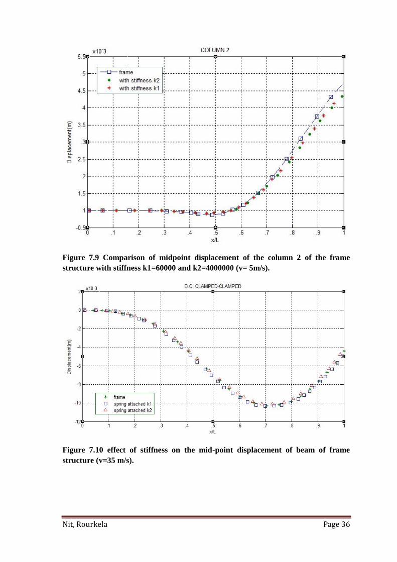
Figure 7.9 Comparison of midpoint displacement of the column 2 of the frame
structure with stiffness k1=60000 and k2=4000000 (v= 5m/s).
Figure 7.10 effect of stiffness on the mid-point displacement of beam of frame
structure (v=35 m/s).

Nit, Rourkela Page 37
Dynamic magnification factors of Beam for different velocities.
Velocity(m/s) 5 10 15 20 25 30 35 40 45 50
Clamped-
Clamped 1 0.988 1.034 1.091 1.296 1.520 1.532 1.576 1.595 1.612
Pinned-Pinned 1.051 1.089 1.123 1.051 1.247 1.403 1.549 1.612 1.677 1.713
Clamped-
Pinned 1.017 1.042 1.079 1.033 1.216 1.354 1.435 1.465 1.596 1.642
Table 4 dynamic magnification factors at the mid-point of the beam for different
velocities.
Table 5 dynamic magnification factors at the mid-point of the beam for different
velocities.
Dynamic magnification factors of Beam for different velocities.
Velocity(m/s) 50 55 60 65 70 75 80 85 90 100
Clamped-
Clamped 1.645 1.656 1.499 1.576 1.533 1.481 1.443 1.401 1.367 1.316
Pinned-Pinned 1.711 1.726 1.722 1.709 1.690 1.678 1.633 1.618 1.534 1.432
Clamped-
Pinned 1.623 1.653 1.663 1.645 1.623 1.613 1.596 1.543 1.511 1.336

Nit, Rourkela Page 38
Chapter 8
DISCUSSION
In present work mathematical formulation for the beam and frame is done by
using FEA. The results are obtained using MATLAB software and validated with the
previous research work. Results obtained are well satisfactorily validated with the
previous work done on moving load. The dynamic displacement is found out at the
mid-point for various boundary conditions. Results are obtained for beam and the
frame structure. The effect of additional stiffness and speed of the moving load are also
investigated.
The natural frequencies for the beam and frame structure are found out for
different boundary conditions using MATLAB program. The first six natural
frequencies are obtained given in Table 2.
Displacement versus time of beam and frame structure for clamped-clamped,
pinned-pined and clamped-pinned boundary conditions are shown in figures 7.1 to 7.4.
Figure 7.1 present results for mid-point displacement of the clamped-clamped
beam under the load moving with velocity 30 m/s. The result is compared with the
previous study (Whittaker and Cartmell, 2000)[20] It agrees well with it. Figure 7.2
shows that the displacement versus time at the midpoint of the pinned-pinned beam
(V=45 m/s). It is noticed that when the load was at the beginning node there’s no
significant response at the midpoint but the response changing with time as the load
moves along the beam. As compared to clamped-clamped beam, the dynamic
displacement is maximum for pinned-pinned case. Figure 7.3 shows the displacement
at the midpoint for clamped-pined condition. The results are well agrees with the
previous research (S. Hugul [2]).
The dynamic response for the frame structure is investigated by considering clamped at
both the ends. Figure 7.4 shows the response of clamped frame structure. One can
compare the result obtain for beam and the frame structure, it can be seen that the
dynamic displacement is maximum at the midpoint in case of frame structure as
compared to the beam structure. The response is validated with previous work done by

Nit, Rourkela Page 39
(JJ.whittaker, 2000) [20].
Figures (7.5-7.7) show the dynamic displacements at the mid-point of the beam with
respect to the position of moving load for clamped-clamped, pinned-pinned and clamped-
pinned conditions. One can compare the effect of speed of the moving load on the
dynamic response. It is seen that the time at which maximum displacement observed
shifts right with the increasing of speed irrespective of the boundary conditions. For low
velocity case the response due to moving load is negligible, at this condition the response
curve is close to the static displacement at the mid-point of the beam for all boundary
conditions [2].
Figure 7.8 and 7.9 shows the midpoint displacements of column 1 and column 2 of the
frame structure. In both the figures the effect of stiffness k1=60000 N/m and k2=400000
N/m are shown. It is seen that for a given speed the additional stiffness at the junction of
the column and beam of the frame structure has more effect on the dynamic response of
mid-point of column 1, the maximum displacement is reduced. On the other hand the
spring stiffness has no contribution on the mid-point dynamic displacement of column 2.
Figure 7.10 shows the mid point displacement of the beam of the frame structure when
the load is moving at a speed of 35 m/s. it is seen that there is no worthy effect of
additional spring stiffness on the mid-point displacement of beam of the frame structure.
The dynamic magnification factor for clamped-clamped, clamped-pinned and pinned-
pinned beam is given in the Table 4 and 5. Dynamic magnification factor is the ratio of
dynamic displacement to the maximum static displacement. For pinned-pinned case the
dynamic magnification factor is greater as compared to clamped-clamped, clamped-
pinned.

Nit, Rourkela Page 40
Chapter 9
9.1 CONCLUSIONS
Euler Bernoulli beam theory is assumed for vibration analysis. Here the moving load
analysis is extended to analyze the vibration of frame structure with spring attached to
it. The dynamic response for beam and frame structure is studied and following
conclusions are drawn:
1. The position of moving load at which maximum displacement is observed is shifts
right from left end of the beam with the increase of speed of the moving load for
clamped-clamped, pinned-pinned and clamped-pinned boundary condition.
2. The maximum dynamic displacement is observed for pinned-pinned beam
compared to clamped-clamped and clamped-pinned boundary conditions.
3. The dynamic magnification factor is found out and the it is observed that for
pinned-pinned boundary condition the values of the dynamic magnification factor
are greater as compared to clamped-clamped and clamped-pinned.
4. Addition of stiffness at conjunction point of the beam and column of the frame
structure increases the rigidity and its natural frequency.

Nit, Rourkela Page 41
9.2 SCOPE FOR FUTURE WORK
The present research work can be extended to Timoshenko beam.
Effect of acceleration of a moving mass over a structure can be studied, which has
high impact on the dynamic response of the structural system. It can give
engineers some advantages to make a more realistic modeling of structural
systems under accelerating mass motion than classical methods that omit inertial
effects of accelerating mass.
There are situations where more than one load travels over a structure such as
railway bridges, highway bridges etc. Response of beams to such types of moving
load is research worthy.

Nit, Rourkela Page 42
RFERENCES
1. Thambiratnam D, Zhuge Y. Dynamic analysis of beams on an elastic foundation
subject to moving loads. 1996
2. Serdar hugul, vibration analysis of systems Subjected to moving loads by using
The finite element method, 2005
3. M.Olsson, ’On the fundamental moving mass problem’, (1991)
4. Wang, R.T. & Lin, Vibration of multi-span Timoshenko frames due to
moving loads. Journal of Sound and Vibration (1998)
5. Zibdeh, H.S. & Hilal, M.A. Vibration analyses of beams with general boundary
conditions traversed by a moving force. Journal of Sound and Vibration (2000)
6. M. Dehestani ,M. Mofid, A. Vafai Applied Mathematical Modeling 33,3885-
3895 Investigation of critical influential speed for moving mass problems on
beams, 2009.
7. Law, S.S. & Zhu, X.Q. Dynamic behavior of damaged concrete bridge
structures under moving vehicular loads. Engineering Structures (2004).
8. Kargarnovin, M. H. & Younesian, D. Dynamics of Timoshenko beams on
Pasternak foundation under moving load (2004)
9. Anssi T. Karttunen & Raimo von Hertzen - Dynamic response of a cylinder
cover under a moving load -International Journal of Mechanical Sciences, 2014
10. Bilello, C. & Bergman, L.A. Vibration of damaged beams under a moving mass:
theory and experimental validation. Journal of Sound and Vibration (2004).
11. G.Michaltsos, D. Sopianopoulo and A. N. Kounadis “ The effect of moving mass
and other parameters on the dynamic response of a simply supported beam”,
Journal of Sound and Vibration (1996)

Nit, Rourkela Page 43
12. B. Mehri, A. Davar and O. Rahmani ‘Dynamic Green Function Solution of
Beams under a Moving Load with Different Boundary Conditions’, Scientia
iranica, 2009
13. T.R.Hamada,’ Dynamic analysis of a beam under a moving force: a double
Laplace transforms solution’, Journal of Sound and Vibration , (1981)
14. E. C.Ting, J. Genin and J. H. Ginsberg ‘A general algorithm for moving mass
problems’,Journal of Sound and Vibration, 33, 1974
15. P.K.Chatterjee, T.K.Datta. Vibration of continuous bridges under moving
vehicles. International Journal of Mechanical Sciences 82 (2014)
16. Ismail gerdemeli, Derya ozer, Ismail esen : Dynamic analysis of overhead crane
beams under moving loads.
17. Trethewey YH, Trethewey MW. Finite element analysis of elastic beams
subjected to moving dynamic loads. J Sound Vibration, 1990.
18. Clough RW, Penzien J. Dynamics of structures. NewYork: McGraw-Hill; 1993
19. Rao, Singiresu S. Mechanical Vibrations. Addison,Wesley Publishing
Company(1995).
20. J.J. Wu, A.R. Whittaker , M.P. Cartmell “Dynamic responses of structures to
moving bodies using combined Fnite element and analytical methods”, 2000.
21. Zheng, D.Y., Cheung, Y.K., Au, F.T.K. & Cheng, Y.S. (1998) Vibration of
multispan non-uniform beams under moving loads bu using modified beam
vibration functions. Journal of Sound and Vibration .
22. J.J. Wu, A.R. Whittaker , M.P. Cartmell, Dynamic responses of structures to
moving bodies using combined finite element and analytical methods, 2001