dxm digital heat pump controllers - climate master controls dxm digital heat pump controllers...
TRANSCRIPT

DXM CONTROLS
DXM Digital
Heat Pump Controllers
Application, Operation,
& Maintenance
97B0003N13
Rev.: 20 February, 2013
Table of Contents
DXM Electronic Controls Features Comparison 2
DXM Electronic Heat Pump Controls 3
DXM Physical Dimensions & Layout 4
DXM Controls 5
DXM Service & Application Notes 13
Troubleshooting Information 15
Troubleshooting Chart 16
DXM Wiring Diagram 17
Functional Troubleshooting 18
Performance Troubleshooting 19
Revision History 20

2
WATER-SOURCE HEAT PUMPS
DXM Unit ControlR e v. : 2 / 2 0 / 1 3
DXM Electronic Controls Features Comparison
Basic Features DXM DXM-Lon DXM-MPC
High and Low Refrigerant Pressure Protection S S S
Water Coil Low Temperature Cutout S S S
True 24VA Thermostat Signals S S S
Thermostat Inputs Compatible with Triacs S S S
Condensate Overfl ow Sensor S S S
Anti-Short-Cyle Time Delay S S S
Random Start S S S
Alarm (selectable dry contact or 24VA) S S S
Water Valve Relay S S S
Water Valve Relay with Compressor Delay S S S
Emergency Shutdown S DDC DDC
Night Setback with Override S DDC DDC
Outdoor Air Damper Control S S S
Advanced Features
Intelligent Reset S S S
High and Low Voltage Protection S S S
Air Coil Low Temperature Cutout S S S
Low Temperature Setpoint Field Select (water, antifreeze) S S S
Electric Heat Control Outputs S S S
Boilerless Electric Heat Control S S S
Intelligent Reversing Valve Operation S S S
High/Low Fan Speed Outputs S S S
Intelligent Fan Speed Control S S S
Thermostat Type Select (Y,O or Y,W) S N/A N/A
Reversing Valve Signal Select (O or B) S N/A N/A
Dehumidistat Input S S S
Reheat Dehumidifi cation Control* O O O
Multiple Units on One Thermostat/Wall Sensor S DDC DDC
Service and Reliability Features
Service Test Mode S S S
LED Fault and Status Lights S S S
Fault Memory after Reset S S S
Unit Performance Sentinel S S S
Harness-Type Factory Wiring Connections S S S
Fully Noise-Tested Design S S S
CE Approval S S S
Removable Low Voltage Connector S S S
DDC / Energy Management Features
Echelon LonMark Compliant N/A S N/A
BACNET Compliant N/A N/A S
Johnson N2 Compliant N/A N/A S
Modbus Compliant N/A N/A S
Leaving Air and Water Temperature Sensor N/A S S
Digital Wall Sensor N/A O O
S = Standard O = Optional DDC = Feature can be provided by DDC System
DXM-Lon = DXM with LonMark Module DXM-MPC = DXM with MPC Module
* = Check with your Factory Representative for model availability MPC = Multiple ProtoCol (BACNET, N2, Modbus)
† = Compatible with our thermostats. For customer supplied thermostat, check with Controls Engineering Department for approval.

3
THE SMART SOLUTION FOR ENERGY EFFICIENCY
DXM Unit ControlR e v. : 2 / 2 0 / 1 3
DXM OverviewThe DXM electronic control is a robust, microprocessor based heat pump controller that is advanced and feature-laden for maximum application fl exibility. The DXM Control has all of the basic CXM control features plus additional inputs and outputs which allow for extensive system capability. The DXM Control has relay outputs for Compressor, Fan, Fan Speed, Reversing V alve, Alarm Relay, and 2 confi gurable accessory outputs. There are 3 LED’s which provide status indication.
There are inputs for safety pressure switches, low temperature protection thermistors, condensate overfl ow sensor, DIP switch selection inputs, thermostat inputs, night setback inputs, and emergency shutdown input. There are also 2 communications ports: one for communications with DXM dual compressor heat pumps, and another for communications with DXM slaved heat pumps.
DXM Controller Part Number:17B0002N01 DXM Control Board
General Operating ParametersThe following are general operating parameters for the DXM Control:• Operating Environment: -40°F to 176°F and up to 95%
relative humidity, non-condensing. • Storage Environment: -40°F to 185°F and up to 95%
relative humidity, non-condensing.
Power Requirements• DXM only power draw -• Normally 8 VA draw at 24VAC• Maximum 12 VA draw at 24VAC. A dedicated
24VAC, 50-60Hz, 1Ph, 40VA transformer minimum is required for typical WSHP application.
Relay and Connection Contact RatingsThe following relays are mounted on the DXM Control:• Compressor Relay: 40VA at 24VAC• Alarm Relay: 28VA at 24VAC• Reversing Valve: 28VA at 24VAC• Accessory Relay 1: 28VA at 24VAC• Accessory Relay 2: 28VA at 24VAC• Fan Enable Relay: 1 HP at 240VAC• Fan Speed Relay: 1 HP at 240VAC• Connection ratings on the DXM Control:• ‘A’ terminal: 20VA at 24VAC. Larger solenoid valve
draw should be used with accessory relays.
GroundingThe control board is grounded through two of the metal standoffs.
Basic Control Features• Anti-short cycle protection• High and low pressure cutouts• High and low voltage cutouts• Water coil low temperature cut-out• Air coil low temperature cut-out• Random start• Status LED, test LED, and fault LED• Reset lockout at unit or disconnect• Intelligent reset• Condensate overflow sensor• Test Mode• Electric heat outputs• Accessory water valve connection
Advanced Control Features• Two accessory relays configurable for multiple
applications• Night setback with override capability• Emergency shutdown capability• Communications port for DXM dual compressor
applications• Communications port for DXM slave heat pump
applications• Intelligent fan speed capabilities• Boilerless electric heat• Removable thermostat connector for ease of
installation and service• Accepts heat pump (Y,O) or heat/cool (Y,W)
thermostat types• Accepts heat pump thermostats with O or B reversing
valve control logic• Dehumidistat input for advanced functions
DXM Electronic Heat Pump Controls
4
WATER-SOURCE HEAT PUMPS
DXM Unit ControlR e v. : 2 / 2 0 / 1 3
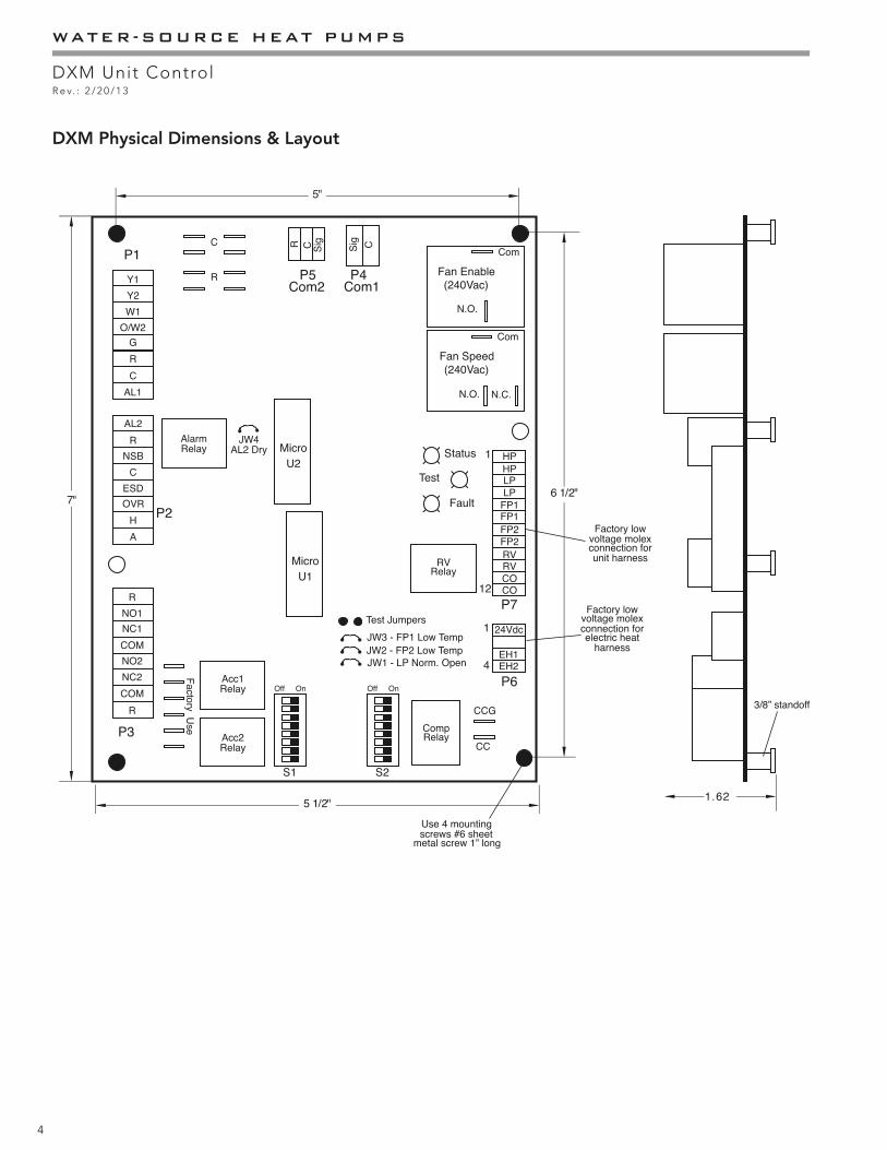
DXM Physical Dimensions & Layout

5
THE SMART SOLUTION FOR ENERGY EFFICIENCY
DXM Unit ControlR e v. : 2 / 2 0 / 1 3
Field Selectable InputsTest Mode - Test Mode allows the service personnel to check the operation of the control in a timely manner. By momentarily shorting the test terminals, the DXM Control enters a 20 minute Test Mode period in which all time delays are sped up 15 times. During Test Mode, the test LED will turn on. For diagnostic ease at the thermostat, the Alarm Relay will also cycle during Test Mode. The Alarm Relay will cycle on and off similar to the fault LED to indicate a code representing the last fault, at the thermostat. Note: Code 1 indicates there is no fault in memory; stated differently, the control has not faulted since the last power-down to power-up sequence.
Test Mode can be exited by shorting the test terminals for 3 seconds. Test Mode can also be entered and exited by cycling the G input, 3 times within a 60 second time period.
During Test Mode, the control monitors to see if the FP1 and FP2 thermistors are in the appropriate place. If the control is in Test Mode, the control will lockout, with Code 9, after 30 seconds if:a) the compressor is On in Cooling Mode and the FP1
sensor is colder than the FP2 sensor. or,b) the compressor is On in Heating Mode and the FP2
sensor is colder than the FP1 sensor.
Retry Mode - If the control is attempting a retry of a fault, the status LED will slow fl ash (slow fl ash = one fl ash every 2 seconds) to indicate the control is in process of retrying.Note: In the following fi eld confi guration options, jumper wires should be clipped ONLY when power is removed from the DXM Control.
Note: Jumpers 2 & 3 must not be clipped prior to adding antifreeze to the water loop. Antifreeze protection to 15°F required. Clipping JW2 & JW3 without antifreeze may result in freeze damage and will void the unit warranty.
Water Coil Low Temperature Cut-Out Limit Setting - Jumper 3 (JW3-FP1 Low Temp) provides fi eld selection of temperature limit setting for FP1 to be 30°F or 10°F. Not Clipped = 30°F. Clipped = 10°F.
Air Coil Low Temperature Cut-Out Limit Setting - Jumper 2 (JW2-FP2 Low Temp) provides fi eld selection of temperature limit setting for FP2 to be 30°F or 10°F.Not Clipped = 30°F. Clipped = 10°F.
Alarm Relay Setting - Jumper 4 (JW4-AL2 Dry) provides fi eld selection of Alarm Relay terminal AL2 to be jumpered to 24VAC or to be dry (no connection).Not Clipped = AL2 connected to R. Clipped = AL2 dry contacts (no connection).
Low Pressure Normally Open - Jumper 1 (JW1-LP Norm Open) Provides fi eld selection for low pressure input to be normally closed or normally open.Not Clipped = LP normally closed. Clipped = LP normally open.
DIP Switches
Note: In the following fi eld confi guration options, DIP switches should only be moved when power is removed from the DXM Control to ensure proper operation.
DIP Package #1 (S1)DIP Package #1 is 8 position and provides the following setup selections.
DIP 1.1: Unit Performance Sentinel Disable - Provides fi eld selection to disable the UPS feature. On = Enabled. Off = Disabled.
DIP 1.2: Compressor Relay Staging Operation - Provides selection of Compressor Relay staging operation. The Compressor Relay can be selected to turn on with Stage 1 or Stage 2 call from the thermostat. This is used with Dual Stage units (2 compressors where 2 DXM Controls are being used) or with master/slave applications. In master/slave applications, each compressor and fan will stage according to its appropriate DIP 1.2. If set to stage 2, the compressor will have a 3 second on-delay before energizing during a Stage 2 demand. Also, if set for stage 2, the Alarm Relay will NOT cycle during Test Mode.On = Stage 1. Off = Stage 2.
DIP 1.3: Thermostat Type (Heat/Cool) - Provides selection of thermostat type. Heat Pump or Heat/Cool thermostats can be selected. When in Heat/Cool Mode, Y1 is input call for Cooling Stage 1, Y2 is input call for Cooling Stage 2, W1 is input call for Heating Stage 1, and O/W2 is input call for Heating Stage 2. In Heat Pump Mode, Y1 is input call for Compressor Stage 1, Y2 is input call for Compressor Stage 2, W1 is input call for Heating Stage 3 or Emergency Heat, and O/W2 is the input call for RV (heating or cooling dependent upon DIP 1.4).On = Heat Pump. Off = Heat/Cool.
DXM Controls

6
WATER-SOURCE HEAT PUMPS
DXM Unit ControlR e v. : 2 / 2 0 / 1 3
DIP 1.4: Thermostat Type (O/B) - Provides selection of thermostat type. Heat pump thermostats with “O” output on with Cooling or “B” output on with Heating can be selected.On = HP Stat with O output with cooling. Off = HP Stat with B output with heating.
DIP 1.5: Dehumidifi cation Mode - Provides selection of normal or Dehumidifi cation Fan Mode. In Dehumidifi cation Mode, the fan speed relay will remain off during Cooling Stage 2. In Normal Mode, the fan speed relay will turn on during Cooling Stage 2.On = Normal Fan Mode. Off = Dehumidifi cation Mode.
DIP 1.6: DDC Output at EH2 - DIP Switch 1.6 provides selection for DDC operation. If set to DDC Output at EH2, the EH2 terminal will continuously output the last fault code of the controller. If set to EH2 normal, then the EH2 will operate as standard electric heat output.On = EH2 Normal. Off = DDC Output at EH2.
DIP 1.7: Boilerless Operation - Provides selection of Boilerless Operation. In Boilerless Mode, only the compressor is used for Heating Mode when FP1 is above the temperature specifi ed by the setting of DIP 1.8. If DIP 1.8 is set for 50°F, then the compressor is used for heating as long as FP1 is above 50°F. Below 50°F, the compressor is not used and the control goes into Emergency Heat Mode, staging on EH1 and EH2 to provide heating.
If a thermal switch is being used in place of the FP1 thermistor, then only the compressor will be used for Heating Mode when the FP1 terminals are closed. If the FP1 terminals are open, then the compressor is not used and the control goes into Emergency Heat Mode.
Table 2: Accessory Relay 2 Confi guration
Table 1: Accessory Relay 1 Confi gurationDIP 2.1 DIP 2.2 DIP 2.3 ACC1 Relay Option
ON ON ON Cycle with fanOFF ON ON Digital NSBON OFF ON Water Valve - Slow openingON ON OFF OADOFF OFF OFF Reheat Option - HumidistatOFF ON OFF Reheat Option - Dehumidistat
All other DIP combinations are invalid
DIP 2.4 DIP 2.5 DIP 2.6 ACC2 Relay OptionON ON ON Cycle with compressorOFF ON ON Digital NSBON OFF ON Water Valve - Slow OpeningON ON OFF OAD
All other DIP combinations are invalid
On = normal. Off = Boilerless operation.DIP 1.8: Boilerless Changeover Temperature - Provides selection of boilerless changeover temperature setpoint. On = 50°F. Off = 40°F.
DIP Package #2 (S2)DIP Package #2 is 8 position and provides the following setup selections.
DIP 2.1: Accessory1 relay personality - Provides selection of Acc1 relay personality. See Table 2.DIP 2.2: Accessory1 relay personality - Provides selection of Acc1 relay personality. See Table 2.DIP 2.3: Accessory1 relay personality - Provides selection of Acc1 relay option. See Table 2.DIP 2.4: Accessory2 relay personality - Provides selection of Acc2 relay personality. See Table 3.DIP 2.5: Accessory2 relay personality - Provides selection of Acc2 relay personality. See Table 3.DIP 2.6: Accessory2 relay personality - Provides selection of Acc2 relay option. See Table 3.DIP 2.7: Auto Dehumidifi cation Fan Mode or High Fan Mode - Provides selection of Auto Dehumidifi cation Fan Mode or High Fan Mode. In Auto Dehumidifi cation Mode, the Fan Speed relay will remain off during Cooling Stage 2 IF the H input is active. In High Fan Mode, the Fan Enable and Fan Speed relays will turn on when the H input is active.
On = Auto Dehumidifi cation Mode. Off = High Fan Mode.
DIP Switch 2.8: Factory Setting - Normal position is On. Do not change selection unless instructed to do so by the Factory.
Safety FeaturesThe following safety features are provided to protect the compressor, heat exchangers, wiring and other components from damage caused by operation outside of design conditions.
Anti-Short Cycle Protection - The control features a 5 minute anti-short cycle protection for the compressor. Note: The 5 minute anti-short cycle also occurs at power up.
Random Start - The control features a 5-80 second random start upon power up. The random start delay will be present after a control power up and after returning from Night Setback or Emergency Shutdown modes.Extended Compressor Operation Monitoring - If the compressor relay has been on for 4 continuous hours, then the control will automatically turn off the compressor

7
THE SMART SOLUTION FOR ENERGY EFFICIENCY
DXM Unit ControlR e v. : 2 / 2 0 / 1 3
relay and wait the short cycle protection time. All appropriate safeties including the LP will be monitored during the off time. If all operation is normal, and if the compressor demand is still present, the control will turn the compressor back on.
Fault Retry - In Fault Retry Mode, the Status LED begins slow fl ashing to signal that the control is trying to recover from a fault input. The Fault LED will also begin fl ashing a code representing the last fault, which occurred. The DXM Control will stage off the outputs and then “try again” to satisfy the thermostat call for compressor. Once the thermostat input calls are satisfi ed, the control will continue on as if no fault occurred. If 3 consecutive faults occur without satisfying the thermostat call for compressor, then the control will go to Lockout Mode. The last fault causing the lockout will be stored in memory and is displayed by the Fault LED.Note: If “1 Try” is selected for FP1 and FP2, then there will be no “retries” for FP1 and FP2 faults. The control will only try one time for these faults.
Lockout - In Lockout Mode, the Status LED will begin fast fl ashing. The Fault LED will be fl ashing a code representing the last fault, which occurred that caused the lockout. The compressor relay is turned off immediately. Lockout Mode can be soft reset via the thermostat by removing the call for compressor, or can be hard reset via the disconnect. The last fault causing the lockout will be stored in memory and is displayed by the Fault LED.
Lockout with Emergency Heat - If the DXM is confi gured for Heat Pump thermostat Mode (see DIP 1.3), the DXM is in Lockout Mode, and the W input becomes active, then Emergency Heat Mode will occur during Lockout.
High Pressure Switch - When the High Pressure Switch opens due to high refrigerant pressures, the Compressor relay is de-energized immediately since the High Pressure Switch is in series with the compressor contactor coil. The High Pressure Fault recognition is immediate as well. The Fault LED will immediately begin fl ashing Code 2 when a High Pressure Fault occurs.
High Pressure Lockout Code = 2
CAUTION! CAUTION! Do not restart units without inspection and remedy of faulting condition. Equipment damage may occur.
Example: 2 quick fl ashes, 10-sec pause, 2 quick fl ashes, 10-sec. pause, etc.
Low Pressure Switch - The Low Pressure Switch must be open and remain open for 30 continuous seconds during a compressor “on” cycle to be recognized as a Low Pressure fault. If the low pressure switch is open for 30 seconds prior to compressor power up it will be considered a low pressure (loss of charge) fault. The Low Pressure Switch input is bypassed for the initial 120 seconds of a compressor run cycle. The Fault LED will immediately begin fl ashing Code 3 when a Low Pressure Fault occurs.
Low Pressure Lockout Code = 3
Water Coil Low Temperature Cut-Out Limit (FP1) - The control will recognize an FP1 fault, during a compressor run cycle if:a) the thermistor temperature is below the selected low
temperature protection limit setting, ANDb) the thermistor temperature is rising (getting warmer)
at a rate LESS than 2°F per 30 second time period.
The FP1 input is bypassed for the initial 120 seconds of a compressor run cycle. The Fault LED will immediately begin fl ashing Code 4 when a FP1 Fault occurs.
FP1 Lockout Code = 4
Air Coil Low Temperature Cut-Out Limit (FP2) - The control will recognize an FP2 fault, during a compressor run cycle if:a) the thermistor temperature is below the selected low
temperature protection limit setting, ANDb) the thermistor temperature is rising (getting warmer)
at a rate LESS than 2°F per 30 second time period.
The FP2 input is bypassed for the initial 120 seconds of a compressor run cycle. The Fault LED will immediately begin fl ashing Code 5 when a FP2 Fault occurs.
FP2 Lockout Code = 5
Condensate Overfl ow - The Condensate Overfl ow sensor must sense overfl ow levels for 30 continuous seconds to be recognized as a CO fault. Condensate Overfl ow will be monitored at all times. The Fault LED will immediately begin fl ashing Code 6 when a Condensate Overfl ow Fault occurs. Condensate overfl ow will be monitored during compressor run cycle.
CO Lockout Code = 6

8
WATER-SOURCE HEAT PUMPS
DXM Unit ControlR e v. : 2 / 2 0 / 1 3
Over/Under Voltage Shutdown - An Over/Under Voltage condition exists when the control voltage is outside the range of 18VAC to 31.5VAC. Over/Under Voltage Shutdown is self-resetting in that if the voltage comes back within range of 18.5VAC to 31VAC for at least 0.5 seconds, then normal operation is restored. This is not considered a fault or lockout. If the DXM is in over/under voltage shutdown for 15 minutes, the Alarm Relay will close.Over/Under Voltage Shutdown Code = 7
Unit Performance Sentinel-UPS (patent pending) - The UPS feature warns when the heat pump is operating ineffi ciently. A UPS condition exists when:a) In Heating Mode with compressor energized, if FP2 is
greater than 125°F for 30 continuous seconds, orb) In Cooling Mode with compressor energized, if FP1
is greater than 125°F for 30 continuous seconds, OR FP2 is less than 40°F for 30 continuous seconds.
If a UPS condition occurs, the control will immediately go to UPS warning. The status LED will remain on as if the control is in Normal Mode. (see "LED and Alarm Relay Operation Table"). Outputs of the control, excluding Fault LED and Alarm Relay, will NOT be affected by UPS. The UPS condition cannot occur during a compressor off cycle. During UPS warning, the Alarm Relay will cycle on and off. The cycle rate will be On for 5 seconds, Off for 25 seconds, On for 5 seconds, Off for 25 seconds, etc.
Unit Performance Sentinel Warning Code = 8
Swapped FP1/FP2 Thermistors - During Test Mode, the control monitors to see if the FP1 and FP2 thermistors are in the appropriate place. If the control is in Test Mode, the control will lockout, with Code 9, after 30 seconds if:a) the compressor is On in Cooling Mode and the FP1
sensor is colder than the FP2 sensor. Or,b) the compressor is On in Heating Mode and the FP2
sensor is colder than the FP1 sensor.
Swapped FP1/FP2 Thermistor Code = 9.
ESD - The ESD (Emergency Shut Down) Mode is utilized when the ERV (Energy Recovery Ventilator) option is applied to an TRE series rooftop unit to indicate an ERV fault. A contact closure at the ERV unit will connect common to the ESD terminal, which will shut down the rooftop/ERV units. The green status light will fl ash code 3 when the unit is in ESD Mode. The ESD Mode can also be enabled from an external common signal to terminal ESD (see “Thermostat Inputs” section for details).
ESD Mode = code 3 (green “status” LED)
Diagnostic Features - The Status LED and Fault LED on the DXM Control advises service personnel of the current status of the DXM Control. The Status LED will indicate the current mode that the DXM Control is in. The Fault LED will ALWAYS fl ash a code representing the LAST fault in memory. If there is no fault on memory, then the Fault LED will fl ash Code 1. See Table 4 for a complete listing of codes.
Table 3: LED and Alarm Relay Output Table
Notes:a) "Flashing Appropriate Code" means that the Fault LED will
ALWAYS fl ash a code representing the LAST fault in memory. If there is no fault in memory, the Fault LED will fl ash code 1.
b) Codes will be displayed with a 10 second Fault LED off period.
c) Slow fl ash will be 1 fl ash per every 2 seconds.d) Fast fl ash will be 2 fl ash per every 1 second.e) On pulse 1/3 sec.; off pulse 1/3 sec.
Description of Operation
Status LED(Green)
Test LED (Yellow)
Fault LED (Red) Alarm Relay
Normal Mode ON - OFF Open
Normal Mode with UPS ON - Flashing Code 8 Cycle (Closed 5 seconds, open 25 seconds)
DXM is Non-functional OFF OFF OFF OpenFault Retry Slow Flash - Flashing Fault Code Open
Lockout Fast Flash - Flashing Fault Code ClosedTest Mode - ON - -
Night Setback Flashing Code 2 - - -ESD Flashing Code 3 - - -
Invalid T-Stat Inputs Flashing Code 4 - - -HP Fault Slow Flash - Flashing Code 2 OpenLP Fault Slow Flash - Flashing Code 3 Open
FP1 Fault Slow Flash - Flashing Code 4 OpenFP2 Fault Slow Flash - Flashing Code 5 OpenCO Fault Slow Flash - Flashing Code 6 Open
Over/Under Voltage Slow Flash - Flashing Code 7 Open (Closed after 15 minutes)

9
THE SMART SOLUTION FOR ENERGY EFFICIENCY
DXM Unit ControlR e v. : 2 / 2 0 / 1 3
UNIT OPERATION DESCRIPTION
Power Up - The unit will not operate until all the inputs and safety controls are checked for normal conditions. Note: The compressor will have a 5-minute anti-short cycle delay at power-up.
Standby/Fan Only - In Standby Mode, the compressor will be off. The Fan Enable, Fan Speed, and RV relays may be on if appropriate inputs are present. If there is a Fan 1 demand, then the Fan Enable relay will turn on immediately. If there is a Fan 2 demand, then the Fan Enable and Fan Speed relays will turn on immediately.
Note: DIP1.5 (Dehum Fan Mode Select) has no effect upon Fan 1 and Fan 2 outputs.
The RV relay will not directly track the input demands for RV, the DXM Control will employ “smart RV” control. This ensures that the RV will only switch positions if the thermostat has called for a Heating/Cooling Mode change.
Heating Stage 1 - In Heating Stage 1 Mode, the Fan Enable and Compressor relays are turned on immediately. If confi gured as Stage 2 (DIP1.2 = off), then the compressor and fan will not turn on until there is Stage 2 demand. The Fan Enable relay and Compressor relay are turned off immediately when the Heating Stage 1 demand is removed. The control reverts to Standby Mode. If there is a Master/Slave situation or a Dual Compressor situation, all Compressor relays and related functions will track with their associated DIP1.2.
Heating Stage 2 - In Heating Stage 2 Mode, the Fan Enable and Compressor relays remain on. The Fan Speed relay is turned on immediately. The Fan Speed relay is turned off immediately when the Heating Stage 2 demand is removed. The control reverts to Heating Stage 1 Mode. If there is a Master/Slave situation or a Dual Compressor situation, all Compressor relays and related functions will track with their associated DIP1.2.
Heating Stage 3 - In Heating Stage 3 Mode, the Fan Enable, Fan Speed and Compressor relays will remain on. EH1 output is turned on immediately. With continuing Heating Stage 3 demand, EH2 will turn on after 10 minutes. EH1 and EH2 are turned off immediately when the Heating Stage 3 demand is removed. The control reverts to Heating Stage 2 Mode. During Heating Stage 3 Mode, EH2 will be off (or will turn off if already on) if FP1 is greater than 45°F AND FP2 is greater than 110°F (FP2 greater than 110°F includes the condition that FP2 is shorted). This condition will have a 30-second recognition time. During Heating Stage 3 Mode, EH1, EH2, Fan Enable and Fan Speed will be on if the G input is not active.
Emergency Heat - In Emergency Heat Mode, the Fan Enable and Fan Speed relays are turned on. EH1 is turned on immediately. With continuing Emergency Heat demand, EH2 will turn on after 5 minutes. EH1 and EH2 are turned off immediately when the Emergency Heat demand is removed. The Fan Enable and Fan Speed relays will turn off after a 60-second delay. The control reverts to Standby Mode. During Emergency Heat Mode, EH1, EH2, Fan Enable and Fan Speed will be on if the G input is not active.
Cooling Stage 1 - In Cooling Stage 1 Mode, the Fan Enable, Compressor, and RV relays are turned on immediately. If confi gured as Stage 2 (DIP1.2 = off), then the compressor and fan will not turn on until there is Stage 2 demand. The Fan Enable and Compressor relays are turned off immediately when the Cooling Stage 1 demand is removed. The control reverts to Standby Mode. The RV relay remains on until there is a Heating demand. If there is a Master/Slave situation or a Dual Compressor situation, all Compressor relays and related functions will track with their associated DIP1.2.
Cooling Stage 2 - In Cooling Stage 2 Mode, the Fan Enable, Compressor, and RV relays remain on. The Fan Speed relay is turned on immediately (see DIP1.5). The Fan Speed relay is turned off immediately when the Cooling Stage 2 demand is removed. The control reverts to Cooling Stage 1 Mode. If there is a Master/Slave situation or a dual compressor situation, all compressor relays and related functions will track with their associated DIP1.2.
Night Low Limit (NLL) Staged Heating - In NLL Staged Heating Mode, the OVR input becomes active and is recognized as a call for Heating (OVR is an alternate means of calling for Heating Mode). In NLL Staged Heating Mode, the control will immediately go into Heating Stage 1 Mode with an additional 30 minutes of NLL demand, the control will go into Heating Stage 2 Mode. With an additional 30 minutes of NLL demand, the control will go into Heating Stage 3 Mode.
Special DXM Application Notes - Generally the following applications are based upon confi guring the accessory relays. Cycle with Fan - If Accessory relay 1 is confi gured to “cycle with fan”, Accessory relay 1 will be on any time the Fan Enable relay is on.
Cycle with Compressor - If Accessory relay 2 is confi gured to “cycle with compressor”, Accessory relay 2 will be on any time the Compressor relay is on.

10
WATER-SOURCE HEAT PUMPS
DXM Unit ControlR e v. : 2 / 2 0 / 1 3
Digital Night Setback - If an Accessory relay is confi gured for Digital NSB, the Accessory relay will be on any time the NSB input is connected to Ground “C”. Note: If there are no Accessory relays confi gured for Digital NSB, then the NSB and OVR inputs are automatically confi gured for “mechanical” operation. See Mechanical NSB operation below.
Note: Digital Night Setback feature requires a compatible thermostat. Contact manufacturer for information on compatible thermostats.
Mechanical Night Setback - When the NSB input is connected to Ground “C”, all thermostat inputs (G, Y1, Y2, W1, and O/W2) are ignored. A thermostat setback Heating call can then be connected to the OVR input. If the OVR input becomes active, then the DXM will enter NLL Staged Heating Mode. NLL Staged Heating Mode would then provide heating during the NSB period.
Water Valve/Slow Opening - If an Accessory relay is confi gured for Water Valve/Slow Opening, the Accessory relay will turn on 60 seconds prior to the Compressor Relay turning on.
Outside Air Damper - If an Accessory relay is confi gured for OAD, the Accessory relay will normally turn on any time the Fan Enable relay is on. But, following a return from NSB (NSB input no lrelonger connected to Ground “C”) to Normal Mode, the Accessory Relay will not turn on for 30 minutes even if the Fan Enable Relay is on. After this 30-minute timer expires, the Accessory Relay will turn on if the Fan Enable Relay is on.
Dehumidifi cation Operation with DXM - A heat pump equipped with a dedicated Dehumidifi cation Mode can operate in three modes, cooling, cooling with reheat, and heating. The cooling/heating modes are like any of our other WSHP. The reversing valve (“O” signal) is energized in cooling, along with the compressor contactor(s) and blower relay. In the Heating Mode the reversing valve is de-energized. Almost any thermostat will activate the heat pump in heating or cooling modes. The Reheat Mode requires a either a separate humidistat/dehumidistat or a thermostat that has an integrated dehumidifi cation function for activation. The DXM board is confi gured to work with either a humidistat or dehumidistat input to terminal “H” (DIP switch settings for the DXM board are shown in table 2). Upon receiving an “H” input, the DXM board will activate the Cooling Mode and engage reheat. Table 5 shows the relationship between thermostat input signals and unit operation.
Thermostat Inputs - Table 5 shows the resulting demand from differing combinations of inputs.
Y1 - Y1 is the input for compressor stage 1 if DIP1.3 = on. Y1 is the input for Cooling Stage 1 if DIP1.3 = off.Y2 - Y2 is the input for compressor stage 2 if DIP1.3 = on. Y2 is the input for Cooling Stage 2 if DIP1.3 = off.W1 - If Y1 and Y2 are active and DIP1.3 = on, then W1 is the input for Heating Stage 3. If Y1 and Y2 are not active and DIP1.3 = on, then W1 is the input for Emergency Heat. If DIP1.3 = off, then W1 is the input for Heating Stage 1.
O/W2 - O/W2 is the input for Reversing Valve Relay if DIP1.3 = on and DIP1.4 = on. O/W2 is the input for Heating Stage 2 if DIP1.3 = off. O/W2 is the input for
Table 4: Thermostat Inputs with Resulting Demands
1 Cooling input takes priority over dehumidify input.2 DXM is programmed to ignore the H demand when the unit is in heating mode.3 Above inputs assume DIP 1.3 is in the heat pump position, and DIP 1.4 is in the O position. When 1.3 is in the heat/cool position, Y1 & Y2 are used for cooling inputs; W1 and O/W2 are used for heating inputs. When 1.4 is in the B position, the O/W2 column would be opposite logic.
4 N/A for single stage units; Full load operation for dual capacity units.5 ON/OFF = Either ON or OFF; H/C = Either Heating or Cooling.
Thermostat Operating Modes
ModeInput3 Output
O/W2 G Y1 Y24 W1 H RV Fan 1st stg H/C 2nd stg H/C4 AUX Reheat
No Demand ON/OFF OFF OFF OFF OFF OFF ON/OFF OFF OFF OFF OFF OFF
Fan Only ON/OFF ON OFF OFF OFF OFF ON/OFF ON OFF OFF OFF OFF
Cooling 1st Stage ON ON ON OFF OFF OFF ON ON ON OFF OFF OFF
Cooling 2nd Stage ON ON ON ON OFF OFF ON ON ON ON OFF OFF
Cooling & Dehumidistat1 ON ON ON ON/OFF OFF ON ON ON ON ON/OFF OFF OFF
Dehumidistat Only ON/OFF OFF OFF OFF OFF ON ON ON ON ON OFF ON
Heating 1st Stage OFF ON ON OFF OFF OFF OFF ON ON OFF OFF OFF
Heating 2nd Stage OFF ON ON ON OFF OFF OFF ON ON ON OFF OFF
Heating 3rd Stage OFF ON ON ON ON OFF OFF ON ON ON ON OFF
Heating & Dehumidistat2 OFF ON ON ON/OFF ON/OFF ON OFF ON ON ON/OFF ON/OFF OFF

11
THE SMART SOLUTION FOR ENERGY EFFICIENCY
DXM Unit ControlR e v. : 2 / 2 0 / 1 3
“Heat Mode” if DIP1.3 = on and DIP1.4 = off; this means that the thermostat outputs a “B” call when in Heating Mode and does NOT have an “O” output. The DXM Control will employ “Smart RV” control. This ensures that the RV will only switch positions if the thermostat has called for a Heating/Cooling Mode change.
G - G is the input for Fan Enable Relay.
NSB and Override - NSB is the input for Night Setback Mode. When Digital NSB is selected via the Accessory Relays DIPswitch inputs and the NSB input is connected to Ground “C”, then the appropriately confi gured Accessory Relay is turned on to signal the digital thermostat to go to Night Setback Setpoints. Stated differently, when confi gured for Digital NSB Mode, the Accessory Relay directly tracks the NSB input.
Note: Digital Night Setback feature requires a compatible thermostat. Contact manufacturer for information on compatible thermostats.
When Digital NSB is NOT selected via the Accessory Relays DIP switch inputs and the NSB input is connected to Ground “C”, then Y1, Y2, W1 and O/W2 and G are ignored. During this time period, if OVR is momentarily connected to 24VAC, then Y1, Y2, W1 and O/W2 and G are once again monitored for 2 hours. After the 2 hour override period, the DXM reverts back to ignoring Y1, Y2, W1, and O/W2 and G, assuming the NSB input is still connected to Ground “C”. There will be a random start timer when coming back from NSB Mode.
Note: The maximum number of DXM Controls with daisy-chained "NSB" terminals is 75. Also, the maximum total wire resistance of the "NSB" wiring is 500 Ohms.
ESD - ESD is the input for Emergency Shutdown Mode. When the ESD input is connected to Ground “C”, all inputs are ignored and all outputs are turned off. There will be a random start timer when coming back from ESD.
OVR - OVR is the input for Night Setback Override or Night Low Limit Staged Heating input (NLL). When Digital NSB is NOT selected via the Accessory Relays DIP switch inputs and NSB is connected to Ground “C”, then if OVR is momentarily connected to 24VAC (minimum 1 second) then the OVR input is recognized as a Night Setback Override signal and the DXM Control reverts from Night Setback and begins monitoring thermostat inputs for heating and cooling calls for a 2 hour override period. If NSB is connected to ground "C", then if OVR is continuously connected to 24VAC, then the OVR input is recognized as a call for NLL Staged Heating and the control enters NLL Staged Heating.
H - The H input function is determined by the setting of DIP2.7. If DIP2.7 = on then the H input is defi ned as Automatic Dehumidifi cation Mode and is used as an “automatic” counterpart to DIP1.5, meaning if H is connected to 24VAC then the Fan Speed Relay will not turn on during Cooling Stage 2. If H is not connected to 24VAC then the Fan Speed Relay will turn on during Cooling Stage 2.
If DIP2.7 = off then the H input is defi ned as High Speed Fan input and is used as an input to call for High Speed Fan. If the control is in normal operating modes such as Standby, Cooling or Heating AND the H input is connected to 24VAC, then the Fan Enable and Fan Speed Relays will be on at all times (this operation is very similar to the G/Fan Enable operation).
Note: Units with Modulating Reheat Option operate differently from the above descriptions. DIP 1.5 should be in the ON position, and 2.7 should be in the OFF position. DIP 2.1, 2.2, and 2.3 indicate whether the DXM will operate with or without dehumidifi cation. Table 2 shows the two available selections for dehumidifi cation, humidistat/dehumidistat operation. With either selection (OFF/OFF/OFF or OFF/ON/OFF), the DXM microprocessor will operate in Reheat Mode when an external input from a humidistat or dehumidistat is applied to terminal H.
Other Outputs - Table 12 displays input and output signals. Electric Heat - Outputs EH1 and EH2 turn on whenever the DXM Control is in the following modes: Heating Stage 3, Emergency Heat, and Boilerless Operation. Status LED - The Status LED is green. The Status LED indicates what mode the DXM Control is in. See Table 4: “LED and Alarm Relay Operation”.Test LED - The Test LED is yellow. The Test LED will be on any time the control is in Test Mode. See Table 4: “LED and Alarm Relay Operation”.
Fault LED - The Fault LED is red. The Fault LED ALWAYS fl ashes the corresponding code for the last fault that has occurred. If there is no fault in memory, then the fault LED will fl ash Code 1. If the Fault type is “Primary” (HP, LP, FP1, FP2, or CO) then the Fault type will always be retained in memory (Primary faults will overwrite Secondary faults). If the Fault type is “Secondary” (Over/Under Voltage, UPS or Swapped FP1/FP2) then the Fault type will only be retained if there are no “Primary” faults in memory. The Secondary Fault types will not “overwrite” the Primary fault memory. See Table 4: “LED and Alarm Relay Operation”.

12
WATER-SOURCE HEAT PUMPS
DXM Unit ControlR e v. : 2 / 2 0 / 1 3
CommunicationsThere are two communications ports (Com1 and Com2) which provide robust communications to external DXM Control boards via a simple noise resistant low speed protocol. Wiring to Com1 and Com2 does NOT require the use of shielded wiring for operation; standard thermostat wire can be used.
Com1 - Com1 is used to communicate thermostat and external calls to other DXM Master/Slave controls. In this confi guration, up to 3 heat pumps can be controlled by one thermostat.
Note: Each heat pump could potentially be a Dual Compressor unit thus there could be up to 6 DXM Controls being controlled by one thermostat.However, only 1 DXM Control in each heat pump will be daisy-chained on Com1.etc
The Master DXM Control is defi ned as the DXM Control, which is directly connected to the wall-mounted thermostat, time clock, fi re alarm, and humidistat. The Master DXM communicates to the Slave DXM typical signals such as: Y1, Y2, W1, O/W2, G, NSB, ESD, OVR, and H. The Slave DXM Controls should have no direct connections to any exterior devices such as thermostats, time clocks, fi re alarms, humidistats, etc.
Note: When using the Com1 port on DXM controllers to Master/Slave units with ECM blowers it is necessary to revise the units’ low voltage wiring. Contact manufacturer’s Applications Department for details.
Com2 - Com2 is used to communicate thermostat and external calls to a second DXM Control being used for Dual Compressor Function. A heat pump with two compressors will have a DXM Control for each compressor. The Master DXM Control will handle all I/O with external sources as well as monitor and control operations of the Secondary DXM Control. The Master DXM Control is defi ned as the DXM Control, which is directly connected to the wall-mounted thermostat, time-clock, fi re alarm, and humidistat. The Master DXM communicates to the Secondary DXM typical signals such as: Y1, Y2, W1, O/W2, G, NSB, ESD, OVR, and H. The Secondary DXM Control should have no connections to any exterior devices such as thermostats, time clocks, fi re alarms, humidistats, etc.
Since the Master and Secondary DXM Controls share CO sensor and water valve/pump restart operations, these 2 signals are shared via communications as well. If either the Master or Secondary DXM Control senses a CO fault, both DXM Controls will fault and/or lockout due to the
CO signal. Regarding water valve/pump restart control, if either the Master or Secondary DXM Control faults or goes into Lockout Mode, it will continue to provide water valve/pump restart operation for the other functioning DXM Control.
Table 5: System Inputs With The Resulting Demand.
Table 5 describes demand changes with differing system input (ESD, NSB, OVR) and DIP input settings. Resulting Demand #1 is derived from Table 4.
Table 6: "H" Input With Resulting Demand Modes.
Table 6 describes demand changes with "H" input and DIP 2.1-2.3, and 2.7 settings. Resulting Demand #2 is derived from Table 5.
Resulting Demand #1 (From Table 4)
System InputsNSB Type
Resulting Demand #2
(After ESD, NSB)ESD NSB OVR
- X - - - ESD
Invalid - - - - Invalid
All (Excluding Invalid) - - - - All (Excluding Invalid)
All (Excluding Invalid) - - M - All (Excluding Invalid)
C1, C2 - - X - Invalid
OFF, F, H1, H2, or H3 - - X - NLL Staged Heating
EH - - X - EH
All (Excluding Invalid) - X - Mechanical Standby/OFF
All (Excluding Invalid) - X M MechanicalAll for 2 hours and then revert to Standby/OFF
(Excluding Invalid)
C1, C2 - X X Mechanical Invalid
OFF, F, H1, H2, or H3 - X X Mechanical NLL Staged Heating
EH - X X Mechanical EH
All (Excluding Invalid) - X - Digital All (Excluding Invalid)
All (Excluding Invalid) - X M Digital All (Excluding Invalid)
C1, C2 - X X Digital Invalid
OFF, F, H1, H2. or H3 - X X Digital NLL Staged Heating
EH - X X Digital EH
“M” is momentary input“X” is continuous input
Resulting Demand #2 (From Table 5) H Auto Dehum / F2
DIP 2.7
Resulting Demand # 3 (After DIP 2.1-2.3, 2.7 Logic)
Standby/OFF X Auto Dehum Mode Standby/OFF with Auto Dehum enabled
Standby/OFF X High Fan Mode F2
F1 X Auto Dehum Mode F1 with Auto Dehum enabled
F1 X High Fan Mode F2
C1 X Auto Dehum Mode C1 with fan destage
C1 X High Fan Mode *Cooling with High Fan
C2 X Auto Dehum Mode C2 with fan destage
C2 X High Fan Mode *Cooling with High Fan
H1 X Auto Dehum Mode H1
H1 X High Fan Mode Heating with High Fan
H2 X - H2
H3 X - H3
EH X - EH
Invalid - - Invalid
* = signifi es that High Fan is locked on regardless of any Dehum demands

13
THE SMART SOLUTION FOR ENERGY EFFICIENCY
DXM Unit ControlR e v. : 2 / 2 0 / 1 3
Table 8: Replacement Thermistor FP1, FP2 Part Numbers
Table 7: 1% Sensor Calibration Points
Chart 2: Thermistor Nominal Resistance
DXM Sensors
Pressure Switches - All pressure switches are designed to be normally closed during normal operating conditions, and to open upon fault.
Condensate Sensor - The Condensate Sensor input will fault upon sensing impedance less than 100,000 Ohms for 30 continuous seconds. The recommended design uses a single wire terminated with a male 1/4" quick connect located in the drain pan at desired trip level. Upon a high condensate level the water will short between the air coil and the quick connect producing a resistance less than 100,000 Ohms. Since condensate is free of impurities, it has no conductivity. Only the impurities from the drain pan and coil dust or dirt create the conductance. A second ground wire with appropriate terminal to the drain pan can be used with the control to replace the air coil ground path. The Condensate Sensor can also essentially be any open contact that closes upon a fault condition.
Thermistor Temperature Sensors - The thermistor is available in the following confi gurations shown in Table 7. The thermistor is an NTC (negative temperature coeffi cient) type. The sensor has a 1% tolerance and follows the Table 7 and Chart 2 shown. Table 9 shows the nominal resistance at any given temperature and can be used for fi eld service reference. The sensor will use a minimum of 24 awg wire and be epoxy embedded in the beryllium copper clip.
DXM Service & Application Notes
ThermistorType Tube OD
Lead Length (in.)36 48 96 192
FP1 (Gray)3/8, 1/2 17B0005N06 N/A 17B0005N04 N/A
5/8, 7/8 N/A N/A 17B0004N01 N/A
FP2 (Violet)3/8, 1/2 N/A 17B0005N02 N/A 17B0005N05
5/8, 7/8 N/A N/A N/A 17B0004N02
Temp (°F)
Minimum Resistance
(Ohm)
Maximum Resistance
(Ohm)
Nominal Resistance
(Ohm)78.5 9523 9715 9619
77.5 9650 9843 9746
76.5 10035 10236 10135
75.5 10282 10489 10385
33.5 30975 31598 31285
32.5 31871 32512 32190
31.5 32653 33310 32980
30.5 33728 34406 34065
1.5 80624 82244 81430
0.5 83327 85002 84160
0.0 84564 86264 85410

14
WATER-SOURCE HEAT PUMPS
DXM Unit ControlR e v. : 2 / 2 0 / 1 3
Table 9: Nominal Resistance at Various Temperatures DXM Thermostat Details
Thermostat Compatibility - Most all heat pump and heat/cool thermostats can be used with the DXM Control.
Anticipation Leakage Current - Maximum leakage current for "Y" is 50mA and for "W" is 20mA. Triacs can be used if leakage current is less than above. Thermostats with anticipators can be used if anticipation current is less than that specifi ed above.
Thermostat Signals - • "Y1, Y2, W1, O/W2" and "G" have a 1 second
recognition time when being activated or being removed.• "R" and "C" are from the transformer.• "AL1" and "AL2" originate from the Alarm Relay.• "A" is paralleled with the compressor output for use
with well water solenoid valves.
Safety Listing - The DXM Control is listed under the UL standard for limit controls and is CE listed uner EN50081-1 and EN61000-3.
Temp (ºC) Temp (ºF) Resistance (kOhm) Temp (ºC) Temp (ºF) Resistance
(kOhm)-17.8 0.0 85.34 55 131.0 2.99-17.5 0.5 84.00 56 132.8 2.88-16.9 1.5 81.38 57 134.6 2.77-12 10.4 61.70 58 136.4 2.67-11 12.2 58.40 59 138.2 2.58-10 14.0 55.30 60 140.0 2.49-9 15.8 52.38 61 141.8 2.40-8 17.6 49.64 62 143.6 2.32-7 19.4 47.05 63 145.4 2.23-6 21.2 44.61 64 147.2 2.16-5 23.0 42.32 65 149.0 2.08-4 24.8 40.15 66 150.8 2.01-3 26.6 38.11 67 152.6 1.94-2 28.4 36.18 68 154.4 1.88-1 30.2 34.37 69 156.2 1.810 32.0 32.65 70 158.0 1.751 33.8 31.03 71 159.8 1.692 35.6 29.50 72 161.6 1.643 37.4 28.05 73 163.4 1.584 39.2 26.69 74 165.2 1.535 41.0 25.39 75 167.0 1.486 42.8 24.17 76 168.8 1.437 44.6 23.02 77 170.6 1.398 46.4 21.92 78 172.4 1.349 48.2 20.88 79 174.2 1.30
10 50.0 19.90 80 176.0 1.2611 51.8 18.97 81 177.8 1.2212 53.6 18.09 82 179.6 1.1813 55.4 17.26 83 181.4 1.1414 57.2 16.46 84 183.2 1.1015 59.0 15.71 85 185.0 1.0716 60.8 15.00 86 186.8 1.0417 62.6 14.32 87 188.6 1.0118 64.4 13.68 88 190.4 0.9719 66.2 13.07 89 192.2 0.9420 68.0 12.49 90 194.0 0.9221 69.8 11.94 91 195.8 0.8922 71.6 11.42 92 197.6 0.8623 73.4 10.92 93 199.4 0.8424 75.2 10.45 94 201.2 0.8125 77.0 10.00 95 203.0 0.7926 78.8 9.57 96 204.8 0.7627 80.6 9.16 97 206.6 0.7428 82.4 8.78 98 208.4 0.7229 84.2 8.41 99 210.2 0.7030 86.0 8.06 100 212.0 0.6831 87.8 7.72 101 213.8 0.6632 89.6 7.40 102 215.6 0.6433 91.4 7.10 103 217.4 0.6234 93.2 6.81 104 219.2 0.6035 95.0 6.53 105 221.0 0.5936 96.8 6.27 106 222.8 0.5737 98.6 6.01 107 224.6 0.5538 100.4 5.77 108 226.4 0.5439 102.2 5.54 109 228.2 0.5240 104.0 5.33 110 230.0 0.5141 105.8 5.12 111 231.8 0.5042 107.6 4.92 112 233.6 0.4843 109.4 4.72 113 235.4 0.4744 111.2 4.54 114 237.2 0.4645 113.0 4.37 115 239.0 0.4446 114.8 4.20 116 240.8 0.4347 116.6 4.04 117 242.6 0.4248 118.4 3.89 118 244.4 0.4149 120.2 3.74 119 246.2 0.4050 122.0 3.60 120 248.0 0.3951 123.8 3.47 121 249.8 0.3852 125.6 3.34 122 251.6 0.3753 127.4 3.22 123 253.4 0.3654 129.2 3.10

15
THE SMART SOLUTION FOR ENERGY EFFICIENCY
DXM Unit ControlR e v. : 2 / 2 0 / 1 3
General - DXM board troubleshooting in general is best summarized as simply verifying inputs and outputs. After this process has been verifi ed, confi dence in board operation is confi rmed and the trouble must be else where. Below are some general guidelines required for developing training materials and procedures when applying the DXM Control.
DXM Field Inputs - All inputs are 24VAC from the thermostat and can be verifi ed using a Volt meter between C and Y1, Y2, W, O/W2 and G. See Table 10.
Sensor Inputs - All sensor inputs are 'paired wires' connecting each component with the board. Therefore continuity on pressure switches can be checked at the board connector.
The thermistor resistance should be measured with the connector removed so that only the impedance of the thermistor is measured. If desired, this reading can be compared to the chart shown in the thermistor section of this manual based upon the actual temperature of the thermistor clip. An ice bath can be used to check calibration of a thermistor if needed.
DXM Outputs - The compressor relay is 24VAC and can be verified using a voltmeter. The Alarm Relay can either be 24VAC as shipped or dry contacts (measure continuity during fault) for use with DDC by clipping the J4 jumper. Electric heat outputs are 24VDC and require a voltmeter set for DC to verify operation. When troubleshooting, measure from 24VDC terminal to EH1 or EH2 terminals. See the I/O Reference table.
Test Mode - Test Mode can be entered for 20 minutes by shorting the test pins. For Diagnostic ease at the thermostat, the Alarm Relay will also cycle during test mode. The Alarm Relay will cycle on and off similar to the fault LED to indicate a code representing the last fault, at the thermostat. Test Mode can also be entered and exited by cycling the G input, 3 times within a 60 second time period.
Table 10: DXM Input/Output Reference Table
Troubleshooting Information

16
WATER-SOURCE HEAT PUMPS
DXM Unit ControlR e v. : 2 / 2 0 / 1 3
Use the following troubleshooting fl ow chart to fi nd appropriate troubleshooting strategies on the following pages for the DXM Control and most water source heat pump applications.
Troubleshooting Chart
See "Doesnot operate
in clg"
See "Onlycompruns"
Start
Did unitattempt to
start?
Did unitlockout atstart-up?
Unit shortcycles?
Only fanruns?
Onlycompressor
runs?
Did unit lockoutafter a period of
operation?
Does unitoperate incooling?
Unit is OK!"See Performance
Troubleshooting" forfurther help
Check main power (see power problems)
Check fault LED codeon control board
Yes
No
No
No
No
No
Yes
No
Yes
See HPFault
SeeLP/LOC
Fault
See FP1Fault
See FP2Fault
SeeCondensate
Fault
See Over/Under
Voltage
No faultshown
ReplaceCXM/ DXM
See "Unitshort
cycles"
See "Onlyfan runs"
No
Yes
Yes
Yes
Yes
DXM

17
THE SMART SOLUTION FOR ENERGY EFFICIENCY
DXM Unit ControlR e v. : 2 / 2 0 / 1 3
DXM Wiring Diagram

18
WATER-SOURCE HEAT PUMPS
DXM Unit ControlR e v. : 2 / 2 0 / 1 3
Functional Troubleshooting
CAUTION! CAUTION! Do not restart units without inspection and remedy of faulting condition. Equipment damage may occur.
Fault Htg Clg Possible Cause Solution
Main power problems X X Green Status LED Off
Check line voltage circuit breaker and disconnect.Check for line voltage between L1 and L2 on the contactor.Check for 24VAC between R and C on CXM/DXM'Check primary/secondary voltage on transformer.
HP Fault Code 2
High Pressure
X Reduced or no water fl ow in coolingCheck pump operation or valve operation/setting.Check water fl ow adjust to proper fl ow rate.
X Water Temperature out of range in cooling Bring water temp within design parameters.
X Reduced or no air fl ow in heating
Check for dirty air fi lter and clean or replace.Check fan motor operation and airfl ow restrictions.Dirty Air Coil- construction dust etc.Too high of external static. Check static vs blower table.
X Air temperature out of range in heating Bring return air temp within design parameters.X X Overcharged with refrigerant Check superheat/subcooling vs typical operating condition table.X X Bad HP Switch Check switch continuity and operation. Replace.
LP/LOC FaultCode 3
Low Pressure / Loss of Charge
X X Insuffi cient charge Check for refrigerant leaks
X Compressor pump down at start-up Check charge and start-up water fl ow.
LT1 FaultCode 4
Water coil low temperature limit
X Reduced or no water fl ow in heatingCheck pump operation or water valve operation/setting.Plugged strainer or fi lter. Clean or replace..Check water fl ow adjust to proper fl ow rate.
X Inadequate antifreeze level Check antifreeze density with hydrometer.
X Improper temperature limit setting (30°F vs 10°F [-1°C vs -2°C]) Clip JW3 jumper for antifreeze (10°F [-12°C]) use.
X Water Temperature out of range Bring water temp within design parameters.X X Bad thermistor Check temp and impedance correlation per chart
LT2 FaultCode 5
Air coil low temperature limit
X Reduced or no air fl ow in cooling Check for dirty air fi lter and clean or replace.Check fan motor operation and airfl ow restrictions.Too high of external static. Check static vs blower table.
X Air Temperature out of range Too much cold vent air? Bring entering air temp within design parameters.
X Improper temperature limit setting (30°F vs 10°F [-1°C vs -12°C]) Normal airside applications will require 30°F [-1°C] only.
X X Bad thermistor Check temp and impedance correlation per chart.
Condensate Fault Code 6
X X Blocked drain Check for blockage and clean drain.X X Improper trap Check trap dimensions and location ahead of vent.
X Poor drainageCheck for piping slope away from unit.Check slope of unit toward outlet.Poor venting. Check vent location.
X Moisture on sensor Check for moisture shorting to air coil.X X Plugged air fi lter Replace air fi lter.x X Restricted Return Air Flow Find and eliminate restriction. Increase return duct and/or grille size.
Over/Under Voltage Code 7
(Auto resetting)
X X Under Voltage
Check power supply and 24VAC voltage before and during operation.Check power supply wire size.Check compressor starting. Need hard start kit?Check 24VAC and unit transformer tap for correct power supply voltage.
X X Over VoltageCheck power supply voltage and 24VAC before and during operation.Check 24VAC and unit transformer tap for correct power supply voltage.
Unit Performance SentinelCode 8
X Heating mode FP2>125°F [52°C] Check for poor air fl ow or overcharged unit.
X Cooling Mode FP1>125°F [52°C] OR FP2< 40ºF [4ºC]) Check for poor water fl ow, or air fl ow.
Swapped ThermistorCode 9 X X LT1 and LT2 swapped Reverse position of thermistors
No Fault Code ShownX X No compressor operation See "Only Fan Operates".X X Compressor overload Check and replace if necessary.X X Control board Reset power and check operation.
Unit Short Cycles
X X Dirty air fi lter Check and clean air fi lter.X X Unit in "test mode" Reset power or wait 20 minutes for auto exit.X X Unit selection Unit may be oversized for space. Check sizing for actual load of space.X X Compressor overload Check and replace if necessary
Only Fan Runs
X X Thermostat position Ensure thermostat set for heating or cooling operation.X X Unit locked out Check for lockout codes. Reset power.X X Compressor Overload Check compressor overload. Replace if necessary.
X X Thermostat wiring Check thermostat wiring at heat pump. Jumper Y and R for compressor operation in test mode.
Only Compressor Runs
X X Thermostat wiring Check G wiring at heat pump. Jumper G and R for fan operation
X XFan motor relay
Jumper G and R for fan operation. Check for Line voltage across BR contacts.
X X Check fan power enable relay operation (if present).X X Fan motor Check for line voltage at motor. Check capacitor.
X X Thermostat wiring Check thermostat wiring at heat pump. Jumper Y and R for compressor operation in test mode
Unit Doesn’t Operatein Cooling
X Reversing valveSet for cooling demand and check 24VAC on RV coil and at CXM/DXM board.If RV is stuck, run high pressure up by reducing water fl ow and while operating engage and disengage RV coil voltage to push valve.
X Thermostat setup Check for ‘O’ RV setup not ‘B’.X Thermostat wiring Check O wiring at heat pump. Jumper O and R for RV coil ‘click’.
X Thermostat wiring
Put thermostat in cooling mode. Check 24 VAC on O (check between C and O); check for 24 VAC on W (check between W and C). There should be voltage on O, but not on W. If voltage is present on W, thermostat may be bad or wired incorrectly.

19
THE SMART SOLUTION FOR ENERGY EFFICIENCY
DXM Unit ControlR e v. : 2 / 2 0 / 1 3
Performance Troubleshooting
Performance Troubleshooting Htg Clg Possible Cause Solution
Insuffi cient capacity/ Not cooling or heating
X X Dirty fi lter Replace or clean.
X Reduced or no air fl ow in heating
Check for dirty air fi lter and clean or replace.
Check fan motor operation and airfl ow restrictions.
Too high of external static. Check static vs. blower table.
X Reduced or no air fl ow in cooling
Check for dirty air fi lter and clean or replace.
Check fan motor operation and airfl ow restrictions.
Too high of external static. Check static vs. blower table.
X X Leaky duct work Check supply and return air temperatures at the unit and at distant duct registers if signifi cantly different, duct leaks are present.
X X Low refrigerant charge Check superheat and subcooling per chart.
X X Restricted metering device Check superheat and subcooling per chart. Replace.
X Defective reversing valve Perform RV touch test.
X X Thermostat improperly located Check location and for air drafts behind stat.
X X Unit undersized Recheck loads & sizing. Check sensible clg. load and heat pump capacity.
X X Scaling in water heat exchanger Perform scaling check and clean if necessary.
X X Inlet water too hot or too cold Check load, loop sizing, loop backfi ll, ground moisture.
High Head Pressure
X Reduced or no air fl ow in heating
Check for dirty air fi lter and clean or replace.
Check fan motor operation and air fl ow restrictions.
Too high of external static. Check static vs. blower table.
X Reduced or no water fl ow in coolingCheck pump operation or valve operation/setting.
Check water fl ow. Adjust to proper fl ow rate.
X Inlet water too hot Check load, loop sizing, loop backfi ll, ground moisture.
X Air temperature out of range in heating Bring return air temperature within design parameters.
X Scaling in water heat exchanger Perform scaling check and clean if necessary.
X X Unit overcharged Check superheat and subcooling. Re-weigh in charge.
X X Non-condensables in system Vacuum system and re-weigh in charge.
X X Restricted metering device. Check superheat and subcooling per chart. Replace.
Low Suction Pressure
X Reduced water fl ow in heating.
Check pump operation or water valve operation/setting.
Plugged strainer or fi lter. Clean or replace.
Check water fl ow. Adjust to proper fl ow rate.
X Water temperature out of range. Bring water temperature within design parameters.
X Reduced air fl ow in cooling.
Check for dirty air fi lter and clean or replace.
Check fan motor operation and air fl ow restrictions.
Too high of external static. Check static vs. blower table.
X Air temperature out of range Too much cold vent air? Bring entering air temperature within design parameters.
X X Insuffi cient charge Check for refrigerant leaks.
Low Discharge Air Temperature in Heating
X Too high of air fl ow Check fan motor speed selection and air fl ow chart.
X Poor performance See ‘Insuffi cient Capacity’
High humidityX Too high of air fl ow Check fan motor speed selection and airfl ow chart.
X Unit oversized Recheck loads & sizing. Check sensible clg load and heat pump capacity.

20
WATER-SOURCE HEAT PUMPS
DXM Unit ControlR e v. : 2 / 2 0 / 1 3
Revision History
Date: Item: Action:
02/20/13Functional Troubleshooting TablePerformance Troubleshooting TableNominal Resistance at Various Temp. Table
Updated
04/03/12 Communications Section Added Note
01/03/11 Format - All Pages Updated
06/11/10 Format - All Pages Updated
06/11/10 DXM Physical Dimensions & Layout Illustration Updated
06/11/10 Table 7: Replacement Thermistor FP1, FP2 Part Numbers Part Numbers Updated
10/30/09 Functional Troubleshooting Table Updated
01/5/09 First Published
We work continually to improve our products. As a result, the design and specifi cations of each product at the time of order may be changed without notice and may not be as described herein. Please contact our Customer Service Department at 1-405-745-6000 for specifi c information on the current design and specifi cations. Statements and other information contained herein are not express warranties and do not form the basis of any bargain between the parties, but are merely our opinion or commendation of its products.
We are a proud supporter of the Geothermal Exchange Organization - GEO. For more information visit geoexchange.org
© LSB, Inc. 2008
*97B0003N13*97B0003N13