dvg ec roof fan new - systemair.com
TRANSCRIPT
Fans | Air Handling Units | Air Distribution Products | Fire Safety | Air Curtains and Heating Products | Tunnel Fans
Roof Fan DVG ECSmoke extraction and daily ventilation in one!
400°C/120min 120°C
2 Roof Fan DVG EC
0 1.11 2.22 3.33 4.44 5.56 6.67 7.780
100
200
300
400
500
600
700
800
900
1000
1100
1200
Q [m³/s]
Pst
at [P
a]
0 4000 8000 12000 16000 20000 24000 28000Q [m³/h]
DVG-H ECDVG-V EC
800
630
560
450
355
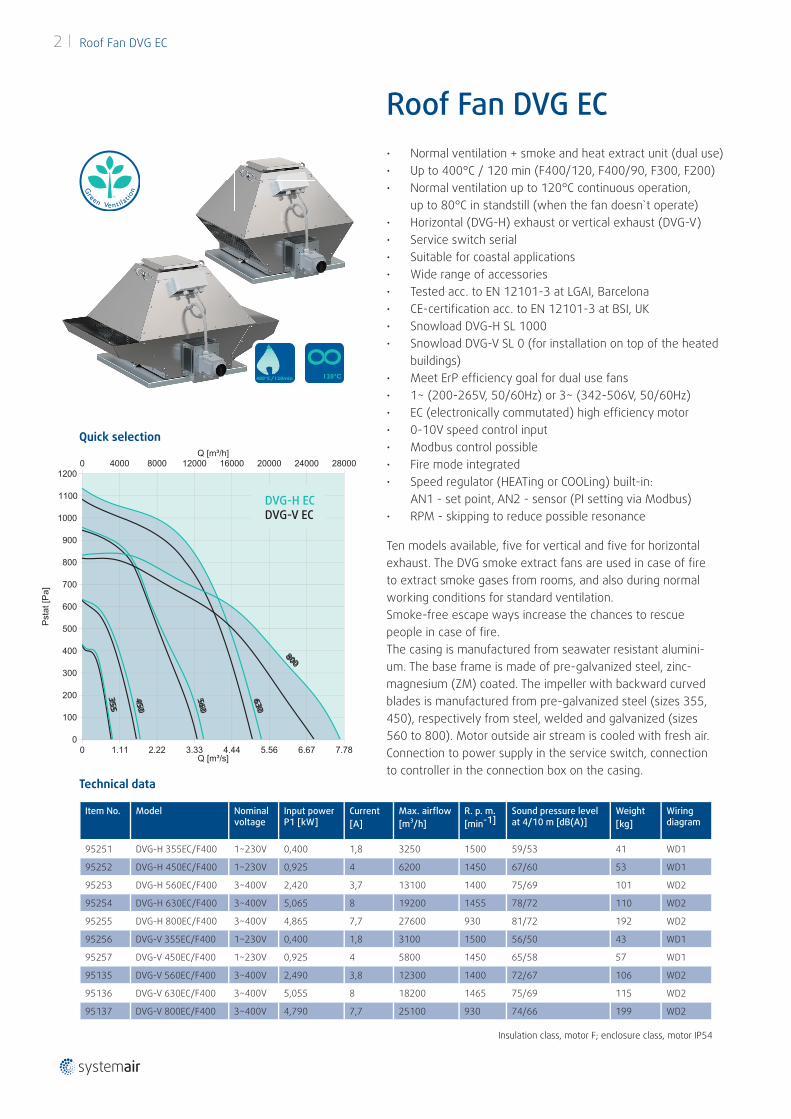
• Normal ventilation + smoke and heat extract unit (dual use)• Up to 400°C / 120 min (F400/120, F400/90, F300, F200)• Normal ventilation up to 120°C continuous operation,
up to 80°C in standstill (when the fan doesn`t operate)• Horizontal (DVG-H) exhaust or vertical exhaust (DVG-V)• Service switch serial• Suitable for coastal applications• Wide range of accessories• Tested acc. to EN 12101-3 at LGAI, Barcelona• CE-certifi cation acc. to EN 12101-3 at BSI, UK• Snowload DVG-H SL 1000• Snowload DVG-V SL 0 (for installation on top of the heated
buildings)• Meet ErP effi ciency goal for dual use fans• 1~ (200-265V, 50/60Hz) or 3~ (342-506V, 50/60Hz)• EC (electronically commutated) high effi ciency motor• 0-10V speed control input• Modbus control possible• Fire mode integrated• Speed regulator (HEATing or COOLing) built-in:
AN1 - set point, AN2 - sensor (PI setting via Modbus)• RPM - skipping to reduce possible resonance
Ten models available, fi ve for vertical and fi ve for horizontal exhaust. The DVG smoke extract fans are used in case of fi re to extract smoke gases from rooms, and also during normal working conditions for standard ventilation.Smoke-free escape ways increase the chances to rescue people in case of fi re. The casing is manufactured from seawater resistant alumini-um. The base frame is made of pre-galvanized steel, zinc-magnesium (ZM) coated. The impeller with backward curved blades is manufactured from pre-galvanized steel (sizes 355, 450), respectively from steel, welded and galvanized (sizes 560 to 800). Motor outside air stream is cooled with fresh air. Connection to power supply in the service switch, connection to controller in the connection box on the casing.
Item No. Model Nominal voltage
Input power P1 [kW]
Current[A]
Max. airfl ow[m³/h]
R. p. m.[min-1]
Sound pressure level at 4/10 m [dB(A)]
Weight[kg]
Wiring diagram
95251 DVG-H 355EC/F400 1~230V 0,400 1,8 3250 1500 59/53 41 WD1
95252 DVG-H 450EC/F400 1~230V 0,925 4 6200 1450 67/60 53 WD1
95253 DVG-H 560EC/F400 3~400V 2,420 3,7 13100 1400 75/69 101 WD2
95254 DVG-H 630EC/F400 3~400V 5,065 8 19200 1455 78/72 110 WD2
95255 DVG-H 800EC/F400 3~400V 4,865 7,7 27600 930 81/72 192 WD2
95256 DVG-V 355EC/F400 1~230V 0,400 1,8 3100 1500 56/50 43 WD1
95257 DVG-V 450EC/F400 1~230V 0,925 4 5800 1450 65/58 57 WD1
95135 DVG-V 560EC/F400 3~400V 2,490 3,8 12300 1400 72/67 106 WD2
95136 DVG-V 630EC/F400 3~400V 5,055 8 18200 1465 75/69 115 WD2
95137 DVG-V 800EC/F400 3~400V 4,790 7,7 25100 930 74/66 199 WD2
Technical data
400°C/120min 120°C
Roof Fan DVG EC
Quick selection
DVG-H ECDVG-V EC
800
630
560
450
355
Insulation class, motor F; enclosure class, motor IP54
Roof Fan DVG EC 3
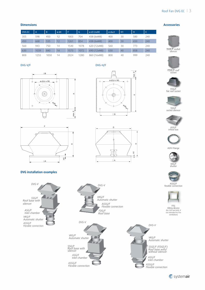
Dimensions
DVG-V/F DVG-H/F
DVG EC A B ø d4 F G ø d3 (nxM) ø duct H1 H E
355 598 450 12 1003 704 438 (6xM8) 400 30 580 240
450 668 535 12 1261 854 438 (6xM8) 400 30 650 240
560 943 750 14 1540 1078 620 (12xM8) 560 30 773 240
630 1039 840 14 1573 1072 690 (12xM8) 630 40 858 240
800 1255 1050 14 2024 1280 860 (16xM8) 800 40 999 240
Accessories
FDG/Ffl at roof socket
ASFV Flange
FDGE/F roof socket
SSGE/F socket silencer
SSG/Fsocket silencer
ASG/Finfl ow box
VKG/Fshutter
ASSG/Ffl exible connection
FTG tilting device
(for 355 and 450, if not intended for fi re
ventilation)
FDGE/F roof
SSGE/F socket
DVG installation examples
DVG-V
SSG/FSilencer
ASG/FInlet chamber
VKG/FAutomatic shutterASSG/FFlexible connection
DVG-V
SSG/FSilencer
ASG/FInlet chamber
VKG/FAutomatic shutter
ASSG/FFlexible connection
DVG-V
ASG/FInlet chamber
VKG/FAutomatic shutter
SSGE/F (FDGE/F)Silencer
ASSG/FFlexible connection
DVG-V
VKG/FAutomatic shutter
ASSG/FFlexible connection
FDG/FSilencerRoof base
DVG-V
SSG/FSilencer
ASG/FInlet chamber
VKG/FAutomatic shutterASSG/FFlexible connection
DVG-V
SSG/FSilencer
ASG/FInlet chamber
VKG/FAutomatic shutter
ASSG/FFlexible connection
DVG-V
ASG/FInlet chamber
VKG/FAutomatic shutter
SSGE/F (FDGE/F)Silencer
ASSG/FFlexible connection
DVG-V
VKG/FAutomatic shutter
ASSG/FFlexible connection
FDG/FSilencer
Roof base with/without silencer
DVG-V
SSG/FSilencer
ASG/FInlet chamber
VKG/FAutomatic shutterASSG/FFlexible connection
DVG-V
SSG/FSilencer
ASG/FInlet chamber
VKG/FAutomatic shutter
ASSG/FFlexible connection
DVG-V
ASG/FInlet chamber
VKG/FAutomatic shutter
SSGE/F (FDGE/F)Silencer
ASSG/FFlexible connection
DVG-V
VKG/FAutomatic shutter
ASSG/FFlexible connection
FDG/FSilencer
SSG/FRoof base with silencer
DVG-V
SSG/FSilencer
ASG/FInlet chamber
VKG/FAutomatic shutterASSG/FFlexible connection
DVG-V
SSG/FSilencer
ASG/FInlet chamber
VKG/FAutomatic shutter
ASSG/FFlexible connection
DVG-V
ASG/FInlet chamber
VKG/FAutomatic shutter
SSGE/F (FDGE/F)Silencer
ASSG/FFlexible connection
DVG-V
VKG/FAutomatic shutter
ASSG/FFlexible connection
FDG/FSilencer
Roof base with silencer
d3 d3
4 Roof Fan DVG EC
0 0.25 0.5 0.75 10
100
200
300
400
500
[m³/s][Pa]
0 1000 2000 3000[m³/h]
0 0.5 1 1.5 20
200
400
600
800
[m³/s]
[Pa]
0 2000 4000 6000[m³/h]
0 1 2 3 40
250
500
750
1000
[m³/s]
[Pa]
0 4000 8000 12000[m³/h]
0 2 4 60
300
600
900
1200
[m³/s]
[Pa]
0 5000 10000 15000 20000[m³/h]
0 2 4 6 80
250
500
750
1000
[m³/s]
[Pa]
0 5000 10000 15000 20000 25000[m³/h]
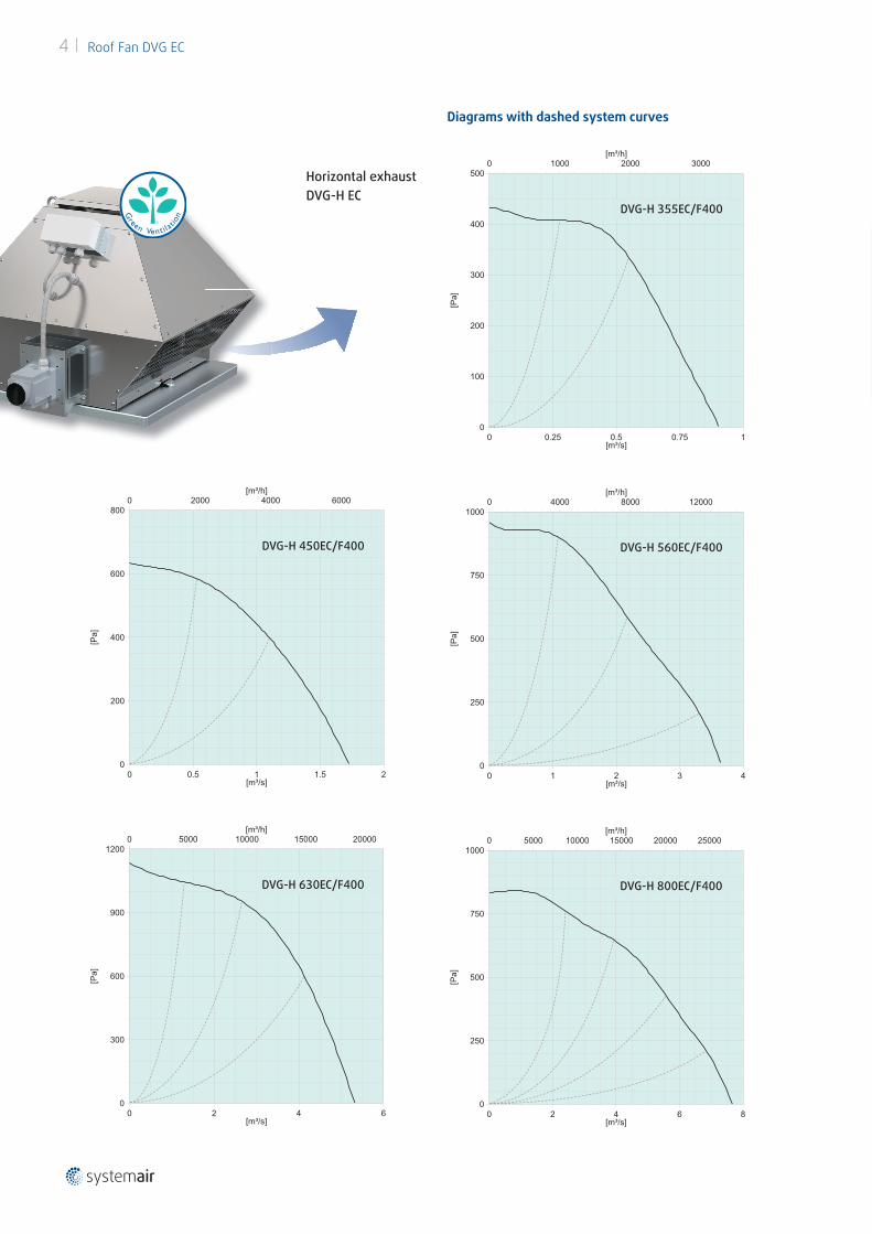
Diagrams with dashed system curves
DVG-H 355EC/F400
Horizontal exhaustDVG-H EC
DVG-H 560EC/F400
DVG-H 800EC/F400DVG-H 630EC/F400
DVG-H 450EC/F400
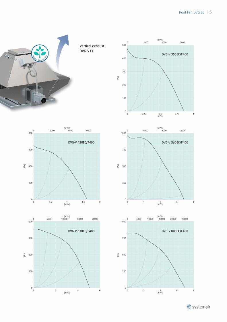
Roof Fan DVG EC 5
0 0.25 0.5 0.75 10
100
200
300
400
500
[m³/s][Pa]
0 1000 2000 3000[m³/h]
0 0.5 1 1.5 20
200
400
600
800
[m³/s]
[Pa]
0 2000 4000 6000[m³/h]
0 1 2 3 40
250
500
750
1000
[m³/s]
[Pa]
0 4000 8000 12000[m³/h]
0 2 4 60
300
600
900
1200
[m³/s]
[Pa]
0 5000 10000 15000 20000[m³/h]
0 2 4 6 80
250
500
750
1000
[m³/s]
[Pa]
0 5000 10000 15000 20000 25000[m³/h]
Vertical exhaustDVG-V EC
DVG-V 355EC/F400
DVG-V 450EC/F400
DVG-V 630EC/F400 DVG-V 800EC/F400
DVG-V 560EC/F400
6 Roof Fan DVG EC
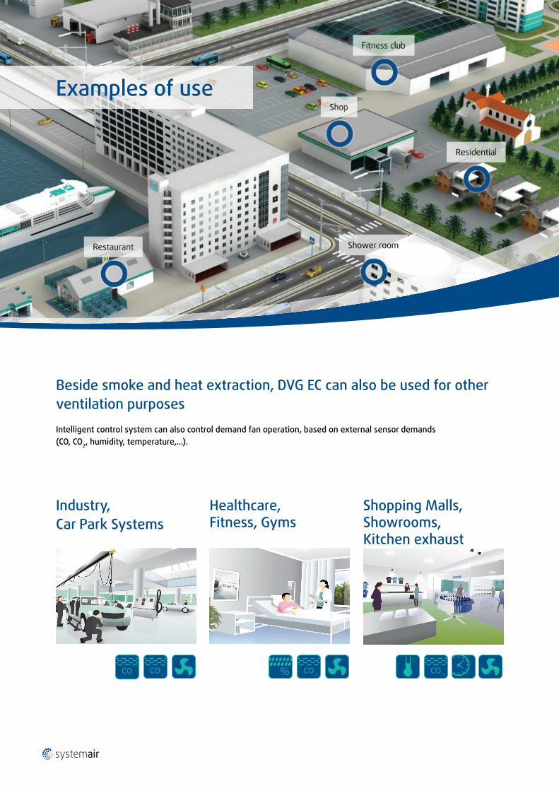
Beside smoke and heat extraction, DVG EC can also be used for other ventilation purposes
Intelligent control system can also control demand fan operation, based on external sensor demands (CO, CO2, humidity, temperature,...).
Industry, Car Park Systems
Shopping Malls, Showrooms, Kitchen exhaust
Healthcare,Fitness, Gyms
% CO 2
°C°C
% CO 2
°C°C
% CO 2
°C°C
% CO 2
°C°C
% CO 2
°C°C
% CO 2
°C°C
% CO 2
°C°C
% CO 2
°C°C
% CO 2
°C°C
Examples of use
CO
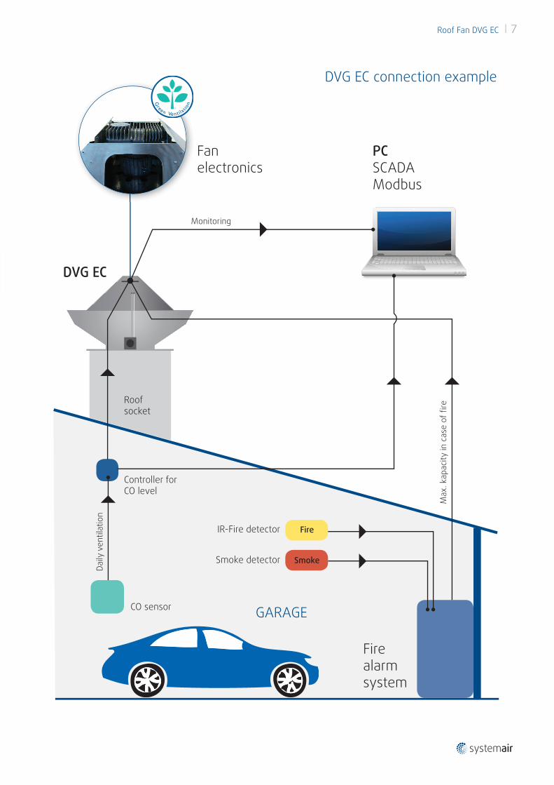
Roof Fan DVG EC 7
CO sensor
Controller for CO level
Smoke detector
IR-Fire detector Fire
Smoke
Daily
ven
tilat
ion
Monitoring
Max
. kap
acity
in c
ase
of fi
re
GARAGE
Fire alarm system
PCSCADAModbus
DVG EC
Roof socket
Fan electronics
DVG EC connection example
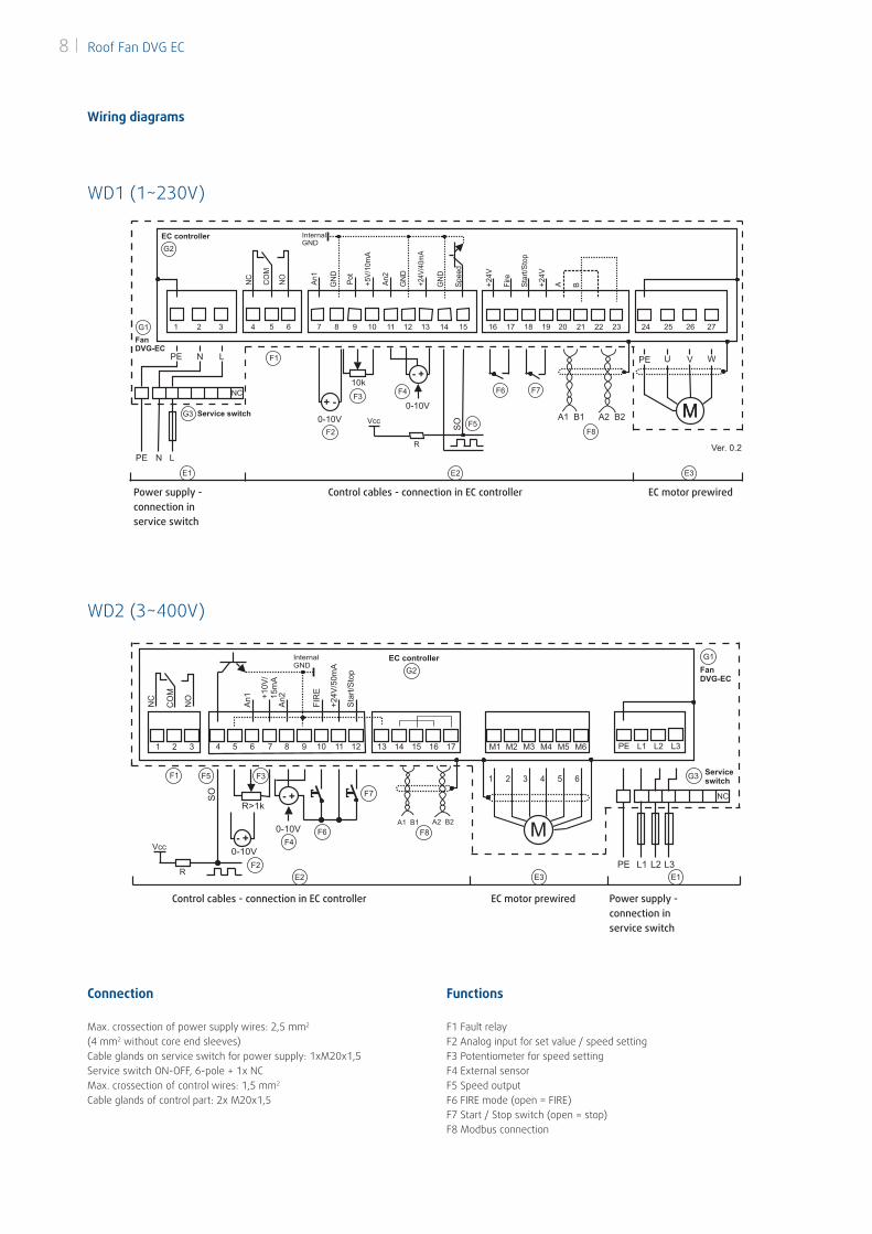
Wiring diagrams
Connection Functions
WD1 (1~230V)
WD2 (3~400V)
Power supply - connection in service switch
Power supply - connection in service switch
Control cables - connection in EC controller
Control cables - connection in EC controller
EC motor prewired
EC motor prewired
Max. crossection of power supply wires: 2,5 mm2 (4 mm2 without core end sleeves)Cable glands on service switch for power supply: 1xM20x1,5Service switch ON-OFF, 6-pole + 1x NCMax. crossection of control wires: 1,5 mm2
Cable glands of control part: 2x M20x1,5
F1 Fault relay F2 Analog input for set value / speed setting F3 Potentiometer for speed setting F4 External sensor F5 Speed output F6 FIRE mode (open = FIRE) F7 Start / Stop switch (open = stop) F8 Modbus connection
8 Roof Fan DVG EC
Roof Fan DVG EC 9
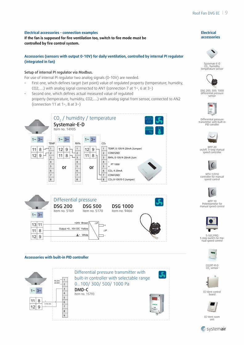
Electrical accessories - connection examplesIf the fan is supposed for fi re ventilation too, switch to fi re mode must be controlled by fi re control system.
Electrical accessories
Accessories (sensors with output 0-10V) for daily ventilation, controlled by internal PI regulator (integrated in fan)
Setup of internal PI regulator via Modbus. For use of internal PI regulator two analog signals (0-10V) are needed.• First one, which defi nes target (set point) value of regulated property (temperature, humidity,
CO2,…..) with analog signal connected to AN1 (connection 7 at 1~, 6 at 3~) • Second one, which defi nes actual measured value of regulated
property (temperature, humidity, CO2,…..) with analog signal from sensor, connected to AN2 (connection 11 at 1~, 8 at 3~)
11 812 9
1 TEMP, 0-10V/4-20mA (Jumper)
2 COM/GND
TEMP
3 RH%, 0-10V/4-20mA (Jumper)
4 -
5 +
6 CO2, 4-20mA
PT 1000
7 COM/GND
8
1
2
3
4
5
6
7
8 CO2, 0-10V/0-5 (Jumper)
12 911 8
RH%
1
2
3
4
5
6
7
8
12 911 8
CO2
CO2 / humidity / temperatureSystemair-E-DItem no. 14905
or or
% CO 2
°C°C
% CO 2
°C°C
% CO 2
°C°C
% CO 2
°C°C
CO2RT-R-DCO2 sensor
S-5EC/FRQ5 step switch for ma-
nual speed control
EC-Vent room unit
EC-Vent control board
Systemair-E-DCO2, humidity,
temperature sensor
MTP 10Potentiometer for
manual speed control
MTP 20on/off, 3-step manual
speed controller
MTV-1/010controller for manual
speed control
13 1111 812 9
+24V Brown+
-
Output +0...10V DC Yellow
White
Differential pressureDSG 200Item no. 5169
DSG 500Item no. 5170
DSG 1000Item no. 9466
% CO 2
°C°C
DSG 200, 500, 1000 differential pressure
sensor
Differential pressure transmitter with built-in
PID cotroller
Accessories with built-in PID controller
11 812 9
0-10V DC
+
-
6
7
IN 24VAC/DC
8
9
1
2
3
4
5
Differential pressure transmitter with built-in controller with selectable range 0...100/ 300/ 500/ 1000 PaDMD-CItem no. 15793
% CO 2
°C°C
10 Roof Fan DVG EC
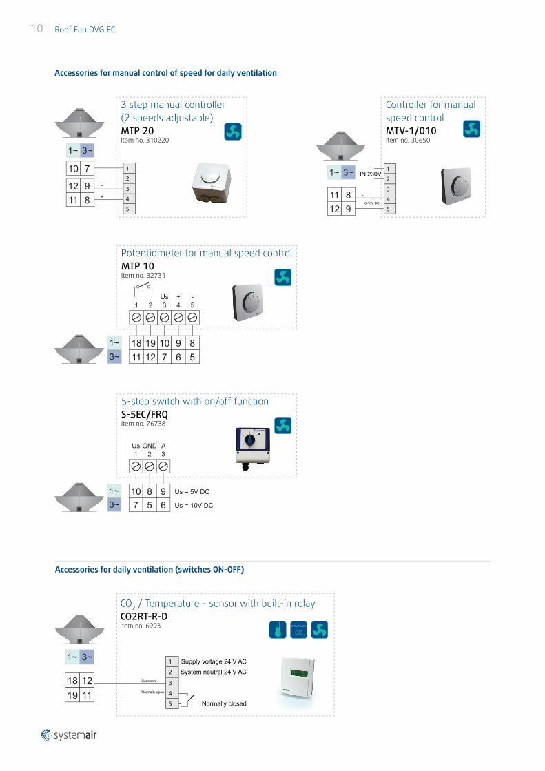
Accessories for manual control of speed for daily ventilation
Accessories for daily ventilation (switches ON-OFF)
Potentiometer for manual speed controlMTP 10Item no. 32731
3 4 5Us + -
1 2
10 9 818 197 6 511 12
% CO 2
°C°C
5-step switch with on/off functionS-5EC/FRQItem no. 76738
3Us
Us = 5V DC
Us = 10V DC
GND A1 2
910 867 5
18 1219 11
1 Supply voltage 24 V AC2 System neutral 24 V AC
3Common
4Normally open
5 Normally closed
% CO 2
°C°C
% CO 2
°C°C
% CO 2
°C°C
CO2 / Temperature - sensor with built-in relayCO2RT-R-DItem no. 6993
Controller for manual speed controlMTV-1/010Item no. 30650
% CO 2
°C°C
11 812 9
1
2IN 230V
0-10V DC
+
-
3
4
5
3 step manual controller (2 speeds adjustable)MTP 20Item no. 310220
% CO 2
°C°C
12 9
10 7
11 8
1
2-
+3
4
5
% CO 2
°C°C
Roof Fan DVG EC 11
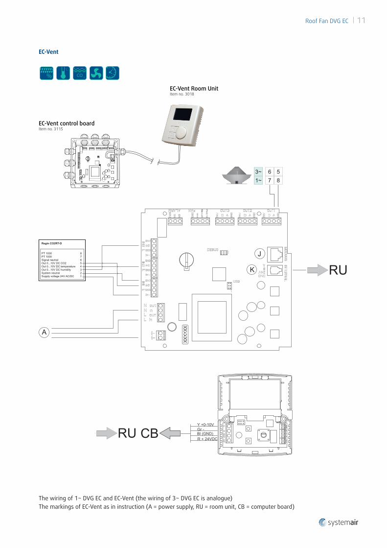
EC-Vent
The wiring of 1~ DVG EC and EC-Vent (the wiring of 3~ DVG EC is analogue)The markings of EC-Vent as in instruction (A = power supply, RU = room unit, CB = computer board)
EC-Vent control boardItem no. 3115
% CO 2
°C°C
% CO 2
°C°C
% CO 2
°C°C
% CO 2
°C°C
Regin CO2RT-D
PT 1000PT 1000Signal neutralOut 0...10V DC CO2Out 0...10V DC temperatureOut 0...10V DC humiditySystem neutralSupply voltage 24V AC/DC
87654321
Regin CO2RT-D
PT 1000PT 1000Signal neutralOut 0...10V DC CO2Out 0...10V DC temperatureOut 0...10V DC humiditySystem neutralSupply voltage 24V AC/DC
87654321
1~3~
76
85
% CO 2
°C°C
EC-Vent Room UnitItem no. 3018

www.systemair.com Syst
emai
r d.o
.o. ·
Janu
ary
2017
· E8
301