dunnet outfall - marine scotlandmarine.gov.scot/sites/default/files/06955_-_scottish... ·...
TRANSCRIPT

Stockton Drilling Ltd.
Dunnet OutfallProject Method Statement
Rev.A04
Page 3 of 63
TABLE OF CONTENTS
TABLE OF CONTENTS ....................................................................................................................... 3
1 INTRODUCTION ..................................................................................................................... 6
1.1 WHO ARE STOCKTON DRILLING .................................................................................... 6
2 PURPOSE OF DOCUMENT .................................................................................................... 7
3 DEFINITIONS & ABBREVIATIONS ........................................................................................ 7
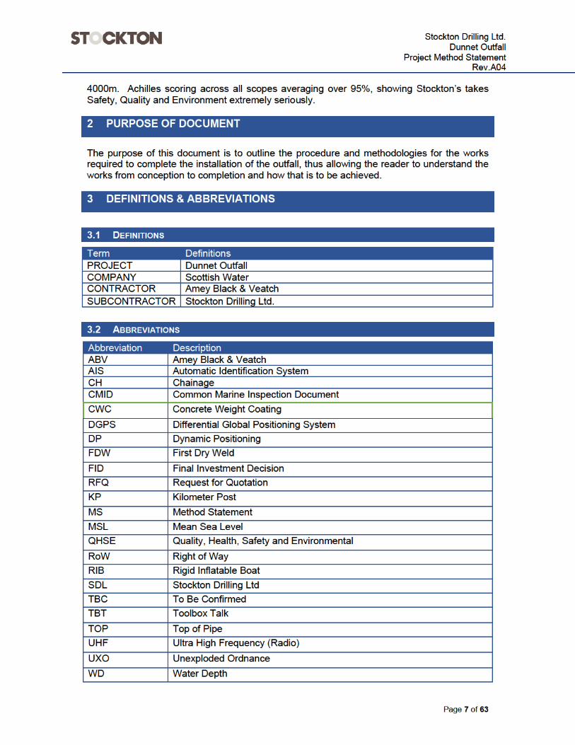
3.1 DEFINITIONS ............................................................................................................... 7
3.2 ABBREVIATIONS .......................................................................................................... 7
4 REFERENCE DOCUMENTS ................................................................................................... 8
4.1 REFERENCE DOCUMENTS COMPANY ......................................................................... 8
4.2 REFERENCE DOCUMENTS SUBCONTRACTOR ........................................................... 9
4.3 ADDITIONAL REFERENCES ......................................................................................... 10
5 PROJECT DESCRIPTION ..................................................................................................... 10
5.1 PROJECT INTRODUCTION ........................................................................................... 10
5.2 THE EXISTING OUTFALL ............................................................................................. 10
6 PROJECT CONSTRAINTS ................................................................................................... 11
6.1 THE SITE .................................................................................................................. 11
6.2 ACCESS TO THE SITE (ONSHORE) .............................................................................. 12
6.3 ACCESS TO THE SITE (OFFSHORE) ............................................................................ 12
6.4 DELIVERIES .............................................................................................................. 13
6.5 NOISE & VIBRATIONS ................................................................................................. 13
6.6 WORKING HOURS ...................................................................................................... 13
6.7 PARKING .................................................................................................................. 13
7 PROJECT PROGRAMME ..................................................................................................... 13
7.1 KEY DATES ............................................................................................................... 13
8 OBJECTIVES AND STRATEGIES ........................................................................................ 14
8.1 REACTIVE KPI’S: ....................................................................................................... 14
8.2 PROACTIVE KPI’S: ..................................................................................................... 14
8.3 SITE MONITORING AND MANAGEMENT ........................................................................ 14
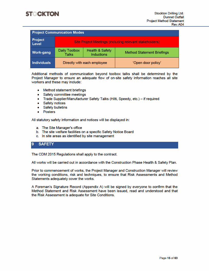
9 SAFETY ................................................................................................................................. 15
9.1 SITE AND LIFE SAVING RULES .................................................................................... 16
9.2 PPE ......................................................................................................................... 16
9.3 OCCUPATIONAL HEALTH ............................................................................................ 17
9.4 MONITORING ............................................................................................................. 17
9.5 SAFETY OF THE PUBLIC AND OCCUPIERS ................................................................... 17
9.6 PUBLIC NUISANCE ..................................................................................................... 17
9.7 PLANT INSPECTION AND OPERATOR TRAINING ............................................................ 18
Stockton Drilling Ltd.
Dunnet OutfallProject Method Statement
Rev.A04
Page 4 of 63
9.8 TEMPORARY WORKS ................................................................................................. 18
10 EMERGENCY PROCEDURES .............................................................................................. 18
11 ENVIRONMENT .................................................................................................................... 19
11.1 ENVIRONMENTAL CONTROLS ...................................................................................... 19
12 DRILLING FLUID .................................................................................................................. 19
13 DRILLING FLUID BREAKOUT ............................................................................................. 21
13.1 BREAKOUT ON LAND .................................................................................................. 21
13.2 DRILLING FLUID BREAKOUT UNDER WATER .................................................................. 22
14 DRILLING FLUID CONTROL DURING PUNCH OUT ........................................................... 22
15 QUALITY ............................................................................................................................... 23
16 SITE MANAGEMENT ............................................................................................................ 24
16.1 PROJECT ORGANOGRAM ........................................................................................... 24
16.2 RESPONSIBILITIES ..................................................................................................... 24
17 PLANT AND EQUIPMENT .................................................................................................... 27
17.1 ONSHORE SPREAD ..................................................................................................... 27
17.2 OFFSHORE SPREAD .................................................................................................. 27
18 SDL DETAILED WORKS PLANS & PROCEDURES ............................................................ 27
18.1 QA FORM 006 & 012 ACTIONS & RESPONSIBILITIES .......................................... 27
19 DIRECTIONAL DRILLING METHODOLOGY ....................................................................... 28
19.1 PILOT HOLE AND GUIDANCE ...................................................................................... 28
19.2 DRILL BIT POSITIONING .............................................................................................. 29
20 SCOPE OF WORKS .............................................................................................................. 30
20.1 OUTLINE ................................................................................................................... 30
20.2 WORKS SEQUENCING ................................................................................................ 31
20.3 PRE COMMENCEMENT OF THE WORKS ....................................................................... 31
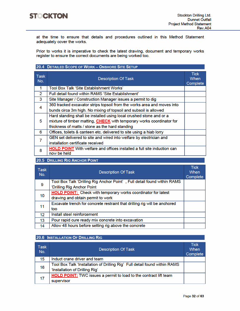
20.4 DETAILED SCOPE OF WORK – ONSHORE SITE SETUP .................................................. 32
20.5 DRILLING RIG ANCHOR POINT .................................................................................... 32
20.6 INSTALLATION OF DRILLING RIG ................................................................................. 32
20.7 DIRECTIONAL DRILLING .............................................................................................. 33
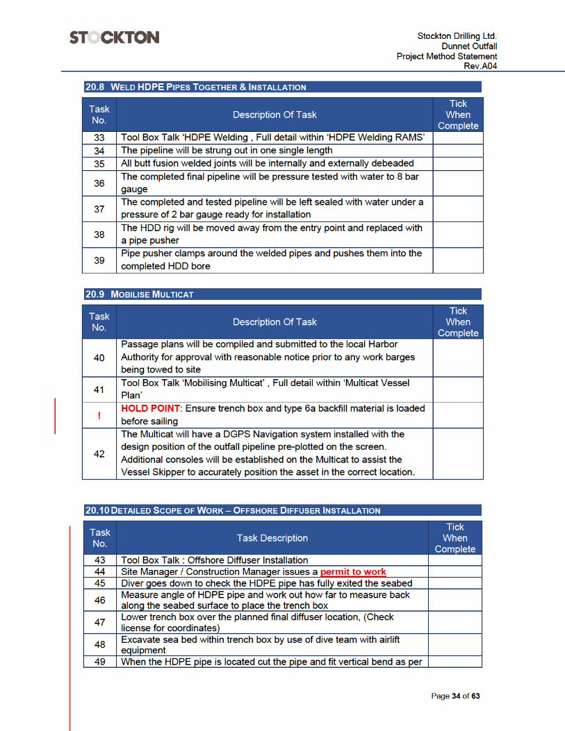
20.8 WELD HDPE PIPES TOGETHER & INSTALLATION ......................................................... 34
20.9 MOBILISE MULTICAT .................................................................................................. 34
20.10 DETAILED SCOPE OF WORK – OFFSHORE DIFFUSER INSTALLATION ............................... 34
20.11 REINSTATEMENT ....................................................................................................... 35
21 HOUSE KEEPING ................................................................................................................. 35
22 QC RECORDS AND PROJECT HANDOVER ....................................................................... 35
22.1 COMPLETION DEFINITION............................................................................................ 35
22.2 FINAL CLEAN ............................................................................................................ 36
22.3 CORRECTING DEFECTS .............................................................................................. 36
23 CHANGE CONTROL ............................................................................................................. 36

Stockton Drilling Ltd.
Dunnet OutfallProject Method Statement
Rev.A04
Page 5 of 63
24 RISK ASSESSMENT ONSHORE .......................................................................................... 37
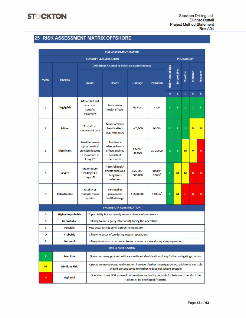
25 RISK ASSESSMENT MATRIX OFFSHORE ......................................................................... 43
26 RISK ASSESSMENT OFFSHORE SCOPE ........................................................................... 44
27 HDD RISK MITIGATION REGISTER .................................................................................... 58
........................................................................................................................................................... 59
28 TEMPORART WORKS SCHEDULE ..................................................................................... 62
APPENDIX A - FOREMANS SIGN ON SHEET ................................................................................. 63
Stockton Drilling Ltd.
Dunnet OutfallProject Method Statement
Rev.A04
Page 6 of 63
1 INTRODUCTION
Stockton Drilling Ltd have been invited by Amey, Black & Veatch to provide early contractor involvement services to assist with the design and proposed construction methodology of the Dunnet Outfall.
1.1 WHO ARE STOCKTON DRILLING
Our Company
Stockton - is a privately owned Limited company specialising in horizontal directional drilling and open cut pipeline installation. Our Location
Head office is based in Wakefield (West Yorkshire) and our plant yard is based in Barnsley (South Yorkshire), 10 miles from our Head Office. We operate predominately throughout the UK and Europe. Our People
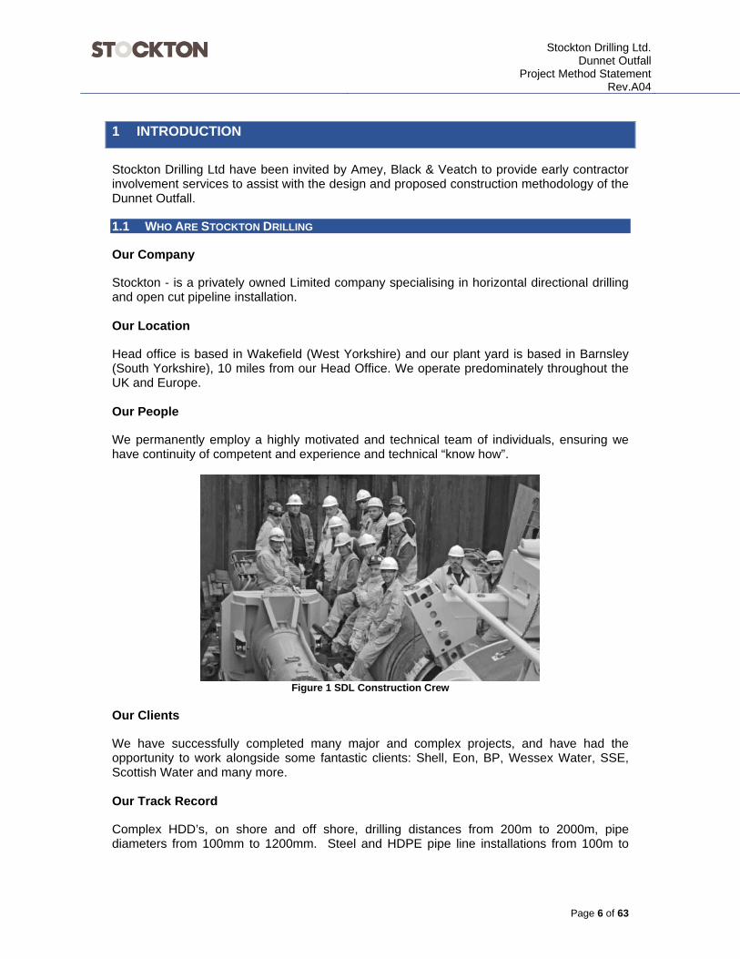
We permanently employ a highly motivated and technical team of individuals, ensuring we have continuity of competent and experience and technical “know how”.
Figure 1 SDL Construction Crew
Our Clients
We have successfully completed many major and complex projects, and have had the opportunity to work alongside some fantastic clients: Shell, Eon, BP, Wessex Water, SSE, Scottish Water and many more. Our Track Record
Complex HDD’s, on shore and off shore, drilling distances from 200m to 2000m, pipe diameters from 100mm to 1200mm. Steel and HDPE pipe line installations from 100m to


Stockton Drilling Ltd.
Dunnet OutfallProject Method Statement
Rev.A04
Page 11 of 63
6 PROJECT CONSTRAINTS
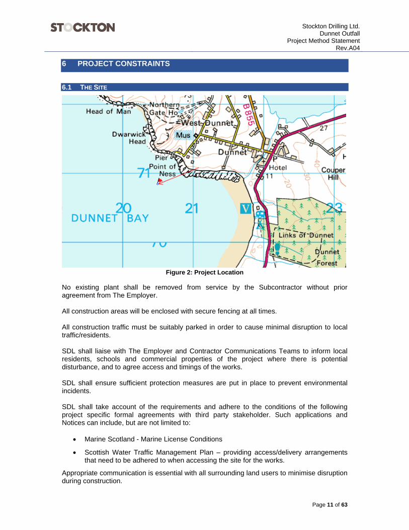
6.1 THE SITE
Figure 2: Project Location No existing plant shall be removed from service by the Subcontractor without prior agreement from The Employer. All construction areas will be enclosed with secure fencing at all times. All construction traffic must be suitably parked in order to cause minimal disruption to local traffic/residents. SDL shall liaise with The Employer and Contractor Communications Teams to inform local residents, schools and commercial properties of the project where there is potential disturbance, and to agree access and timings of the works. SDL shall ensure sufficient protection measures are put in place to prevent environmental incidents. SDL shall take account of the requirements and adhere to the conditions of the following project specific formal agreements with third party stakeholder. Such applications and Notices can include, but are not limited to:
Marine Scotland - Marine License Conditions
Scottish Water Traffic Management Plan – providing access/delivery arrangements that need to be adhered to when accessing the site for the works.
Appropriate communication is essential with all surrounding land users to minimise disruption during construction.
Stockton Drilling Ltd.
Dunnet OutfallProject Method Statement
Rev.A04
Page 13 of 63
6.4 DELIVERIES
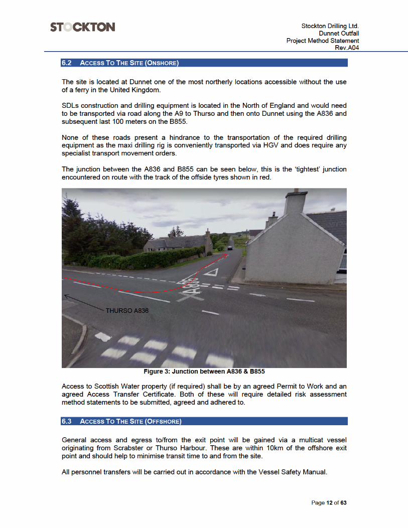
The works is accessed via A9 > A836 > B855. SDL shall ensure that any vehicular movements to and from the site of the works are planned and managed with due consideration to local residents and road users. Deliveries shall be between 08:00hrs and 18:00hrs and will require to have SDL attendance to manage the safe offloading of materials. A delivery plan is to be in place detailing where the unloading (Lifting RAMS) will take place and the protection methods used.
6.5 NOISE & VIBRATIONS
Noise and vibration restrictions if any will be detailed in the Marine License.
6.6 WORKING HOURS
There is no restriction on the working hours at this location.
SDL intend to work 12 hours a day 7 days a week, 07:00hrs to 19:00hrs.
6.7 PARKING
Provision of parking for site personnel and visitors is the responsibility of SDL. The Site Compound shall be made at a sufficient size to accommodate the vehicles attending the site in accordance with the Subcontractor’s Traffic Management Plan. Parking outside the Subcontractor’s compound area should not adversely affect the local residents access to their properties without prior agreement by the residents affected. In general a HDD compound is 60m x 60m and can be altered to some extent to fit the contours of the land, however the footprint of 3600m2 is hard to reduce safely.
7 PROJECT PROGRAMME
7.1 KEY DATES
Start On Site : 08/07/2019
Completion : 21/01/2020

Stockton Drilling Ltd.
Dunnet OutfallProject Method Statement
Rev.A04
Page 14 of 63
8 OBJECTIVES AND STRATEGIES
Stockton has responsibilities to all stakeholders in the project. We monitor and build upon previous lessons learned through the use of KPI’s. Stockton record two kinds of KPI’s to help us build a safer and enhanced work force; these are:
8.1 REACTIVE KPI’S:
Fatality Lost Time Accident – LTA Medical Treatment Case – MTC Needs hospital / GP assistance off site First Aid Case – FAC Restricted Work Case – RWC Able to work on minor duties instead of those normally
employed to undertake Environmental incidents
8.2 PROACTIVE KPI’S:
Safety documentation delivered on time Toolbox Talks completed as planned Induction Training completed for all persons Inspections and Audits completed as planned Near misses / Safety observation reports / cards Daily Walk and Talk Cards Number of inspections completed Contractor hours worked
8.3 SITE MONITORING AND MANAGEMENT
The following monitoring will be conducted on site, as required:
Hazard reporting Excavation / Temporary Works Inspections Daily preventative maintenance records for operated plant Periodic inspections in accordance with LOLER and PUWER Weekly HSE and Welfare Inspections Weekly Hazard Spotting Inspections Stockton’s Management HSQA Audits
High standards of communication with the workforce are to be developed through regular toolbox talks/ task-briefings conducted by our Site Project Manager. Stockton’s will require all employees and subcontractors to attend daily safety toolbox talks prior to commencing works on site. We shall maintain a written record of attendance (toolbox talk record sheet) for these talks for the duration of the project within the project site folders for inspection.


Stockton Drilling Ltd.
Dunnet OutfallProject Method Statement
Rev.A04
Page 17 of 63
activities
Hearing Protection EN352 PART 1 As required If a conversation cannot be held ear protection is mandatory
Gloves EN420 At all times Must be on person at ALL times
9.3 OCCUPATIONAL HEALTH
None of the individual activities covered by this Method Statement require our operatives to undergo health surveillance.
9.4 MONITORING
All personnel working on site will be inducted and familiarised with SDL and ABV site rules. Prior to commencing works on site the training and competency certificates for personnel will be checked and approved by SDL site management. In addition, the following monitoring will be conducted on site, as required:
Hazard reporting Excavation Inspections Daily preventative maintenance records for operated plant Periodic inspections in accordance with LOLER and PUWER Weekly HSE and Welfare Inspections Weekly Hazard Spotting Inspections SDL Management HSEQ Audits
9.5 SAFETY OF THE PUBLIC AND OCCUPIERS
The public and other occupiers will be excluded from the works by secure fencing and warning signs. If deemed necessary security cameras/ guarding will be used during non-working hours.
9.6 PUBLIC NUISANCE
SDL shall endeavor at all times during the works to minimise disruption to the public. In the event that any debris is deposited on public roads during deliveries, SDL will organise road sweeping immediately and shall regularly monitor road conditions.


Stockton Drilling Ltd.
Dunnet OutfallProject Method Statement
Rev.A04
Page 20 of 63
To transport cuttings from the drill face through the annular space towards the surface
Lubricate the drill string during drilling phases and HDPE strings during pull back Cooling the reamers (cutting tools) Hole stabilization Creation of a filter cake against the wall of the hole to minimize the risk of loss of
drilling fluid or influx of groundwater penetration into the borehole
The characteristics of drilling fluid, especially the viscosity can be adjusted during the drilling phases by changing the structure of the composite.
The drilling fluid consists of a low concentration bentonite – water mixture. Depending on the formation to be drilled through, the concentration of is between 13 litres (30kg) and 35 litres (80kg) of dry bentonite clay per m3 of water.
The use of bentonite has a number of benefits:
It is a natural material, so no chemical
It is recyclable
It is on the PLONOR list, so discharge is not a danger to the environment
However, owing to the long length, the total volume of fluids is considerable, but owing to the low concentration the total amount of bentonite is limited.
However, even though the material is not harmful to the environment, reduction is always sought. To further minimize the total discharge of bentonite the forward reaming option has been developed.
The system consists of a generator, combo mix/recycling unit, EW pump (high pressure pump), booster pump, BBA pumps (for drilling fluid), holding tanks, mud pits, return line and basins (for storage of drilling fluid and cuttings). SDL will arrange for fresh water to be delivered to the drilling location. This will be either from a nearby river or provider of water and stored in holding tanks to be used for mixing. The fresh water will be mixed with Bentonite until the desired values for the composite are reached. From there, the drilling fluid will be transported by the EW pump which is connected on the rig. Normally a capacity of 30 to 40m³ per hour is needed during drilling phases. In case of drilling fluid loss, a capacity of 60 to 70m³ is required. Mud pits, situated at the entry point of the HDD, create a first “holding” possibility for drilling fluid. From there, the drilling fluid will be transported by BBA pumps to the recycling unit to separate drilling fluid from cuttings. Recycled drilling fluid will be stored in tanks to be used in each drilling phase. Parameters of drilling fluid will be monitored and registered on a regular base throughout the drilling phases. Monitoring includes:
Registering amount of Bentonite added to the drilling fluid;
Measuring viscosity of drilling fluid and drilling sand;

Stockton Drilling Ltd.
Dunnet OutfallProject Method Statement
Rev.A04
Page 21 of 63
Measuring percentage of sand in drilling fluid and drilling sand;
Measuring specific weight of drilling fluid and drilling sand.
13 DRILLING FLUID BREAKOUT
Drilling fluid (bentonite) can sometimes break out of the bore in case of highly fissured clay, gravels or where there are large interconnected fissures in the ground. Breakouts may also occur where man made features are present (e.g. old SI boreholes). In the event of egress of drilling fluid from the bore it is only likely to reach ground level where there is a continuous path available to the surface. The risk of a bentonite breakout during drilling cannot be fully assessed beforehand however any decrease in the mud volume returning to the entry pit will trigger the need for personnel to closely monitor the area around the drilling head. For this reason a close watching brief during drilling activities and a detailed contingency plan is essential to ensure that any drilling fluid breakout is contained, bunded and pumped back to the entry pit with minimum disturbance to the surrounding environment. Drilling mud breakouts are only likely to happen when the fluid is under pressure, so during drilling, site monitoring will be carried out by dedicated personnel. The site to be monitored will include an area of 100m in front or behind the drill head and 25m either side of the centre line of the drill route. The site will be divided into three areas which will be checked regularly. Records shall be maintained of inspections. In addition, a downhole annular pressure sensor will be used during drilling. The maximum allowable annular pressure according to the design calculations will be plotted on screen with an alarm sounding if we get to 90% of that allowable limit. If this happens we stop drilling and retract the drilling assembly until the blockage has been cleared before continuing to drill. It is proposed to use an advanced formula drilling fluid, a proprietary blended product using high-yielding sodium bentonite. The drilling fluid forms an impermeable filter cake around the drill annulus due to the alignment of the clay platelets. Although drilling mud as used in HDD is environmentally friendly, it may spread over a large area and cause nuisance. In certain areas the sealing effect of the mud may cause problems when spreading over a surface. It must be agreed with the client, before the drilling operations start, which actions must be taken in case of a break out. Below listed are possible actions.
13.1 BREAKOUT ON LAND
1. Report immediately to drilling control cabin using site two-way radio
2. Stop drilling immediately
3. Contain the bentonite by constructing a bund with sandbags

Stockton Drilling Ltd.
Dunnet OutfallProject Method Statement
Rev.A04
Page 22 of 63
4. Recover the bentonite from the bund by using 4” pump sets and 4” hoses
5. Discharge the bentonite into the recycling pit for recycling
6. Watch the area closely to check if breakout channel has sealed when pumping.
7. Pump lost circulation material or cement grout and allow to swell in the fracture
8. Continue pumping bentonite after waiting for lost circulation material to work according to manufacturers recommendations. If fracture cannot be sealed, continue to recover bentonite from the bunded area using 4” pumps
9. For containment of break outs on land, sandbags will be stored where they can be easily and quickly brought to the breakout point. Personnel monitoring the site will be equipped with radios for instant communication with the driller.
13.2 DRILLING FLUID BREAKOUT UNDER WATER
1. Any loss of drilling fluid in the entry pit is reported immediately to the driller
2. Stop drilling immediately
3. Pump lost circulation material to seal fissure
4. Wait for the lost circulation material to swell in the fracture
5. Pump a mixture of ‘Pure Bore’ to see if circulation can be maintained.
6. If not, repeat the process with lost circulation material.
7. If the fracture cannot be sealed, either a grout plug of cement will be pumped at the end of the bore, or the drilling assembly will be withdrawn for a distance and a new profile drilled to avoid the problem area. This is dependent upon the rate of fluid loss and the geology encountered.
Fast and efficient reporting is an essential component of the contingency plan. Emergency telephone numbers are to be available for all the appropriate parties. The site manager / drilling manager is to complete the breakout report as soon as practicable after the completion of the clean up.
14 DRILLING FLUID CONTROL DURING PUNCH OUT
To prevent bentonite drilling fluid from entering the ocean SDL propose to complete the initial pilot hole of the bore alignment to ‘stop short’ of punching out on the sea bed. This will be achieved by monitoring the distance and cuttings coming back from the cutting head. At around chainage 845m the drill head will leave the bedrock and enter the sand that makes up the seabed deposits. At this point we will cease drilling forwards and trip back to surface at the onshore HDD drilling entry point We will then equip the drill head with a reamer to widen the hole; This will be rotated and pushed into the bore using bentonite to aid its advancement, An MMO will be used to monitor for Marine Mammal activity during the drilling of this last section. If dolphins are present within 500m of the breakout area work will halt until the area

Stockton Drilling Ltd.
Dunnet OutfallProject Method Statement
Rev.A04
Page 23 of 63
is deemed as not to have Marine Mammals present by the MMO. At which point works will proceed. When the reamer reaches the end of the bore SDL will stop running bentonite through the drill string to the reamer. We will continue rotating the reamer and advance the final 25m using fresh water. This will contain the bentonite in the drilled bore and prevent a bentonite discharge into the sea.
15 QUALITY
It is the policy of Stockton to provide and execute all Works to a high standard of quality, and these will be delivered as defined in our Quality Plan and Inspection and Test Plan. Quality shall be performed during all Contract Phases:
Planning Design Procurement Installation Commissioning
Stockton will prepare an Inspection and Testing Plan (ITP), for the scope of Works, according to the content of the contract identified. The ITP will include but not limited to:
Inspection and Test Audit Plans Risk managed components Names of Subcontractors Planning documents of QA


Stockton Drilling Ltd.
Dunnet OutfallProject Method Statement
Rev.A04
Page 25 of 63
Ensuring that health and safety is monitored and reported on and that policies are reviewed and updated as necessary
Ensuring site safety and that everyone (employees and contractors) is fully aware of their health and safety responsibilities
Ensuring that suitably competent and trained persons are appointed and that good working practices are adhered to
Ensuring training is available for all staff Encouraging health and safety communications across the organisation
The Project Manager is responsible to, and shall report to the Managing Director and is responsible for:
Site safety and shall ensure that everyone is aware of their safety responsibilities, are working to safe systems of work and are competent for the work activities undertaken
Ensuring that necessary method statements are written for site work, and that the degree of supervision, safe systems of work and competencies are available to ensure that staff maintain a high degree of site health and safety
Carrying out the necessary preliminary and specific risk and COSHH assessments and ensuring that they are distributed to the project team and all site staff
Monitoring adherence to the Health & Safety Plan and the Organisation’s Health & Safety Policy
Ensuring site inductions are carried out in accordance with the Organisation's standards
Encouraging health and safety communications throughout the duration of the works between him/herself the, the Construction Manager, project team and subcontractors
Ensuring that good site housekeeping discipline, which shall include correct disposal of all waste material at the end of each working shift
Ensuring that adequate first aid and firefighting equipment is available at all times Prompt investigation, recording and reporting of accidents, incidents and safety
defects Ensuring that (or undertaking) the necessary Site Safety Inspections and Audits are
conducted and that the findings are acted upon Ensuring that any work being carried out does not hinder any other contractors by
blocking escape routes, fire equipment, pedestrian routes and traffic routes or jeopardize the health and safety of other contractors in any way
Liaising with the Health & Safety Executive, Environment Agency and other external bodies
The Site Superintendent and or Construction Manager is responsible to, and shall report to the Project Manager and is responsible for:
Ensuring adherence to Method Statements, the Health & Safety Plan and the Organisation’s Health & Safety Policy
Implementing the health and safety induction, which all site personnel and visitors must attend. A record of this must be retained

Stockton Drilling Ltd.
Dunnet OutfallProject Method Statement
Rev.A04
Page 26 of 63
Ensuring that staff are given site briefings covering detail of fire escape routes, fire drills and assembly points on site
Encouraging health and safety communications throughout the duration of the works between him/herself the project team and subcontractors
Ensuring that good site housekeeping discipline, which shall include correct disposal of all waste material at the end of each working shift
Ensuring that adequate first aid and firefighting equipment is available at all times Recording and reporting of accidents, incidents and safety defects and reporting of
these to the Project Manager Informing the Project Manager of specific risk management issues such as COSHH,
noise, work equipment, method statements etc. Carrying out as necessary Site Safety Inspections and ensuring that the findings are
made known to Project Manager Ensuring that all site plant, tools and equipment are of the appropriate type,
adequately maintained and operators are competent Ensuring that all plant, tools and equipment and materials is delivered and handled in
a safe manner from delivery to installation Ensuring, with respective line managers, that any work being carried out does not
hinder any other contractors by blocking escape routes, fire equipment, pedestrian routes and traffic routes or jeopardize the health and safety of other contractors in any way
Encouraging Employees and Contractors to make suggestions to improve health and safety on site
All Employees
Ensure familiarity and adherence to the Organisations Health & Safety Policy Observe all safety rules and codes of practice Ensure the appropriate safety equipment (PPE) is worn and appropriate safety
devices are used where there is risk of injury Conform to appropriate instructions from those with responsibility for health and
safety Report to Project Manager/Construction Manager any observed accidents and
damage to property or equipment irrespective of whether persons are injured, using the appropriate Accident and Incident Form
Report to Project Manager/Construction Manager all accidents to themselves whilst at work
Be encouraged to make suggestions to improve company health and safety on site to the Project Manager/Construction Manager
Report all hazards to Project Manager/Construction Manager When on customer/client site/premises, conform to the required signing on/off
procedures and safety rules When on customer/client site/premises, conform to the required accident or near miss
procedures Make themselves familiar with the fire and evacuation procedures

Stockton Drilling Ltd.
Dunnet OutfallProject Method Statement
Rev.A04
Page 28 of 63
Thus it is a simple task to identify if tasks are becoming critical or if any particular actions have been delayed.
19 DIRECTIONAL DRILLING METHODOLOGY
19.1 PILOT HOLE AND GUIDANCE
After the rig-up is completed, the HDD will commence. Drilling mud/fluid, consisting of a mixture of water and bentonite clay will be pumped down the drill string to break up and flush the material in front of and around the jet bit and flow back via the drilled hole to the mud pit at the entry site. An optional part of the process is the use of a recycling unit. The drilling slurry (bentonite mud and cuttings) will be transported towards the recycling unit via a mud pump. In the recycling unit the cuttings will be separated from the drilling slurry, allowing the drilling mud to be reused. The drilling mud:
Carries the cuttings out of the borehole; Stabilises the borehole; Prevents cross contamination of sea water on the land section; and Lubricates the drill string.
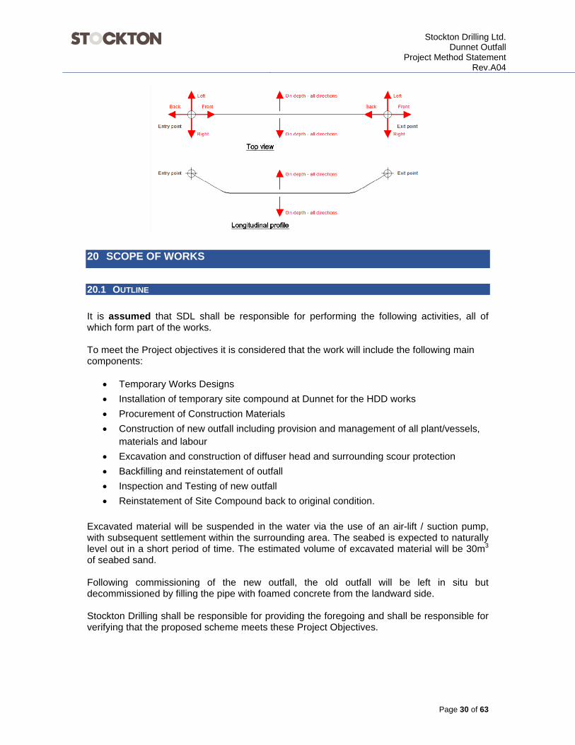
The pilot holes will be drilled using a 250 tonne pull force HDD rig with 90kNm torque. The drilling rig uses 6- 5/8”FH drill pipes in 9.6 meter lengths. A 12 ½’’ HDX TCI bit will be utilized with a 8’’ mud motor, shock sub and gyro as detailed: The mud motor will have a pre-set bend two metres behind the drill bit, to enable it to be steered. Behind this a downhole optical gyroscope is assembled together with a shock sub. This assembly will be drilled through the ground to follow the predetermined profile trajectory towards the predetermined exit point. Directional control is accomplished by rotating the drill string to steer a bent housing on the downhole assembly. If a change in direction is required, the drill string is rotated, changing the bent housing to the desired orientation. Periodic surface readings will be taken along the drill line to monitor the position of the drill head during the drilling operation. Just behind the drill head a sensor is located, which transmits a signal. This signal provides the surveyor with the receiver to locate the exact position of the drill head and advise the driller of the drilling line and steering requirements. To reduce drilling mud losses on the seabed it is envisioned that the pilot hole will be short stopped and retracted.

Stockton Drilling Ltd.
Dunnet OutfallProject Method Statement
Rev.A04
Page 30 of 63
20 SCOPE OF WORKS
20.1 OUTLINE
It is assumed that SDL shall be responsible for performing the following activities, all of which form part of the works. To meet the Project objectives it is considered that the work will include the following main components:
Temporary Works Designs
Installation of temporary site compound at Dunnet for the HDD works
Procurement of Construction Materials
Construction of new outfall including provision and management of all plant/vessels, materials and labour
Excavation and construction of diffuser head and surrounding scour protection
Backfilling and reinstatement of outfall
Inspection and Testing of new outfall
Reinstatement of Site Compound back to original condition.
Excavated material will be suspended in the water via the use of an air-lift / suction pump, with subsequent settlement within the surrounding area. The seabed is expected to naturally level out in a short period of time. The estimated volume of excavated material will be 30m3 of seabed sand. Following commissioning of the new outfall, the old outfall will be left in situ but decommissioned by filling the pipe with foamed concrete from the landward side. Stockton Drilling shall be responsible for providing the foregoing and shall be responsible for verifying that the proposed scheme meets these Project Objectives.

Stockton Drilling Ltd.
Dunnet OutfallProject Method Statement
Rev.A04
Page 31 of 63
20.2 WORKS SEQUENCING
The numbered list below is a high level overview of the envisaged works sequencing, these points are then explored in detail within the next section of this document.
1. Onshore site establishment, Install site offices, welfare.
2. Excavate at HDD entry point for the HDD anchor block and construct.
3. Install HDD rig at entry point.
4. Directional drill the required profile circa 750m.
5. Mobilise multicat to offshore exit point.
6. Weld HDPE SDR11 pipes onshore into one continuos length, set on temporary rollers. (It is possible to have more than one string of pipes to suit the land available, but every butt weld takes time and thus presents added risk in borehole collapse).
7. Pressure test HDPE pipeline
8. Upon completion of HDD bore move maxi rig away from entry point and install pipe pusher.
9. Push pipe into bore from onshore entry point, if required weld pipeline strings progressively together.
10. Post pipeline install, install diffuser from multicat using diver intervention.
20.3 PRE COMMENCEMENT OF THE WORKS
All personnel must be inducted onto the project, non-working visitors may be escorted around site by a Stockton manager if deemed appropriate. Prior to any activity all personnel involved will familiarise themselves with the site layout, access and egress. All personnel shall make themselves aware of the restricted or ‘out of bounds’ areas. Prior to commencement of related works the location of Muster Points will be identified and a ‘dry run’ emergency evacuation procedure shall be conducted. Prior to commencement of the activity ‘Permits to Work’ will be raised as/ where appropriate, or formal consent to proceed is given by the ABV representative. Reference shall be made to all available statutory public utility and clients service plans and layouts. Pegs and notices shall be set out to identify all relevant service positions. Immediately prior to commencement of works outlined in this Method Statement, (and at regular intervals thereafter) the Project Manager or other appointed supervisor will inspect the site and preview the activities, methods and risks with regard to the prevailing conditions


Stockton Drilling Ltd.
Dunnet OutfallProject Method Statement
Rev.A04
Page 36 of 63
are required to be completed, prepared and supplied to the Employer one month before the Completion Date (completion date) for the whole of the works:
H&S File
As Built drawings have been submitted to the Employer
Warranty Certification
That all Defects have been captured by the Subcontractor and a programme of works has been agreed by the Contractor, and The Employer’s Asset Planner and Customer Service Delivery Team Leader
The Acceptance Criteria has been achieved and evidenced.
22.2 FINAL CLEAN
The working area should be left in a clean and tidy condition, all new structures should be free of construction related debris, equipment and surplus materials etc.
22.3 CORRECTING DEFECTS
The defects date and the defects correction period shall be as stated in the Subcontract Data.
Defects shall be corrected prior to covering up the apparatus.
Defects on road reinstatements, including street furniture are considered to have Health & Safety consequences and shall be rectified as soon as practicable.
23 CHANGE CONTROL
Any deviation to this method statement shall take place once agreed between SDL and client and formally recorded.

Stockton Drilling Ltd.
Dunnet OutfallProject Method Statement
Rev.A04
Page 37 of 63
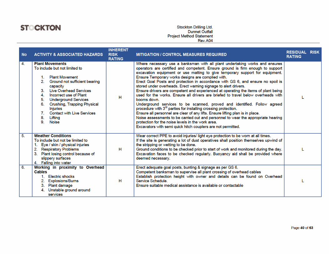
24 RISK ASSESSMENT ONSHORE


Stockton Drilling Ltd.
Dunnet OutfallProject Method Statement
Rev.A04
Page 44 of 63
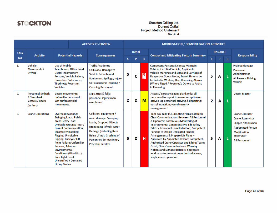
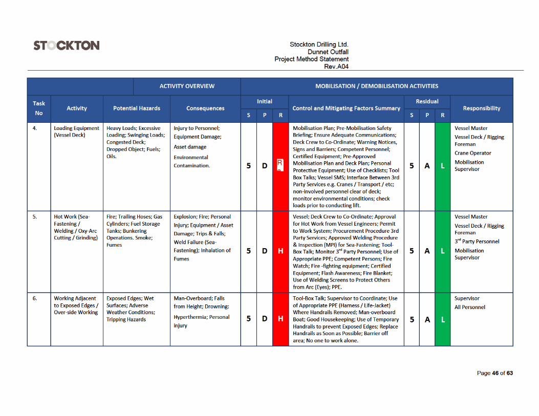
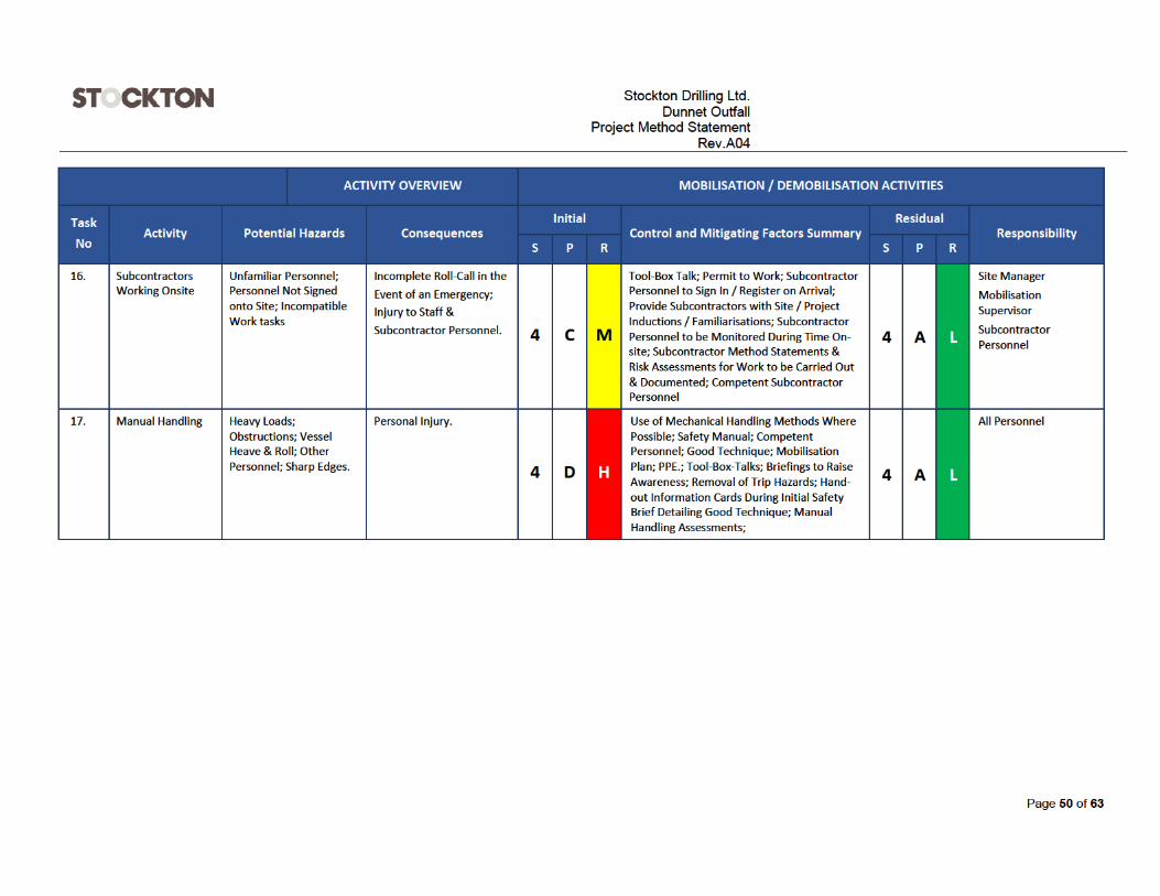
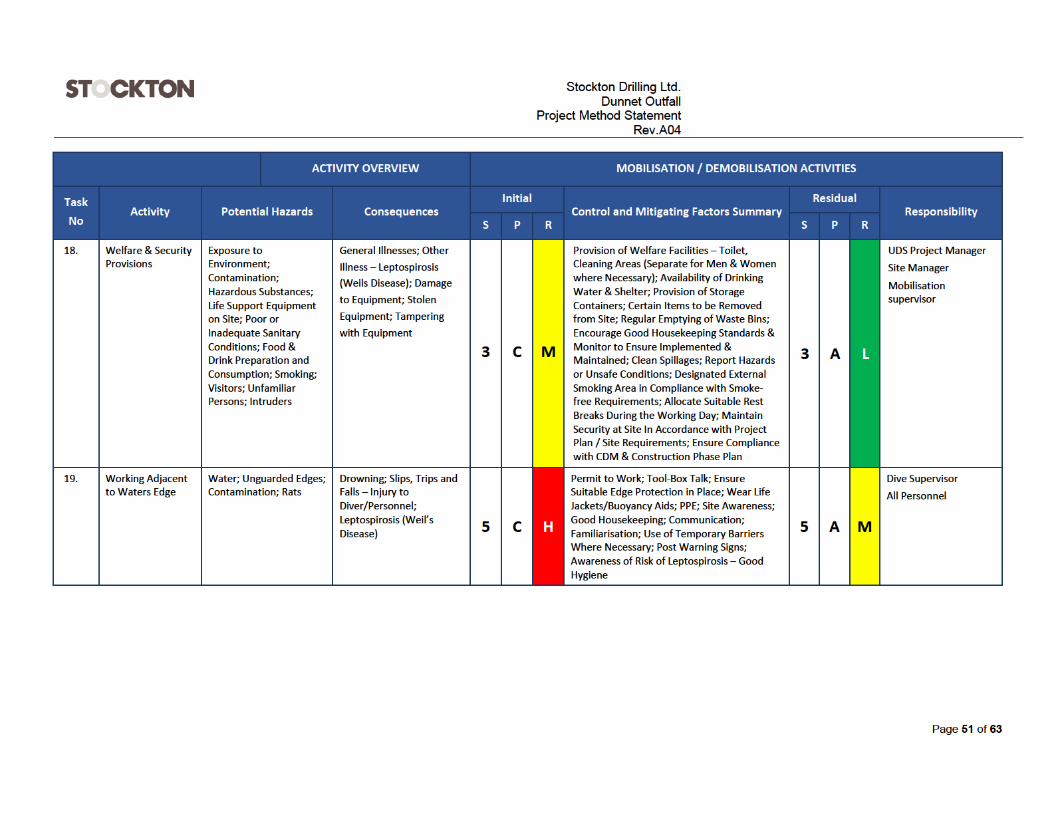
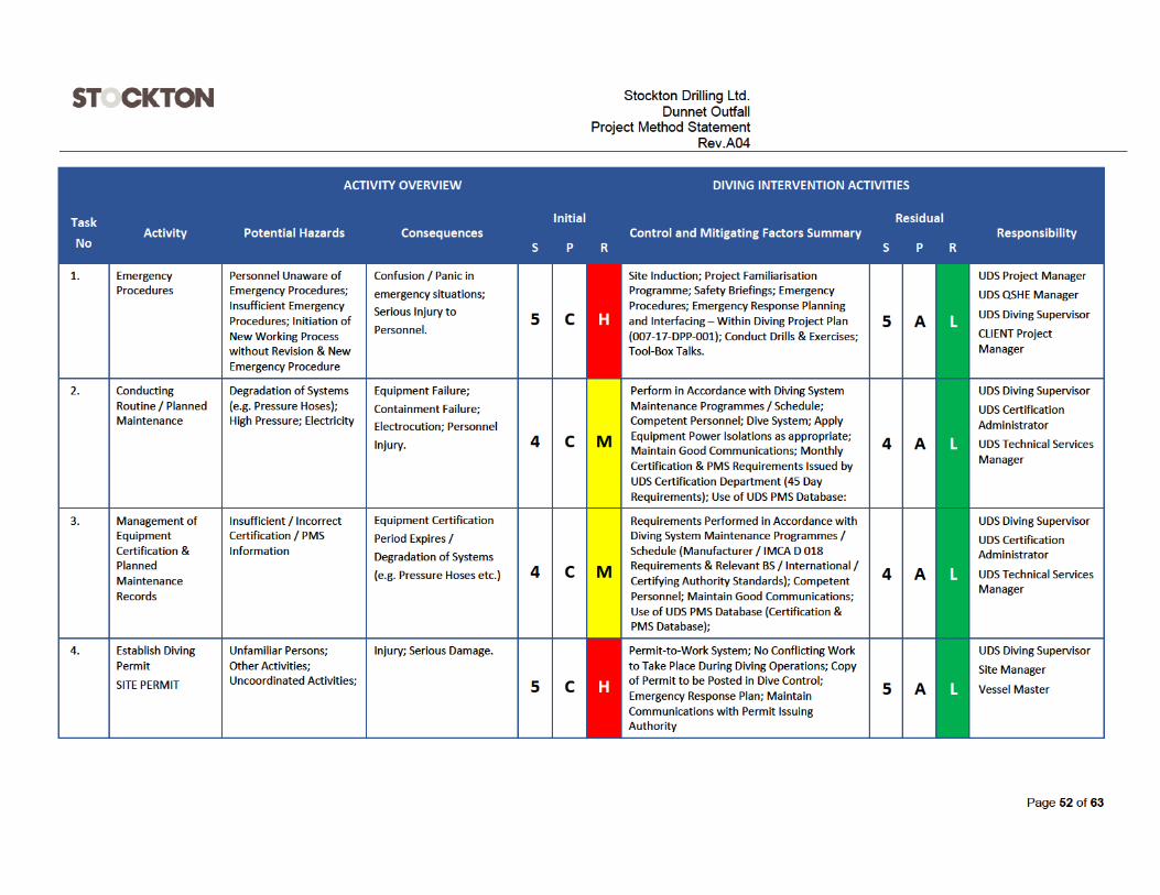
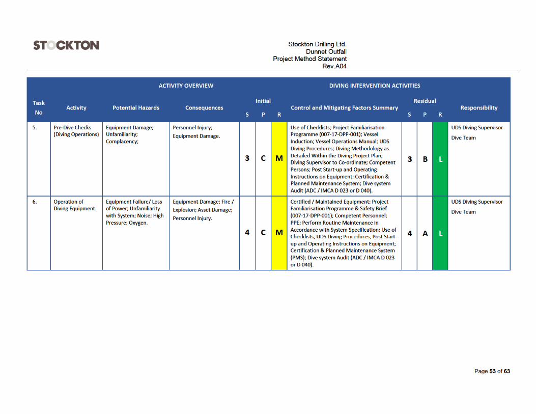
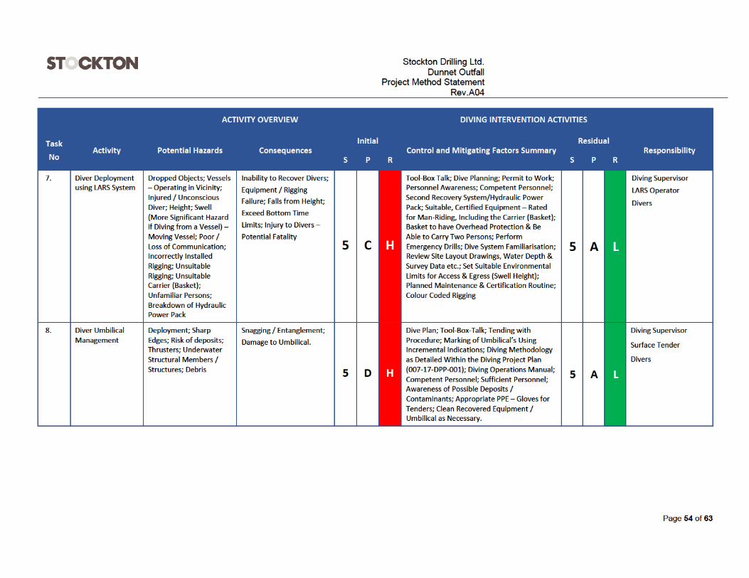
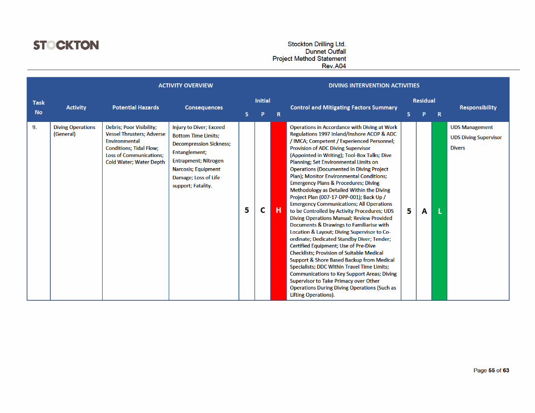
26 RISK ASSESSMENT OFFSHORE SCOPE


Stockton Drilling Ltd.
Dunnet OutfallProject Method Statement
Rev.A04
Page 58 of 63
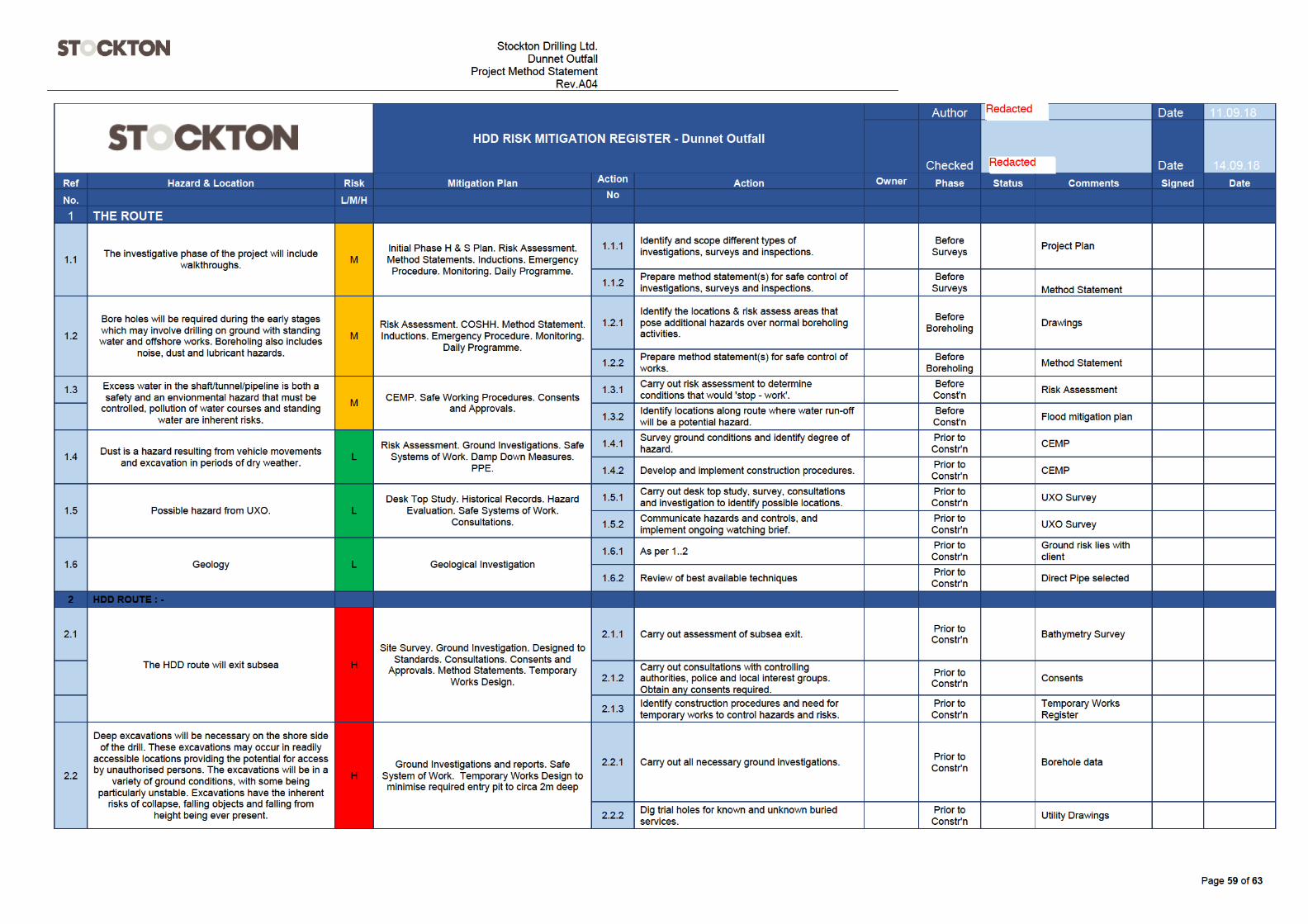
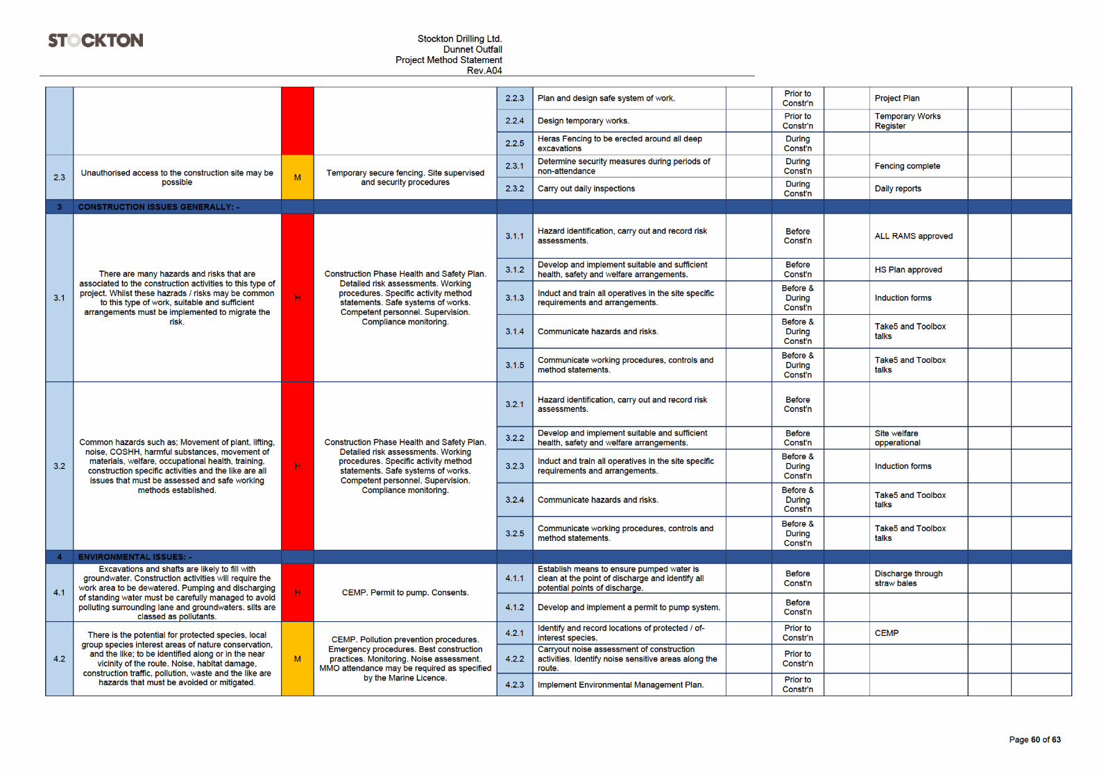
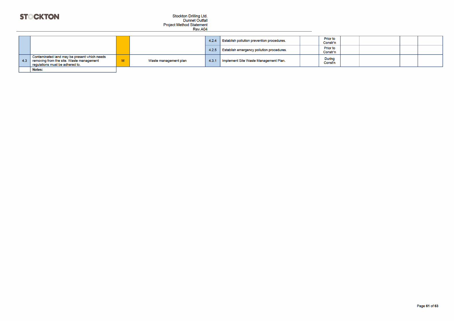
27 HDD RISK MITIGATION REGISTER
This page has been left intentionally blank