dulcometer®, compact controller, measured variable...
TRANSCRIPT
DULCOMETER®, Compact ControllerMeasured variable: conductive conductivity
Assembly and operating instructions
A1700
EN
Part no.: 985092 BA DM 209 08/15 EN
Please carefully read these operating instructions before use. · Do not discard.The operator shall be liable for any damage caused by installation or operating errors.
The latest version of the operating instructions are available on our homepage.
General non-discriminatory approach In order to make it easier to read, thisdocument uses the male form in grammat‐ical structures but with an implied neutralsense. It is aimed equally at both men andwomen. We kindly ask female readers fortheir understanding in this simplification ofthe text.
Supplementary information
Please read the supplementary information in its entirety.
Information
This provides important information relating to the correct operation of the unit or isintended to make your work easier.
Safety Information
The safety information includes detailed descriptions of the hazardous situation, seeÄ Chapter 3.1 ‘Explanation of the safety information’ on page 10The following symbols are used to highlight instructions, links, lists, results and other ele‐ments in this document:
More symbols
Symbol Description
Action, step by step
Outcome of an action
Links to elements or sections of these instructions or other applicabledocuments
n List without set order
[Button] Display element (e.g. indicators)
Operating element (e.g. button, switch)
‘Display /GUI’ Screen elements (e.g. buttons, assignment of function keys)
CODE Presentation of software elements and/or texts
Supplemental instructions
2
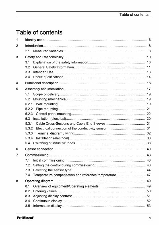
Table of contents1 Identity code........................................................................................................... 6
2 Introduction............................................................................................................. 82.1 Measured variables........................................................................................ 8
3 Safety and Responsibility..................................................................................... 103.1 Explanation of the safety information........................................................... 103.2 General Safety Information.......................................................................... 113.3 Intended Use................................................................................................ 133.4 Users' qualifications...................................................................................... 14
4 Functional description........................................................................................... 16
5 Assembly and installation..................................................................................... 175.1 Scope of delivery.......................................................................................... 195.2 Mounting (mechanical)................................................................................. 195.2.1 Wall mounting............................................................................................ 195.2.2 Pipe mounting........................................................................................... 215.2.3 Control panel mounting............................................................................. 225.3 Installation (electrical)................................................................................... 305.3.1 Cable Cross-Sections and Cable End Sleeves......................................... 315.3.2 Electrical connection of the conductivity sensor........................................ 315.3.3 Terminal diagram / wiring.......................................................................... 325.3.4 Installation (electrical)................................................................................ 385.4 Switching of inductive loads......................................................................... 38
6 Sensor connection................................................................................................ 40
7 Commissioning..................................................................................................... 437.1 Initial commissioning.................................................................................... 437.2 Setting the control during commissioning..................................................... 437.3 Selecting the sensor type ............................................................................ 447.4 Temperature compensation and reference temperature.............................. 47
8 Operating diagram................................................................................................ 498.1 Overview of equipment/Operating elements................................................ 498.2 Entering values............................................................................................. 508.3 Adjusting display contrast............................................................................. 518.4 Continuous display....................................................................................... 528.5 Information display....................................................................................... 53
Table of contents
3
8.6 Password...................................................................................................... 54
9 Operating menus ................................................................................................. 559.1 Calibrating [CAL] the conductivity sensor .................................................... 559.1.1 Calibration of the cell constant.................................................................. 579.1.2 Calibration of the temperature coefficient.................................................. 609.2 Setting limit values [LIMITS] ........................................................................ 639.3 Setting the control [CONTROL] ................................................................... 669.4 Setting inputs [INPUT] ................................................................................. 699.5 Setting outputs [OUTPUT] ........................................................................... 739.6 Setting the [DEVICE].................................................................................... 77
10 Control parameters and functions......................................................................... 7810.1 DULCOMETER® Compact Controller function states ............................... 7810.2 [STOP/START] key.................................................................................... 8010.3 Priming [PRIME]......................................................................................... 8110.4 Hysteresis limit value.................................................................................. 8210.5 Temperature correction variable................................................................ 8210.6 Checkout time for measured variable and correction variable................... 8410.7 Checkout time control................................................................................. 8410.8 Power relay "P-REL" as limit value relay.................................................... 8510.9 Setting and functional description of "Relay Used as a Solenoid Valve" . . 8610.10 Alarm relay............................................................................................... 8810.11 "Error logger" operating mode.................................................................. 88
11 Maintenance......................................................................................................... 8911.1 Error messages ......................................................................................... 8911.2 Changing the fuse, DULCOMETER® Compact Controller......................... 93
12 Technical data on DULCOMETER® Compact Controller...................................... 9412.1 Permissible ambient conditions.................................................................. 9412.2 Dimensions and weights............................................................................ 9412.3 Material data............................................................................................... 9512.4 Chemical Resistance.................................................................................. 9512.5 Sound Pressure Level................................................................................ 95
13 Electrical data....................................................................................................... 96
14 Spare parts and accessories.............................................................................. 101
Table of contents
4
15 Replacing spare part units ................................................................................. 10215.1 Replacing the top part of the housing....................................................... 10215.2 Replacing the lower part of the housing (wall/tube retaining bracket)...... 10415.3 Replacing the lower part of the housing (control panel installation)......... 106
16 Standards complied with and Declaration of Conformity.................................... 109
17 Disposal of Used Parts....................................................................................... 110
18 Glossary.............................................................................................................. 111
19 Index................................................................................................................... 112
Table of contents
5
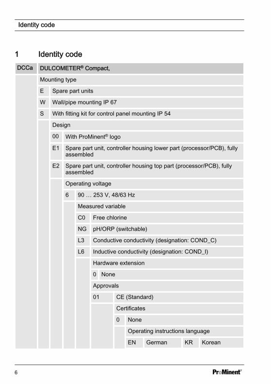
1 Identity codeDCCa DULCOMETER® Compact,
Mounting type
E Spare part units
W Wall/pipe mounting IP 67
S With fitting kit for control panel mounting IP 54
Design
00 With ProMinent® logo
E1 Spare part unit, controller housing lower part (processor/PCB), fullyassembled
E2 Spare part unit, controller housing top part (processor/PCB), fullyassembled
Operating voltage
6 90 … 253 V, 48/63 Hz
Measured variable
C0 Free chlorine
NG pH/ORP (switchable)
L3 Conductive conductivity (designation: COND_C)
L6 Inductive conductivity (designation: COND_I)
Hardware extension
0 None
Approvals
01 CE (Standard)
Certificates
0 None
Operating instructions language
EN German KR Korean
Identity code
6
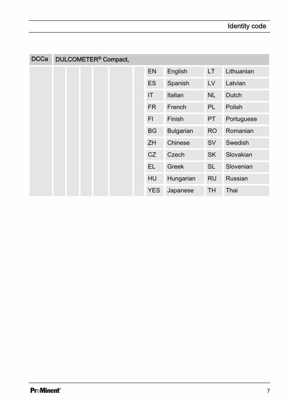
DCCa DULCOMETER® Compact,
EN English LT Lithuanian
ES Spanish LV Latvian
IT Italian NL Dutch
FR French PL Polish
FI Finish PT Portuguese
BG Bulgarian RO Romanian
ZH Chinese SV Swedish
CZ Czech SK Slovakian
EL Greek SL Slovenian
HU Hungarian RU Russian
YES Japanese TH Thai
Identity code
7
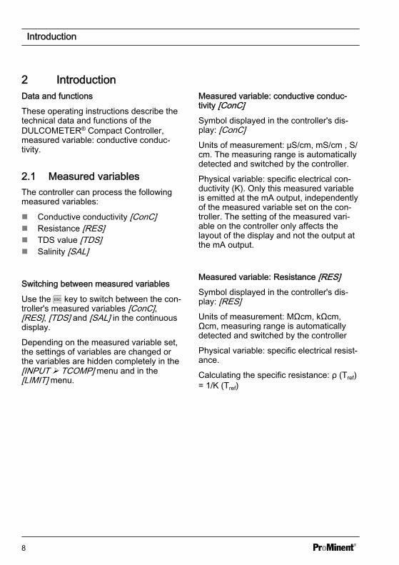
2 IntroductionData and functions
These operating instructions describe thetechnical data and functions of theDULCOMETER® Compact Controller,measured variable: conductive conduc‐tivity.
2.1 Measured variablesThe controller can process the followingmeasured variables:
n Conductive conductivity [ConC]n Resistance [RES]n TDS value [TDS]n Salinity [SAL]
Switching between measured variables
Use the key to switch between the con‐troller's measured variables [ConC],[RES], [TDS] and [SAL] in the continuousdisplay.
Depending on the measured variable set,the settings of variables are changed orthe variables are hidden completely in the[INPUT Ø TCOMP] menu and in the[LIMIT] menu.
Measured variable: conductive conduc‐tivity [ConC]Symbol displayed in the controller's dis‐play: [ConC]Units of measurement: μS/cm, mS/cm , S/cm. The measuring range is automaticallydetected and switched by the controller.
Physical variable: specific electrical con‐ductivity (K). Only this measured variableis emitted at the mA output, independentlyof the measured variable set on the con‐troller. The setting of the measured vari‐able on the controller only affects thelayout of the display and not the output atthe mA output.
Measured variable: Resistance [RES]Symbol displayed in the controller's dis‐play: [RES]Units of measurement: MΩcm, kΩcm,Ωcm, measuring range is automaticallydetected and switched by the controller
Physical variable: specific electrical resist‐ance.
Calculating the specific resistance: ρ (Tref)= 1/K (Tref)
Introduction
8
Measured variable: TDS value
Symbol displayed in the controller's dis‐play: [TDS] (total dissolved solids)
Unit of measurement: ppm (mg/l)
Physical variable: Total of all inorganicand organic substances dissolved in a sol‐vent
Display range: 0 …. 2000 ppm
Temperature range: 0 … 35 °C
[TLIMIT↑]: ≤ 40 °C
Setting the TDS value displayed: You canset a multiplicative factor [TDS] in the[INPUT] menu, with which the TDS valuedisplayed can be changed.
Displayed TDS value [ppm] = К (25 °C)[uS/cm] * TDS factor
Setting range of TDS factor: 0.400 …1.000 (Default: 0.640)
Temperature compensation is alwayslinear with the TDS display with a refer‐ence temperature of 25 °C .
Measured variable: Salinity (SAL)
Symbol displayed in the controller's dis‐play: [SAL] units: ‰ (g/kg)
Physical variable: Mass of salts in a kg ofwater given in PSU (practical salinityunits).
The salinity is derived from the conduc‐tivity measured, with a specified non-linear temperature compensation and areference conductivity (KCL).
Display range: 0 …. 70.0 ‰
Temperature range: 0 … 35 °C
[TLIMIT↑]: ≤ 35 °C
The salinity [SAL] is calculated based onthe[Practical Salinity Scale 1978 (PSS-78)]
Introduction
9
3 Safety and Responsibility3.1 Explanation of the safety
informationIntroduction
These operating instructions provide infor‐mation on the technical data and functionsof the product. These operating instruc‐tions provide detailed safety informationand are provided as clear step-by-stepinstructions.
The safety information and notes are cate‐gorised according to the followingscheme. A number of different symbolsare used to denote different situations.The symbols shown here serve only asexamples.
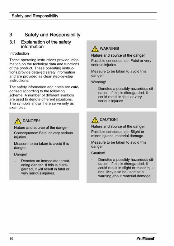
DANGER!
Nature and source of the dangerConsequence: Fatal or very seriousinjuries.
Measure to be taken to avoid thisdanger
Danger!
– Denotes an immediate threat‐ening danger. If this is disre‐garded, it will result in fatal orvery serious injuries.
WARNING!
Nature and source of the dangerPossible consequence: Fatal or veryserious injuries.
Measure to be taken to avoid thisdanger
Warning!
– Denotes a possibly hazardous sit‐uation. If this is disregarded, itcould result in fatal or veryserious injuries.
CAUTION!
Nature and source of the dangerPossible consequence: Slight orminor injuries, material damage.
Measure to be taken to avoid thisdanger
Caution!
– Denotes a possibly hazardous sit‐uation. If this is disregarded, itcould result in slight or minor inju‐ries. May also be used as awarning about material damage.
Safety and Responsibility
10

NOTICE!
Nature and source of the dangerDamage to the product or its sur‐roundings
Measure to be taken to avoid thisdanger
Note!
– Denotes a possibly damaging sit‐uation. If this is disregarded, theproduct or an object in its vicinitycould be damaged.
Type of informationHints on use and additional informa‐tionSource of the information, additionalmeasuresInformation!– Denotes hints on use and other
useful information. It does notindicate a hazardous or dam‐aging situation.
3.2 General Safety Information
WARNING!
Live parts!Possible consequence: Fatal or veryserious injuries
– Measure: Disconnect the mainspower supply prior to opening thehousing
– De-energise damaged, defectiveor manipulated units by discon‐necting the mains plug
WARNING!
Unauthorised access!Possible consequence: Fatal or veryserious injuries
– Measure: Ensure that there canbe no unauthorised access to theunit
Safety and Responsibility
11
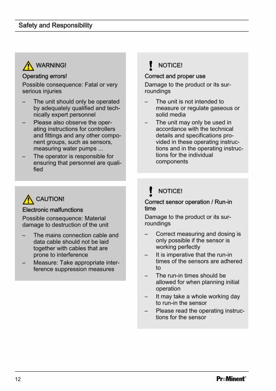
WARNING!
Operating errors!Possible consequence: Fatal or veryserious injuries
– The unit should only be operatedby adequately qualified and tech‐nically expert personnel
– Please also observe the oper‐ating instructions for controllersand fittings and any other compo‐nent groups, such as sensors,measuring water pumps ...
– The operator is responsible forensuring that personnel are quali‐fied
CAUTION!
Electronic malfunctionsPossible consequence: Materialdamage to destruction of the unit
– The mains connection cable anddata cable should not be laidtogether with cables that areprone to interference
– Measure: Take appropriate inter‐ference suppression measures
NOTICE!
Correct and proper useDamage to the product or its sur‐roundings
– The unit is not intended tomeasure or regulate gaseous orsolid media
– The unit may only be used inaccordance with the technicaldetails and specifications pro‐vided in these operating instruc‐tions and in the operating instruc‐tions for the individualcomponents
NOTICE!
Correct sensor operation / Run-intimeDamage to the product or its sur‐roundings
– Correct measuring and dosing isonly possible if the sensor isworking perfectly
– It is imperative that the run-intimes of the sensors are adheredto
– The run-in times should beallowed for when planning initialoperation
– It may take a whole working dayto run-in the sensor
– Please read the operating instruc‐tions for the sensor
Safety and Responsibility
12
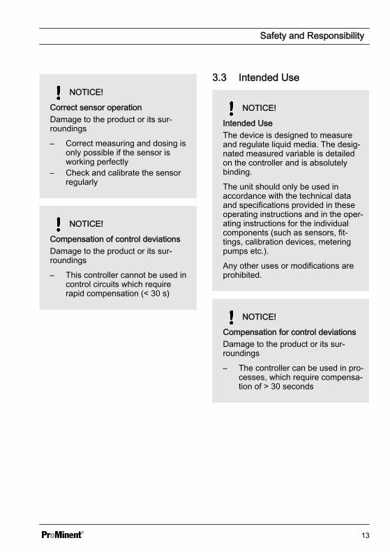
NOTICE!
Correct sensor operationDamage to the product or its sur‐roundings
– Correct measuring and dosing isonly possible if the sensor isworking perfectly
– Check and calibrate the sensorregularly
NOTICE!
Compensation of control deviationsDamage to the product or its sur‐roundings
– This controller cannot be used incontrol circuits which requirerapid compensation (< 30 s)
3.3 Intended Use
NOTICE!
Intended UseThe device is designed to measureand regulate liquid media. The desig‐nated measured variable is detailedon the controller and is absolutelybinding.
The unit should only be used inaccordance with the technical dataand specifications provided in theseoperating instructions and in the oper‐ating instructions for the individualcomponents (such as sensors, fit‐tings, calibration devices, meteringpumps etc.).
Any other uses or modifications areprohibited.
NOTICE!
Compensation for control deviationsDamage to the product or its sur‐roundings
– The controller can be used in pro‐cesses, which require compensa‐tion of > 30 seconds
Safety and Responsibility
13
3.4 Users' qualifications
WARNING!
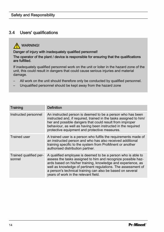
Danger of injury with inadequately qualified personnel!The operator of the plant / device is responsible for ensuring that the qualificationsare fulfilled.
If inadequately qualified personnel work on the unit or loiter in the hazard zone of theunit, this could result in dangers that could cause serious injuries and materialdamage.
– All work on the unit should therefore only be conducted by qualified personnel.– Unqualified personnel should be kept away from the hazard zone
Training Definition
Instructed personnel An instructed person is deemed to be a person who has beeninstructed and, if required, trained in the tasks assigned to him/her and possible dangers that could result from improperbehaviour, as well as having been instructed in the requiredprotective equipment and protective measures.
Trained user A trained user is a person who fulfils the requirements made ofan instructed person and who has also received additionaltraining specific to the system from ProMinent or anotherauthorised distribution partner.
Trained qualified per‐sonnel
A qualified employee is deemed to be a person who is able toassess the tasks assigned to him and recognize possible haz‐ards based on his/her training, knowledge and experience, aswell as knowledge of pertinent regulations. The assessment ofa person's technical training can also be based on severalyears of work in the relevant field.
Safety and Responsibility
14
Training Definition
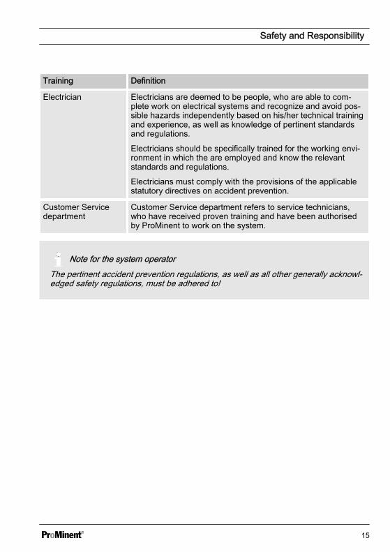
Electrician Electricians are deemed to be people, who are able to com‐plete work on electrical systems and recognize and avoid pos‐sible hazards independently based on his/her technical trainingand experience, as well as knowledge of pertinent standardsand regulations.
Electricians should be specifically trained for the working envi‐ronment in which the are employed and know the relevantstandards and regulations.
Electricians must comply with the provisions of the applicablestatutory directives on accident prevention.
Customer Servicedepartment
Customer Service department refers to service technicians,who have received proven training and have been authorisedby ProMinent to work on the system.
Note for the system operatorThe pertinent accident prevention regulations, as well as all other generally acknowl‐edged safety regulations, must be adhered to!
Safety and Responsibility
15
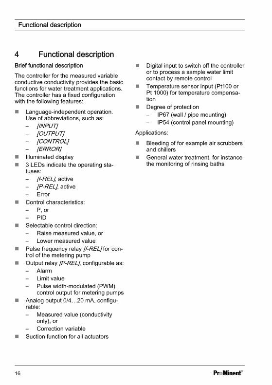
4 Functional descriptionBrief functional description
The controller for the measured variableconductive conductivity provides the basicfunctions for water treatment applications.The controller has a fixed configurationwith the following features:
n Language-independent operation.Use of abbreviations, such as:– [INPUT]– [OUTPUT]– [CONTROL]– [ERROR]
n Illuminated displayn 3 LEDs indicate the operating sta‐
tuses:– [f-REL], active– [P-REL], active– Error
n Control characteristics:– P, or– PID
n Selectable control direction:– Raise measured value, or– Lower measured value
n Pulse frequency relay [f-REL] for con‐trol of the metering pump
n Output relay [P-REL], configurable as:– Alarm– Limit value– Pulse width-modulated (PWM)
control output for metering pumpsn Analog output 0/4…20 mA, configu‐
rable:– Measured value (conductivity
only), or– Correction variable
n Suction function for all actuators
n Digital input to switch off the controlleror to process a sample water limitcontact by remote control
n Temperature sensor input (Pt100 orPt 1000) for temperature compensa‐tion
n Degree of protection– IP67 (wall / pipe mounting)– IP54 (control panel mounting)
Applications:
n Bleeding of for example air scrubbersand chillers
n General water treatment, for instancethe monitoring of rinsing baths
Functional description
16
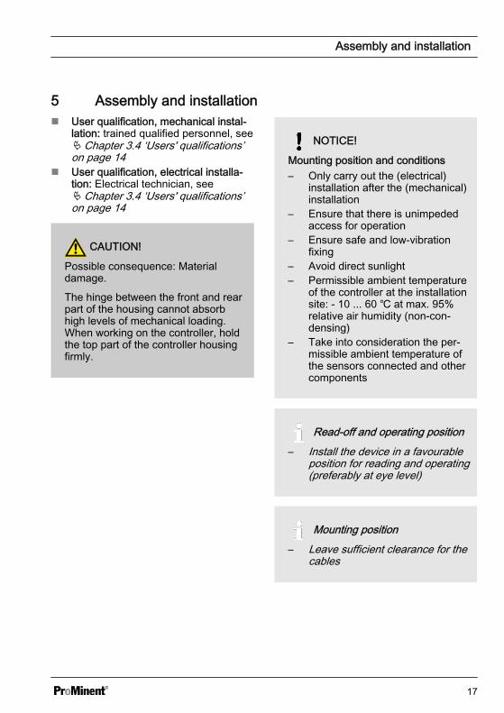
5 Assembly and installationn User qualification, mechanical instal‐
lation: trained qualified personnel, seeÄ Chapter 3.4 ‘Users' qualifications’on page 14
n User qualification, electrical installa‐tion: Electrical technician, seeÄ Chapter 3.4 ‘Users' qualifications’on page 14
CAUTION!
Possible consequence: Materialdamage.
The hinge between the front and rearpart of the housing cannot absorbhigh levels of mechanical loading.When working on the controller, holdthe top part of the controller housingfirmly.
NOTICE!
Mounting position and conditions– Only carry out the (electrical)
installation after the (mechanical)installation
– Ensure that there is unimpededaccess for operation
– Ensure safe and low-vibrationfixing
– Avoid direct sunlight– Permissible ambient temperature
of the controller at the installationsite: - 10 ... 60 at max. 95%relative air humidity (non-con‐densing)
– Take into consideration the per‐missible ambient temperature ofthe sensors connected and othercomponents
Read-off and operating position– Install the device in a favourable
position for reading and operating(preferably at eye level)
Mounting position– Leave sufficient clearance for the
cables
Assembly and installation
17

Packaging materialDispose of packaging material in anenvironmentally responsible way. Allpackaging components carry the cor‐responding recycling code .
Assembly and installation
18
5.1 Scope of deliveryThe following parts belong to the standard scope of delivery of a DULCOMETER® Com‐pact Controller.
Description Quantity
Assembled device 1
Cable connection set DMTa/DXMa (metr.) 1
Operating instructions 1
5.2 Mounting (mechanical)The DULCOMETER® Compact Controller is suitable for mounting on a wall, pipe or con‐trol panel.
Mounting materials (contained in the scope of supply):
Description Quantity
Wall/tube retaining bracket 1
Round head screws 5x45 mm 2
Washer 5.3 2
Rawlplug Ø 8 mm, plastic 2
5.2.1 Wall mountingMounting (mechanical)
Assembly and installation
19
2
1
A0273
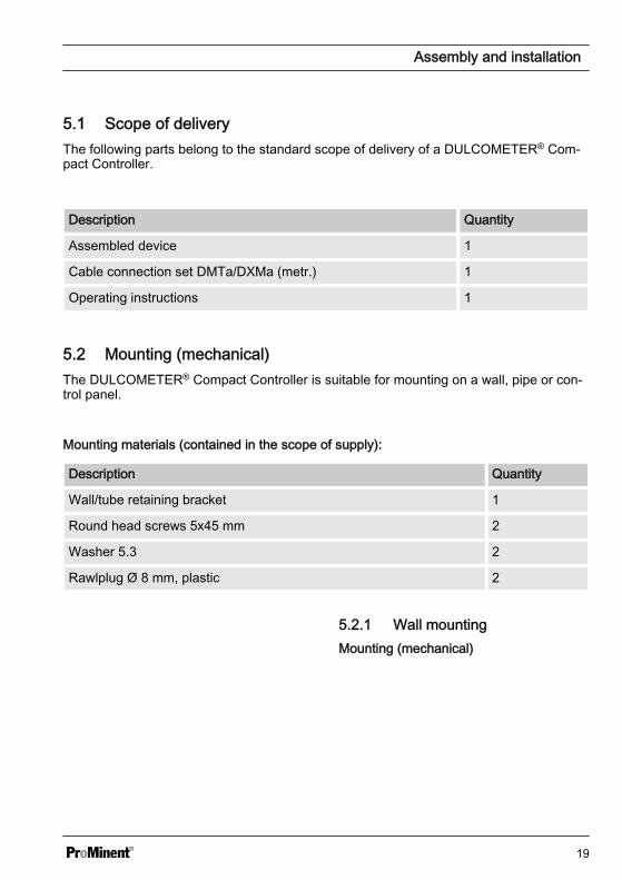
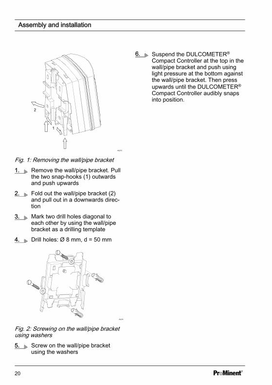
Fig. 1: Removing the wall/pipe bracket1. Remove the wall/pipe bracket. Pull
the two snap-hooks (1) outwardsand push upwards
2. Fold out the wall/pipe bracket (2)and pull out in a downwards direc‐tion
3. Mark two drill holes diagonal toeach other by using the wall/pipebracket as a drilling template
4. Drill holes: Ø 8 mm, d = 50 mm
A0274
Fig. 2: Screwing on the wall/pipe bracketusing washers5. Screw on the wall/pipe bracket
using the washers
6. Suspend the DULCOMETER®
Compact Controller at the top in thewall/pipe bracket and push usinglight pressure at the bottom againstthe wall/pipe bracket. Then pressupwards until the DULCOMETER®
Compact Controller audibly snapsinto position.
Assembly and installation
20
5.2.2 Pipe mountingMounting (mechanical)
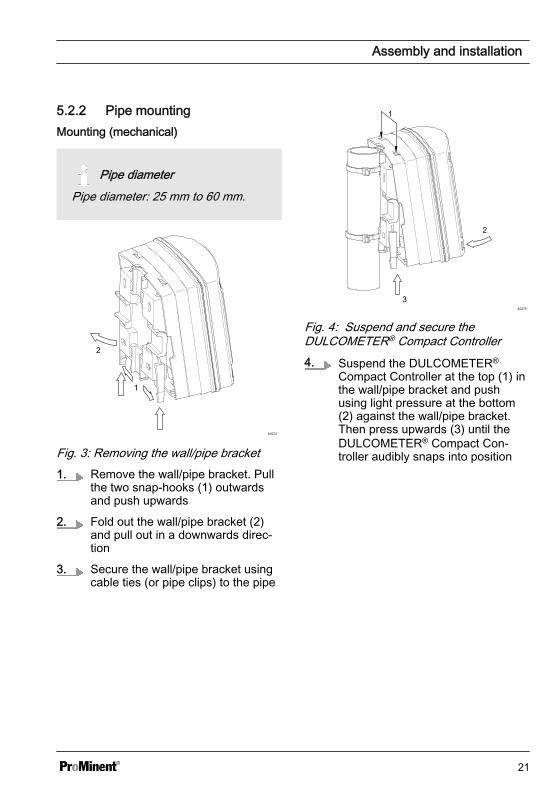
Pipe diameterPipe diameter: 25 mm to 60 mm.
2
1
A0273
Fig. 3: Removing the wall/pipe bracket1. Remove the wall/pipe bracket. Pull
the two snap-hooks (1) outwardsand push upwards
2. Fold out the wall/pipe bracket (2)and pull out in a downwards direc‐tion
3. Secure the wall/pipe bracket usingcable ties (or pipe clips) to the pipe
A0275
3
2
1
Fig. 4: Suspend and secure theDULCOMETER® Compact Controller4. Suspend the DULCOMETER®
Compact Controller at the top (1) inthe wall/pipe bracket and pushusing light pressure at the bottom(2) against the wall/pipe bracket.Then press upwards (3) until theDULCOMETER® Compact Con‐troller audibly snaps into position
Assembly and installation
21
5.2.3 Control panel mountingMounting kit for control panel installation of the DULCOMETER® Compact Controller:Order number 1037273
Description Quantity
Drilling template sheet 3872-4 1
PT screw (3.5 x 22) 3
Profile seals 2
Strain relief strip DF3/DF4 1
PT screw (3.5 x 10) 2
Individual parts packed in transparent cover / Mounting kit is not contained in thestandard scope of supply
CAUTION!
Material thickness of control panelPossible consequence: material damage
– The thickness of the material of the control panel should be at least 2 mm toensure secure fixing
In the mounted state, the DULCOMETER® Compact Controller extends approx. 30mm from the control panel.
Assembly and installation
22
Preparing the control panel
I.
A0347
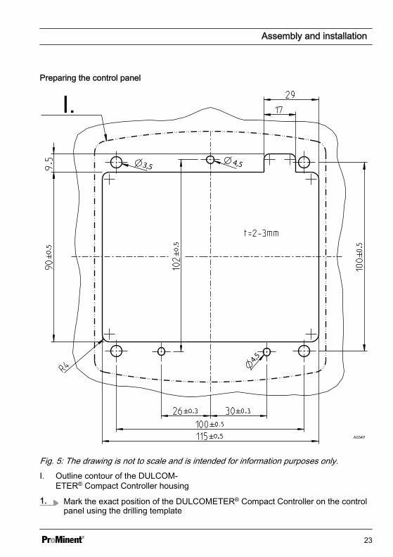
Fig. 5: The drawing is not to scale and is intended for information purposes only.I. Outline contour of the DULCOM‐
ETER® Compact Controller housing
1. Mark the exact position of the DULCOMETER® Compact Controller on the controlpanel using the drilling template
Assembly and installation
23
2.
Core holeAdhere to the 3.5 mm Ø as the core hole diameter for screwing in the fixingbolts.
Drill four holes for the bolts for the top section of the controller housing using a 3.5mm Ø drill bit
3. Drill three holes for the bolts for the bottom section of the controller housing usinga 4.5 mm Ø drill bit
4. Drill four holes using an 8 mm Ø drill bit and use a jigsaw to cut the cut-out
ð Deburr all the edges.
Assembly and installation
24
Fitting the DULCOMETER® CompactController into the cut-out in the controlpanel
NOTICE!
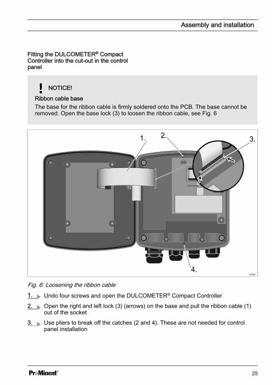
Ribbon cable baseThe base for the ribbon cable is firmly soldered onto the PCB. The base cannot beremoved. Open the base lock (3) to loosen the ribbon cable, see Fig. 6
1. 2. 3.
4.
Fig. 6: Loosening the ribbon cable1. Undo four screws and open the DULCOMETER® Compact Controller
2. Open the right and left lock (3) (arrows) on the base and pull the ribbon cable (1)out of the socket
3. Use pliers to break off the catches (2 and 4). These are not needed for controlpanel installation
Assembly and installation
25
1.2.
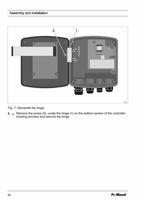
Fig. 7: Dismantle the hinge4. Remove the screw (2), unclip the hinge (1) on the bottom section of the controller
housing (arrows) and remove the hinge
Assembly and installation
26
A03601.
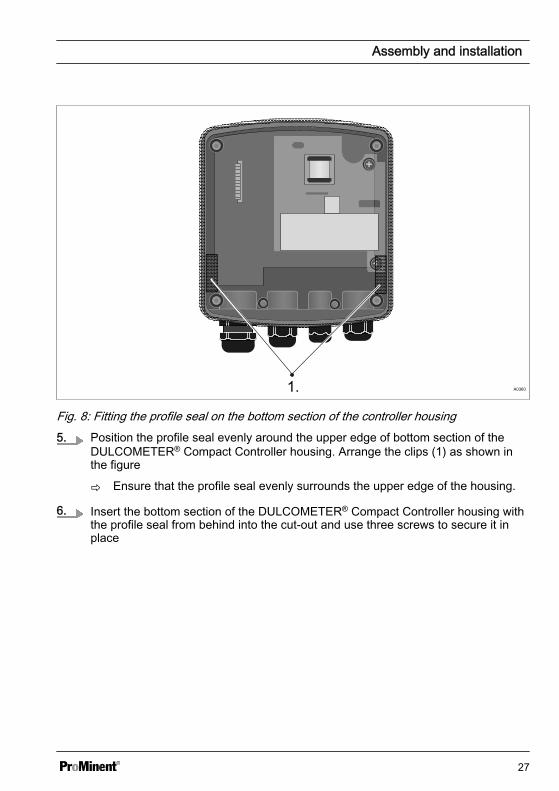
Fig. 8: Fitting the profile seal on the bottom section of the controller housing5. Position the profile seal evenly around the upper edge of bottom section of the
DULCOMETER® Compact Controller housing. Arrange the clips (1) as shown inthe figure
ð Ensure that the profile seal evenly surrounds the upper edge of the housing.
6. Insert the bottom section of the DULCOMETER® Compact Controller housing withthe profile seal from behind into the cut-out and use three screws to secure it inplace
Assembly and installation
27
A0351
1.
2.1.
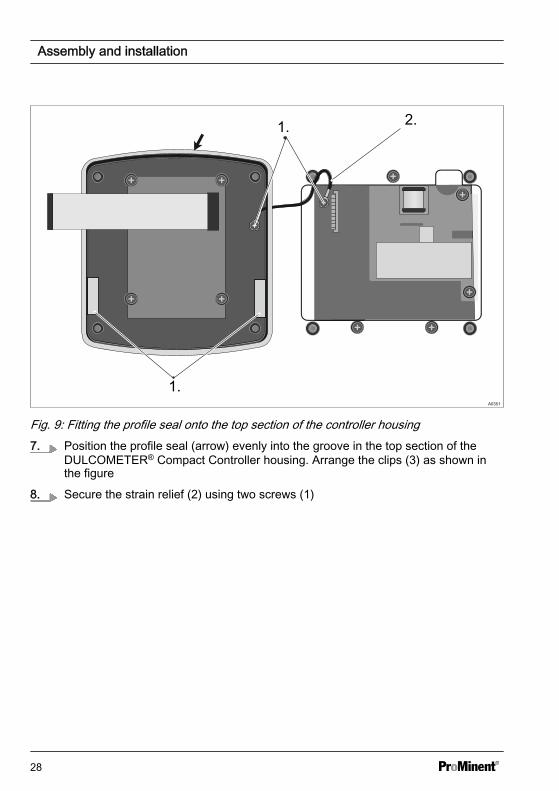
Fig. 9: Fitting the profile seal onto the top section of the controller housing7. Position the profile seal (arrow) evenly into the groove in the top section of the
DULCOMETER® Compact Controller housing. Arrange the clips (3) as shown inthe figure
8. Secure the strain relief (2) using two screws (1)
Assembly and installation
28
A0352
1.
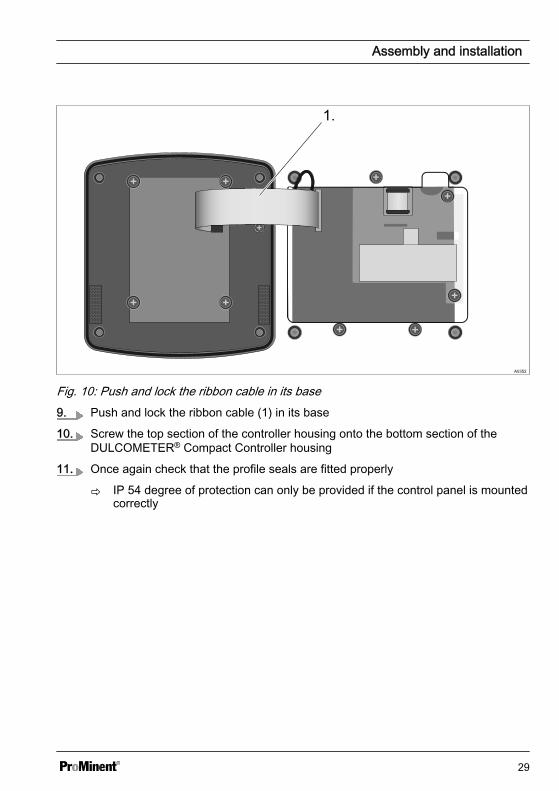
Fig. 10: Push and lock the ribbon cable in its base9. Push and lock the ribbon cable (1) in its base
10. Screw the top section of the controller housing onto the bottom section of theDULCOMETER® Compact Controller housing
11. Once again check that the profile seals are fitted properly
ð IP 54 degree of protection can only be provided if the control panel is mountedcorrectly
Assembly and installation
29
5.3 Installation (electrical)
WARNING!
Live parts!Possible consequence: Fatal or veryserious injuries
– Measure: Disconnect the elec‐trical power supply to the unitbefore opening the housing andsecure to prevent unintentionalreconnection
– Disconnect damaged or defectivedevices or devices that havebeen tampered with and preventunintended reconnection
– The plant operator is responsiblefor providing an appropriate iso‐lating device, such as an emer‐gency-off switch etc.
Do not route the controller's signalleads alongside interference-pronecabling. This could lead to controllermalfunctions.
Assembly and installation
30
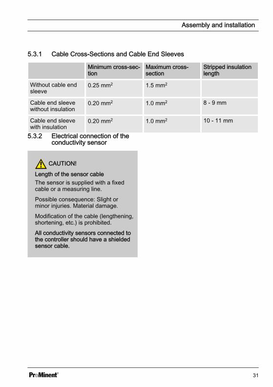
5.3.1 Cable Cross-Sections and Cable End Sleeves
Minimum cross-sec‐tion
Maximum cross-section
Stripped insulationlength
Without cable endsleeve
0.25 mm2 1.5 mm2
Cable end sleevewithout insulation
0.20 mm2 1.0 mm2 8 - 9 mm
Cable end sleevewith insulation
0.20 mm2 1.0 mm2 10 - 11 mm
5.3.2 Electrical connection of theconductivity sensor
CAUTION!
Length of the sensor cableThe sensor is supplied with a fixedcable or a measuring line.
Possible consequence: Slight orminor injuries. Material damage.
Modification of the cable (lengthening,shortening, etc.) is prohibited.
All conductivity sensors connected tothe controller should have a shieldedsensor cable.
Assembly and installation
31
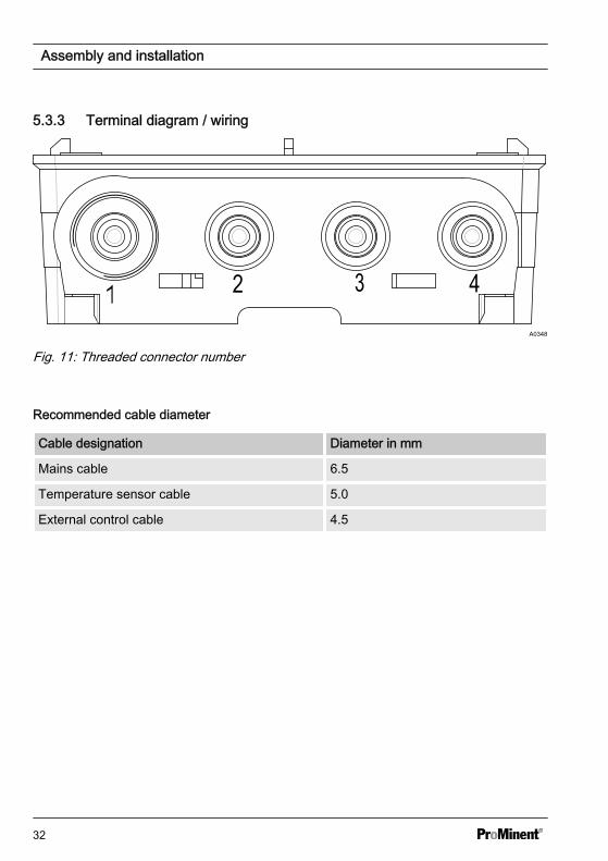
5.3.3 Terminal diagram / wiring
A0348
Fig. 11: Threaded connector number
Recommended cable diameter
Cable designation Diameter in mm
Mains cable 6.5
Temperature sensor cable 5.0
External control cable 4.5
Assembly and installation
32
Sensor
Red Blac
k
Blue
Yello
w/G
reen
Brow
nMains voltage
A1612
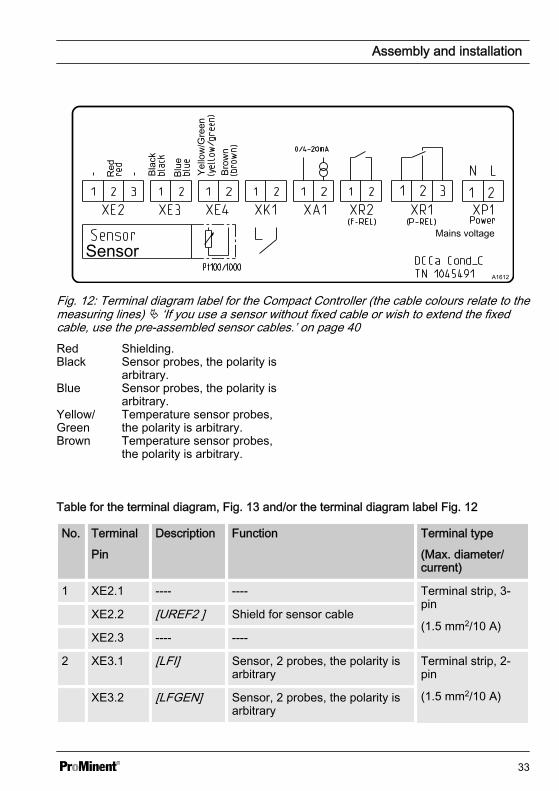
Fig. 12: Terminal diagram label for the Compact Controller (the cable colours relate to themeasuring lines) Ä ‘If you use a sensor without fixed cable or wish to extend the fixedcable, use the pre-assembled sensor cables.’ on page 40Red Shielding.Black Sensor probes, the polarity is
arbitrary.Blue Sensor probes, the polarity is
arbitrary.Yellow/Green
Temperature sensor probes,the polarity is arbitrary.
Brown Temperature sensor probes,the polarity is arbitrary.
Table for the terminal diagram, Fig. 13 and/or the terminal diagram label Fig. 12
No. Terminal
Pin
Description Function Terminal type
(Max. diameter/current)
1 XE2.1 ---- ---- Terminal strip, 3-pin
(1.5 mm2/10 A) XE2.2 [UREF2 ] Shield for sensor cable
XE2.3 ---- ----
2 XE3.1 [LFI] Sensor, 2 probes, the polarity isarbitrary
Terminal strip, 2-pin
(1.5 mm2/10 A) XE3.2 [LFGEN] Sensor, 2 probes, the polarity isarbitrary
Assembly and installation
33
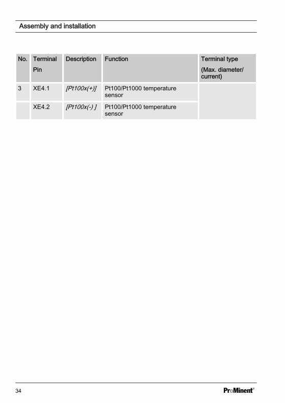
No. Terminal
Pin
Description Function Terminal type
(Max. diameter/current)
3 XE4.1 [Pt100x(+)] Pt100/Pt1000 temperaturesensor
XE4.2 [Pt100x(-) ] Pt100/Pt1000 temperaturesensor
Assembly and installation
34
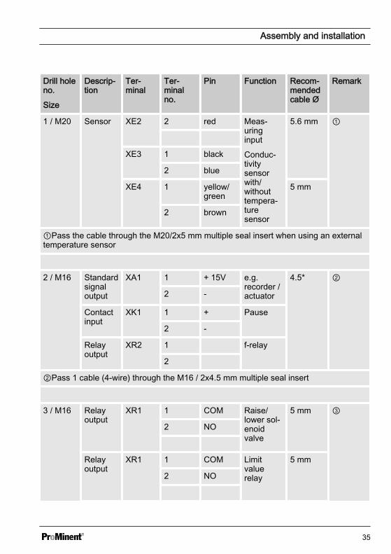
Drill holeno.
Size
Descrip‐tion
Ter‐minal
Ter‐minalno.
Pin Function Recom‐mendedcable Ø
Remark
1 / M20 Sensor XE2 2 red Meas‐uringinput
Conduc‐tivitysensorwith/withouttempera‐turesensor
5.6 mm ①
XE3 1 black
2 blue
XE4 1 yellow/green
5 mm
2 brown
①Pass the cable through the M20/2x5 mm multiple seal insert when using an externaltemperature sensor
2 / M16 Standardsignaloutput
XA1 1 + 15V e.g.recorder /actuator
4.5* ②
2 -
Contactinput
XK1 1 + Pause
2 -
Relayoutput
XR2 1 f-relay
2
②Pass 1 cable (4-wire) through the M16 / 2x4.5 mm multiple seal insert
3 / M16 Relayoutput
XR1 1 COM Raise/lower sol‐enoidvalve
5 mm ③
2 NO
Relayoutput
XR1 1 COM Limitvaluerelay
5 mm
2 NO
Assembly and installation
35
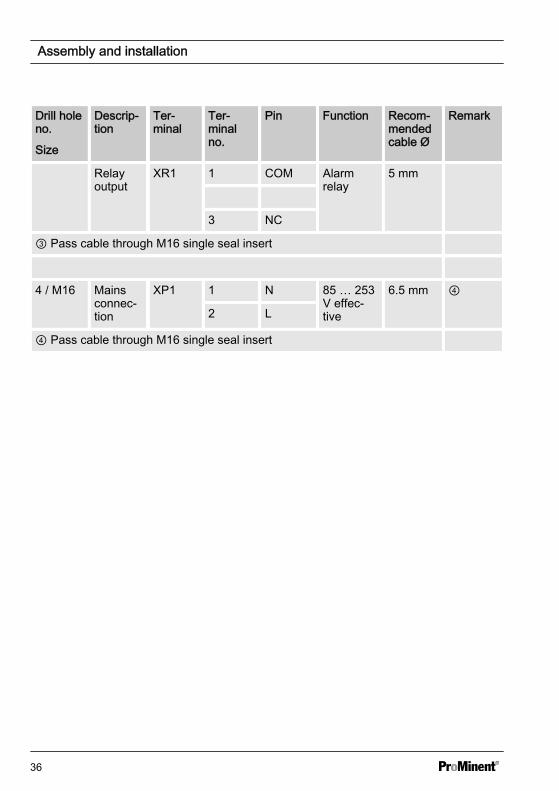
Drill holeno.
Size
Descrip‐tion
Ter‐minal
Ter‐minalno.
Pin Function Recom‐mendedcable Ø
Remark
Relayoutput
XR1 1 COM Alarmrelay
5 mm
3 NC
③ Pass cable through M16 single seal insert
4 / M16 Mainsconnec‐tion
XP1 1 N 85 … 253V effec‐tive
6.5 mm ④
2 L
④ Pass cable through M16 single seal insert
Assembly and installation
36
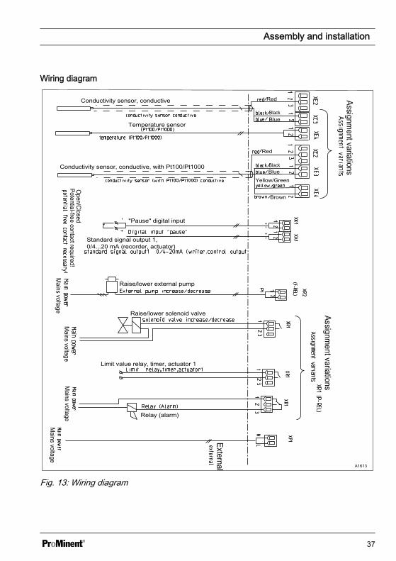
Wiring diagram
Assignment variations
Assignment variations
External
Open/ClosedPotential-free contact required!
Mains voltage
Mains voltage
Mains voltage
Mains voltage
Conductivity sensor, conductive
Temperature sensor
Conductivity sensor, conductive, with Pt100/Pt1000
"Pause" digital input
Standard signal output 1, 0/4...20 mA (recorder, actuator)
Raise/lower external pump
Raise/lower solenoid valve
Limit value relay, timer, actuator 1
Relay (alarm)
Red
Red
Blue
BlackBlue
Black
Yellow/Green
Brown
A1613
Fig. 13: Wiring diagram
Assembly and installation
37
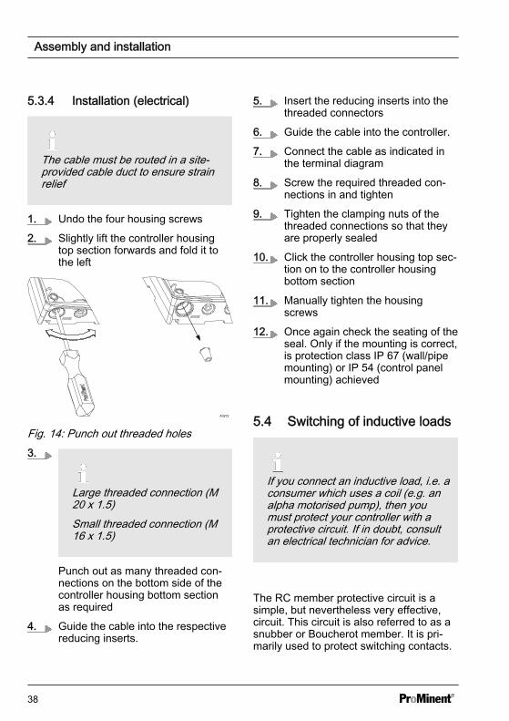
5.3.4 Installation (electrical)
The cable must be routed in a site-provided cable duct to ensure strainrelief
1. Undo the four housing screws
2. Slightly lift the controller housingtop section forwards and fold it tothe left
A0272
Fig. 14: Punch out threaded holes3.
Large threaded connection (M20 x 1.5)Small threaded connection (M16 x 1.5)
Punch out as many threaded con‐nections on the bottom side of thecontroller housing bottom sectionas required
4. Guide the cable into the respectivereducing inserts.
5. Insert the reducing inserts into thethreaded connectors
6. Guide the cable into the controller.
7. Connect the cable as indicated inthe terminal diagram
8. Screw the required threaded con‐nections in and tighten
9. Tighten the clamping nuts of thethreaded connections so that theyare properly sealed
10. Click the controller housing top sec‐tion on to the controller housingbottom section
11. Manually tighten the housingscrews
12. Once again check the seating of theseal. Only if the mounting is correct,is protection class IP 67 (wall/pipemounting) or IP 54 (control panelmounting) achieved
5.4 Switching of inductive loads
If you connect an inductive load, i.e. aconsumer which uses a coil (e.g. analpha motorised pump), then youmust protect your controller with aprotective circuit. If in doubt, consultan electrical technician for advice.
The RC member protective circuit is asimple, but nevertheless very effective,circuit. This circuit is also referred to as asnubber or Boucherot member. It is pri‐marily used to protect switching contacts.
Assembly and installation
38
When switching off, the connection inseries of a resistor and capacitor meansthat the current can be dissipated in adamped oscillation.
Also when switching on, the resistor actsas a current limiter for the capacitorcharging process. The RC member pro‐tective circuit is highly suitable for ACvoltage supplies.
The magnitude of the resistance R ofthe RC member is determined accordingto the following equation:
R=U/IL(Where U= Voltage across the load andIL = current through the load)
The magnitude of the capacitor is deter‐mined using the following equation:
C=k * ILk=0,1...2 (dependent on the application).
Only use capacitors of class X2.
Units: R = Ohm; U = Volt; IL = Ampere;C = µF
If consumers are connected whichhave a high starting current (e.g. plug-in, switched mains power supplies),then a means of limiting the startingcurrent must be provided.
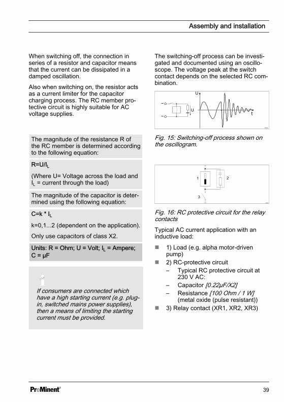
The switching-off process can be investi‐gated and documented using an oscillo‐scope. The voltage peak at the switchcontact depends on the selected RC com‐bination.
A0842
Fig. 15: Switching-off process shown onthe oscillogram.
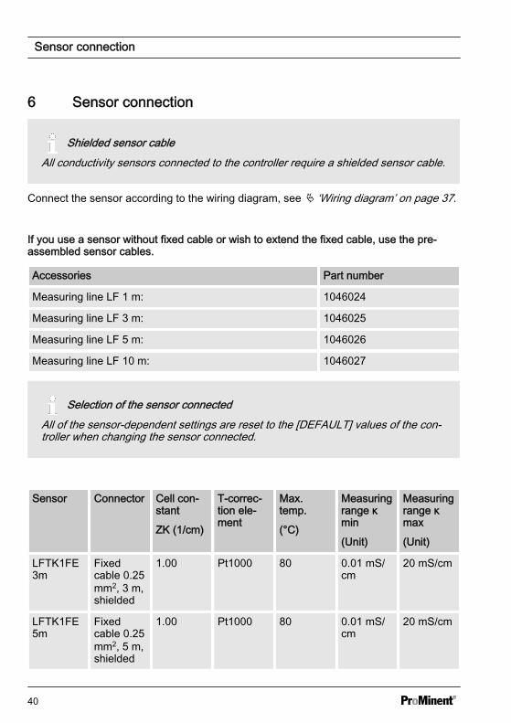
A0835
Fig. 16: RC protective circuit for the relaycontactsTypical AC current application with aninductive load:
n 1) Load (e.g. alpha motor-drivenpump)
n 2) RC-protective circuit– Typical RC protective circuit at
230 V AC:– Capacitor [0.22µF/X2]– Resistance [100 Ohm / 1 W]
(metal oxide (pulse resistant))n 3) Relay contact (XR1, XR2, XR3)
Assembly and installation
39
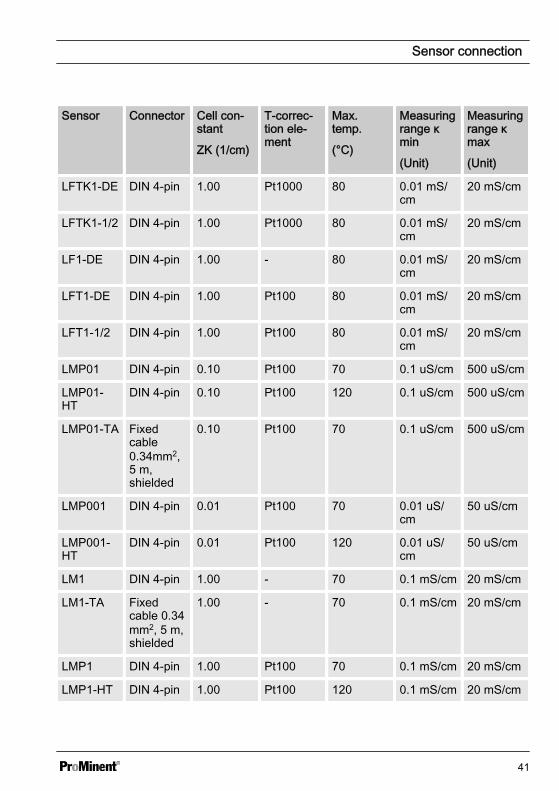
6 Sensor connection
Shielded sensor cableAll conductivity sensors connected to the controller require a shielded sensor cable.
Connect the sensor according to the wiring diagram, see Ä ‘Wiring diagram’ on page 37.
If you use a sensor without fixed cable or wish to extend the fixed cable, use the pre-assembled sensor cables.
Accessories Part number
Measuring line LF 1 m: 1046024
Measuring line LF 3 m: 1046025
Measuring line LF 5 m: 1046026
Measuring line LF 10 m: 1046027
Selection of the sensor connectedAll of the sensor-dependent settings are reset to the [DEFAULT] values of the con‐troller when changing the sensor connected.
Sensor Connector Cell con‐stant
ZK (1/cm)
T-correc‐tion ele‐ment
Max.temp.
(°C)
Measuringrange κmin
(Unit)
Measuringrange κmax
(Unit)
LFTK1FE3m
Fixedcable 0.25mm2, 3 m,shielded
1.00 Pt1000 80 0.01 mS/cm
20 mS/cm
LFTK1FE5m
Fixedcable 0.25mm2, 5 m,shielded
1.00 Pt1000 80 0.01 mS/cm
20 mS/cm
Sensor connection
40
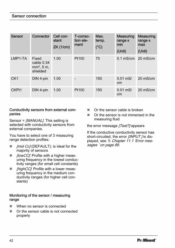
Sensor Connector Cell con‐stant
ZK (1/cm)
T-correc‐tion ele‐ment
Max.temp.
(°C)
Measuringrange κmin
(Unit)
Measuringrange κmax
(Unit)
LFTK1-DE DIN 4-pin 1.00 Pt1000 80 0.01 mS/cm
20 mS/cm
LFTK1-1/2 DIN 4-pin 1.00 Pt1000 80 0.01 mS/cm
20 mS/cm
LF1-DE DIN 4-pin 1.00 - 80 0.01 mS/cm
20 mS/cm
LFT1-DE DIN 4-pin 1.00 Pt100 80 0.01 mS/cm
20 mS/cm
LFT1-1/2 DIN 4-pin 1.00 Pt100 80 0.01 mS/cm
20 mS/cm
LMP01 DIN 4-pin 0.10 Pt100 70 0.1 uS/cm 500 uS/cm
LMP01-HT
DIN 4-pin 0.10 Pt100 120 0.1 uS/cm 500 uS/cm
LMP01-TA Fixedcable0.34mm2,5 m,shielded
0.10 Pt100 70 0.1 uS/cm 500 uS/cm
LMP001 DIN 4-pin 0.01 Pt100 70 0.01 uS/cm
50 uS/cm
LMP001-HT
DIN 4-pin 0.01 Pt100 120 0.01 uS/cm
50 uS/cm
LM1 DIN 4-pin 1.00 - 70 0.1 mS/cm 20 mS/cm
LM1-TA Fixedcable 0.34mm2, 5 m,shielded
1.00 - 70 0.1 mS/cm 20 mS/cm
LMP1 DIN 4-pin 1.00 Pt100 70 0.1 mS/cm 20 mS/cm
LMP1-HT DIN 4-pin 1.00 Pt100 120 0.1 mS/cm 20 mS/cm
Sensor connection
41
Sensor Connector Cell con‐stant
ZK (1/cm)
T-correc‐tion ele‐ment
Max.temp.
(°C)
Measuringrange κmin
(Unit)
Measuringrange κmax
(Unit)
LMP1-TA Fixedcable 0.34mm2, 5 m,shielded
1.00 Pt100 70 0.1 mS/cm 20 mS/cm
CK1 DIN 4-pin 1.00 - 150 0.01 mS/cm
20 mS/cm
CKPt1 DIN 4-pin 1.00 Pt100 150 0.01 mS/cm
20 mS/cm
Conductivity sensors from external com‐panies
Sensor = [MANUAL]. This setting isselected with conductivity sensors fromexternal companies.
You have to select one of 3 measuringrange detection profiles:
n [mid Cc] (DEFAULT): is ideal for themajority of sensors
n [lowCC]: Profile with a higher meas‐uring frequency in the lowest conduc‐tivity ranges (for small cell constants)
n [highCC]: Profile with a lower meas‐uring frequency in the medium con‐ductivity ranges (for higher cell con‐stants)
Monitoring of the sensor / measuringrange
n When no sensor is connectedn Or the sensor cable is not connected
properly
n Or the sensor cable is brokenn Or the sensor is not immersed in the
measuring fluid
the error message [Test?] appears
If the conductive conductivity sensor hasshort-circuited, the error [INPUT ] is dis‐played, see Ä Chapter 11.1 ‘Error mes‐sages ’ on page 89.
Sensor connection
42
7 Commissioningn User qualification: trained user, see
Ä Chapter 3.4 ‘Users' qualifications’on page 14
WARNING!
Sensor run-in periodsThis can result in hazardous incorrectmetering
– Correct measuring and meteringis only possible if the sensor isworking perfectly
– Observe the sensor's operatinginstructions
– Calibrate the sensor after com‐missioning
Following mechanical and electrical instal‐lation, integrated the controller into themeasuring point.
7.1 Initial commissioningThe controller is in STOP state when thecontroller is first switched on.
Setting the auto-ranging profile
1. Select the conductive conductivitysensor used.
2. Enter the actual sensor cablelength.
ð Subsequently the control set‐ting and the setting of the dif‐ferent parameters dependenton the process to be measured.
3. When connecting external sensors,[INPUT > SENSOR > MANUAL],adjust the auto-ranging profile, seeÄ ‘Using external sensors’on page 46
7.2 Setting the control duringcommissioning
NOTICE!
Reset to factory settingsWhen switching over the meteringdirection, all actuators in the controllerare reset to the factory settings for theselected metering direction.
For safety reasons, all the actuatorsare deactivated. The basic load isreset to 0 %. All parameters relatingto the actuator, are reset to the fac‐tory setting.
Reset all the parameters that relate tothe actuator.
Commissioning
43
The controller only controls ‘one-way’ .Only one position or one negative controlvariable can be calculated. The directionof the control variable is set in the ‘PUMP’menu. There is no dead zone. In thissense, the control cannot be ‘deactivated’(except with ‘STOP’ or ‘PAUSE’ ).The value of the P-proportion of the con‐trol (Xp) is specified for the controller inthe unit of the corresponding measuredvariable.
With pure P-control and a differencebetween the set and actual values, whichcorresponds to the Xp value, the calcu‐lated control variable is +100% (at the‘raise’ setting) and -100% (at the ‘lower’setting).
7.3 Selecting the sensor type
Input of the cable length and thecross-sectional areaThe precise entry of the cable lengthis important with longer cable lengths.With a conductivity value of e.g.10mS (corresponding to 100 ohms),the displayed value changes by 1%every 10 m of cable length.The Pt100 measurement is correctedby the cable resistance that comesfrom the cable length entered. Thecorrection for a cable with a cross-sectional area of 0.25 mm 2 is 3.5 °Cevery 10 m of cable length.ProMinent sensor cable, seeÄ Table on page 101and the fixed-cable sensors are 0.25 mm2.Adjustable parameters in the [INPUT]> [CABLE] menu– 0.14 mm2
– 0.25mm2 (default value)– 0.34 mm2
– 0.50 mm2
Commissioning
44
Use of fixed-cable ProMinent sensors
1. Press and move the cursor withthe or keys at the [INPUT]menu item and confirm the selec‐tion with .
2. Move the cursor with the or keys at the [SENSOR] menu itemand confirm with .
3. Select the sensor used using the or keys and confirm with .
Enter the cable length used:
Adjusting the fixed cable lengthIf you are using a conductivity sensorwith a fixed cable and have to shortenthe length of the cable, adjust theactual cable length in the menu under[LEN].
4. Use the or keys to select themenu item [LEN] and confirm with
.
5. Adjust the entry for the cable lengthusing the , or keys and con‐firm with .
6. Press twice to return to the con‐tinuous display.
Using ProMinent sensors with 4-pin plug
1. Press and move the cursor withthe or keys at the [INPUT]menu item and confirm the selec‐tion with .
2. Move the cursor with the or keys at the [SENSOR] menu itemand confirm with .
3. Select the sensor used using the or keys and confirm with .
Enter the cable length used:
4. Use the or keys to select themenu item [LEN] and confirm with
.
5. Adjust the entry for the cable lengthused using the , or keysand confirm with .
6. Press twice to return to the con‐tinuous display.
Commissioning
45
Using external sensors
1. Press and move the cursor withthe or keys at the [INPUT]menu item and confirm the selec‐tion with .
2. Move the cursor with the or keys at the [SENSOR] menu itemand confirm with .
3. Move the cursor with the or keys at the [MANUAL] menu itemand confirm with .
ð The question[ARE YOU SURE]appears
4. If you wish to set the [SENSOR]entry to [MANUAL], select [YES]using the or keys and confirmwith .
Enter the cable length used:
5. Use the or keys to select themenu item [LEN] and confirm with
.
Selecting the auto-ranging profile
6. Use the or keys to select themenu item [PROFILE] and confirmwith .
7. Adjust the [PROFILE] entry usingthe or keys and confirm with
.
n If the cell constant is < 1, thenuse [lowCC]
n If the cell constant is > 1, thenuse [highCC]
n If the cell constant = 1, thenuse [midCC]
If the selected [PROFILE] entrydoes not deliver the requiredresult, then try another profile.
8. Press twice to return to the con‐tinuous display.
Commissioning
46
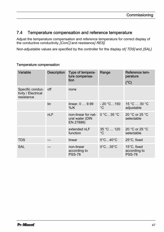
7.4 Temperature compensation and reference temperatureAdjust the temperature compensation and reference temperature for correct display ofthe conductive conductivity [ConC] and resistance[ RES].Non-adjustable values are specified by the controller for the display of[ TDS] and [SAL].
Temperature compensation
Variable Description Type of tempera‐ture compensa‐tion
Range Reference tem‐perature
(°C)
Specific conduc‐tivity / Electricalresistance
off none
lin linear, 0 … 9.99%/K
- 20 °C…150°C
15 °C … 30 °Cadjustable
nLF non-linear for nat‐ural water (DINEN 27888)
0 °C…35 °C 20 °C or 25 °Cselectable
extended nLFfunction
35 °C … 120°C
20 °C or 25 °Cselectable
TDS --- linear 0°C…40°C 25°C, fixed
SAL --- non-linearaccording toPSS-78
0°C…35°C 15°C, fixedaccording toPSS-78
Commissioning
47
The conductive conductivity measured atthe fluid temperature is converted to thereference temperature [TREF].
Changing the reference tem‐peratureIf the reference temperature [TREF] ischanged, the temperature coefficient[TCOEFF] has to be recalibrated, seeÄ Chapter 9.1.2 ‘Calibration of thetemperature coefficient’ on page 60
Adjustable process for temperature com‐pensation
n [off]– Temperature compensation is
switched off. It is measuredbased on the set reference tem‐perature.
n [lin]– Linear temperature compensa‐
tion, see Ä Chapter 10.5 ‘Tem‐perature correction variable’on page 82, for the temperaturerange permitted for the sensors.The reference temperature[TREF] can be set between 15 °Cand 30 °C.
n [nLF]– Non-linear temperature compen‐
sation according to DIN EN27888 for natural water, between0 °C ... 35 °C. The reference tem‐perature [TREF] can be switched,20 °C / 25 °C.
Commissioning
48
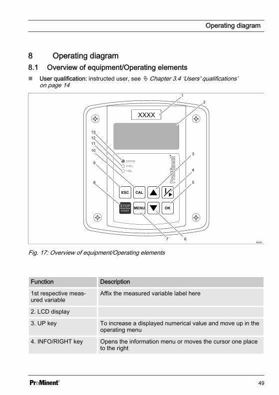
8 Operating diagram8.1 Overview of equipment/Operating elementsn User qualification: instructed user, see Ä Chapter 3.4 ‘Users' qualifications’
on page 14
A0291
Fig. 17: Overview of equipment/Operating elements
Function Description
1st respective meas‐ured variable
Affix the measured variable label here
2. LCD display
3. UP key To increase a displayed numerical value and move up in theoperating menu
4. INFO/RIGHT key Opens the information menu or moves the cursor one placeto the right
Operating diagram
49
Function Description
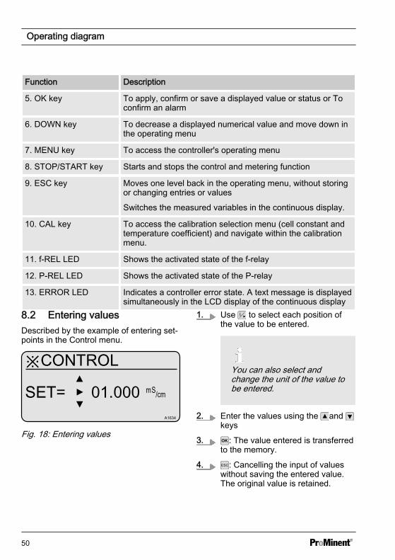
5. OK key To apply, confirm or save a displayed value or status or Toconfirm an alarm
6. DOWN key To decrease a displayed numerical value and move down inthe operating menu
7. MENU key To access the controller's operating menu
8. STOP/START key Starts and stops the control and metering function
9. ESC key Moves one level back in the operating menu, without storingor changing entries or values
Switches the measured variables in the continuous display.
10. CAL key To access the calibration selection menu (cell constant andtemperature coefficient) and navigate within the calibrationmenu.
11. f-REL LED Shows the activated state of the f-relay
12. P-REL LED Shows the activated state of the P-relay
13. ERROR LED Indicates a controller error state. A text message is displayedsimultaneously in the LCD display of the continuous display
8.2 Entering valuesDescribed by the example of entering set‐points in the Control menu.
※CONTROL
SET= 01.000A1634
Fig. 18: Entering values
1. Use to select each position ofthe value to be entered.
You can also select andchange the unit of the value tobe entered.
2. Enter the values using the and keys
3. : The value entered is transferredto the memory.
4. : Cancelling the input of valueswithout saving the entered value.The original value is retained.
Operating diagram
50
8.3 Adjusting display contrastIf the DULCOMETER® Compact Controlleris set to ‘continuous display’ , you can setthe contrast of the LCD-display. Bypressing the key you can adjust theLCD display contrast so it is darker. Bypressing the key you can adjust theLCD display contrast so it is lighter. Hereeach key press represents a contrastlevel. I.e. the key must be pressed oncefor each contrast level.
Operating diagram
51
8.4 Continuous display
A1614
1
2
345
6
7 ConC µS/cm
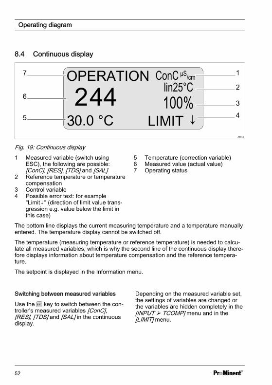
Fig. 19: Continuous display1 Measured variable (switch using
ESC), the following are possible:[ConC], [RES], [TDS] and [SAL]
2 Reference temperature or temperaturecompensation
3 Control variable4 Possible error text: for example
"Limit↓" (direction of limit value trans‐gression e.g. value below the limit inthis case)
5 Temperature (correction variable)6 Measured value (actual value)7 Operating status
The bottom line displays the current measuring temperature and a temperature manuallyentered. The temperature display cannot be switched off.
The temperature (measuring temperature or reference temperature) is needed to calcu‐late all measured variables, which is why the second line of the continuous display there‐fore displays information about temperature compensation and the reference tempera‐ture.
The setpoint is displayed in the Information menu.
Switching between measured variables
Use the key to switch between the con‐troller's measured variables [ConC],[RES], [TDS] and [SAL] in the continuousdisplay.
Depending on the measured variable set,the settings of variables are changed orthe variables are hidden completely in the[INPUT Ø TCOMP] menu and in the[LIMIT] menu.
Operating diagram
52
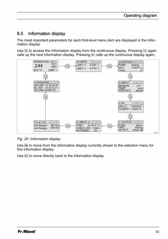
8.5 Information displayThe most important parameters for each first-level menu item are displayed in the Infor‐mation display.
Use to access the Information display from the continuous display. Pressing againcalls up the next Information display. Pressing calls up the continuous display again.
A1615
LIMITSLIMIT↑= 0.020LIMIT↓= 0.010
SENSOR: LF1TEMP: auto
CABLE LEN: 3.00mP-REL: alarmmA OUT: meas val
CONTROLPUMP: dosing ↓
TYPE: PSET= 1.000mS/cm
INPUT
CONTACT: pause
OUTPUT
f-REL: dosing
INPUT_2LAST ERR.
VERSIONSSW-VER 01.00.00.00
SN 2366733289 (07)
mA Range↑ 88 minmA Range ↓ 136 min
BL-VER 03.02.02.01
TREF: lin 25.0 °C
CELLC: 1.0000cm-1
TCOEFF= 1.90%/°C
CAL
AUTORNG: 33
Fig. 20: Information displayUse to move from the information display currently shown to the selection menu forthis information display.
Use to move directly back to the information display.
Operating diagram
53
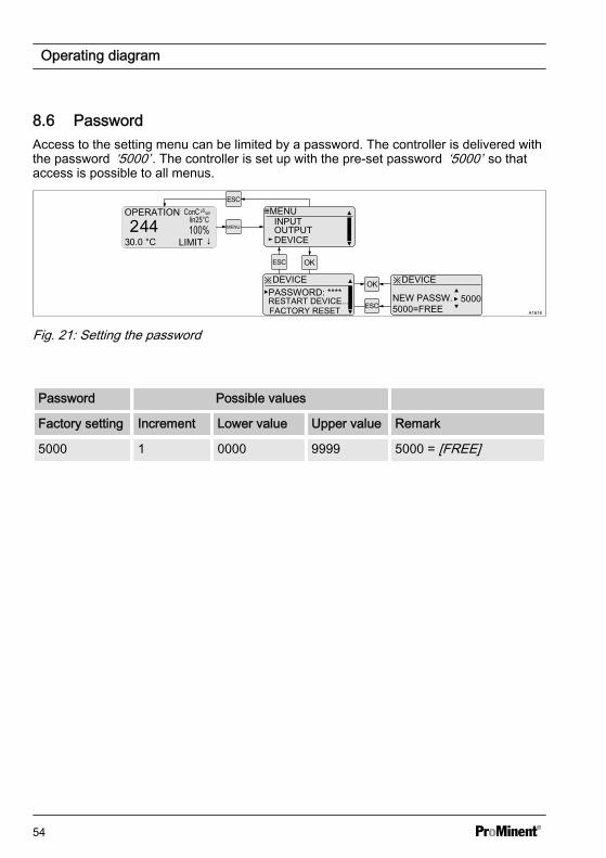
8.6 PasswordAccess to the setting menu can be limited by a password. The controller is delivered withthe password ‘5000’ . The controller is set up with the pre-set password ‘5000’ so thataccess is possible to all menus.
A1616
MENU
≡MENU
DEVICEOUTPUTINPUT
※DEVICEPASSWORD: ****
※DEVICE
NEW PASSW. 5000=FREE
RESTART DEVICE... 5000FACTORY RESET
Fig. 21: Setting the password
Password Possible values
Factory setting Increment Lower value Upper value Remark
5000 1 0000 9999 5000 = [FREE]
Operating diagram
54
9 Operating menusn User qualification: instructed user, see Ä Chapter 3.4 ‘Users' qualifications’
on page 14
A1617
CELLCONST ℂ CAL STOP
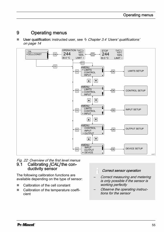
Fig. 22: Overview of the first level menus9.1 Calibrating [CAL] the con‐
ductivity sensorThe following calibration functions areavailable depending on the type of sensor:
n Calibration of the cell constantn Calibration of the temperature coeffi‐
cient
Correct sensor operation– Correct measuring and metering
is only possible if the sensor isworking perfectly
– Observe the operating instruc‐tions for the sensor
Operating menus
55
Incorrect calibrationAn error message ‘ERR’ appears ifthe result of the calibration lies out‐side the specified tolerance limits. Inthis case the current calibration is notapplied.Check the prerequisites for calibrationand clear the error. Then repeat cali‐brationIn the event of repeated calibrationfailure, observe the notes given in thesensor operating instructions.
During calibration, the controller sets thecontrol outputs to ‘0’ . Exception: If a basicload or a manual control variable hasbeen set. This remains active. The mAstandard signal output is frozen.
When calibration has been completedsuccessfully, all of the error checksrelating to the measured value arerestarted. The controller saves the datadetermined for the cell constant and tem‐perature coefficient when the calibration issuccessful.
The conductivity sensors can be cali‐brated using 3 different methods. The cellconstant is adjusted directly or indirectly inall methods:
n Calibration compared to a referencesolution
n Calibration compared to a referencemeasurement (e.g. manual measuringdevice)
n Calibration by entering a preciselyknown or determined cell constant
Operating menus
56
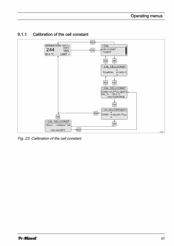
9.1.1 Calibration of the cell constant
A1625
CALCELLCONST
CAL CELLCONST
TCoeffCAL 1.90%/°C
COND= 43,2µS/cm @25°C
CAL=CONTINUE
TCOEFF
CAL CELLCONST
CAL_T= 155.0 °C
COND=
CAL CELLCONST@25°C
043,975 µS/cm
CELLCCAL CELLCONST
1.0000cm-1 OK
CAL=ACCEPT
Fig. 23: Calibration of the cell constant
Operating menus
57
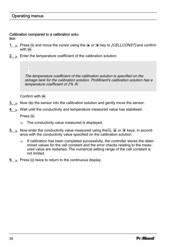
Calibration compared to a calibration solu‐tion
1. Press and move the cursor using the or key to [CELLCONST] and confirmwith .
2. Enter the temperature coefficient of the calibration solution.
The temperature coefficient of the calibration solution is specified on thestorage tank for the calibration solution. ProMinent's calibration solution has atemperature coefficient of 2% /K.
Confirm with .
3. Now dip the sensor into the calibration solution and gently move the sensor.
4. Wait until the conductivity and temperature measured value has stabilised.
Press .
ð The conductivity value measured is displayed.
5. Now enter the conductivity value measured using the , or keys, in accord‐ance with the conductivity value specified on the calibration solution.
ð If calibration has been completed successfully, the controller stores the deter‐mined values for the cell constant and the error checks relating to the meas‐ured value are restarted. The numerical setting range of the cell constant isnot limited.
6. Press twice to return to the continuous display.
Operating menus
58
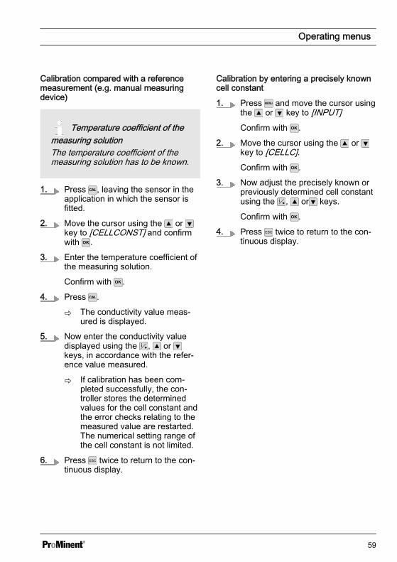
Calibration compared with a referencemeasurement (e.g. manual measuringdevice)
Temperature coefficient of themeasuring solutionThe temperature coefficient of themeasuring solution has to be known.
1. Press , leaving the sensor in theapplication in which the sensor isfitted.
2. Move the cursor using the or key to [CELLCONST] and confirmwith .
3. Enter the temperature coefficient ofthe measuring solution.
Confirm with .
4. Press .
ð The conductivity value meas‐ured is displayed.
5. Now enter the conductivity valuedisplayed using the , or keys, in accordance with the refer‐ence value measured.
ð If calibration has been com‐pleted successfully, the con‐troller stores the determinedvalues for the cell constant andthe error checks relating to themeasured value are restarted.The numerical setting range ofthe cell constant is not limited.
6. Press twice to return to the con‐tinuous display.
Calibration by entering a precisely knowncell constant
1. Press and move the cursor usingthe or key to [INPUT]Confirm with .
2. Move the cursor using the or key to [CELLC].Confirm with .
3. Now adjust the precisely known orpreviously determined cell constantusing the , or keys.
Confirm with .
4. Press twice to return to the con‐tinuous display.
Operating menus
59
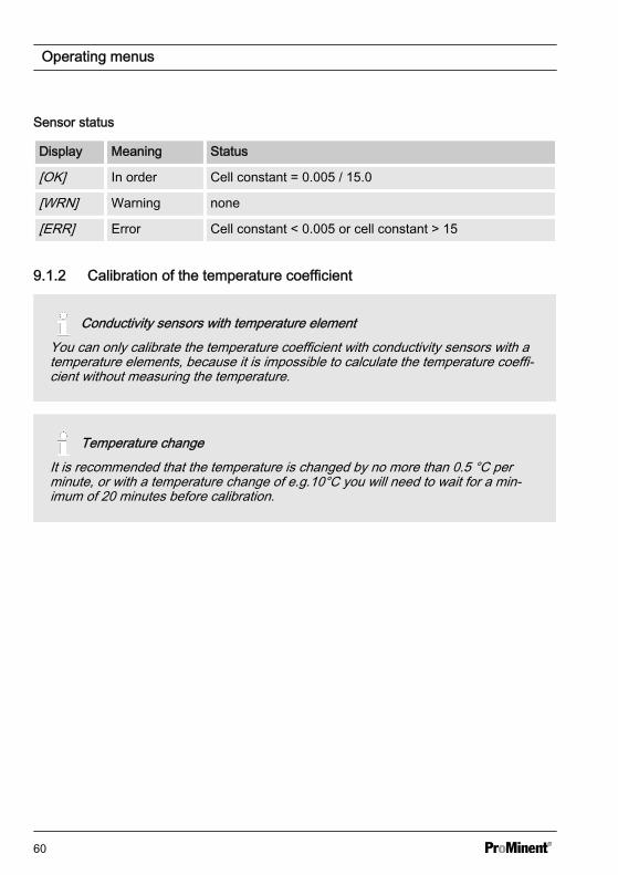
Sensor status
Display Meaning Status
[OK] In order Cell constant = 0.005 / 15.0
[WRN] Warning none
[ERR] Error Cell constant < 0.005 or cell constant > 15
9.1.2 Calibration of the temperature coefficient
Conductivity sensors with temperature elementYou can only calibrate the temperature coefficient with conductivity sensors with atemperature elements, because it is impossible to calculate the temperature coeffi‐cient without measuring the temperature.
Temperature changeIt is recommended that the temperature is changed by no more than 0.5 °C perminute, or with a temperature change of e.g.10°C you will need to wait for a min‐imum of 20 minutes before calibration.
Operating menus
60
A1626
CALCELLCONST
CAL TEMPCOEFF
CAL_T1= 22.0 °C
CHANGE TEMP
TCOEFF
CAL TEMPCOEFF
T2 > 32.0 °C or
CAL_T2= 43.0 °C
CAL TEMPCOEFF
TCOEFF=0.00%/°CCAL TEMPCOEFF
CAL=OLD
CAL=CONTINUE
T2 < 12.0 °C
CAL=CONTINUE
WAITCAL TEMPCOEFF
T2 > 32.0 °C orT2 < 12.0 °C
I.
II.STABLE ?
CAL_T2= 43.0 °C
CAL TEMPCOEFF
CAL=CONTINUE
ACCEPT ?
III.
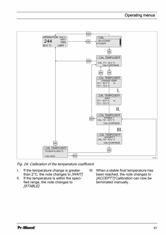
Fig. 24: Calibration of the temperature coefficientI. If the temperature change is greater
than 2°C, the note changes to [WAIT]II. If the temperature is within the speci‐
fied range, the note changes to[STABLE]
III. When a stable final temperature hasbeen reached, the note changes to[ACCEPT?] Calibration can now beterminated manually.
Operating menus
61
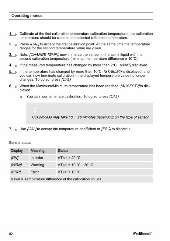
1. Calibrate at the first calibration temperature calibration temperature; this calibrationtemperature should be close to the selected reference temperature.
2. Press [CAL] to accept the first calibration point. At the same time the temperatureranges for the second temperature value are given.
3. Note: [CHANGE TEMP], now immerse the sensor in the same liquid with thesecond calibration temperature (minimum temperature difference ± 10°C)
4. If the measured temperature has changed by more than 2°C , [WAIT] displayed.
5. If the temperature has changed by more than 10°C, [STABLE?] is displayed, andyou can now terminate calibration if the displayed temperature value no longerchanges. To do so, press [CAL].
6. When the Maximum/Minimum temperature has been reached, [ACCEPT?] is dis‐played
ð You can now terminate calibration. To do so, press [CAL].
This process may take 10 ... 20 minutes depending on the type of sensor.
7. Use [CAL] to accept the temperature coefficient or [ESC] to discard it
Sensor status
Display Meaning Status
[OK] In order ΔTkal > 20 °C
[WRN] Warning ΔTkal = 10 °C…20 °C
[ERR] Error ΔTkal < 10 °C
ΔTkal = Temperature difference of the calibration liquids
Operating menus
62
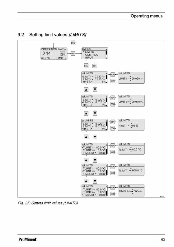
9.2 Setting limit values [LIMITS]
A1620
MENU
≡MENULIMITSCONTROLINPUT
※LIMITS
LIMIT↓= 0.010LIMIT↑= 0.020
HYST.= 5%
※LIMITS
00.020
※LIMITS
LIMIT↑=
00.010
※LIMITS
LIMIT↓= 0.010 LIMIT↑= 0.020
※LIMITS
05 %
※LIMITSLIMIT↓= 0.020 LIMIT↑= 0.010
※LIMITS
TLIMIT↓= 0.0 °CTLIMIT↑= 80.0 °C
TIMELIM.= 0min
※LIMITS
HYST. =
80.0 °C
※LIMITS
TLIMIT↓= 0.0 °CTLIMIT↑= 80.0 °C
TIMELIM.= 0min
※LIMITS
TIMELIM.= 000min
LIMIT↓=
※LIMITS
TLIMIT↓= 0.0 °CTLIMIT↑= 80.0 °C
TIMELIM.= 0min
※LIMITS
000.0 °CTLIMIT↓=
HYST.= 5%
HYST.= 5%
TLIMIT↑=
Fig. 25: Setting limit values (LIMITS)
Operating menus
63
Setting Possible values
Display Startingvalue
Increment Lower value Upper value Remark
[LIMIT ↑] 0.02 S/cm 0.001 0.000 uS/cm
2.000 S/cm upper limit value
[LIMIT ↓] 0.01 mS/cm
0.001 0.000 uS/cm
2.000 S/cm lower limit value
[HYST. ] 5% 1% 1% 20% hysteresis of limitvalues
[TLIMIT ↑]°C
30.0 °C 0.1 °C 0.0 °C 150.0 °C upper limit cor‐rection value °C
[TLIMIT ↓]°C
10.0 °C 0.1 °C 0.0 °C 150.0 °C lower limit cor‐rection value °C
[TLIMIT ↑]°F
86.0 °F 0.1 °F 32.0 °F 302.0 °F upper limit cor‐rection value °F
[TLIMIT ↓]°F
32.0 °F 0.1 °F 32.0 °F 302.0 °F lower limit cor‐rection value °F
[TIMELIM.] 0 min =OFF
1 min 0 999 Checktime aftera limit value hasbeen exceededor undershot
If [TDS] or [SAL] is set in the continuousdisplay, the setting values for [TLIMIT↑]and [TLIMIT↓] are hidden in the [LIMIT]menu:
n [TLIMIT↓] can be changed if the con‐tinuous display is showing [Cond_C]or [RES].
n [TLIMIT↑] is fixed at 40 °C (with TDS)and 35 °C (with SAL). If the value setat [Cond_C] for [TLIMIT↑] is less thanthis value, this setting is retained.
Hysteresis: the hysteresis is specified as a%, as an absolute indication is impossibledue to the breadth of the measuringrange. The indication refers to the valuesgiven under [LIMIT↑] and [LIMIT↓].
Hysteresis = [HYST.]If the value has fallen below a limit value,then the limit value criteria are reset whenthe measured value has reached thevalue of the limit value plus hysteresis.
Operating menus
64
If the value has fallen below a limit value,then the limit value criteria are reset whenthe measured value has reached thevalue of the limit value minus hysteresis.
If the limit value criteria no longer exist onexpiry of [TIMELIM] , then the control isautomatically reactivated.
Operating menus
65
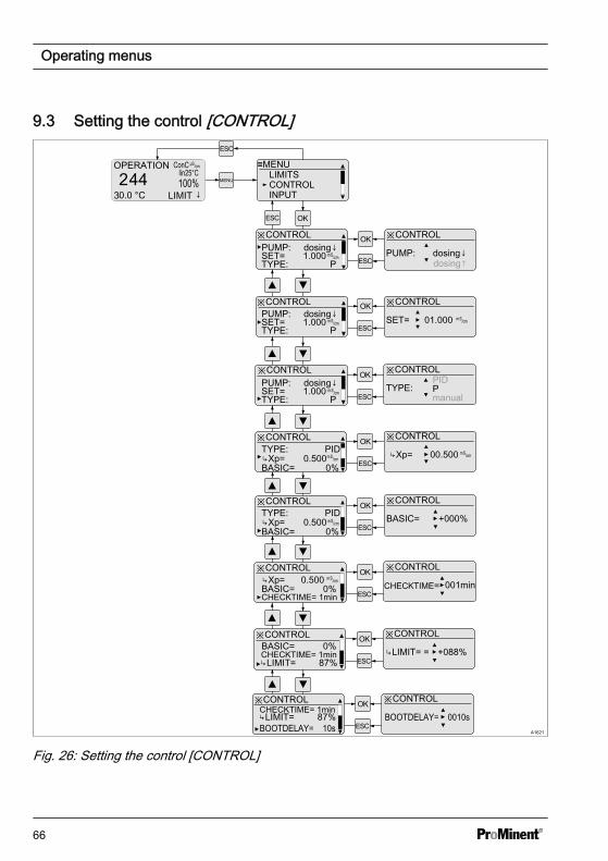
9.3 Setting the control [CONTROL]
A1621
MENU
≡MENULIMITSCONTROLINPUT
※CONTROLPUMP: dosing↓SET= 1.000 TYPE: P
※CONTROL
PUMP: dosing↓
※CONTROL
SET= 01.000
※CONTROL
※CONTROL
TYPE: P
※CONTROL
※CONTROL ※CONTROL
00.500
※CONTROL ※CONTROL
BASIC= +000%
PUMP: dosing↓SET= 1.000TYPE: P
PUMP: dosing↓SET= 1.000TYPE: P
TYPE: PIDXp= 0.500BASIC= 0%
Xp=
TYPE: PIDXp= 0.500BASIC= 0%
※CONTROL ※CONTROL
CHECKTIME= 001minCHECKTIME= 1min
Xp= 0.500BASIC= 0%
※CONTROL ※CONTROL
LIMIT= = +088%CHECKTIME= 1minLIMIT= 87%
BASIC= 0%
dosing↑
PID
manual
※CONTROL ※CONTROLCHECKTIME= 1minLIMIT= 87%BOOTDELAY= 10s
BOOTDELAY= 0010s
Fig. 26: Setting the control [CONTROL]
Operating menus
66
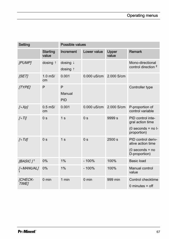
Setting Possible values
Startingvalue
Increment Lower value Uppervalue
Remark
[PUMP] dosing ↑ dosing ↓
dosing ↑
Mono-directionalcontrol direction 2
[SET] 1.0 mS/cm
0.001 0.000 uS/cm 2.000 S/cm
[TYPE] P P
Manual
PID
Controller type
[Xp] 0.5 mS/cm
0.001 0.000 uS/cm 2.000 S/cm P-proportion ofcontrol variable
[Ti] 0 s 1 s 0 s 9999 s PID control inte‐gral action time
(0 seconds = no I-proportion)
[Td] 0 s 1 s 0 s 2500 s PID control deriv‐ative action time
(0 seconds = noD-proportion)
[BASIC ] 1 0% 1% - 100% 100% Basic load
[MANUAL]1
0% 1% - 100% 100% Manual controlvalue
[CHECK‐TIME]
0 min 1 min 0 min 999 min Control checktime
0 minutes = off
Operating menus
67
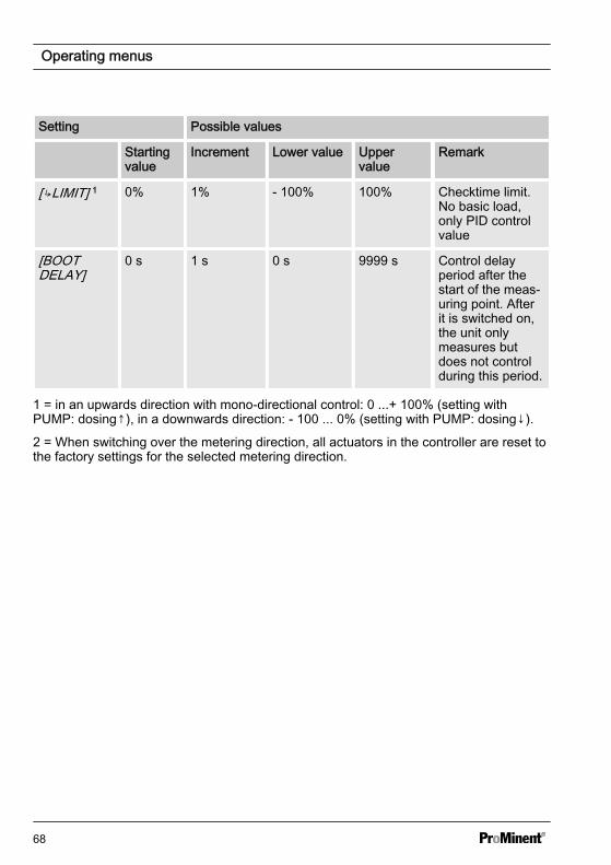
Setting Possible values
Startingvalue
Increment Lower value Uppervalue
Remark
[LIMIT] 1 0% 1% - 100% 100% Checktime limit.No basic load,only PID controlvalue
[BOOTDELAY]
0 s 1 s 0 s 9999 s Control delayperiod after thestart of the meas‐uring point. Afterit is switched on,the unit onlymeasures butdoes not controlduring this period.
1 = in an upwards direction with mono-directional control: 0 ...+ 100% (setting withPUMP: dosing↑), in a downwards direction: - 100 ... 0% (setting with PUMP: dosing↓).
2 = When switching over the metering direction, all actuators in the controller are reset tothe factory settings for the selected metering direction.
Operating menus
68
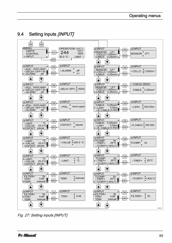
9.4 Setting inputs [INPUT]
A1622
MENU
≡MENULIMITSCONTROLINPUT
※INPUTSENSOR: LF1CELLC: 1.0000cm-1
※INPUT
SENSOR: LF1
※INPUT※INPUT
ℂ CHECK ZERO※INPUT
※INPUT ※INPUT
※INPUT ※INPUT
※INPUT ※INPUT
SENSOR: LF1
SENSOR: LF1
TCOEFF=1.90%/°C
※INPUT ※INPUT
CABLE: 0.25mm2
TCOMP:
CELLC: 1.0000cm-1
CABLE: 0.25mm2
CELLC: 1.0000cm-1
CELLC: 1.0000cm-1
CABLE: 0.25mm2CABLE: 0.25mm2
CABLE: 0.25mm2
LEN= R_CABLE=
3.00m0.40Ω
LEN= 003.00m
CABLE: 0.25mm2
LEN= R_CABLE=
3.00m0.40Ω
R_CABLE= 000.40Ω
TREF= 25°Clin
TCOMP: lin
TCOEFF=1.90%/°C
TCOMP:TREF= 25°C
linTREF= 25°C
※INPUT ※INPUT
TEMP:
FILTER=TDS= 0.64
3s
manualTDS= 0.64
※INPUT ※INPUT
TEMP:
FILTER=TDS= 0.64
3s
manualTEMP: manual
※INPUT ※INPUT
CONTACT25.0°C
°C
pause
°F
※INPUT ※INPUT
※INPUT ※INPUT
025.0 °C
UNIT: VALUE °CUNIT:
CONTACT25.0°C
°C
pause
UNIT: VALUE VALUE
CONTACT25.0°C
°C
pause
UNIT: VALUE CONTACT: pause
※INPUT ※INPUT norm.openPOL:
DELAY OFF= ALARM:
0soff
※INPUT ※INPUT norm.openPOL:
DELAY OFF= ALARM:
0soff
norm.openPOL:
※INPUT ※INPUT norm.openPOL:
DELAY OFF= ALARM:
0soff
DELAY OFF= 0000s
ALARM: offon
※INPUT ※INPUT
TCOEFF=1.90%/°C
TCOMP:TREF= 25°C
linTCOEFF= 1.90%/°C
※INPUT ※INPUT
TEMP:
FILTER=TDS= 0.64
3s
manualFILTER= 3s
Fig. 27: Setting inputs [INPUT]
Operating menus
69

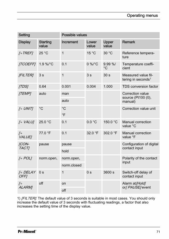
Setting Possible values
Display Startingvalue
Increment Lowervalue
Uppervalue
Remark
[SENSOR] LFTK1-3m Sensor type
[ TYPE] Conductive Sensor type
[ MIN] 0.0 S/cm 0.001 0.000uS/cm
2.000 S/cm
Minimum measuredvalue
[ MAX] 0.02 S/cm 0.001 0.000uS/cm
2.000 S/cm
Maximum measuredvalue
[ CELLC] 1 cm-1 0.001 0.006cm-1
15 cm-1 Cell constant
[ TMAX] 120 °C 0.01 0.01 °C 150 °C Maximum temperaturethat the sensor canwithstand
[ PRO‐FILE]
midCC lowCC, Automatic measuringrange detection
midCC
highCC
[CABLE] 0.25mm² 0.14mm² Cable diameter
0.34mm²
0.25mm²
0.50mm²
[ LEN] 3 m 0.01 0 m 50 m Cable length
[R_CABLE]
0.4 Ω 0.01 0 Ω 100 Ω Cable resistance
[TCOMP] off Temperature compen‐sation off
lin Linear temperaturecompensation
nLF Non-linear tempera‐ture compensation(according to DIN EN27888)
Operating menus
70
Setting Possible values
Display Startingvalue
Increment Lowervalue
Uppervalue
Remark
[TREF] 25 °C 1 15 °C 30 °C Reference tempera‐ture
[TCOEFF] 1.9 %/°C 0.1 0 %/°C 9.99 %/°C
Temperature coeffi‐cient
[FILTER] 3 s 1 3 s 30 s Measured value fil‐tering in seconds1
[TDS] 0.64 0.001 0.004 1.000 TDS conversion factor
[TEMP] auto man Correction valuesource (Pt100 (0),manual)auto
[ UNIT] °C °C
°F
Correction value unit
[ VALU] 25.0 °C 0.1 0.0 °C 150.0 °C Manual correctionvalue °C
[VALUE]
77.0 °F 0.1 32.0 °F 302.0 °F Manual correctionvalue °F
[CON‐TACT]
pause pause Configuration of digitalcontact input
hold
[ POL] norm.open, norm.open, Polarity of the contactinput
norm.closed
[ DELAYOFF]
0 s 1 0 s 3600 s Switch-off delay ofcontact input
[ALARM]
off on Alarm at[Hold]or[ PAUSE] event
off
1) [FILTER]: The default value of 3 seconds is suitable in most cases. You should onlyincrease the default value of 3 seconds with fluctuating readings, a factor that alsoincreases the setting time of the display value.
Operating menus
71

Sensor
Selection of the sensor con‐nectedIf the connected sensor it changed, allthe sensor-dependent settings arereset to their [DEFAULT] values.
Temperature sensor– [auto]: with conductivity sensors
with integral temperature sensor– [Manual], 25°C: with conductivity
sensors without integral tempera‐ture sensor
Operating menus
72
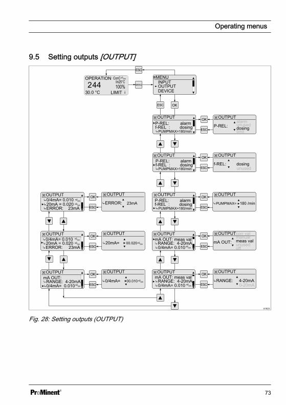
9.5 Setting outputs [OUTPUT]
A1623
MENU
≡MENU
DEVICEOUTPUTINPUT
※OUTPUTP-REL: alarm
PUMPMAX=180/min
※OUTPUT
P-REL:alarm
※OUTPUT※OUTPUT
※OUTPUT※OUTPUT
※OUTPUT ※OUTPUTmeas val
※OUTPUT ※OUTPUT
mA OUT: meas val mA OUT:
※OUTPUT ※OUTPUT
0/4mA= 0.01020mA = 0.020
※OUTPUT ※OUTPUT
0/4mA= 00.010
f-REL : dosing
PUMPMAX=180/min
PUMPMAX=180/min
f-REL: dosing
PUMPMAX= 180 /min
RANGE: 4-20mA
mA OUT: meas val
0/4mA= 0.010RANGE: 4-20mA
mA OUT:
0/4mA= 0.010RANGE: 4-20mA RANGE: 4-20mA
※OUTPUT ※OUTPUT
ERROR: 23mA
ERROR: 23mA
20mA = 0.020ERROR: 23mA
20mA= 00.020
P-REL: alarmf-REL : dosing
P-REL: alarmf-REL : dosing
limitdosingunused
unused
unusedoff
manualcorr val
0-20mA
0/4mA= 0.010
0/4mA= 0.010
Fig. 28: Setting outputs (OUTPUT)
Operating menus
73
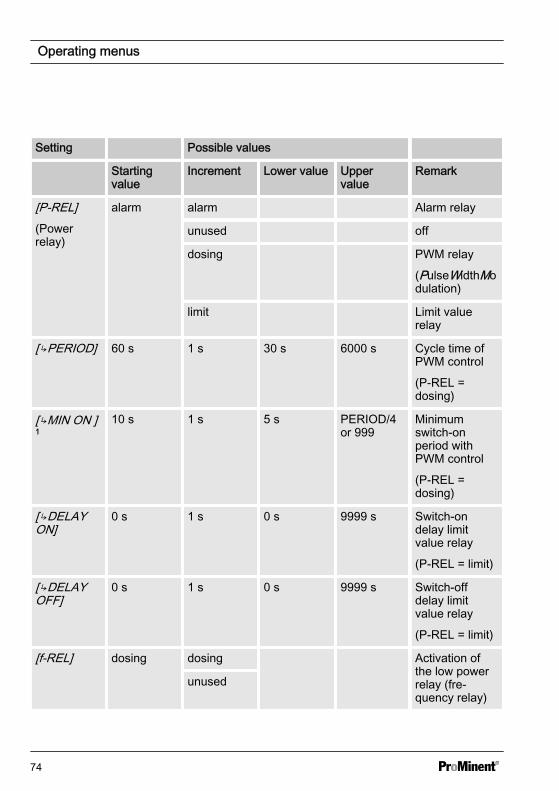
Setting Possible values
Startingvalue
Increment Lower value Uppervalue
Remark
[P-REL](Powerrelay)
alarm alarm Alarm relay
unused off
dosing PWM relay
(PulseWidthModulation)
limit Limit valuerelay
[PERIOD] 60 s 1 s 30 s 6000 s Cycle time ofPWM control
(P-REL =dosing)
[MIN ON ]1
10 s 1 s 5 s PERIOD/4or 999
Minimumswitch-onperiod withPWM control
(P-REL =dosing)
[DELAYON]
0 s 1 s 0 s 9999 s Switch-ondelay limitvalue relay
(P-REL = limit)
[DELAYOFF]
0 s 1 s 0 s 9999 s Switch-offdelay limitvalue relay
(P-REL = limit)
[f-REL] dosing dosing Activation ofthe low powerrelay (fre‐quency relay)
unused
Operating menus
74
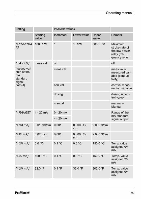
Setting Possible values
Startingvalue
Increment Lower value Uppervalue
Remark
[PUMPMAX]
180 RPM 1 1 RPM 500 RPM Maximumstroke rate ofthe low powerrelay (fre‐quency relay)
[mA OUT](Issued vari‐able of themAstandardsignaloutput)
meas val off off
meas val meas val =measured vari‐able (conduc‐tivity)
corr val corr val = cor‐rection variable
dosing dosing = con‐trol value
manual manual =Manual
[RANGE] 4 - 20 mA 0 - 20 mA Range of themA standardsignal output4 - 20 mA
[0/4 mA] 0.01 mS/cm 0.001 0.000 uS/cm
2.000 S/cm
[20 mA] 0.02 S/cm 0.001 0.000 uS/cm
2.000 S/cm
[0/4 mA] 0.0 °C 0.1 °C 0.0 °C 150.0 °C Temp valueassigned 0/4mA
[20 mA] 100.0 °C 0.1 °C 0.0 °C 150.0 °C Temp. valueassigned 20mA
[0/4 mA] 32.0 °F 0.1 °F 32.0 °F 302.0 °F Temp. valueassigned 0/4mA
Operating menus
75
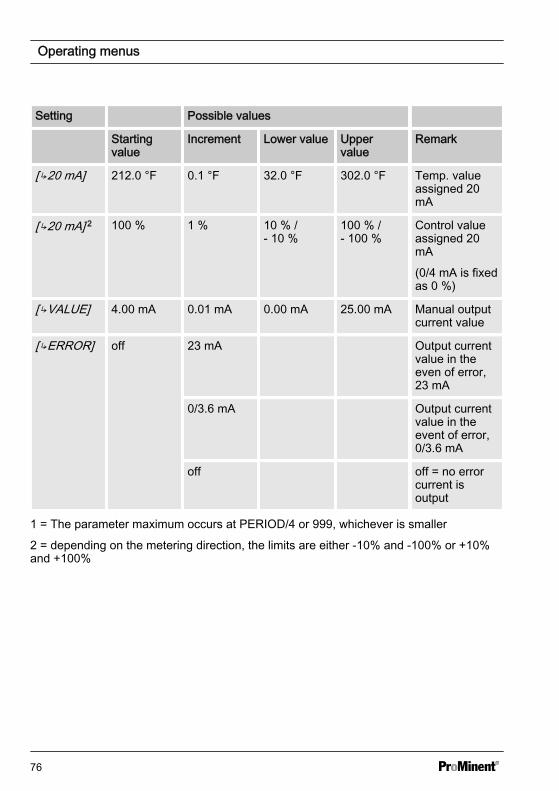
Setting Possible values
Startingvalue
Increment Lower value Uppervalue
Remark
[20 mA] 212.0 °F 0.1 °F 32.0 °F 302.0 °F Temp. valueassigned 20mA
[20 mA] 2 100 % 1 % 10 % /- 10 %
100 % /- 100 %
Control valueassigned 20mA
(0/4 mA is fixedas 0 %)
[VALUE] 4.00 mA 0.01 mA 0.00 mA 25.00 mA Manual outputcurrent value
[ERROR] off 23 mA Output currentvalue in theeven of error,23 mA
0/3.6 mA Output currentvalue in theevent of error,0/3.6 mA
off off = no errorcurrent isoutput
1 = The parameter maximum occurs at PERIOD/4 or 999, whichever is smaller
2 = depending on the metering direction, the limits are either -10% and -100% or +10%and +100%
Operating menus
76
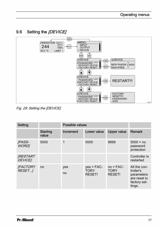
9.6 Setting the [DEVICE]
A1624
MENU
≡MENU
DEVICEOUTPUTINPUT
※DEVICEPASSWORD: ****
※DEVICE
NEW PASSW. 5000=FREE
※DEVICE
RESTART DEVICE...
PASSWORD: ****RESTART DEVICE... RESTART!!!
5000
※DEVICEPASSWORD: ****RESTART DEVICE...
FACTORY RESET!!!!
FACTORY RESET...
FACTORY RESET...
FACTORY RESET...PASSWORD: 5000
Fig. 29: Setting the [DEVICE]
Setting Possible values
Startingvalue
Increment Lower value Upper value Remark
[PASS‐WORD]
5000 1 0000 9999 5000 = nopasswordprotection
[RESTARTDEVICE]
Controller isrestarted
[FACTORYRESET...]
no yes
no
yes = FAC‐TORYRESET!
no = FAC‐TORYRESET!
All the con‐troller'sparametersare reset tofactory set‐tings.
Operating menus
77
10 Control parameters and functionsn User qualification: trained user, see
Ä Chapter 3.4 ‘Users' qualifications’on page 14
10.1 DULCOMETER® Com‐pact Controller functionstates
DULCOMETER® Compact Controllerfunction states have the following priority:
n 1. ‘STOP’n 2. ‘PAUSE/HOLD’n 3. ‘CAL’ (calibration)n 4. ‘OPERATION’ (normal mode)
"CAL" (calibration) peculiarities
n Control goes to basic load, mA meas‐urement outputs are frozen
n New faults are detected, howeverthey have no effect on the alarm relayor the mA output
n Detection of measurement variablerelevant faults during ‘CAL’ (calibra‐tion process) are suppressed (e.g.LIMIT↑)
"PAUSE" peculiarities
n Control is switched to 0% control vari‐able. The I-proportion is saved
n New faults are detected, howeverthey have no effect on the alarm relayor the mA output
n Special case alarm relay in ‘PAUSE’ :If activated the output relay switchesto ‘PAUSE’ (error message CON‐TACTIN)
"HOLD" peculiarities
n Control and all other outputs arefrozen
n New faults are detected, howeverthey have no effect on the alarm relayor the mA output. However the effectof already existing faults (e.g. faultcurrent) remains
n Special case alarm relay: Activation ofthe frozen alarm relay is permitted (=no alarm), if all faults have beenacknowledged or have disappeared
n Special case alarm relay in ‘HOLD’ : Ifactivated the output relay switches to‘HOLD’ (error message CON‐TACTIN)
"STOP" peculiarities
n Control OFFn New faults are detected, however
they have no effect on the alarm relayor the mA output
n The alarm relay is switched off in‘STOP’
Peculiarities of the "START" event, i.e.switching from "STOP" to "OPERATION"(normal mode)
n Fault detection starts afresh, allexisting faults are deleted
Generally applicable information
n If the cause of a fault disappears,then the fault message in the LCDfooter disappears.
n A previously existing ‘ PAUSE/HOLD’state is not influenced by starting a‘CAL’ (calibration) process. If during‘CAL’ (calibration) the functional state‘ PAUSE/HOLD’ is released, then allstates will remain frozen until the endof the ‘CAL’ (calibration) process.
Control parameters and functions
78

n If ‘CAL’ (calibration) is started whilefunctional state ‘ OPERATION’(normal mode) is active, then thefunctional state ‘ PAUSE/HOLD’ isignored until ‘CAL’ (calibration) com‐pletes. However STOP/START ispossible at any time
n An alarm can be acknowledged orremoved as follows: By clearing allfaults by pressing the key and the
key while the continuous display isvisible
Control parameters and functions
79
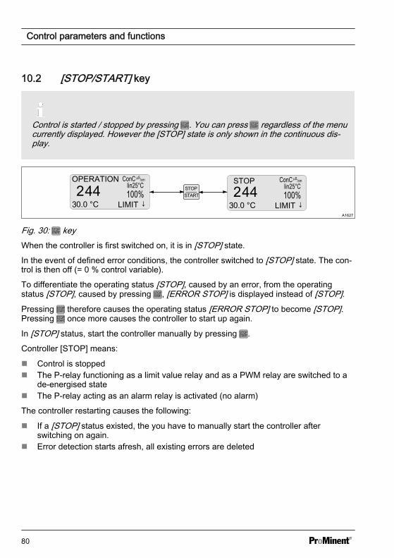
10.2 [STOP/START] key
Control is started / stopped by pressing . You can press regardless of the menucurrently displayed. However the [STOP] state is only shown in the continuous dis‐play.
A1627
STOP
Fig. 30: keyWhen the controller is first switched on, it is in [STOP] state.
In the event of defined error conditions, the controller switched to [STOP] state. The con‐trol is then off (= 0 % control variable).
To differentiate the operating status [STOP], caused by an error, from the operatingstatus [STOP], caused by pressing , [ERROR STOP] is displayed instead of [STOP].Pressing therefore causes the operating status [ERROR STOP] to become [STOP].Pressing once more causes the controller to start up again.
In [STOP] status, start the controller manually by pressing .
Controller [STOP] means:
n Control is stoppedn The P-relay functioning as a limit value relay and as a PWM relay are switched to a
de-energised staten The P-relay acting as an alarm relay is activated (no alarm)
The controller restarting causes the following:
n If a [STOP] status existed, the you have to manually start the controller afterswitching on again.
n Error detection starts afresh, all existing errors are deleted
Control parameters and functions
80
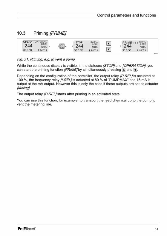
10.3 Priming [PRIME]
A1628
STOP PRIME↑↑↑
Fig. 31: Priming, e.g. to vent a pumpWhile the continuous display is visible, in the statuses [STOP] and [OPERATION], youcan start the priming function [PRIME] by simultaneously pressing and .
Depending on the configuration of the controller, the output relay [P-REL] is actuated at100 %, the frequency relay [f-REL] is actuated at 80 % of "PUMPMAX" and 16 mA isoutput at the mA output. However this is only the case if these outputs are set as actuator[dosing].The output relay [P-REL] starts after priming in an activated state.
You can use this function, for example, to transport the feed chemical up to the pump tovent the metering line.
Control parameters and functions
81
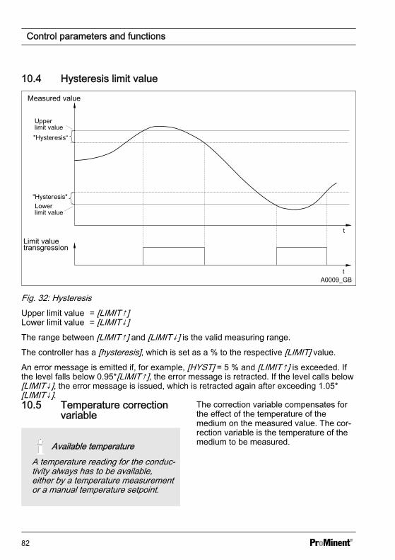
10.4 Hysteresis limit value
Measured value
Limit valuetransgression
Upperlimit value
"Hysteresis"
t
t
"Hysteresis“
Lowerlimit value
A0009_GB
Fig. 32: HysteresisUpper limit value = [LIMIT↑]Lower limit value = [LIMIT↓]The range between [LIMIT↑] and [LIMIT↓] is the valid measuring range.
The controller has a [hysteresis], which is set as a % to the respective [LIMIT] value.
An error message is emitted if, for example, [HYST] = 5 % and [LIMIT↑] is exceeded. Ifthe level falls below 0.95*[LIMIT↑], the error message is retracted. If the level calls below[LIMIT↓], the error message is issued, which is retracted again after exceeding 1.05*[LIMIT↓].10.5 Temperature correction
variable
Available temperatureA temperature reading for the conduc‐tivity always has to be available,either by a temperature measurementor a manual temperature setpoint.
The correction variable compensates forthe effect of the temperature of themedium on the measured value. The cor‐rection variable is the temperature of themedium to be measured.
Control parameters and functions
82

Operating modes
n [auto]: The controller analyses thetemperature signal from the tempera‐ture sensor connected– For measurements using a tem‐
perature sensor (0 ... 150 °C)n [manual]: The temperature of the
medium to be measured has to bemeasured by the user. The deter‐mined value is then entered using thekeys: and in the [VALUE]parameter into the controller and issaved using .– This setting is needed for meas‐
urements where the medium tobe measured has a constant tem‐perature. The temperature istaken into consideration in thecontrol.
Control parameters and functions
83
10.6 Checkout time for measured variable and correction variable
Error text Description
LIMIT ERR Checkout time of the measured variable
TLIMITERR Checkout time of the correction variable
If upon the expiry of the checkout time, the valid measuring range is not reached, thenthe DULCOMETER® Compact Controller exhibits the following behaviour:
n LIMIT ERR: The control is switched off. An error current is emitted, provided theoutput is configured as a measured variable output
n TLIMITERR: The control is switched off. An error current is emitted, provided theoutput is configured as a correction variable output or a measured variable output
Initially the transgression of a limit is only a limit value transgression. This leads to a‘WARNING’ . Switching on the control time ‘TIMELIM’ (> 0 minutes), creates an alarmfrom the limit value transgression. In the event of a [TLIMITERR] a, the control switchesto [STOP].10.7 Checkout time control
Monitoring of the control pathThe checkout time monitors the con‐trol path. The checkout time mecha‐nism permits detection of possibledefective sensors.
Dead time determination
Each control path has a dead time. Thedead time is the time, which the controlpath requires to detect a change or addi‐tion of metered chemicals using its owninstrumentation.
You must select the checkout time so thatit is greater than the dead time. You candetermine the dead time, by operating themetering pump in manual mode and, forexample, dosing acid.
NOTICE!
Dead time determinationYou should only determine the deadtime if the current process cannot benegatively influenced by the manualmetering.
You must determine the time, which thecontrol path (i.e. the entirety of controllers,sensors, measurement water, flowgauges, etc.) requires to detect a firstchange in the measured value startingfrom the beginning of dosing. This time isthe ‘dead time’ . A safety margin, e.g.25%, must be added to this dead time.You must allocate an appropriate safetymargin for your own particular process.
The parameter ‘LIMIT’ can be used to seta limit for the control variable. If the con‐trol variable exceeds this limit value, theCHECKTIME fault is triggered (checkouttime of the control has elapsed). The con‐trol is switched to basic load and a faultcurrent output.
Control parameters and functions
84

10.8 Power relay "P-REL" aslimit value relay
The power relay ‘P-REL’ can be config‐ured as a limit value relay. It always actonly on the measurement variable,whereby the limits are set in ‘LIMITS’ .The relay is activated upon infringementof either the top or lower limit values.
Constant checking is carried out to deter‐mine whether a limit has been infringedand if this is interrupted with the powerrelay configured ‘P-REL= limit’ for at least‘DELAY ON’ seconds, then the relay isactivated. If the limit value transgressiondisappears for at least ‘DELAY OFF’ sec‐onds, then the limit value relay is againdeactivated.
The limit value relay is deactivated imme‐diately upon: ‘STOP’ , user calibration,‘PAUSE’ and ‘HOLD’ .
Control parameters and functions
85
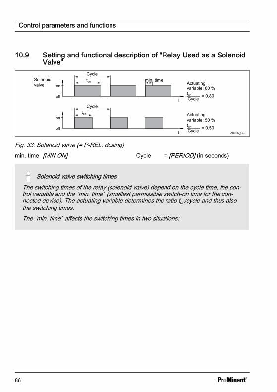
10.9 Setting and functional description of "Relay Used as a SolenoidValve"
Cyclemin. timeSolenoid
valve
off
on
t
ton
off
on
t
ton
Cycle
Actuatingvariable: 50 %ton
Cycle = 0.50
Actuatingvariable: 80 %ton
Cycle = 0.80
A0025_GB
Fig. 33: Solenoid valve (= P-REL: dosing)min. time [MIN ON] Cycle = [PERIOD] (in seconds)
Solenoid valve switching timesThe switching times of the relay (solenoid valve) depend on the cycle time, the con‐trol variable and the ‘min. time’ (smallest permissible switch-on time for the con‐nected device). The actuating variable determines the ratio ton/cycle and thus alsothe switching times.The ‘min. time’ affects the switching times in two situations:
Control parameters and functions
86
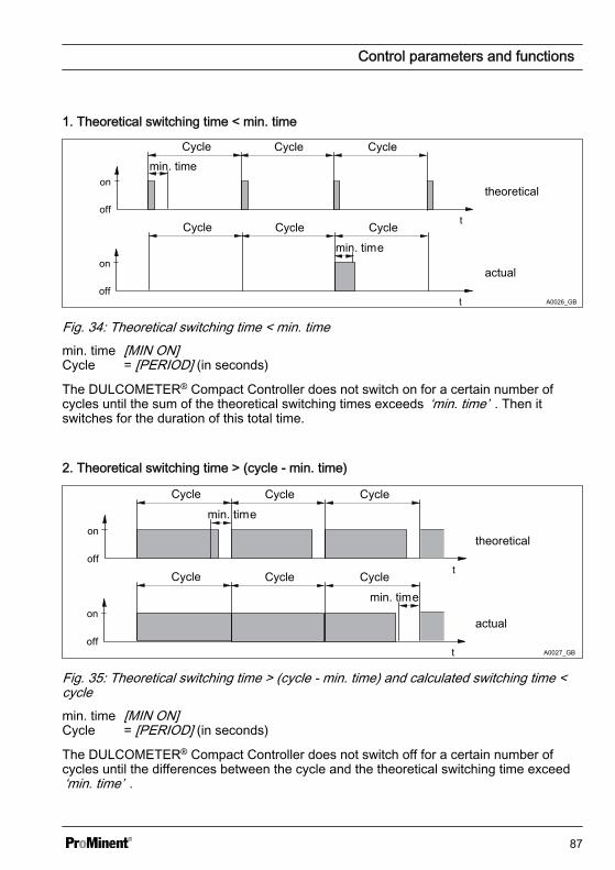
1. Theoretical switching time < min. time
off
on
t
off
on
t
Cycle Cycle Cycle
Cycle Cycle Cycle
min. time
min. time
theoretical
actual
A0026_GB
Fig. 34: Theoretical switching time < min. timemin. time [MIN ON]Cycle = [PERIOD] (in seconds)
The DULCOMETER® Compact Controller does not switch on for a certain number ofcycles until the sum of the theoretical switching times exceeds ‘min. time’ . Then itswitches for the duration of this total time.
2. Theoretical switching time > (cycle - min. time)
Cycle
min. time
off
on
t
off
on
t
Cycle Cycle
Cycle Cycle Cycle
min. time
theoretical
actual
A0027_GB
Fig. 35: Theoretical switching time > (cycle - min. time) and calculated switching time <cyclemin. time [MIN ON]Cycle = [PERIOD] (in seconds)
The DULCOMETER® Compact Controller does not switch off for a certain number ofcycles until the differences between the cycle and the theoretical switching time exceed‘min. time’ .
Control parameters and functions
87
10.10 Alarm relayThe alarm relay triggers in ‘OPERATION’(normal mode) if an error occurs whichhas been defined as ‘ERROR’ and notjust as ‘WARNING’ .The error message ‘ALARM’ in the con‐tinuous display is marked with a (star)and can be acknowledged with the key.The alarm and the will then disappear.
10.11 "Error logger" operatingmode
The last three errors are displayed. Alsodisplayed is how long ago (in minutes)they occurred. When a new fault occurs,the oldest fault is deleted.
Faults are only shown which occur inoperating status ‘OPERATION’ , i.e. not inoperating status ‘STOP’ , ‘CAL’ (user cali‐bration), ‘HOLD’ or ‘ PAUSE’ .Only ‘ERRORs’ are shown, not‘WARNINGS’ , e.g. a ‘LIMIT ERR’ isshown, but not ‘ LIMIT↑’ .A fault, whose display has lasted for 999minutes is automatically deleted from the‘Error Logger’ . The ‘Error Logger’ is nei‐ther saved nor backed up in the event ofpower loss.
Control parameters and functions
88
11 Maintenancen User qualification: trained user, see
Ä Chapter 3.4 ‘Users' qualifications’on page 14
The controller is maintenance- free.
11.1 Error messagesn User qualification for diagnosis:
trained user, see Ä Chapter 3.4‘Users' qualifications’ on page 14.Further qualifications depend on thetype and scope of possible trouble‐shooting measures to be carried out.
Measuring technology-specificerrors: [INPUT↑]The electrical sensor signal directlyon the conductivity sensor input is toohigh. The conductivity calculated isless than that actual conductivity reg‐istered.The error occurs from a value of:– 200mS/cm with sensors with cell
constant 1.0– 20mS/cm with sensors with cell
constant 0.1– 2mS/cm with sensors with cell
constant 0.01The specified limit can also be higherdepending on the sensor.
Measured variable-specificerrors: [TDS ↑]>2000: If the calculated TDS value isover 2000.
Measured variable-specificerrors: [SAL ↑]>70: If the calculated SAL value isover 70.
Error detection following devicestartThe majority of errors are only dis‐played with a 10-second delay fol‐lowing the start-up of the device.
Maintenance
89
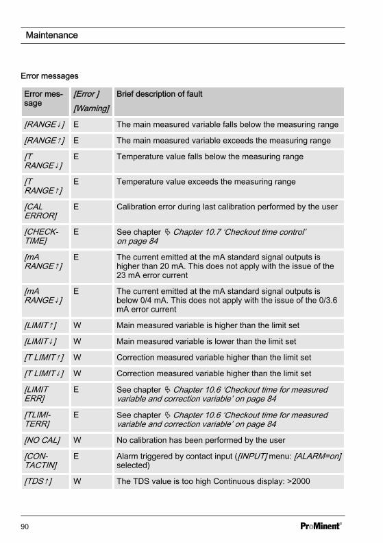
Error messages
Error mes‐sage
[Error ][Warning]
Brief description of fault
[RANGE↓] E The main measured variable falls below the measuring range
[RANGE↑] E The main measured variable exceeds the measuring range
[TRANGE↓]
E Temperature value falls below the measuring range
[TRANGE↑]
E Temperature value exceeds the measuring range
[CALERROR]
E Calibration error during last calibration performed by the user
[CHECK‐TIME]
E See chapter Ä Chapter 10.7 ‘Checkout time control’on page 84
[mARANGE↑]
E The current emitted at the mA standard signal outputs ishigher than 20 mA. This does not apply with the issue of the23 mA error current
[mARANGE↓]
E The current emitted at the mA standard signal outputs isbelow 0/4 mA. This does not apply with the issue of the 0/3.6mA error current
[LIMIT↑] W Main measured variable is higher than the limit set
[LIMIT↓] W Main measured variable is lower than the limit set
[T LIMIT↑] W Correction measured variable higher than the limit set
[T LIMIT↓] W Correction measured variable higher than the limit set
[LIMITERR]
E See chapter Ä Chapter 10.6 ‘Checkout time for measuredvariable and correction variable’ on page 84
[TLIMI‐TERR]
E See chapter Ä Chapter 10.6 ‘Checkout time for measuredvariable and correction variable’ on page 84
[NO CAL] W No calibration has been performed by the user
[CON‐TACTIN]
E Alarm triggered by contact input ([INPUT] menu: [ALARM=on]selected)
[TDS↑] W The TDS value is too high Continuous display: >2000
Maintenance
90
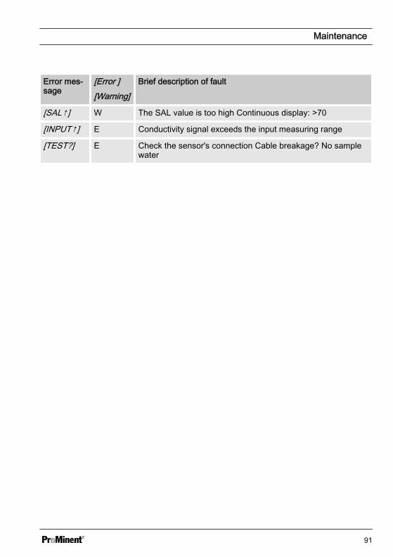
Error mes‐sage
[Error ][Warning]
Brief description of fault
[SAL↑] W The SAL value is too high Continuous display: >70
[INPUT↑] E Conductivity signal exceeds the input measuring range
[TEST?] E Check the sensor's connection Cable breakage? No samplewater
Maintenance
91
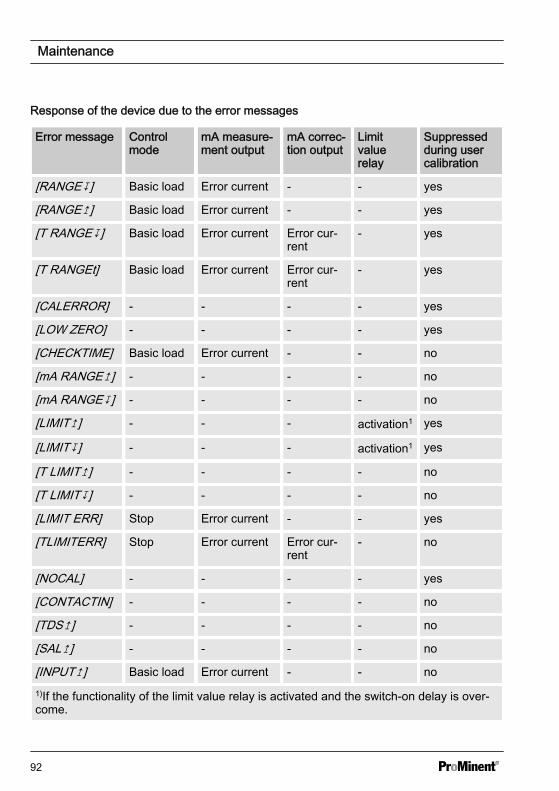
Response of the device due to the error messages
Error message Controlmode
mA measure‐ment output
mA correc‐tion output
Limitvaluerelay
Suppressedduring usercalibration
[RANGE] Basic load Error current - - yes
[RANGE] Basic load Error current - - yes
[T RANGE] Basic load Error current Error cur‐rent
- yes
[T RANGEt] Basic load Error current Error cur‐rent
- yes
[CALERROR] - - - - yes
[LOW ZERO] - - - - yes
[CHECKTIME] Basic load Error current - - no
[mA RANGE] - - - - no
[mA RANGE] - - - - no
[LIMIT] - - - activation1 yes
[LIMIT] - - - activation1 yes
[T LIMIT] - - - - no
[T LIMIT] - - - - no
[LIMIT ERR] Stop Error current - - yes
[TLIMITERR] Stop Error current Error cur‐rent
- no
[NOCAL] - - - - yes
[CONTACTIN] - - - - no
[TDS] - - - - no
[SAL] - - - - no
[INPUT] Basic load Error current - - no1)If the functionality of the limit value relay is activated and the switch-on delay is over‐come.
Maintenance
92
11.2 Changing the fuse,DULCOMETER® Com‐pact Controller
WARNING!
Danger from electrical voltagePossible consequence: Fatal or veryserious injuries.
– The DULCOMETER® CompactController does not have a mainsswitch
– When working inside the controlunit, disconnect the control unitfrom the mains power via anexternal switch or by removingthe external fuse
NOTICE!
Use only 5 x 20 mm micro-fusesPossible consequence: Damage tothe product or its surroundings
– 5x20 T 0.315 A– Part number 732404
Fuse change
The mains fuse is located in a sealed fuseholder in the inside of the device.
1. Disconnect the controller from themains power
2. Open the controller and fold thecontroller housing top section to theleft
3. Remove the PCB cover
4. Remove the micro-fuse using asuitable tool
5. Fit the micro-fuse using a suitabletool
6. Refit the PCB cover
7. Replace controller housing top sec‐tion and close the controller
Maintenance
93
12 Technical data on DULCOMETER® Compact Controller12.1 Permissible ambient conditions
Degree of protection (IP)The controller fulfils the IP 67 degree of protection requirements (wall/pipe mounting)or IP 54 (control panel mounting). This degree of protection is only achieved if allseals and threaded connectors are correctly fitted.
Permissible ambient operating conditions
Temperature -10 °C ... 60 °C
Air humidity < 95 % relative air humidity (non-con‐densing)
Permissible ambient storage conditions
Temperature -20 °C ... 70 °C
Air humidity < 95 % relative air humidity (non-con‐densing)
12.2 Dimensions and weights
Complete device: 128 x 137 x 76 mm (W x H x D)
Packaging: 220 x 180 x 100 mm (W x H x D)
Weight of device without packaging: approx. 0.5 kg
Gross weight of device with packaging: approx. 0.8 kg
Technical data on DULCOMETER® Compact Controller
94
12.3 Material data
Part Material
Housing lower and upper section PC-GF10
Bracket rear side housing bottom section PPE-GF20
Operating film Polyester PET membrane
Seal Expanded PUR
Cover screws Stainless steel A2
Profile seal (control panel mounting) Silicone12.4 Chemical ResistanceThe device is resistant to normal atmos‐pheres in plant rooms
12.5 Sound Pressure LevelNo noise generation measurable
Technical data on DULCOMETER® Compact Controller
95
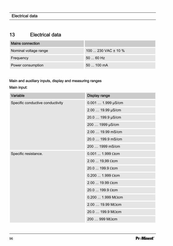
13 Electrical dataMains connection
Nominal voltage range 100 ... 230 VAC ± 10 %
Frequency 50 ... 60 Hz
Power consumption 50 ... 100 mA
Main and auxiliary inputs, display and measuring ranges
Main input:
Variable Display range
Specific conductive conductivity 0.001 … 1.999 µS/cm
2.00 … 19.99 µS/cm
20.0 … 199.9 µS/cm
200 … 1999 µS/cm
2.00 … 19.99 mS/cm
20.0 … 199.9 mS/cm
200 … 1999 mS/cm
Specific resistance. 0.001 ... 1.999 Ωcm
2.00 ... 19,99 Ωcm
20.0 ... 199.9 Ωcm
0.200 ... 1.999 Ωcm
2.00 ... 19.99 Ωcm
20.0 ... 199.9 Ωcm
0.200 ... 1.999 MΩcm
2.00 … 19.99 MΩcm
20.0 … 199.9 MΩcm
200 … 999 MΩcm
Electrical data
96
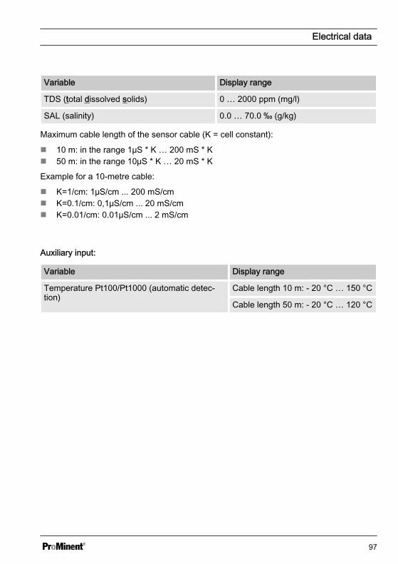
Variable Display range
TDS (total dissolved solids) 0 … 2000 ppm (mg/l)
SAL (salinity) 0.0 … 70.0 ‰ (g/kg)
Maximum cable length of the sensor cable (K = cell constant):
n 10 m: in the range 1μS * K … 200 mS * Kn 50 m: in the range 10μS * K … 20 mS * K
Example for a 10-metre cable:
n K=1/cm: 1μS/cm ... 200 mS/cmn K=0.1/cm: 0,1μS/cm ... 20 mS/cmn K=0.01/cm: 0.01μS/cm ... 2 mS/cm
Auxiliary input:
Variable Display range
Temperature Pt100/Pt1000 (automatic detec‐tion)
Cable length 10 m: - 20 °C … 150 °C
Cable length 50 m: - 20 °C … 120 °C
Electrical data
97
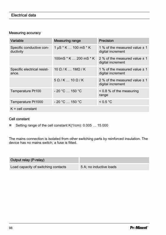
Measuring accuracy
Variable Measuring range Precision
Specific conductive con‐ductivity
1 μS * K … 100 mS * K 1 % of the measured value ± 1digital increment
100mS * K … 200 mS * K 2 % of the measured value ± 1digital increment
Specific electrical resist‐ance.
10 Ω / K … 1MΩ / K 1 % of the measured value ± 1digital increment
5 Ω / K … 10 Ω / K 2 % of the measured value ± 1digital increment
Temperature Pt100 - 20 °C … 150 °C < 0.8 % of the measuringrange
Temperature Pt1000 - 20 °C … 150 °C < 0.5 °C
K = cell constant
Cell constant
n Setting range of the cell constant K(1/cm): 0.005 … 15.000
The mains connection is isolated from other switching parts by reinforced insulation. Thedevice has no mains switch; a fuse is fitted.
Output relay (P-relay)
Load capacity of switching contacts 5 A; no inductive loads
Electrical data
98
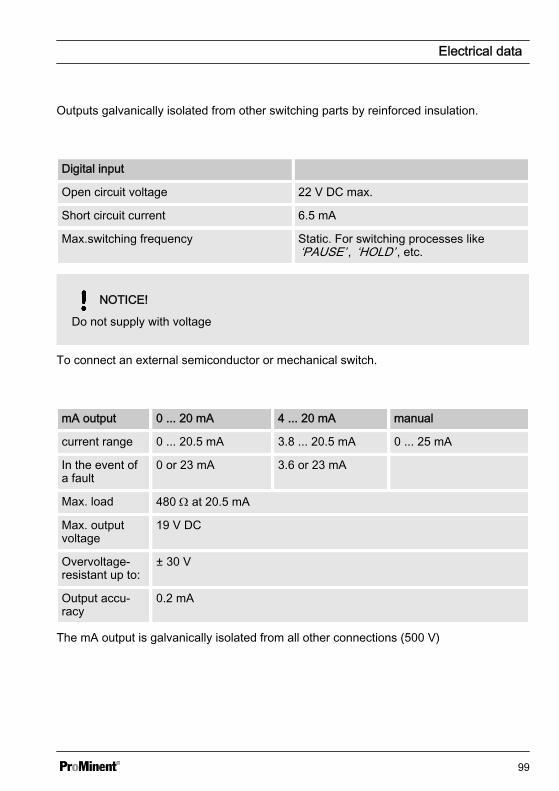
Outputs galvanically isolated from other switching parts by reinforced insulation.
Digital input
Open circuit voltage 22 V DC max.
Short circuit current 6.5 mA
Max.switching frequency Static. For switching processes like‘PAUSE’ , ‘HOLD’ , etc.
NOTICE!
Do not supply with voltage
To connect an external semiconductor or mechanical switch.
mA output 0 ... 20 mA 4 ... 20 mA manual
current range 0 ... 20.5 mA 3.8 ... 20.5 mA 0 ... 25 mA
In the event ofa fault
0 or 23 mA 3.6 or 23 mA
Max. load 480 W at 20.5 mA
Max. outputvoltage
19 V DC
Overvoltage-resistant up to:
± 30 V
Output accu‐racy
0.2 mA
The mA output is galvanically isolated from all other connections (500 V)
Electrical data
99
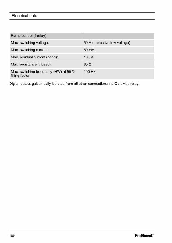
Pump control (f-relay)
Max. switching voltage: 50 V (protective low voltage)
Max. switching current: 50 mA
Max. residual current (open): 10 mA
Max. resistance (closed): 60 W
Max. switching frequency (HW) at 50 %filling factor
100 Hz
Digital output galvanically isolated from all other connections via OptoMos relay.
Electrical data
100
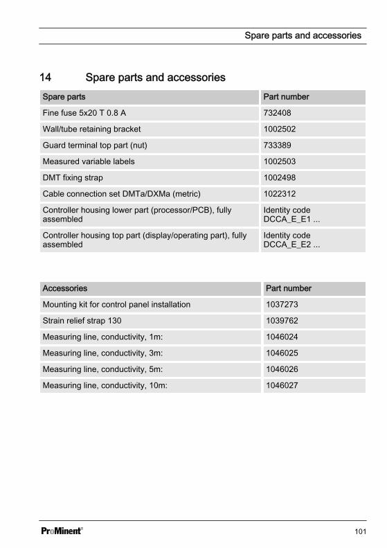
14 Spare parts and accessoriesSpare parts Part number
Fine fuse 5x20 T 0.8 A 732408
Wall/tube retaining bracket 1002502
Guard terminal top part (nut) 733389
Measured variable labels 1002503
DMT fixing strap 1002498
Cable connection set DMTa/DXMa (metric) 1022312
Controller housing lower part (processor/PCB), fullyassembled
Identity codeDCCA_E_E1 ...
Controller housing top part (display/operating part), fullyassembled
Identity codeDCCA_E_E2 ...
Accessories Part number
Mounting kit for control panel installation 1037273
Strain relief strap 130 1039762
Measuring line, conductivity, 1m: 1046024
Measuring line, conductivity, 3m: 1046025
Measuring line, conductivity, 5m: 1046026
Measuring line, conductivity, 10m: 1046027
Spare parts and accessories
101
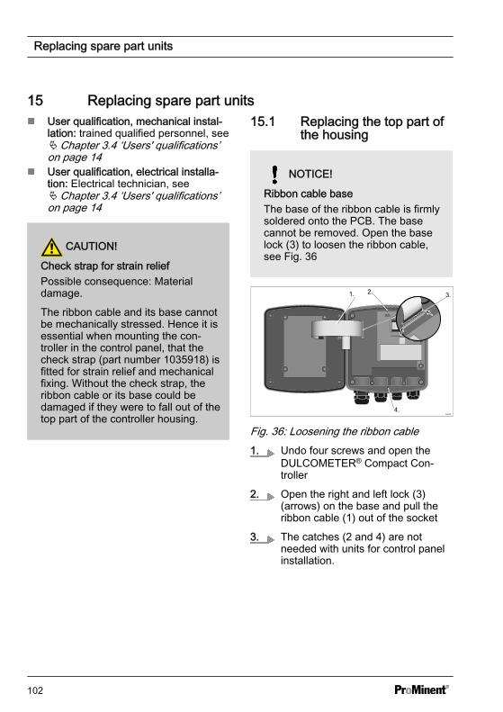
15 Replacing spare part unitsn User qualification, mechanical instal‐
lation: trained qualified personnel, seeÄ Chapter 3.4 ‘Users' qualifications’on page 14
n User qualification, electrical installa‐tion: Electrical technician, seeÄ Chapter 3.4 ‘Users' qualifications’on page 14
CAUTION!
Check strap for strain reliefPossible consequence: Materialdamage.
The ribbon cable and its base cannotbe mechanically stressed. Hence it isessential when mounting the con‐troller in the control panel, that thecheck strap (part number 1035918) isfitted for strain relief and mechanicalfixing. Without the check strap, theribbon cable or its base could bedamaged if they were to fall out of thetop part of the controller housing.
15.1 Replacing the top part ofthe housing
NOTICE!
Ribbon cable baseThe base of the ribbon cable is firmlysoldered onto the PCB. The basecannot be removed. Open the baselock (3) to loosen the ribbon cable,see Fig. 36
1. 2. 3.
4.
Fig. 36: Loosening the ribbon cable1. Undo four screws and open the
DULCOMETER® Compact Con‐troller
2. Open the right and left lock (3)(arrows) on the base and pull theribbon cable (1) out of the socket
3. The catches (2 and 4) are notneeded with units for control panelinstallation.
Replacing spare part units
102
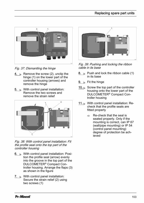
1.2.
Fig. 37: Dismantling the hinge4. Remove the screw (2), unclip the
hinge (1) on the lower part of thecontroller housing (arrows) andremove the hinge
5. With control panel installation:Remove the two screws andremove the strain relief
A0351
1.
2.1.
Fig. 38: With control panel installation: Fitthe profile seal onto the top part of thecontroller housing6. With control panel installation: Posi‐
tion the profile seal (arrow) evenlyinto the groove in the top part of theDULCOMETER® Compact Con‐troller housing. Arrange the flaps (3)as shown in the figure
7. With control panel installation:Secure the strain relief (2) usingtwo screws (1)
A0352
1.
Fig. 39: Pushing and locking the ribboncable in its base8. Push and lock the ribbon cable (1)
in its base
9. Fit the hinge
10. Screw the top part of the controllerhousing onto the lower part of theDULCOMETER® Compact Con‐troller housing
11. With control panel installation: Re-check that the profile seals arefitted properly
ð Re-check that the seal isseated properly. Only if themounting is correct, can IP 67(wall/pipe mounting) or IP 54(control panel mounting)degree of protection be ach‐ieved
Replacing spare part units
103
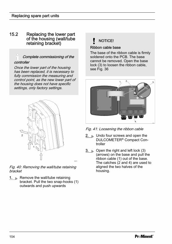
15.2 Replacing the lower partof the housing (wall/tuberetaining bracket)
Complete commissioning of thecontrollerOnce the lower part of the housinghas been replaced, it is necessary tofully commission the measuring andcontrol point, as the new lower part ofthe housing does not have specificsettings, only factory settings.
2
1
A0273
Fig. 40: Removing the wall/tube retainingbracket1. Remove the wall/tube retaining
bracket. Pull the two snap-hooks (1)outwards and push upwards
NOTICE!
Ribbon cable baseThe base of the ribbon cable is firmlysoldered onto the PCB. The basecannot be removed. Open the baselock (3) to loosen the ribbon cable,see Fig. 36
1. 2. 3.
4.
Fig. 41: Loosening the ribbon cable2. Undo four screws and open the
DULCOMETER® Compact Con‐troller
3. Open the right and left lock (3)(arrows) on the base and pull theribbon cable (1) out of the base.The catches (2 and 4) are used toaligned the two halves of thehousing.
Replacing spare part units
104
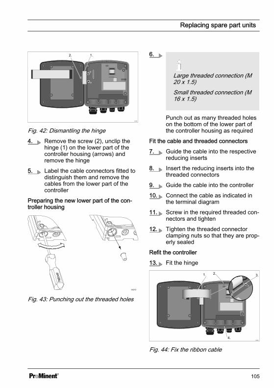
1.2.
Fig. 42: Dismantling the hinge4. Remove the screw (2), unclip the
hinge (1) on the lower part of thecontroller housing (arrows) andremove the hinge
5. Label the cable connectors fitted todistinguish them and remove thecables from the lower part of thecontroller
Preparing the new lower part of the con‐troller housing
A0272
Fig. 43: Punching out the threaded holes
6.
Large threaded connection (M20 x 1.5)Small threaded connection (M16 x 1.5)
Punch out as many threaded holeson the bottom of the lower part ofthe controller housing as required
Fit the cable and threaded connectors
7. Guide the cable into the respectivereducing inserts
8. Insert the reducing inserts into thethreaded connectors
9. Guide the cable into the controller
10. Connect the cable as indicated inthe terminal diagram
11. Screw in the required threaded con‐nectors and tighten
12. Tighten the threaded connectorclamping nuts so that they are prop‐erly sealed
Refit the controller
13. Fit the hinge
1. 2. 3.
4.
Fig. 44: Fix the ribbon cable
Replacing spare part units
105
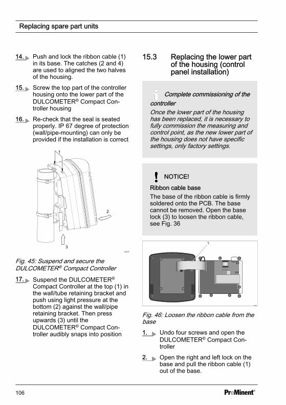
14. Push and lock the ribbon cable (1)in its base. The catches (2 and 4)are used to aligned the two halvesof the housing.
15. Screw the top part of the controllerhousing onto the lower part of theDULCOMETER® Compact Con‐troller housing
16. Re-check that the seal is seatedproperly. IP 67 degree of protection(wall/pipe-mounting) can only beprovided if the installation is correct
A0275
3
2
1
Fig. 45: Suspend and secure theDULCOMETER® Compact Controller17. Suspend the DULCOMETER®
Compact Controller at the top (1) inthe wall/tube retaining bracket andpush using light pressure at thebottom (2) against the wall/piperetaining bracket. Then pressupwards (3) until theDULCOMETER® Compact Con‐troller audibly snaps into position
15.3 Replacing the lower partof the housing (controlpanel installation)
Complete commissioning of thecontrollerOnce the lower part of the housinghas been replaced, it is necessary tofully commission the measuring andcontrol point, as the new lower part ofthe housing does not have specificsettings, only factory settings.
NOTICE!
Ribbon cable baseThe base of the ribbon cable is firmlysoldered onto the PCB. The basecannot be removed. Open the baselock (3) to loosen the ribbon cable,see Fig. 36
A0352
1.
Fig. 46: Loosen the ribbon cable from thebase1. Undo four screws and open the
DULCOMETER® Compact Con‐troller
2. Open the right and left lock on thebase and pull the ribbon cable (1)out of the base.
Replacing spare part units
106
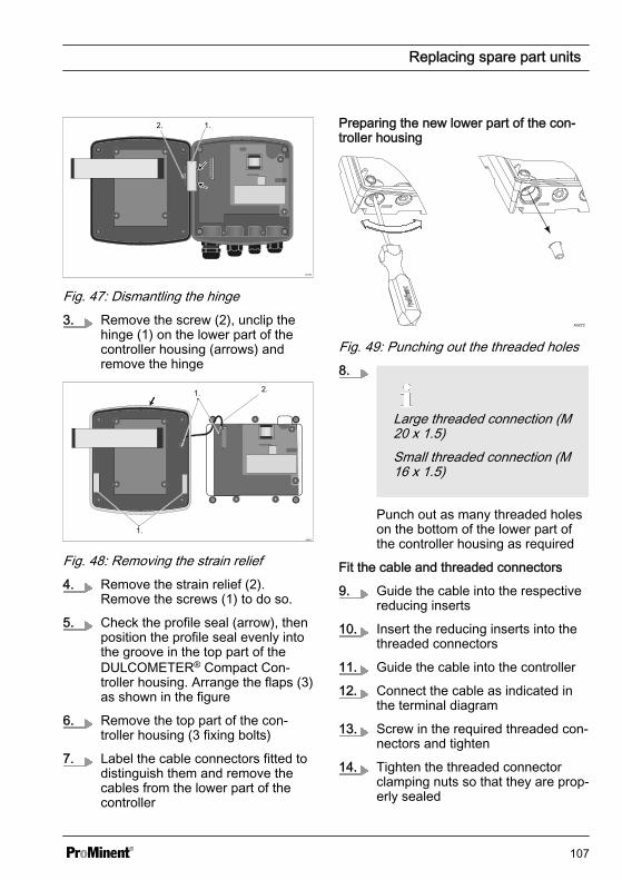
1.2.
Fig. 47: Dismantling the hinge3. Remove the screw (2), unclip the
hinge (1) on the lower part of thecontroller housing (arrows) andremove the hinge
A0351
1.
2.1.
Fig. 48: Removing the strain relief4. Remove the strain relief (2).
Remove the screws (1) to do so.
5. Check the profile seal (arrow), thenposition the profile seal evenly intothe groove in the top part of theDULCOMETER® Compact Con‐troller housing. Arrange the flaps (3)as shown in the figure
6. Remove the top part of the con‐troller housing (3 fixing bolts)
7. Label the cable connectors fitted todistinguish them and remove thecables from the lower part of thecontroller
Preparing the new lower part of the con‐troller housing
A0272
Fig. 49: Punching out the threaded holes8.
Large threaded connection (M20 x 1.5)Small threaded connection (M16 x 1.5)
Punch out as many threaded holeson the bottom of the lower part ofthe controller housing as required
Fit the cable and threaded connectors
9. Guide the cable into the respectivereducing inserts
10. Insert the reducing inserts into thethreaded connectors
11. Guide the cable into the controller
12. Connect the cable as indicated inthe terminal diagram
13. Screw in the required threaded con‐nectors and tighten
14. Tighten the threaded connectorclamping nuts so that they are prop‐erly sealed
Replacing spare part units
107
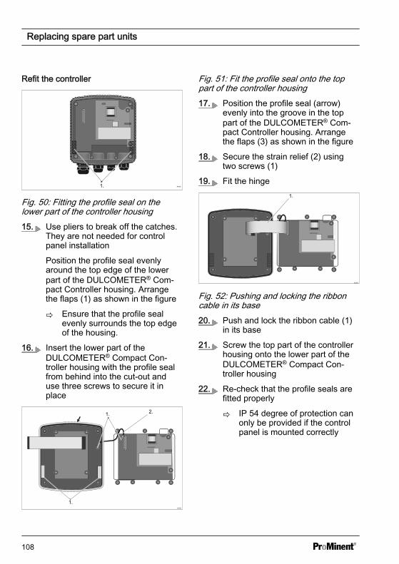
Refit the controller
A03601.
Fig. 50: Fitting the profile seal on thelower part of the controller housing15. Use pliers to break off the catches.
They are not needed for controlpanel installation
Position the profile seal evenlyaround the top edge of the lowerpart of the DULCOMETER® Com‐pact Controller housing. Arrangethe flaps (1) as shown in the figure
ð Ensure that the profile sealevenly surrounds the top edgeof the housing.
16. Insert the lower part of theDULCOMETER® Compact Con‐troller housing with the profile sealfrom behind into the cut-out anduse three screws to secure it inplace
A0351
1.
2.1.
Fig. 51: Fit the profile seal onto the toppart of the controller housing17. Position the profile seal (arrow)
evenly into the groove in the toppart of the DULCOMETER® Com‐pact Controller housing. Arrangethe flaps (3) as shown in the figure
18. Secure the strain relief (2) usingtwo screws (1)
19. Fit the hinge
A0352
1.
Fig. 52: Pushing and locking the ribboncable in its base20. Push and lock the ribbon cable (1)
in its base
21. Screw the top part of the controllerhousing onto the lower part of theDULCOMETER® Compact Con‐troller housing
22. Re-check that the profile seals arefitted properly
ð IP 54 degree of protection canonly be provided if the controlpanel is mounted correctly
Replacing spare part units
108
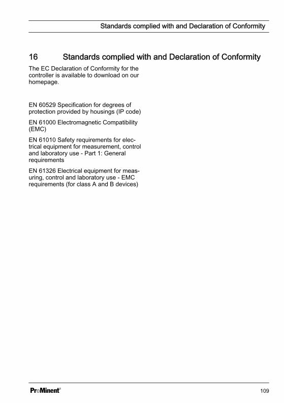
16 Standards complied with and Declaration of ConformityThe EC Declaration of Conformity for thecontroller is available to download on ourhomepage.
EN 60529 Specification for degrees ofprotection provided by housings (IP code)
EN 61000 Electromagnetic Compatibility(EMC)
EN 61010 Safety requirements for elec‐trical equipment for measurement, controland laboratory use - Part 1: Generalrequirements
EN 61326 Electrical equipment for meas‐uring, control and laboratory use - EMCrequirements (for class A and B devices)
Standards complied with and Declaration of Conformity
109
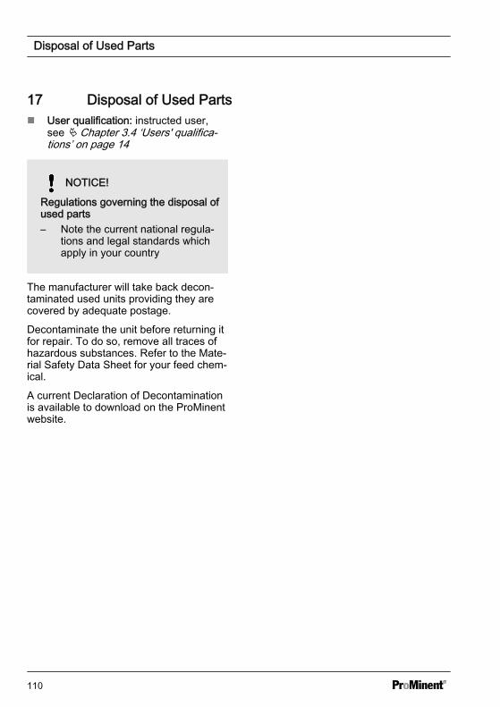
17 Disposal of Used Partsn User qualification: instructed user,
see Ä Chapter 3.4 ‘Users' qualifica‐tions’ on page 14
NOTICE!
Regulations governing the disposal ofused parts– Note the current national regula‐
tions and legal standards whichapply in your country
The manufacturer will take back decon‐taminated used units providing they arecovered by adequate postage.
Decontaminate the unit before returning itfor repair. To do so, remove all traces ofhazardous substances. Refer to the Mate‐rial Safety Data Sheet for your feed chem‐ical.
A current Declaration of Decontaminationis available to download on the ProMinentwebsite.
Disposal of Used Parts
110
18 GlossaryCell constant
The cell constant of a conductive conduc‐tivity sensor is determined by the geom‐etry (surface of the electrodes and theirdistance) of the sensor.
The cell constant can deviate by up to10% from the nominal value specified onthe sensor. The geometry can alsochange through wear and tear or roughattempts at cleaning it.
Calibrating the cell constant generallycompensates for both effects. Films onthe sensors, caused for example by dirt orlime can also change the cell constant.The cell constants are generally changedgradually over a long period of time. In theevent of change, repeated monitoring orcleaning of the sensor is imperative.
Temperature coefficients
If an aqueous solution is heated, itincreases its electrolytic conductivity,although the concentration of,for example, salts has not changed.
The temperature coefficient compensatesmathematically for this temperature influ‐ence on the conductivity so that when thetemperature of the solution is changed,the same display value always appears(Attention: the temperature has to bemeasured).
The temperature measurement of a con‐ductivity sensor is sluggish, so that itneeds a few minutes until the temperatureof the liquid is displayed in a stablemanner. Wait until the value is stable orslightly begins to change in oppositedirections. In the event of rapid tempera‐ture changes, we would recommend anexternal temperature sensor with a fastresponse time.
The conductivity measurement is basedon a reference temperature, which is usu‐ally 25°C. However the conductivity meas‐urement can also be adapted to deviatingreference temperatures. A comparison ofelectrolytic conductivity is also possiblewith temperature changes to to automatictemperature compensation. The tempera‐ture coefficient α is given in %/°C or %/K.With potable water, the temperature coef‐ficient is approximately 2% /°C of the tem‐perature change.
Glossary
111
19 IndexAAccessories . . . . . . . . . . . . . . . . . . 101Action, step by step . . . . . . . . . . . . . . 2Ambient conditions . . . . . . . . . . . . . . 94Assembled sensor cables . . . . . . . . . 40
BBasic functions . . . . . . . . . . . . . . . . 16Bleeding . . . . . . . . . . . . . . . . . . . . . 16Bottom section of the control housing . 25
CCable connection set . . . . . . . . . . . . 19Cable ties . . . . . . . . . . . . . . . . . . . . 21Check strap for strain relief . . . . . . . 102Chemical Resistance . . . . . . . . . . . . 95Configuration . . . . . . . . . . . . . . . . . . 16Contrast setting . . . . . . . . . . . . . . . . 51Control panel cut-out . . . . . . . . . . 23, 25
DDeburr the edges . . . . . . . . . . . . . . . 23Declaration of Conformity . . . . . . . . 109Degree of protection IP 54 . . . . . . 25, 38Degree of protection IP 67 . . . . . . . . 38Dimensions . . . . . . . . . . . . . . . . . . . 94Drill . . . . . . . . . . . . . . . . . . . . . . . . 23Drill holes . . . . . . . . . . . . . . . . . . . . 20Drilling template . . . . . . . . . . . . . . . . 23
EError Logger . . . . . . . . . . . . . . . . . . 88
FFine fuse 5x20 T 0.8 A . . . . . . . . . . 101
GGeneral non-discriminatory approach . . 2General water treatment . . . . . . . . . . 16
HHysteresis . . . . . . . . . . . . . . . . . . . . 64
IIdentity code . . . . . . . . . . . . . . . . . . . 6Incorrect metering . . . . . . . . . . . . . . 43Intended Use . . . . . . . . . . . . . . . . . . 13Interference-prone cables . . . . . . . . . 30
LLarge threaded connection (M 20 x1.5) . . . . . . . . . . . . . . . . . . . . . . . . 38Legend for "Wiring" table . . . . . . . . . . 33Links to elements or sections of theseinstructions or other applicable docu‐ments . . . . . . . . . . . . . . . . . . . . . . . . 2
MMaterial thickness of control panel . . . 22Max. switching current: . . . . . . . . . . 100Max. switching voltage: . . . . . . . . . . 100More symbols . . . . . . . . . . . . . . . . . . 2Mounting (mechanical) . . . . . . . . . . . 19Mounting kit . . . . . . . . . . . . . . . . . . . 22Mounting materials . . . . . . . . . . . . . . 19Mounting position . . . . . . . . . . . . . . . 17
NNoise generation . . . . . . . . . . . . . . . 95Non-discriminatory approach . . . . . . . . 2
OOperating elements . . . . . . . . . . . . . 49Original Prominent cable . . . . . . . . . . 33Overview of equipment . . . . . . . . . . 49
PPipe bracket . . . . . . . . . . . . . . . . . . 20Pipe diameter . . . . . . . . . . . . . . . . . 21plant rooms . . . . . . . . . . . . . . . . . . . 95Preparing the control panel . . . . . . . . 23Profile seal . . . . . . . . . . . . . . . . . . . 25Punch out threaded holes . . . . . . . . . 38
Index
112
QQuestion: Does the control have to beadjusted during commissioning? . . . . 44Question: Does the system have tem‐perature compensation? . . . . . . . . . . 83Question: How are the device andsensor calibrated? . . . . . . . . . . . . . . 55Question: How do I vent the pump, forexample? . . . . . . . . . . . . . . . . . . . . 81Question: How is initial commis‐sioning done? . . . . . . . . . . . . . . . . . 43Question: How should the controllerbe mounted in terms of its reading,mounting and operating position? . . . . 17Question: How should the sensorcable be assembled? . . . . . . . . . . . . 31Question: Is there a legend for the"Wiring" table? . . . . . . . . . . . . . . . . . 33Question: What applications is thecontroller intended for? . . . . . . . . . . . 16Question: What can be calibrated? . . . 55Question: What can the output relaysdo? . . . . . . . . . . . . . . . . . . . . . . . . . 16Question: What control direction isavailable? . . . . . . . . . . . . . . . . . . . . 16Question: What do I have to considerin terms of recycling? . . . . . . . . . . . . 18Question: What do the LEDs indicate? 16Question: What happens in the eventof incorrect calibration? . . . . . . . . . . . 56Question: What information is madeavailable in the continuous display? . . 52Question: What information is madeavailable in the info display? . . . . . . . 53Question: What is the load capacity ofthe hinge? . . . . . . . . . . . . . . . . . . . . 17Question: What needs to be consid‐ered in terms of accessibility? . . . . . . 17Question: When are the actuatorsreset to factory settings? . . . . . . . . . . 44Question: Where can I find the Decla‐ration of Conformity? . . . . . . . . . . . . 109Question: Which cable is connectedto which threaded connector? . . . . . . 32Question: Which measured variablescan be processed? . . . . . . . . . . . . . . 16
Question: Which sensors can I con‐nect to the controller? . . . . . . . . . . . . 40Question: Which standards are com‐plied with? . . . . . . . . . . . . . . . . . . . 109
RReducing inserts . . . . . . . . . . . . . . . 38Replacing spare part units . . . . . . . . 102Replacing the lower part of thehousing (control panel installation) . . 106Replacing the lower part of thehousing (wall/tube retaining bracket) . 104Replacing the top part of the housing 102
SSafety information . . . . . . . . . . . . . . 10Selection of the sensor connected . . . 40Sensor connection . . . . . . . . . . . . . . 40Small threaded connection (M 16 x1.5) . . . . . . . . . . . . . . . . . . . . . . . . 38Snap-hooks . . . . . . . . . . . . . . . . . . . 20Sound Pressure Level . . . . . . . . . . . . 95Spare parts . . . . . . . . . . . . . . . . . . 101Standard scope of delivery . . . . . . . . 19Standards complied with . . . . . . . . . 109Strain relief . . . . . . . . . . . . . . . . 25, 38Strain relief strap . . . . . . . . . . . . . . 101
TTop section of the control housing . . . 25
UUsers' qualifications . . . . . . . . . . . . . 14
VVenting . . . . . . . . . . . . . . . . . . . . . . 81
WWall/pipe bracket . . . . . . . . . . . . . . . 20Washer . . . . . . . . . . . . . . . . . . . . . . 19Weights . . . . . . . . . . . . . . . . . . . . . 94Wiring . . . . . . . . . . . . . . . . . . . . . . . 33Wiring diagram . . . . . . . . . . . . . . . . 37
Index
113

114

115

985092, 3, en_GB
© 2015
ProMinent GmbHIm Schuhmachergewann 5 - 1169123 Heidelberg, GermanyTelephone: +49 6221 842-0Fax: +49 6221 842-419Email: [email protected]: www.prominent.com