ductma te ‘25’/’35’/’45’ - north america's...
TRANSCRIPT
D U C T M A T E
• Simple to install• No additional sealing required
• Available in specialty metals• Consistent connections
Strong and Virtually Leak Free
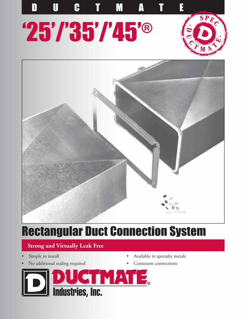
Rectangular Duct Connection System
‘25’/’35’/’45’®

‘25’/’35’/’45’® Rectangular Duct Connection System
D E S C R I P T I O NDuctmate 25/35/45 connection systems consist of roll-formed flanges, corner pieces, gasket and cleat. The flanges attach to the duct wall and have an integral mastic which allows the flange to seal itself to the duct. Corner pieces are used to add rigidity to the flange; hold the ductwork together and provide a sealing surface for the gasket. The gasket serves as a seal between the flanges. The cleat insures even compression of the gasket along the length of the flange.
B A S I C U S EDuctmate 25/35/45 are used to connect rectangular ducts when a rigid, leak-free connection is required.
S P E C I A L C H A R A C T E R I S T I C S• Patented downset in corner insures proper sealing
(excludes Ductmate ‘45’)• Patented corner clips ease installation (excludes Ductmate ‘45’)• Sealing materials meet NFPA 90A & B Class 1 requirements• The Ductmate ‘45’ system is not recommended for applications with
duct gauges heavier than 10 or lighter than 22.• The Ductmate ‘35’ system is not recommended for applications with
duct gauges heavier than 16 GA, or lighter than 26 GA.• The Ductmate ‘25’ is not recommended for applications with duct
gauges heavier than 20 GA or lighter than 26 GA.
T E C H N I C A L I N F O R M A T I O NDuctmate ‘45’ was tested in accordance with SMACNA testing procedures. No external sealant was employed and the test results reveal: the Ductmate ‘45’ system is comparable to a SMACNA Class K transverse joint; the Ductmate ‘35’ system is comparable to the SMACNA Class “J” transverse joint and the Ductmate ‘25’ system is comparable to the SMACNA Class “F” joint. Ductmate ‘35’ in stainless steel exhibits the same performance as galvanized. Aluminum DM35 is comparable to a SMACNA H connection. DM25 is not available in aluminum or stainless. DC35 corner pieces must be used with aluminum. Aluminized or PVC cleats are used with aluminum flanges. Cleat is not available in aluminum. Do not notch the corners when fabricating ductwork for the Ductmate System.
P A C K A G I N G I N F O R M A T I O NThe Ductmate Systems consist of the following components:a. Ductmate ‘45’ flange is roll-formed from 18 GA galvanized steel,
with an integral sealant.b. Ductmate ‘35’ flange is roll-formed from 20 GA galvanized steel,
with an integral sealant.c. Ductmate ‘25’ flange is roll-formed from 24 GA galvanized steel,
with an integral sealant.d. Ductmate ‘45’ electroplated, bolt corner pieces insert into the hollow
web of the ‘45’ angle.e. Ductmate DCIIIA, DCIIIB or DC35 corner pieces insert into the
hollow web of the ‘35’ Angle.f. Ductmate DC25 clip or DC25 bolt corner pieces insert into the
hollow web of the ‘25’ Angle.g. Ductmate ‘45’ metal cleat is roll-formed from 22 GA galvanized steel.h. Metal cleat is roll-formed from 20 GA galvanized steel.
(PVC Cleat is available upon request).i. 440 Butyl Gasket is extruded butyl for use between mating flanges.
(Neoprene gasket is available upon request).j. Corner clips are 16 GA galvanized steel.
(Use of nuts and bolts optional: ⅜” x 1” for DCIIIB, ⅝” x 1” for Ductmate DC25 corners).
C L E A T
I N S T A L L A T I O N I N S T R U C T I O N SDo not notch the corners when fabricating ductwork for the Ductmate System.
Marks deviations from the original instructions when installing Ductmate “45”.
PVC CLEAT:
Polyvinyl chloride (PVC) is an organic polymer derived from petroleum and salt.
Performance Properties:
Relative high ignition resistance: flash ignition 391°/735°F
self ignition 454°C/850°F
Low fuel contribution
Lack of flaming drips
High external heat necessary to maintain combustion
UL94-Passes
UL723 (ASTM E-84) Test Data: Flame Spread:10
Fuel Contribution: 0
Smoke Density: 10
Service Temp: +32°F to +150°F
PVC Cleat is used around perimeter of transverse joint. Not recom-mended for roof top applications.
METAL CLEAT:
DM Metal Cleat is roll-formed of 20 GA galvanized steel for application around perimeter of transverse joint.
Cutting Ductmate Angle1. Always cut Ductmate angle
1¼” ‒ 1⅜” shorter than duct dimension. For DM45, cut 1½” ‒ 1⅝” shorter. Slam the blade through the Angle as quickly as possible. Saw must have sufficient horsepower. Always use a metal friction saw blade. A band saw or hack saw can be substituted.
2. Never cut Ductmate angle with legs up as chips may fall into the mastic.
Never use an abrasive blade to cut Ductmate angle as the heat can melt out the mastic.
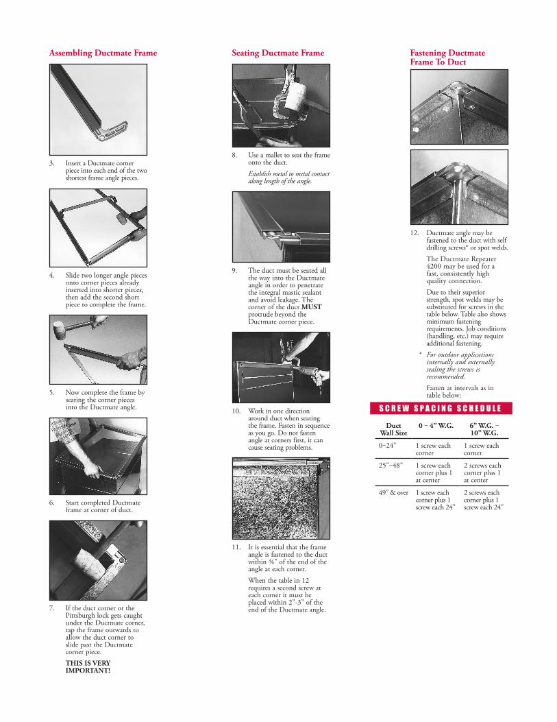
Assembling Ductmate Frame
3. Insert a Ductmate corner piece into each end of the two shortest frame angle pieces.
4. Slide two longer angle pieces onto corner pieces already inserted into shorter pieces, then add the second short piece to complete the frame.
5. Now complete the frame by seating the corner pieces into the Ductmate angle.
6. Start completed Ductmate frame at corner of duct.
7. If the duct corner or the Pittsburgh lock gets caught under the Ductmate corner, tap the frame outwards to allow the duct corner to slide past the Ductmate corner piece.
THIS IS VERY IMPORTANT!
Seating Ductmate Frame
8. Use a mallet to seat the frame onto the duct.
Establish metal to metal contact along length of the angle.
9. The duct must be seated all the way into the Ductmate angle in order to penetrate the integral mastic sealant and avoid leakage. The corner of the duct MUST protrude beyond the Ductmate corner piece.
10. Work in one direction around duct when seating the frame. Fasten in sequence as you go. Do not fasten angle at corners first, it can cause seating problems.
11. It is essential that the frame angle is fastened to the duct within ¾” of the end of the angle at each corner.
When the table in 12 requires a second screw at each corner it must be placed within 2”-3” of the end of the Ductmate angle.
Fastening Ductmate Frame To Duct
Duct Wall Size
0 ‒ 4” W.G. 6” W.G. ‒ 10” W.G.
0‒24” 1 screw each corner
1 screw each corner
25”‒48” 1 screw each corner plus 1 at center
2 screws each corner plus 1 at center
49” & over 1 screw each corner plus 1 screw each 24”
2 screws each corner plus 1 screw each 24”
S C R E W S P A C I N G S C H E D U L E
12. Ductmate angle may be fastened to the duct with self drilling screws* or spot welds.
The Ductmate Repeater 4200 may be used for a fast, consistently high quality connection.
Due to their superior strength, spot welds may be substituted for screws in the table below. Table also shows minimum fastening requirements. Job conditions (handling, etc.) may require additional fastening.
* For outdoor applications internally and externally sealing the screws is recommended.
Fasten at intervals as in table below:

Apply Ductmate 440 Gasket Tape
13. Systems ‘25’ and ‘35’ use ⅝” Ductmate 440 Gasket Tape. Start applying halfway between duct corners. Position in center of Ductmate angle as in photo.
13A. System ‘45’ requires 1” Ductmate 440 Gasket Tape. Start applying halfway between duct corners. Position on inside edge of Ductmate angle as in photo.
14. Position 440 Gasket in an arc so that it covers the three points in the duct corner. Gasket must cover all three points. Some gasket will protrude into the airstream. Press gasket firmly into contact with the raw edge of the duct corner and Ductmate corner assembly. Ductmate 440 is the preferred gasket. Refer to procedures on the back of the brochure for applications using Ductmate Neoprene Gasket.
IMPORTANT: Gasket must cover these 3 points.
15. Apply 440 gasket completely around Ductmate frame to the beginning point. Where gasket meets overlay about ⅜”.
16. On the mating Ductmate frame apply 440 gasket only to the corners as in photo (approximately 3” per corner). The same 3 point application requirements apply as in photo 14.
Note: An optional 3” x 2” corner patch can be used for corners to help eliminate inconsistent or reoccurring gasketing problems. (Is Not Mandatory)
17. Carefully align mating frames before they touch. Ductmate 440 adheres on contact. A drift pin can be used to correct any misalignment.
18. Compress gasket at corners with vice-grip while snapping in corner clips.
Note: Ductmate alignment grips (shown) can be used to simplify assembly.
19. Slide corner clips onto the Ductmate 25/35 joined corner pieces. Tap with hammer until rear tab clicks into notch on corner pieces and locks in for a permanent connection.
Completing The Connection
20. Repeat the process at each corner of duct for a quick, strong, good-looking, permanent, no-leak connection of uniform quality every time.
21. Ductmate 25/35 cleat can be snapped-on with the Cleater I Tool or with the Cleater II where space is restricted.
Ductmate ‘45’ requires the Versa Cleater Tool for installation of the larger Ductmate 45 Snap-On cleat.
Insert cleat into tool, hook onto mated frames near corner (do not attempt to apply onto corner clips), apply pressure to handle so Cleater tool compresses frames and cleat snaps on. Work toward center of duct using the schedule shown below.
For weather-proof duct connection, install a full-length, one-piece cleat to top duct flange joint to prevent water from collecting on gasket.
If a corner cannot be clipped or bolted due to inaccessibility, cleat can be driven onto the mating flanges to complete the Ductmate connection.
With DM440 Gasket For all low, medium and high pressure applications, use 6” cleat, 24” O.C.With Neoprene Gasket For 1/2”-2” WG/SP use 6” cleat, 24” O.C. For 3”-4” WG//SP use 6” cleat, 18” O.C. For 6”-10” WG/SP use 6” cleat, 12” O.C.
Cleat Installation
L I M I T E D P R O D U C T W A R R A N T YDuctmate warrants that 25/35/45®, when properly installed and maintained, will be free from defects in material and workmanship, and will comply with all written specifications made by Ductmate at the time of sale. Ductmate’s warranty shall run for a period of one year from the date of manufacture.
Warranty Limitation The warranty stated above is in lieu of all other warranties, express or implied, including but not limited to the implied warranties of MERCHANTABILITY AND FITNESS FOR A PARTICULAR PURPOSE. Although Ductmate may have suggested the product, or provided written or oral advice to the Purchaser, it is the Purchaser’s responsibility to test and determine the suitability of 25/35/45®, for the intended use and purpose, and Purchaser and/or its customer assumes all risk and liability whatsoever regarding such suitability.
Limitation of Liability In the event of a breach of the above warranty, Ductmate’s sole obligation, and Purchaser’s sole and exclusive remedy, shall be, at Ductmate’s option, repair or replacement of any defective products, or refund of an applicable portion of the purchase price. Ductmate shall have no liability for costs of removal or reinstallation of the product. The Purchaser agrees that no other remedy, including but not limited to loss of profits, loss sales, injury to person or property, or any other special, incidental or consequential damages, shall be available to the Purchaser for any claim arising out of this Agreement, regardless of whether such claim is made in contract or in tort, including strict liability in tort. In no event will Ductmate be obligated to pay damages to the Purchaser in any amount exceeding the purchase price that the Purchaser paid to Ductmate for the allegedly defective product.
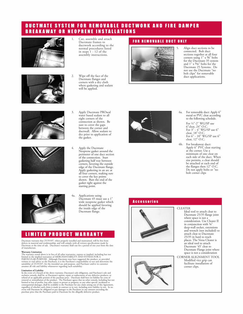
D U C T M A T E S Y S T E M F O R R E M O V A B L E D U C T W O R K A N D F I R E D A M P E R B R E A K A W A Y O R N E O P R E N E I N S T A L L A T I O N S
1. Cut, assemble and attach Ductmate frames to ductwork according to the normal procedures listed in steps 1 - 12 of the assembly instructions.
2. Wipe off the face of the Ductmate flanges and corners with a dry cloth where gasketing and sealant will be applied.
3. Apply Ductmate PROseal water based sealant to all eight corners of the connection as shown. Be sure to cover the gaps between the corner and ductwall. Allow sealant to dry prior to application of the gasket.
4. Apply the Ductmate Neoprene gasket around the perimeter of one duct section of the connection. Start gasketing half way between corners, favoring the outside edge of the Ductmate flange. Apply gasketing in an arc at all four corners, making sure to cover the key points shown. Butt the end of the gasket tight against the starting point.
4a. Applications using Ductmate 45 must use a 1” wide neoprene gasket which should be applied favoring the inside edge of the Ductmate flange.
6a. For removable duct: Apply 6” metal or PVC cleat according to the following schedule.
For ½”-2" WG/SP use 6”cleat, 24” O.C. For 3” - 4” WG/SP use 6” cleat, 18” O.C. For 6” - 10” WG/SP use 6” cleat, 12” O.C.
6b. For breakaway duct: Apply 6” PVC cleat starting at the corner. Use a minimum of one cleat on each side of the duct. When size permits, a cleat should be attached at each end of the flanges then 12” O.C. Do not apply bolts or “no bolt corner clips
5. Align duct sections to be connected. Bolt duct sections together at all four corners using 1” x a” bolts for the Ductmate 35 system and 1” x c” bolts for the Ductmate 25 Systems. Do not use the Ductmate “no bolt clips” for removable duct applications.
F O R R E M O V A B L E D U C T O N L Y
CLEATER Ideal tool to attach cleat to Ductmate 25/35 flange joint where space is not a consideration. Use Cleater II in conjunction with ⅝” deep-wall socket, extensions and wrench (not included) to attach cleat to Ductmate 25/35 in hard to reach places. The Versa Cleater is an ideal tool to attach Ductmate ‘45’ cleat to Ductmate Flange joint where space is not a consideration
CORNER ALIGNMENT TOOL Modified vice grip can facilitate installation of corner clips.
A c c e s s o r i e s

Distributed By:
Ductmate Is A Proud Member Of The Following Organizations:
This spec data is printed on paper that meets the Certified Fiber Sourcing requirements of the SFI program.
10%
®
Charleroi, PA 210 Fifth Street Charleroi, PA 15022 724-258-0500
Lodi, CA810 S. Cluff AvenueLodi, CA 95240-9141209-333-4680
Additional Manufacturing and Warehousing in Monongahela, PA and Wagoner, OK
1-800-245-3188 • www.ductmate.com© Copyright Ductmate Industries, Inc. All rights reserved. 32 - 11/17
Frequently a contractor installing a high velocity duct system will employ a duct joint with which either he or his work force have no experience. In such a case, it is strongly recommended that the contractor promptly test the initial 100 to 300 feet of duct before installing any more duct. This test will quickly reveal whether or not the workmen can make this joint air-tight in an economical manner.
Reprinted from SMACNA High Pressure Manual.
D U C T M A T E ‘ 4 5 ’ C O M P O N E N T SDC45 Corner Piece
Hole for ½” carriage bolt
11 GA galvanized steel
120M
M43/
4 ”
Ductmate “45”Slide-OnCross Section
A D D I T I O N A L C O M P O N E N T SCorner Bolt Sizes (with nuts)
Ductmate 25 c”
35 a”
45 ½”
Corner ClipFor DCIIIB & DJRGA Boltless Corner Application
Press-On Bull NosingDuctmate Flange
Duct Wall
Insulation
Press-On Bull Nosing
D U C T M A T E ‘ 3 5 ’ C O M P O N E N T SDCIIIB Corner Piece
Notch for Corner Clip Hole for optional 3/8” boltFlange for Corner Clip
DC35 Corner PieceHole for ⅜” carriage bolt
Ductmate “35”Slide-OnCross Section
DCIIIA Corner PieceHole for 3/8” carriage bolt
D U C T M A T E ‘ 2 5 ’ C O M P O N E N T SDC25 Corner Piece
Notch for Corner Clip Hole for optional c” bolt
Flange for Corner Clip
Ductmate “25”Slide-OnCross Section
Bolted DC25 Corner PieceHole for c” carriage bolt