‘25’/‘35’/‘45’ ectangular -...
TRANSCRIPT

Strong and Virtually Leak-Free
D U C T M A T E
Industries, Inc.®
• Simple to install• No additional sealing required
• Available in specialty metals• Consistent connections
‘25’/‘35’/‘45’
Rectangular Duct Connection SystemRE
CTAN
GULA
RCO
NNEC
TION
SYS
TEM
S
Visit our on-line information center at www.ductmate.com

D E S C R I P T I O N P R O D U C T G U A R A N T E E
‘25’/‘35’/‘45’ Rectangular DuctConnection System
All component parts of the Ductmate Systems are guaranteed against defectivematerial.
C L E A TPVC CLEAT: Polyvinyl chloride (PVC) is an organic polymer derived from petroleum andsalt.PERFORMANCE PROPERTIES:
Relative high ignition resistance flash ignition 391º/735ºFself ignition 454ºC/850ºF
Low fuel contributionLack of flaming dripsHigh external heat necessary to maintain combustionUL94-PassesUL723 (ASTM E-84) Test Data: Flame Spread:10
Fuel Contribution: 0Smoke Density: 10
Service Temp: +32ºF to +150ºF
PVC Cleat is used around perimeter of transverse joint. Not recommended forroof top applications.
METAL CLEAT: DM Metal Cleat is roll-formed of 20 GA galvanized steel for application aroundperimeter of transverse joint.
P A C K A G I N G I N F O R M A T I O NThe Ductmate Systems consist of the following components:a. Ductmate ‘45’ flange is roll-formed from 18 GA galvanized steel, with an
integral sealant.b. Ductmate ‘35’ flange is roll-formed from 20 GA galvanized steel, with an
integral sealant.c. Ductmate ‘25’ flange is roll-formed from 24 GA galvanized steel, with an
integral sealant.d. Ductmate ‘45’ electroplated, bolt corner pieces insert into the hollow
web of the ‘45’ angle.e. Ductmate DCIIIA, DCIIIB or DC35 corner pieces insert into the hollow
web of the ‘35’ Angle.f. Ductmate DC25 clip or DC25 bolt corner pieces insert into the hollow
web of the ‘25’ Angle.g. Ductmate ‘45’ metal cleat is roll-formed from 22 GA galvanized steel.h. Metal cleat is roll-formed from 20 GA galvanized steel.
(PVC Cleat is available upon request).i. Gasket is extruded butyl for use between mating flanges.
(Neoprene gasket is available upon request).j. Corner clips are 16 GA galvanized steel. (Use of nuts and bolts
optional: 3/8" x 1" for DCIIIB, 5/16" x 1" for Ductmate DC25 corners).
Ductmate 25/35/45 connection systems consist of roll-formed flanges, cornerpieces, gasket and cleat. The flanges attach to the duct wall and have an integralmastic which allows the flange to seal itself to the duct. Corner pieces are usedto add rigidity to the flange; hold the ductwork together and provide a sealingsurface for the gasket. The gasket serves as a seal between the flanges. The cleatinsures even compression of the gasket along the length of the flange.
Ductmate 25/35/45 are used to connect rectangular ducts when a rigid, leak-free connection is required.
B A S I C U S E
Ductmate ‘45’ was tested in accordance with SMACNA testing procedures. Noexternal sealant was employed and the test results reveal: the Ductmate ‘45’system is comparable to a SMACNA Class K transverse joint; the Ductmate ‘35’system is comparable to the SMACNA Class “J” transverse joint and theDuctmate ‘25’ system is comparable to the SMACNA Class “F” joint. Ductmate‘35’ in stainless steel exhibits the same performance as galvanized. AluminumDM35 is comparable to a SMACNA H connection. DM25 is not available inaluminum or stainless. DC35 corner pieces must be used with aluminum.Aluminized or PVC cleats are used with aluminum flanges. Cleat is not availablein aluminum. Do not notch the corners when fabricating ductwork for theDuctmate System.
T E C H N I C A L I N F O R M A T I O N
S P E C I A L C H A R A C T E R I S T I C SPatented downset in corner insures proper sealing (excludes Ductmate ‘45’)Patented corner clips ease installation (excludes Ductmate ‘45’)Sealing materials meet NFPA 90A & B Class 1 requirementsThe Ductmate ‘45’ system is not recommended for applications with ductgauges heavier than 10 or lighter than 22.The Ductmate ‘35’ system is not recommended for applications with ductgauges heavier than 16 GA, or lighter than 26 GA.The Ductmate ‘25’ is not recommended for applications with duct gaugesheavier than 20 GA or lighter than 26 GA.
I N S T A L L A T I O N I N S T R U C T I O N S
1. Always cut Ductmate angle 1 1/4" — 1 3/8" shorter thanduct dimension. Slam the bladethrough the Angle as quickly aspossible. Saw must havesufficient horsepower. Always usea metal friction saw blade. Aband saw or hack saw can besubstituted.
2. Never cut Ductmate angle withlegs up as chips may fall into themastic.
Never use an abrasive blade tocut Ductmate angle as the heatcan melt out the mastic.
CUTTING DUCTMATE ANGLE
Do not notch the corners when fabricating ductwork forthe Ductmate System.* Marks deviations from the original instructions when installing
Ductmate “45”.
3. Insert a Ductmate corner piece into each end of thetwo shortest frame angle pieces.
4. Slide two longer angle pieces onto corner piecesalready inserted into shorter pieces, then add thesecond short piece to complete the frame.
5. Now complete the frame by seating the corner piecesinto the Ductmate angle.
6. Start completed Ductmate frame at corner of duct.
7. If the duct corner or the Pittsburgh lock gets caughtunder the Ductmate corner, tap the frame outwards toallow the duct corner to slide past the Ductmatecorner piece. THIS IS VERY IMPORTANT!
8. Use a mallet to seat the frame onto the duct.Establish metal to metal contact along length ofthe angle.
9. The duct must be seated all the way into the Ductmateangle in order to penetrate the integral mastic sealantand avoid leakage. The corner of the duct MUSTprotrude beyond the Ductmate corner piece.
10. Work in one direction around duct when seatingthe frame. Fasten in sequence as you go. Do notfasten angle at corners first, it can cause seatingproblems.
11. It is essential that the frame angle is fastened to theduct within 3/4" of the end of the angle at eachcorner.
When the table in 12 requires a second screw ateach corner it must be placed within 2"-3" of the endof the Ductmate angle.
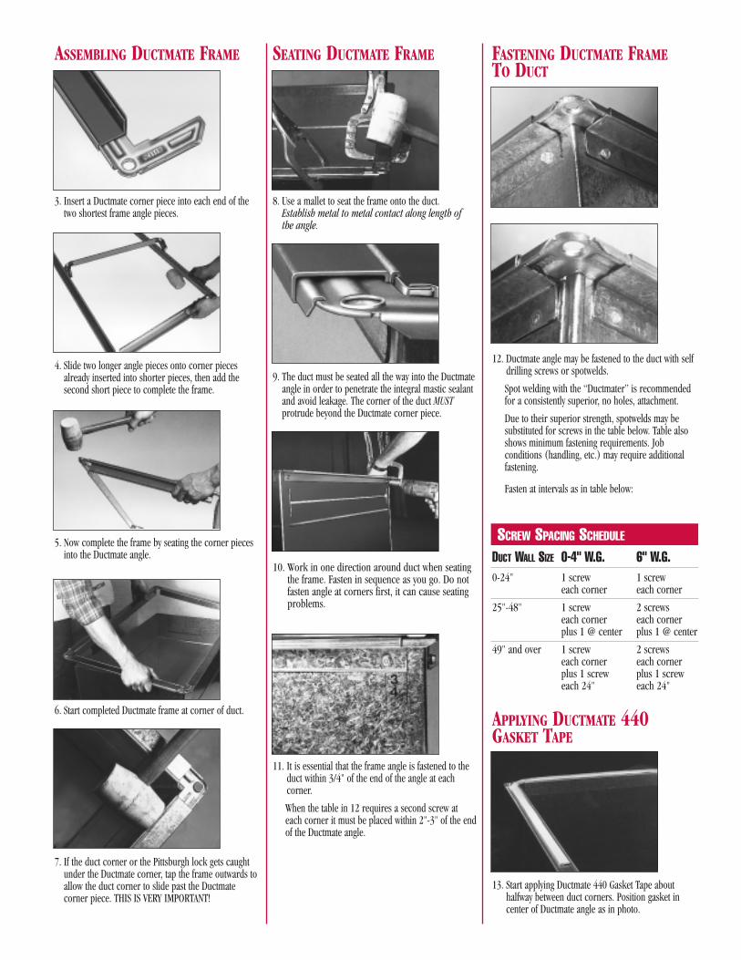
12. Ductmate angle may be fastened to the duct with selfdrilling screws or spotwelds.
Spot welding with the “Ductmater” is recommendedfor a consistently superior, no holes, attachment.
Due to their superior strength, spotwelds may besubstituted for screws in the table below. Table alsoshows minimum fastening requirements. Jobconditions (handling, etc.) may require additionalfastening.
Fasten at intervals as in table below:
ASSEMBLING DUCTMATE FRAME FASTENING DUCTMATE FRAMETO DUCT
SEATING DUCTMATE FRAME
SCREW SPACING SCHEDULE
13. Start applying Ductmate 440 Gasket Tape abouthalfway between duct corners. Position gasket incenter of Ductmate angle as in photo.
APPLYING DUCTMATE 440GASKET TAPE
DUCT WALL SIZE 0-4" W.G. 6" W.G.0-24" 1 screw 1 screw
each corner each corner
25"-48" 1 screw 2 screwseach corner each cornerplus 1 @ center plus 1 @ center
49" and over 1 screw 2 screwseach corner each cornerplus 1 screw plus 1 screweach 24" each 24"

Cut this page 5/8" short so not to interfere w
ith the hole punching.
16. On the mating Ductmate frame apply 440 gasketonly to the corners as in photo (approximately 3"per corner). The same 3 point applicationrequirements apply as in photo 14.
Note: An optional 3" x 2" corner patch can be used forcorners to help eliminate inconsistent or reoccurringgasketing problems. (Is Not Mandatory)
17. Carefully align mating frames before they touch.Ductmate 440 adheres on contact. A drift pin canbe used to correct any misalignment.
18. Compress gasket at corners with vice-grip whilesnapping in corner clips.
NOTE: Ductmate alignment grips (shown) can be used to simplify assembly.
CLEAT INSTALLATION
19. Slide corner clips onto joined corner pieces. Tapwith hammer until rear tab clicks into notch oncorner pieces and locks in for a permanentconnection.
20. Repeat the process at each corner of duct for aquick, strong, good-looking, permanent, no-leakconnection of uniform quality every time.
21. Ductmate 25/35 cleat can be snapped-on with theCleater 1 Tool or with the Cleater II where spaceis restricted.Ductmate ‘45’ requires the Versa Cleater Tool forinstallation of the larger Ductmate 45 Snap-Oncleat.Insert cleat into tool, hook onto mated framesnear corner (do not attempt to apply onto cornerclips), apply pressure to handle so cleater toolcompresses frames and cleat snaps on. Worktoward center of duct using the schedule shownbelow.For weather-proof duct connection, install a full-length, one-piece cleat to top duct flange joint toprevent water from collecting on gasket.If a corner cannot be clipped or bolted due toinaccessibility, cleat can be driven onto the matingflanges to complete the Ductmate connection.
COMPLETING THE CONNECTION
IMPORTANT:Gasket must cover
these 3 points.➝➝➝
WITH DM440 GASKETFor all low, medium and high pressure applications,use 6" cleat, 24" O.C.WITH NEOPRENE GASKETFor 1/2"-2" WG/SP use 6" cleat, 24" O.C.For 3"-4" WG//SP use 6" cleat, 18" O.C.For 6"-10" WG/SP use 6" cleat, 12" O.C.
*13A. Start applying Ductmate 440 1" x 3/16" GasketTape about halfway between duct corners.Position gasket to the inside edge of the Ductmate angle as in photo.
14. Position 440 Gasket in an arc so that it covers thethree points in the duct corner. Gasket mustcover all three points. Some gasket willprotrude into the airstream. Press gasket firmlyinto contact with the raw edge of the duct cornerand Ductmate corner assembly. Ductmate 440 isthe preferred gasket. Refer to procedures on theback of the brochure for applications usingDuctmate Neoprene Gasket.
*19A. Insert a 1/2" nut and bolt into each corner and tighten.
15. Apply 440 gasket completely around Ductmateframe to the beginning point. Where gasket meetsoverlay about 3/8".

Industries, Inc.E. MONONGAHELA, PA1502 Industrial DriveE. Monongahela, PA 15063-9709800-245-3188724-258-0500FAX: 724-258-5494 www.ductmate.com
LODI, CA810 S. Cluff AvenueLodi, CA 95240-3141800-344-3270209-333-4680FAX: 209-333-4678
®
Distributed By:
32/11-02
D U C T M A T E S Y S T E M F O R R E M O V A B L E D U C T W O R K A N D F I R ED A M P E R B R E A K A W A Y O R N E O P R E N E I N S T A L L A T I O N S
1. Cut, assemble and attachDuctmate frames to ductworkaccording to the normalprocedures listed in steps 1 - 12 of the assemblyinstructions.
2. Wipe off the face of theDuctmate flanges and cornerswith a dry cloth where gasketingand sealant will be applied
3. Apply Ductmate PROseal waterbased sealant to all eightcorners of the connection asshown. Be sure to cover thegaps between the corner andductwall. Allow sealant to dryprior to application of thegasket.
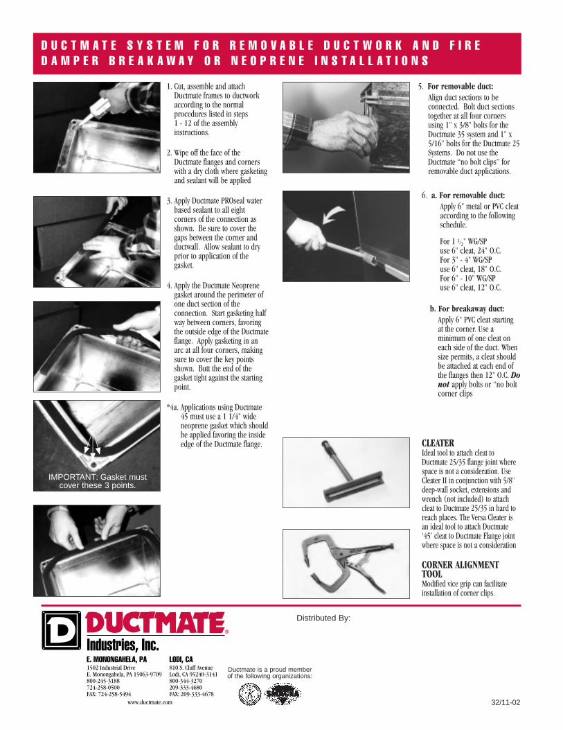
4. Apply the Ductmate Neoprenegasket around the perimeter ofone duct section of theconnection. Start gasketing halfway between corners, favoringthe outside edge of the Ductmateflange. Apply gasketing in anarc at all four corners, makingsure to cover the key pointsshown. Butt the end of thegasket tight against the startingpoint.
*4a. Applications using Ductmate45 must use a 1 1/4" wideneoprene gasket which shouldbe applied favoring the insideedge of the Ductmate flange.
IMPORTANT: Gasket mustcover these 3 points.
➝➝➝
6. a. For removable duct:Apply 6" metal or PVC cleataccording to the followingschedule.
For 1 1/2" WG/SP use 6" cleat, 24" O.C.For 3" - 4" WG/SP use 6" cleat, 18" O.C.For 6" - 10" WG/SP use 6" cleat, 12" O.C.
b. For breakaway duct:Apply 6" PVC cleat startingat the corner. Use aminimum of one cleat oneach side of the duct. Whensize permits, a cleat shouldbe attached at each end ofthe flanges then 12" O.C. Donot apply bolts or “no boltcorner clips
5. For removable duct:Align duct sections to beconnected. Bolt duct sectionstogether at all four cornersusing 1" x 3/8" bolts for theDuctmate 35 system and 1" x5/16" bolts for the Ductmate 25Systems. Do not use theDuctmate “no bolt clips” forremovable duct applications.
CLEATER Ideal tool to attach cleat toDuctmate 25/35 flange joint wherespace is not a consideration. UseCleater II in conjunction with 5/8"deep-wall socket, extensions andwrench (not included) to attachcleat to Ductmate 25/35 in hard toreach places. The Versa Cleater isan ideal tool to attach Ductmate‘45’ cleat to Ductmate Flange jointwhere space is not a consideration
CORNER ALIGNMENTTOOLModified vice grip can facilitateinstallation of corner clips.
Ductmate is a proud member of the following organizations: