ductile iron awwa (cast) fittings - tuvalcatuvalca.com.ve/catalogos/victaulic/pdf/23.05.pdf ·...
TRANSCRIPT

MATERIAL SPECIFICATIONS Fitting: Ductile iron conforming to ASTM A-536, Grade 65-45-12. Ductile iron conforming to ASTM
A-395, grade 65-45-15 is available upon special request.
Fitting Coating: (specify choice*)
• Standard on request:
• Non-coated
• Alkyd-phenol primer
• Bituminous coating
• Optional:
• Coal tar epoxy coating
• Cement/mortar lining – Type II
• Glass Lining
• Other linings available. Contact Victaulic.
* Coatings are applied per manufacturer’s recommended mils.
AWWA FITTINGS
Victaulic fittings for AWWA size pipe are supplied with rigid radius grooves in
accordance with ANSI/AWWA C-606. Fittings conform to ANSI A21.10/AWWA
C-110 for center-to-end dimensions and AWWA C-153 or ANSI A21.10/AWWA C-110
for wall thickness.
While most requirements are specified “black” or non-coated, fittings can be
supplied with an alkyd-phenolic primer, or bituminous coating. Coal tar epoxy and
other coatings are also available. The standard black asphalt coating used on our
cement lined AWWA size fittings is NSF 61 Listed. Cast surfaces will be provided
with surface equivalent to SSPC-SP6 prior to coating unless specified otherwise.
Fittings are available with flanged ends wherever grooved ends are shown.
Linings include cement/mortar Type 2 (standard) and others. Fittings can readily be
prepared for glass lining by others.
Fittings are rated for working pressures to 350 psi/2400 kPa (ductile iron) in
3 – 12"/80 – 300 mm sizes and to 250 psi/1725 kPa (gray iron) in sizes 3 – 12"/80 –
300 mm , and to 250 psi/1725 kPa (ductile iron), or 150 psi/1035 kPa (gray iron)
for 14"/350 mm and larger. Victaulic fittings shown have an end-to-end dimension
tolerance of ±1⁄8" in all sizes and styles.
CAST FITTINGS – TAPPED
Victaulic can supply tapped fittings on order to ANSI B16.1 dimension locations.
Specify fitting size, tap location by letter on order.
BASE FITTINGS
Grooved end base 90° elbows and base tees are available with dimensions to ANSI
B16.1.
23.05_1
Ductile Iron AWWA (Cast) Fittings
23.05AWWA DUCTILE IRON PIPE – GROOVED FITTINGS
JOB/OWNER CONTRACTOR ENGINEER
System No. __________________________ Submitted By ________________________ Spec Sect ____________ Para __________
Location ____________________________ Date ________________________________ Approved ___________________________
Date ________________________________
www.victaulic.com
VICTAULIC IS A REGISTERED TRADEMARK OF VICTAULIC COMPANY. © 2006 VICTAULIC COMPANY. ALL RIGHTS RESERVED. PRINTED IN THE USA.
REV_H

DIMENSIONS
C to E
NO. 100-C
Cto E
C to E
NO. 10-C
C to E
NO. 11-C
C to E
NO. 12-C
C to E
NO. 13-C
SizeNo. 100-C
90º Long Radius ElbowNo. 10-C90º Elbow
No. 11-C45° Elbow
No. 12-C22½° Elbow
No. 13-C11¼° Elbow
NominalSize
Inchesmm
ActualOutside Dia.
Inchesmm
C to EInches
mm
Approx. Weight Each
Lbskg
C to EInches
mm
Approx. Weight Each
Lbs.kg
C to EInches
mm
Approx. Weight Each
Lbs.kg
C to EInches
mm
Approx. Weight Each
Lbs.kg
C to EInches
mm
Approx. Weight Each
Lbs.kg
3 3.960 7.75 19.3 5.50 8.6 3.00 5.8 3.00 12.5 3.00 9.080 100.6 197 8.8 140 3.9 76 2.6 76 5.7 76 4.1
4 4.800 9.00 28.0 6.50 12.0 4.00 8.4 4.00 11.5 4.00 11.5100 121.9 229 12.7 165 5.4 102 3.8 102 5.2 102 5.2
6 6.900 11.50 55.0 8.00 22.0 5.00 15.0 5.00 25.0 5.00 21.5150 175.3 292 25.0 203 10.0 127 6.8 127 11.3 127 9.8
8 9.050 14.00 83.0 9.00 38.0 5.50 28.8 5.50 39.5 5.50 39.0200 229.9 356 37.7 229 17.2 140 13.1 140 17.9 140 17.7
10 11.100 16.50 160.0 11.00 76.0 6.50 43.3 6.50 67.0 6.50 77.0250 281.9 419 72.6 279 34.5 165 19.6 165 30.4 165 34.9
12 13.200 19.00 210.0 12.00 92.0 7.50 72.0 7.50 108.0 7.50 120.0300 335.3 483 95.3 305 41.7 191 32.7 191 49.0 191 54.4
14 15.300 21.50 261.0 14.00 174.0 7.50 104.0 7.50 92.0 7.50 101.0350 388.6 546 118.4 356 78.9 191 47.2 191 41.7 191 45.8
16 17.400 24.00 337.0 15.00 239.0 8.00 142.0 8.00 112.0 8.00 121.0400 442.0 610 152.9 381 108.4 203 64.4 203 50.8 203 54.9
18 19.500 26.50 451.0 16.50 328.0 8.50 186.0 8.50 145.0 8.50 146.0450 495.3 673 204.6 419 148.8 216 84.4 216 65.8 216 66.2
20 21.600 29.00 588.0 18.00 413.0 9.50 246.0 9.50 200.0 9.50 202.0500 548.6 737 266.7 457 187.3 241 111.6 241 90.7 241 91.6
24 25.800 34.00 909.0 22.00 668.0 11.00 414.0 11.00 282.0 11.00 284.0600 655.3 864 412.3 559 303.0 279 187.8 279 127.9 279 128.8
30 32.000 41.50 2136.0 25.00 1002.0 15.00 720.0 15.00 681.0 15.00 699.0750 762.0 1054 968.9 635 454.4 381 326.6 381 308.9 381 317.1
36 38.300 49.00 3120.0 28.00 1608.0 18.00 1152.0 18.00 975.0 18.00 1124.0900 914.4 1245 1415.2 711 729.4 457 522.6 457 442.3 457 509.8
Elbows
NO. 100-C 90º Long Radius Elbow
NO. 10-C 90º Elbow
NO. 11-C 45º Elbow
NO. 12-C 22 ½º Elbow
NO. 13-C 11 ¼º Elbow
23.05_2
Ductile Iron AWWA (Cast) Fittings
23.05AWWA DUCTILE IRON PIPE – GROOVED FITTINGS
www.victaulic.com
VICTAULIC IS A REGISTERED TRADEMARK OF VICTAULIC COMPANY. © 2006 VICTAULIC COMPANY. ALL RIGHTS RESERVED. PRINTED IN THE USA.
REV_H

C to E
CtoE
NO. 20-C
C to LE
C toSE
NO. 33-C
C to E
NO. 35-C
C to LE
C toLE
C toSE
NO. 30-C
T
NO. 60-C
SizeNo. 20-C
TeeNo. 33-CTrue Wye
No. 35-CCross
No. 30-C45° Lateral
No. 60-CCap†
NominalSize
Inchesmm
ActualOutside Dia.
Inchesmm
C to EInches
mm
Approx. Wgt. Each
Lbs.kg
C to LEInches
mm
C to SEInches
mm
Approx. Wgt. Each
Lbs.kg
C to EInches
mm
Approx. Wgt. Each
Lbs.kg
C to LEInches
mm
C to SEInches
mm
Approx. Wgt. Each
Lbs.kg
TThickness
Inches mm
Approx. Wgt. Each
Lbs.kg
3 3.960 5.50 14.2 5.50 3.00 25.00 5.50 24.0 10.00 3.00 28.0 1.22 3.080 100.6 140 6.4 140 76 635 140 10.9 254 76 12.7 31 1.4
4 4.800 6.50 19.0 6.50 3.00 55.0 6.50 40.0 12.00 3.00 38.4 1.16 5.0100 121.9 165 8.6 165 76 25.0 165 18.1 305 76 12.7 29 2.3
6 6.900 8.00 34.0 8.00 3.50 90.0 8.00 71.0 14.50 3.50 67.0 1.16 9.0150 175.3 203 15.4 203 89 40.8 203 32.2 368 89 30.4 29 4.1
8 9.050 9.00 59.0 9.00 4.50 140.0 9.00 106.0 17.50 4.50 120.0 1.34 16.0200 229.9 229 26.8 229 114 63.5 229 48.1 445 114 54.4 34 7.3
10 11.100 11.00 111.0 11.00 5.00 220.0 11.00 225.0 20.50 5.00 215.0 1.53 37.2250 281.9 279 50.4 279 127 99.8 279 102.1 521 127 97.5 39 16.9
12 13.200 12.00 136.0 12.00 5.50 315.0 12.00 310.0 24.50 5.50 346.0 1.53 52.0300 335.3 305 61.7 305 140 142.9 305 140.6 622 140 157.0 39 23.6
14 15.300 14.00 262.0 14.00 6.00+
14.00 307.0 27.00 6.00 492.0 2.75* 55.0350 388.6 356 118.8 356 152 356 139.3 686 152 223.2 70 25.0
16 17.400 15.00 304.0 15.00 6.50+
15.00 426.0 30.00 6.50 696.0 2.75* 68.0400 442.0 381 137.9 381 165 381 193.2 762 165 315.7 70 30.9
18 19.500 16.50 408.0 16.50 7.00+
16.50 567.0 32.00 7.00 870.0 2.75* 90.0450 495.3 419 185.1 419 178 419 254.9 813 178 394.6 70 40.8
20 21.600 18.00 552.0 18.00 8.00+
18.00 717.0 35.00 8.00 1103.0 2.75* 110.0500 548.6 457 250.4 457 203 457 325.2 889 203 500.3 70 50.0
24 25.800 22.00 980.0 22.00 9.00+
22.00 1177.0 40.50 9.00 1746.0 2.75* 165.0600 655.3 559 444.5 559 229 559 533.9 1029 229 792.0 70 74.8
30 32.000 25.00 1552.0 25.00 10.00+
25.00 1366.0 49.00 10.00 3280.0 4.00* 300.0750 762.0 635 704.0 635 254 635 619.6 1245 254 1487.8 102 136.1
36 38.300 28.00 2050.0 28.00 15.00+
28.00 1885.0 56.00 15.25 5020.0 4.00* 536.0900 914.4 711 929.9 711 381 711 855.0 1422 387 2277.1 102 243.1
* Dish caps. + Contact Victaulic for details.
† Caps from ½ – 3"/15 – 80 mm tap sizes.
Tee, True Wye, Cross, Lateral, and Cap
NO. 20-C Tee
NO. 33-C True Wye
NO. 35-C Cross
NO. 30-C 45º Lateral
NO. 60-C Cap
Size Dimensions – Inches/mmApprox.
Weight Each
Nominal Size
Inchesmm C to EOR C to EOB
Lbs. kg
4×
4×
6 + +
47.0100 100 150 21.3
6×
6×
8 8.00 8.00 79.0150 150 200 203 203 35.8
8×
8×
10 11.00 11.00 164.0200 200 250 279 279 74.4
10×
10×
12+ +
226.0250 250 300 102.5
+ Contact Victaulic for details.
Bullhead Tee
NO. 21-C
C toEOB
C toEOR
NO. 21-C
23.05_3
Ductile Iron AWWA (Cast) Fittings
23.05AWWA DUCTILE IRON PIPE – GROOVED FITTINGS
www.victaulic.com
VICTAULIC IS A REGISTERED TRADEMARK OF VICTAULIC COMPANY. © 2006 VICTAULIC COMPANY. ALL RIGHTS RESERVED. PRINTED IN THE USA.
REV_H

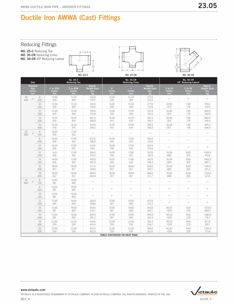
C to E
CtoE
NO. 25-C
J
J
HH
NO. 35-CR
C to LE
C toLE
C toSE
NO. 30-CR
SizeNo. 25-C
Reducing TeeNo. 35-CR
Reducing CrossNo. 30-CR
45° Reducing Lateral
Nominal Size
Inchesmm
C to EORInches
mm
C to EOBInches
mm
Approx. Weight Each
Lbs.kg
HInches
mm
JInches
mm
Approx. Weight Each
Lbs.kg
C to LEInches
mm
C to SEInches
mm
Approx. Weight Each
Lbs.kg
4×
3 6.50 6.50 26.4 6.50 6.50 22.0 12.00 3.00 45.0100 80 165 165 12.0 165 165 10.0 305 76 20.4
6×
3 8.00 8.00 30.0 8.00 8.00 46.0 14.50 3.50 74.0150 80 203 203 13.6 203 203 20.9 368 89 33.6
4 8.00 8.00 34.0 8.00 8.00 38.0 14.50 3.50 80.0100 203 203 15.4 203 203 17.2 368 89 36.3
8×
3 9.00 9.00+ — — — — — —
200 80 229 229
4 9.00 9.00 78.0 9.00 9.00 76.0 17.50 4.50 125.0100 229 229 35.4 229 229 34.5 445 114 56.7
6 9.00 9.00 80.0 9.00 9.00 59.0 17.50 4.50 140.0150 229 229 36.3 229 229 26.8 445 114 63.5
10×
4 11.00 11.00 120.0 11.00 11.00 120.0 20.50 5.00 204.0250 100 279 279 54.4 279 279 54.4 521 127 92.5
6 11.00 11.00 128.0 11.00 11.00 114.0 20.50 5.00 212.0150 279 279 58.1 279 279 51.7 521 127 96.2
8 11.00 11.00 130.0 11.00 11.00 123.0 20.50 5.00 236.0200 279 279 59.0 279 279 56.8 521 127 107.1
12×
4 12.00 12.00 112.0 12.00 12.00 174.0 24.50 5.50 290.0300 100 305 305 50.8 305 305 78.9 622 140 131.5
6 12.00 12.00 180.0 12.00 12.00 130.0 24.50 5.50 302.0150 305 305 81.7 305 305 59.0 622 140 137.0
8 12.00 12.00 186.0 12.00 12.00 139.0 24.50 5.50 324.0200 305 305 84.4 305 305 63.1 622 140 147.0
10 12.00 12.00 192.0 12.00 12.00 154.0 24.50 5.50 356.0250 305 305 87.1 305 305 69.9 622 140 161.5
14×
6 14.00 14.00 238.0 14.00 14.00 215.0 27.00 6.00 330.0350 150 356 356 108.0 356 356 97.5 686 152 149.7
8 14.00 14.00 241.0 14.00 14.00 221.0 27.00 6.00 346.0200 356 356 109.3 356 356 100.3 686 152 156.9
10 14.00 14.00 258.0 14.00 14.00 235.0 27.00 6.00 540.0250 356 356 114.8 356 356 106.6 686 152 244.9
12 14.00 14.00 267.0 14.00 14.00 244.0 27.00 6.00 625.0300 356 356 121.1 356 356 110.7 686 152 283.5
16×
6 15.00 15.00 288.0 15.00 15.00 266.0 30.00 6.50 570.0400 150 381 381 130.6 381 381 120.7 762 165 258.6
8 15.00 15.00 315.0 15.00 15.00 276.0 30.00 6.50 585.0200 381 381 142.9 381 381 125.2 762 165 265.4
10 15.00 15.00 319.0 15.00 15.00 291.0 30.00 6.50 630.0250 381 381 144.7 381 381 132.0 762 165 285.8
12 15.00 15.00 330.0 15.00 15.00 305.0 30.00 6.50 650.0300 381 381 149.7 381 381 138.4 762 165 294.8
14 15.00 15.00 341.0 15.00 15.00 280.0 30.00 6.50 692.0350 381 381 154.7 381 381 127.0 762 165 313.9
TABLE CONTINUED ON NEXT PAGE
Reducing Fittings
NO. 25-C Reducing Tee
NO. 35-CR Reducing Cross
NO. 30-CR 45º Reducing Lateral
23.05_4
Ductile Iron AWWA (Cast) Fittings
23.05AWWA DUCTILE IRON PIPE – GROOVED FITTINGS
www.victaulic.com
VICTAULIC IS A REGISTERED TRADEMARK OF VICTAULIC COMPANY. © 2006 VICTAULIC COMPANY. ALL RIGHTS RESERVED. PRINTED IN THE USA.
REV_H
C to E
CtoE
NO. 25-C
J
J
HH
NO. 35-CR
C to LE
C toLE
C toSE
NO. 30-CR
SizeNo. 25-C
Reducing TeeNo. 35-CR
Reducing CrossNo. 30-CR
45° Reducing Lateral
Nominal Size
Inchesmm
C to EORInches
mm
C to EOBInches
mm
Approx. Weight Each
Lbs.kg
HInches
mm
JInches
mm
Approx. Weight Each
Lbs.kg
C to LEInches
mm
C to SEInches
mm
Approx. Weight Each
Lbs.kg
18×
8 13.00 15.50 326.0 13.00 15.50 272.0+ + +
450 200 330 394 147.9 330 394 123.4
10 13.00 15.50 332.0 13.00 15.50 277.0 32.00 7.00 765.0250 330 394 150.6 330 394 125.6 813 178 347.0
12 13.00 15.50 339.0 13.00 15.50 291.0 32.00 7.00 800.0300 330 394 153.8 330 394 132.0 813 178 362.9
14 16.50 16.50 441.0 16.50 16.50 361.0 32.00 7.00 865.0350 419 419 200.0 419 419 163.7 813 178 392.4
16 16.50 16.50 453.0 16.50 16.50 367.0 32.00 7.00 895.0400 419 419 205.5 419 419 166.5 813 178 406.0
20×
6 14.00 17.00+ — — — — — —
500 150 356 432
8 14.00 17.00 412.0 14.00 17.00 343.0— — —
200 356 432 186.9 356 432 155.6
10 14.00 17.00 419.0 14.00 17.00 343.0+ + +
250 356 432 190.1 356 432 155.6
12 14.0 17.00 426.0 14.00 17.00 357.0 35.00 8.00 1000.0300 356 432 193.2 356 432 161.9 889 203 453.6
14 14.00 17.00 443.0 14.00 17.00 327.0 35.00 8.00 1062.0350 356 432 201.0 356 432 148.3 889 203 481.7
16 18.00 18.00 571.0 18.00 18.00 458.0 35.00 8.00 1105.0400 457 457 259.0 457 457 207.7 889 203 501.2
18 18.00 18.00 584.0 18.00 18.00 469.0 35.00 8.00 1150.0450 457 457 264.9 457 457 212.7 889 203 521.6
24×
6 15.00 19.00+ — — — — — —
600 150 381 483
8 15.00 19.00+ + + + + + +
200 381 483
10 15.00 19.00+ + + + + + +
250 381 483
12 15.00 19.00 593.0 15.00 19.00 475.0+ + +
300 381 483 269.0 381 483 215.5
14 15.00 19.00 610.0 15.00 19.00 450.0 40.50 9.00 1510.0350 381 483 276.7 381 483 204.1 1029 229 684.9
16 15.00 19.00 620.0 15.00 19.00 446.0 40.50 9.00 1580.0400 381 483 281.2 381 483 202.3 1029 229 716.7
18 22.00 22.00 918.0 22.00 22.00 782.0 40.50 9.00 871.0450 559 559 416.4 559 559 354.7 1029 229 395.1
20 22.00 22.00 937.0 22.00 22.00 788.0 40.50 9.00 1705.0500 559 559 425.0 559 559 357.4 1029 229 773.4
TABLE CONTINUED ON NEXT PAGE
Reducing Fittings
NO. 25-C Reducing Tee
NO. 35-CR Reducing Cross
NO. 30-CR 45º Reducing Lateral
23.05_5
Ductile Iron AWWA (Cast) Fittings
23.05AWWA DUCTILE IRON PIPE – GROOVED FITTINGS
www.victaulic.com
VICTAULIC IS A REGISTERED TRADEMARK OF VICTAULIC COMPANY. © 2006 VICTAULIC COMPANY. ALL RIGHTS RESERVED. PRINTED IN THE USA.
REV_H
C to E
CtoE
NO. 25-C
J
J
HH
NO. 35-CR
C to LE
C toLE
C toSE
NO. 30-CR
SizeNo. 25-C
Reducing TeeNo. 35-CR
Reducing CrossNo. 30-CR
45° Reducing Lateral
Nominal Size
Inchesmm
C to EORInches
mm
C to EOBInches
mm
Approx. Weight Each
Lbs.kg
HInches
mm
JInches
mm
Approx. Weight Each
Lbs.kg
C to LEInches
mm
C to SEInches
mm
Approx. Weight Each
Lbs.kg
30 ×
6 18.00 23.00+
18.00 23.00— — — —
750 150 457 584 457 584
8 18.00 23.00+
18.00 23.00+ + + +
200 457 584 457 584
10 18.00 23.00+
18.00 23.00+ + + +
250 457 584 457 584
12 18.00 23.00 1175.0 18.00 23.00 888.0 49.00 10.00 2178.0300 457 584 533.0 457 584 402.8 1245 254 987.9
14 18.00 23.00 1250.0 18.00 23.00 853.0 49.00 10.00 2208.0350 457 584 567.0 457 584 386.9 1245 254 1001.5
16 18.00 23.00 1437.0 18.00 23.00 843.0 49.00 10.00 2248.0400 457 584 651.0 457 584 382.4 1245 254 1019.7
18 18.00 23.00 1450.0 18.00 23.00 839.0 49.00 10.00 2294.0450 457 584 657.7 457 584 380.6 1245 254 1040.6
20 18.00 23.00 1462.0 18.00 23.00 835.0 49.00 10.00 2339.0500 457 584 663.2 457 584 378.8 1245 254 1061.0
24 25.00 25.00 1475.0 25.00 25.00 1304.0 49.00 10.00 2451.0600 635 635 669.1 635 635 591.5 1245 254 1111.8
36×
8 20.00 26.0+
20.00 26.00+ + + +
900 200 508 660 508 660
10 20.00 26.00+
20.00 26.00+ + + +
250 508 660 508 660
12 20.00 26.00+
20.00 26.00 1262.0+ + +
300 508 660 508 660 572.4
14 20.00 26.00+
20.00 26.00 1222.0 54.00 15.25+
350 508 660 508 660 554.3 1372 387
16 20.00 26.00+
20.00 26.00 1213.0 54.00 15.25 3493.0400 508 660 508 660 550.2 1372 387 1584.4
18 20.00 26.00+
20.00 26.00 1204.0 54.00 15.25 3533.0450 508 660 508 660 546.1 1372 387 1602.6
20 20.00 26.00+
20.00 26.00 1190.0 54.00 15.25 3574.0500 508 660 508 660 539.8 1372 387 1621.2
24 20.00 26.00+
20.00 26.00 1163.0 54.00 15.25 3675.0600 508 660 508 660 527.5 1372 387 1667.0
30 28.00 28.00+
28.00 28.00 1865.0 56.00 15.25 3879.0750 711 711 711 711 846.0 1422 387 1759.5
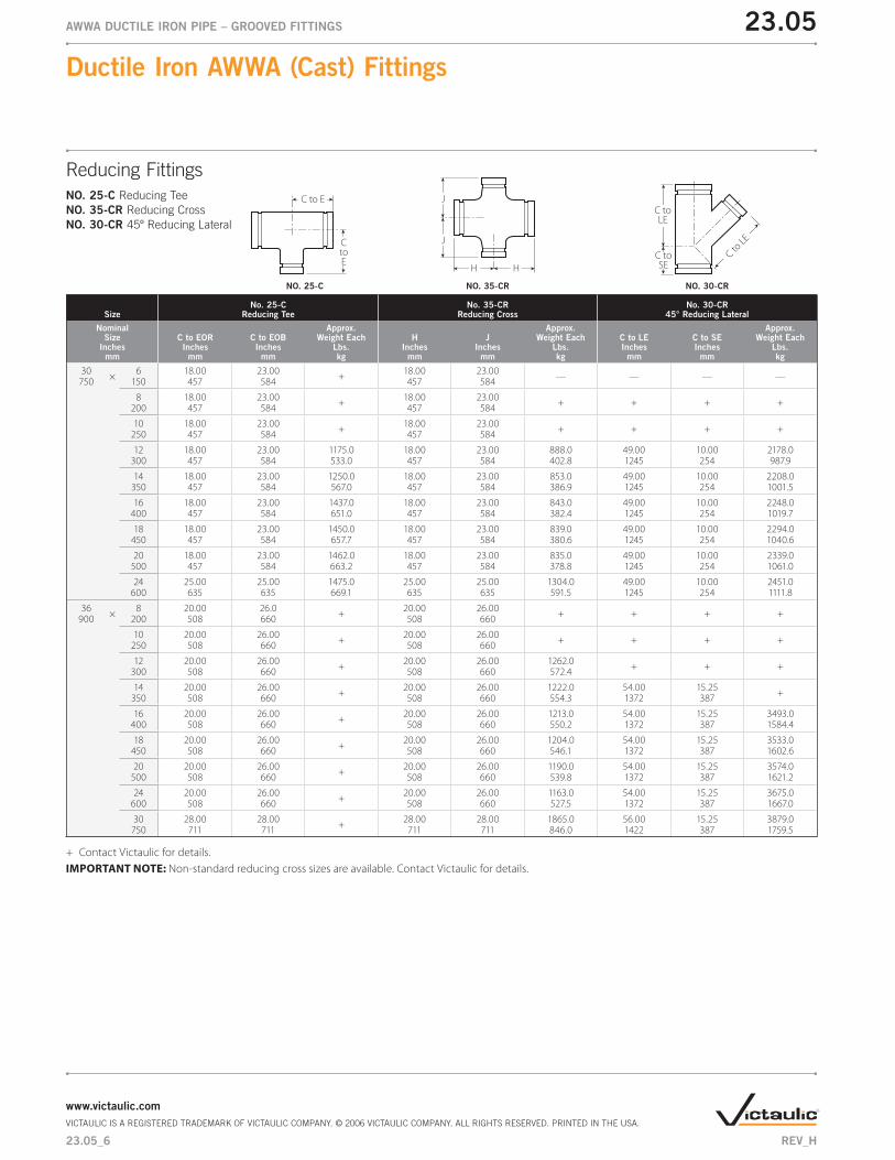
+ Contact Victaulic for details.
IMPORTANT NOTE: Non-standard reducing cross sizes are available. Contact Victaulic for details.
Reducing Fittings
NO. 25-C Reducing Tee
NO. 35-CR Reducing Cross
NO. 30-CR 45º Reducing Lateral
23.05_6
Ductile Iron AWWA (Cast) Fittings
23.05AWWA DUCTILE IRON PIPE – GROOVED FITTINGS
www.victaulic.com
VICTAULIC IS A REGISTERED TRADEMARK OF VICTAULIC COMPANY. © 2006 VICTAULIC COMPANY. ALL RIGHTS RESERVED. PRINTED IN THE USA.
REV_H

E to E
NO. 50-C
E to E
NO. 51-C
C to E
NO. 10-CR
C to E
NO. 100-CR
SizeNo. 50-C
Concentric ReducerNo. 51-C
Eccentric ReducerNo. 10-CR
90° Reducing ElbowNo. 100-CR
90° Long Radius Red. El.
Nominal Size
Inchesmm
E to EInches
mm
Approx. Weight Each
Lbs.kg
E to EInches
mm
Approx. Weight Each
Lbs.kg
C to EInches
mm
Approx.Weight Each
Lbs.kg
C to EInches
mm
Approx. Weight Each
Lbs.kg
4×
3 7.00 10.0 7.00 12.0 6.50 17.0 9.00 20.0100 80 178 4.5 178 5.4 165 7.7 229 8.1
6×
3 9.00 15.0 9.00 20.0 8.00 28.5 11.50 36.0150 80 229 6.8 229 9.1 203 12.9 292 16.3
4 9.00 16.5 9.00 25.0 8.00 29.6 11.50 40.0100 229 7.5 229 11.3 203 13.4 292 18.1
8×
3 11.00 33.0 11.00+ — — — —
200 80 279 15.0 279
4 11.00 28.0 11.00 35.0 9.00 46.5 14.00 60.0100 279 12.7 279 15.9 229 21.1 356 27.2
6 11.00 34.0 11.00 44.0 9.00 48.5 14.00 71.0150 279 15.4 279 20.0 229 22.0 356 32.2
10×
4 12.00 42.0 12.00 54.0 11.00 68.0 16.50 90.0250 100 305 19.1 305 24.5 279 30.8 419 40.8
6 12.00 46.0 12.00 60.0 11.00 77.0 16.50 106.0150 305 20.9 305 27.2 279 34.9 419 48.1
8 12.00 50.0 12.00 70.0 11.00 88.0 16.50 121.0200 305 22.7 305 31.8 279 39.9 419 54.9
12×
4 14.00 60.0 14.00 82.0 12.00+ + +
300 100 356 27.2 356 37.2 305
6 14.00 70.0 14.00 84.0 12.00 110.0 19.00 143.0150 356 31.8 356 38.1 305 49.9 483 64.9
8 14.00 74.0 14.00 91.0 12.00 126.0 19.00 163.0200 356 33.6 356 41.3 305 57.2 483 73.9
10 14.00 84.0 14.00 110.0 12.00 150.0 19.00 188.0250 356 38.1 356 49.9 305 68.0 483 85.3
14×
6 16.00 89.0 16.00 104.0 14.00+ + +
350 150 406 40.4 406 47.2 356
8 16.00 102.0 16.00 121.0 14.00 135.0 21.50 183.0200 406 46.3 406 54.9 356 61.2 546 83.0
10 16.00 112.0 16.00 135.0 14.00 170.0 21.50 213.0250 406 50.8 406 61.2 356 77.1 546 96.6
12 16.00 126.0 16.00 150.0 14.00 195.0 21.50 240.0300 406 57.4 406 68.0 356 88.5 546 108.9
16×
6 18.00 11.0 18.00 140.0— — + +
400 150 457 49.9 457 63.5
8 18.00 122.0 18.00 160.0 15.00+
24.00 228.0200 457 55.3 457 72.6 381 610 103.4
10 18.00 135.0 18.00 168.0 15.00 195.0 24.00 263.0250 457 61.2 457 76.2 381 88.5 610 119.3
12 18.00 146.0 18.00 190.0 15.00 240.0 24.00 295.0300 457 66.2 457 86.2 381 108.9 610 133.8
14 18.00 173.0 18.00 210.0 15.00 280.0 24.00 290.0350 457 78.5 457 95.3 381 127.0 610 131.5
TABLE CONTINUED ON NEXT PAGE
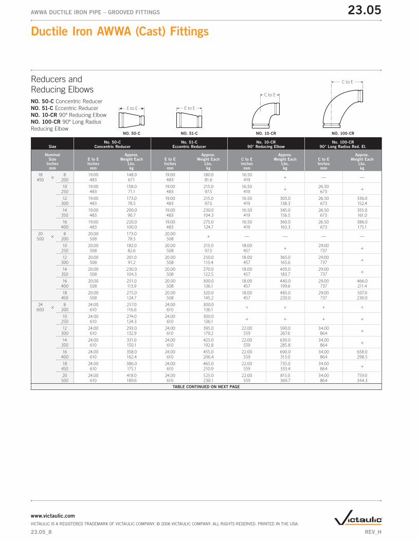
Reducers and Reducing Elbows
NO. 50-C Concentric Reducer
NO. 51-C Eccentric Reducer
NO. 10-CR 90º Reducing Elbow
NO. 100-CR 90º Long Radius
Reducing Elbow
23.05_7
Ductile Iron AWWA (Cast) Fittings
23.05AWWA DUCTILE IRON PIPE – GROOVED FITTINGS
www.victaulic.com
VICTAULIC IS A REGISTERED TRADEMARK OF VICTAULIC COMPANY. © 2006 VICTAULIC COMPANY. ALL RIGHTS RESERVED. PRINTED IN THE USA.
REV_H
E to E
NO. 50-C
E to E
NO. 51-C
C to E
NO. 10-CR
C to E
NO. 100-CR
SizeNo. 50-C
Concentric ReducerNo. 51-C
Eccentric ReducerNo. 10-CR
90° Reducing ElbowNo. 100-CR
90° Long Radius Red. El.
Nominal Size
Inchesmm
E to EInches
mm
Approx. Weight Each
Lbs.kg
E to EInches
mm
Approx. Weight Each
Lbs.kg
C to EInches
mm
Approx.Weight Each
Lbs.kg
C to EInches
mm
Approx. Weight Each
Lbs.kg
18×
8 19.00 148.0 19.00 180.0 16.50+ — —
450 200 483 67.1 483 81.6 419
10 19.00 158.0 19.00 215.0 16.50+
26.50+
250 483 71.1 483 97.5 419 673
12 19.00 173.0 19.00 215.0 16.50 305.0 26.50 336.0300 483 78.5 483 97.5 419 138.3 673 152.4
14 19.00 200.0 19.00 230.0 16.50 345.0 26.50 355.0350 483 90.7 483 104.3 419 156.5 673 161.0
16 19.00 220.0 19.00 275.0 16.50 360.0 26.50 386.0400 483 100.0 483 124.7 419 163.3 673 175.1
20 ×
8 20.00 173.0 20.00+ — — — —
500 200 508 78.5 508
10 20.00 182.0 20.00 215.0 18.00+
29.00+
250 508 82.6 508 97.5 457 737
12 20.00 201.0 20.00 250.0 18.00 365.0 29.00+
300 508 91.2 508 113.4 457 165.6 737
14 20.00 230.0 20.00 270.0 18.00 405.0 29.00+
350 508 104.3 508 122.5 457 183.7 737
16 20.00 251.0 20.00 300.0 18.00 440.0 29.00 466.0400 508 113.9 508 136.1 457 199.6 737 211.4
18 20.00 275.0 20.00 320.0 18.00 485.0 29.00 507.0450 508 124.7 508 145.2 457 220.0 737 230.0
24×
8 24.00 257.0 24.00 300.0+ + + +
600 200 610 116.6 610 136.1
10 24.00 274.0 24.00 300.0+ + + +
250 610 124.3 610 136.1
12 24.00 293.0 24.00 395.0 22.00 590.0 34.00+
300 610 132.9 610 179.2 559 267.6 864
14 24.00 331.0 24.00 425.0 22.00 630.0 34.00+
350 610 150.1 610 192.8 559 285.8 864
16 24.00 358.0 24.00 455.0 22.00 690.0 34.00 658.0400 610 162.4 610 206.4 559 313.0 864 298.5
18 24.00 386.0 24.00 465.0 22.00 735.0 34.00+
450 610 175.1 610 210.9 559 333.4 864
20 24.00 418.0 24.00 525.0 22.00 815.0 34.00 759.0500 610 189.6 610 238.1 559 369.7 864 344.3
TABLE CONTINUED ON NEXT PAGE
Reducers and Reducing Elbows
NO. 50-C Concentric Reducer
NO. 51-C Eccentric Reducer
NO. 10-CR 90º Reducing Elbow
NO. 100-CR 90º Long Radius
Reducing Elbow
23.05_8
Ductile Iron AWWA (Cast) Fittings
23.05AWWA DUCTILE IRON PIPE – GROOVED FITTINGS
www.victaulic.com
VICTAULIC IS A REGISTERED TRADEMARK OF VICTAULIC COMPANY. © 2006 VICTAULIC COMPANY. ALL RIGHTS RESERVED. PRINTED IN THE USA.
REV_H

E to E
NO. 50-C
E to E
NO. 51-C
C to E
NO. 10-CR
C to E
NO. 100-CR
SizeNo. 50-C
Concentric ReducerNo. 51-C
Eccentric ReducerNo. 10-CR
90° Reducing ElbowNo. 100-CR
90° Long Radius Red. El.
Nominal Size
Inchesmm
E to EInches
mm
Approx. Weight Each
Lbs.kg
E to EInches
mm
Approx. Weight Each
Lbs.kg
C to EInches
mm
Approx.Weight Each
Lbs.kg
C to EInches
mm
Approx. Weight Each
Lbs.kg
30×
8+ + + + + + — —
750 200
10+ + + + + + — —
250
12 30.00+
30.00+ + + — —
300 762 762
14 30.00+
30.00+
25.00+ — —
350 762 762 635.0
16 30.00+
30.00+
25.00+
41.50+
400 762 762 635.0 1054
18 30.00+
30.00+
25.00+
41.50+
450 762 762 635.0 1054
20 30.00+
30.00+
25.00+
41.50+
500 762 762 635.0 1054
24 30.00+
30.00+
25.00 1170.0 41.50+
600 762 762 635.0 530.7 1054
36×
8+ + + + + + — —
900 200
10+ + + + + + — —
250
12+ + + + + + — —
300
14 36.00+
36.00+ + + — —
350 914 914
16 36.00+
36.00+ + + — —
400 914 914
18 36.00+
36.00+ + + — —
450 914 914
20 36.00 1280.0 36.00+ + +
49.00+
500 914 580.6 914 1245
24 36.00 1370.0 36.00+ + +
49.00+
600 914 621.4 914 1245
30 36.00 1450.0 36.00+ + +
49.00+
750 914 657.7 914 1245
+ Contact Victaulic for details.
IMPORTANT NOTE:
For 30"/750 mm sizes and larger contact Victaulic for details.
Reducers and Reducing Elbows
NO. 50-C Concentric Reducer
NO. 51-C Eccentric Reducer
NO. 10-CR 90º Reducing Elbow
NO. 100-CR 90º Long Radius
Reducing Elbow
23.05_9
Ductile Iron AWWA (Cast) Fittings
23.05AWWA DUCTILE IRON PIPE – GROOVED FITTINGS
www.victaulic.com
VICTAULIC IS A REGISTERED TRADEMARK OF VICTAULIC COMPANY. © 2006 VICTAULIC COMPANY. ALL RIGHTS RESERVED. PRINTED IN THE USA.
REV_H
S
R
T
U
C toE
C toE
NO. 10-CB
ST
RU
C toE
C to E
NO. 20-CB
STU
R
CtoE
C to E
NO. 25-CB
STU
R
CtoE
C to E
NO. 100-CB
S
W
ROUND BASE
Size Dimensions – Inches/mmApprox.
Weight Each
Nominal Size
Inchesmm
ActualOutside Dia.
Inchesmm
C toE R U T S W
No. 10-CBBase Elbow
Lbs.kg
No. 20-CBBase Tee
Lbs.kg
No. 100-CBLR Base Elbow
Lbs.kg
No. 25-CBRed. Base Tee
Lbs.kg
3 3.960 5.50 4.88 0.50 0.56 5.00 3.88 19.0 19.0— +
80 100.6 140 124 13 14 127 99 8.6 8.6
4 4.800 6.50 5.50 0.50 0.62 6.00 4.75 23.6 26.0— +
100 121.9 165 140 13 16 152 121 10.7 11.8
6 6.900 8.00 7.00 0.62 0.69 7.00 5.50 42.0 50.0— +
150 175.3 203 178 16 18 178 140 19.1 22.7
8 9.050 9.00 8.38 0.88 0.94 9.00 7.50 75.0 92.0— +
200 229.9 229 213 22 24 229 191 34.0 41.7
10 11.100 11.00 9.75 0.88 0.94 9.00 7.50 114.0 125.0— +
250 281.9 274 248 22 24 229 191 51.7 56.7
12 13.200 12.00 11.25 1.00 1.00 11.00 9.50 152.0 183.0— +
300 335.3 305 286 25 25 279 241 69.0 83.0
14 15.300 21.50 12.50 1.00 1.00 11.00 9.50— —
340.0+
350 388.6 546 318 25 25 279 241 154.2
16 17.400 24.00 13.75 1.00 1.00 11.00 9.50— —
425.0+
400 442.0 610 349 25 25 279 241 192.8
18 19.500 26.50 15.00 1.12 1.12 13.50 11.75— —
591.0+
450 495.3 673 381 29 29 343 299 268.1
20 21.600 29.00 16.00 1.12 1.12 13.50 11.75— —
717.0+
500 548.6 737 406 29 29 343 299 325.2
24 25.800 34.00 18.50 1.12 1.12 13.50 11.75— —
1056.0+
600 655.3 864 470 29 29 343 299 479.0
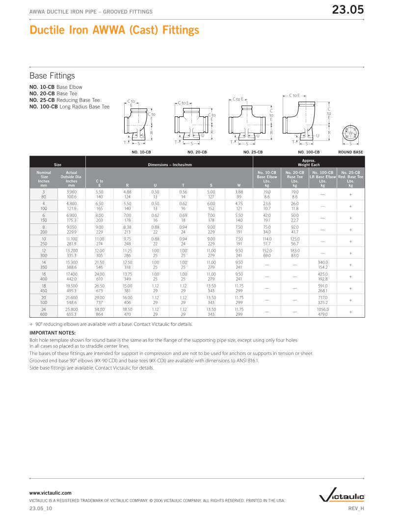
+ 90° reducing elbows are available with a base. Contact Victaulic for details.
IMPORTANT NOTES:
Bolt hole template shown for round base is the same as for the flange of the supporting pipe size, except using only four holes in all cases so placed as to straddle center lines.
The bases of these fittings are intended for support in compression and are not to be used for anchors or supports in tension or sheer.
Grooved end base 90° elbows (#X-90 CDI) and base tees (#X-CDI) are available with dimensions to ANSI B16.1.
Side base fittings are available. Contact Victaulic for details.
Base Fittings
NO. 10-CB Base Elbow
NO. 20-CB Base Tee
NO. 25-CB Reducing Base Tee
NO. 100-CB Long Radius Base Tee
23.05_10
Ductile Iron AWWA (Cast) Fittings
23.05AWWA DUCTILE IRON PIPE – GROOVED FITTINGS
www.victaulic.com
VICTAULIC IS A REGISTERED TRADEMARK OF VICTAULIC COMPANY. © 2006 VICTAULIC COMPANY. ALL RIGHTS RESERVED. PRINTED IN THE USA.
REV_H
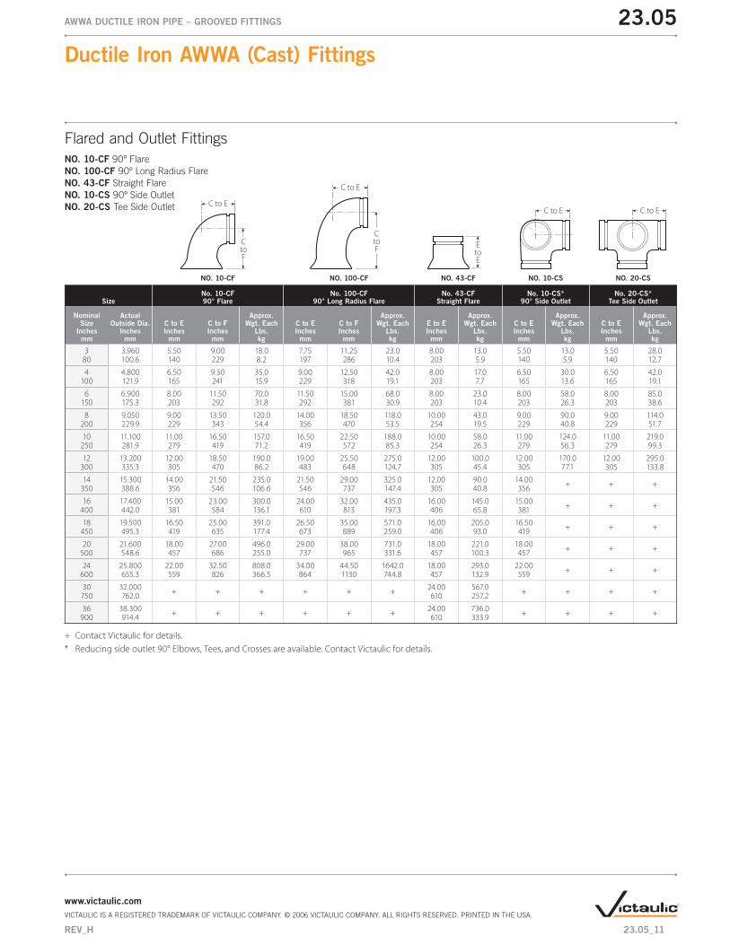
C to E
CtoF
NO. 10-CF
C to E
CtoF
NO. 100-CF
EtoE
NO. 43-CF
C to E
NO. 10-CS
C to E
NO. 20-CS
SizeNo. 10-CF90° Flare
No. 100-CF90° Long Radius Flare
No. 43-CFStraight Flare
No. 10-CS*90° Side Outlet
No. 20-CS*Tee Side Outlet
NominalSize
Inchesmm
ActualOutside Dia.
Inchesmm
C to EInches
mm
C to FInches
mm
Approx. Wgt. Each
Lbs.kg
C to EInches
mm
C to FInches
mm
Approx. Wgt. Each
Lbs.kg
E to EInches
mm
Approx. Wgt. Each
Lbs.kg
C to EInches
mm
Approx. Wgt. Each
Lbs.kg
C to EInches
mm
Approx. Wgt. Each
Lbs.kg
3 3.960 5.50 9.00 18.0 7.75 11.25 23.0 8.00 13.0 5.50 13.0 5.50 28.080 100.6 140 229 8.2 197 286 10.4 203 5.9 140 5.9 140 12.7
4 4.800 6.50 9.50 35.0 9.00 12.50 42.0 8.00 17.0 6.50 30.0 6.50 42.0100 121.9 165 241 15.9 229 318 19.1 203 7.7 165 13.6 165 19.1
6 6.900 8.00 11.50 70.0 11.50 15.00 68.0 8.00 23.0 8.00 58.0 8.00 85.0150 175.3 203 292 31.8 292 381 30.9 203 10.4 203 26.3 203 38.6
8 9.050 9.00 13.50 120.0 14.00 18.50 118.0 10.00 43.0 9.00 90.0 9.00 114.0200 229.9 229 343 54.4 356 470 53.5 254 19.5 229 40.8 229 51.7
10 11.100 11.00 16.50 157.0 16.50 22.50 188.0 10.00 58.0 11.00 124.0 11.00 219.0250 281.9 279 419 71.2 419 572 85.3 254 26.3 279 56.3 279 99.3
12 13.200 12.00 18.50 190.0 19.00 25.50 275.0 12.00 100.0 12.00 170.0 12.00 295.0300 335.3 305 470 86.2 483 648 124.7 305 45.4 305 77.1 305 133.8
14 15.300 14.00 21.50 235.0 21.50 29.00 325.0 12.00 90.0 14.00+ + +
350 388.6 356 546 106.6 546 737 147.4 305 40.8 356
16 17.400 15.00 23.00 300.0 24.00 32.00 435.0 16.00 145.0 15.00+ + +
400 442.0 381 584 136.1 610 813 197.3 406 65.8 381
18 19.500 16.50 25.00 391.0 26.50 35.00 571.0 16.00 205.0 16.50+ + +
450 495.3 419 635 177.4 673 889 259.0 406 93.0 419
20 21.600 18.00 27.00 496.0 29.00 38.00 731.0 18.00 221.0 18.00+ + +
500 548.6 457 686 255.0 737 965 331.6 457 100.3 457
24 25.800 22.00 32.50 808.0 34.00 44.50 1642.0 18.00 293.0 22.00+ + +
600 655.3 559 826 366.5 864 1130 744.8 457 132.9 559
30 32.000+ + + + + +
24.00 567.0+ + + +
750 762.0 610 257.2
36 38.300+ + + + + +
24.00 736.0+ + + +
900 914.4 610 333.9
+ Contact Victaulic for details.
* Reducing side outlet 90° Elbows, Tees, and Crosses are available. Contact Victaulic for details.
Flared and Outlet Fittings
NO. 10-CF 90º Flare
NO. 100-CF 90º Long Radius Flare
NO. 43-CF Straight Flare
NO. 10-CS 90º Side Outlet
NO. 20-CS Tee Side Outlet
23.05_11
Ductile Iron AWWA (Cast) Fittings
23.05AWWA DUCTILE IRON PIPE – GROOVED FITTINGS
www.victaulic.com
VICTAULIC IS A REGISTERED TRADEMARK OF VICTAULIC COMPANY. © 2006 VICTAULIC COMPANY. ALL RIGHTS RESERVED. PRINTED IN THE USA.
REV_H
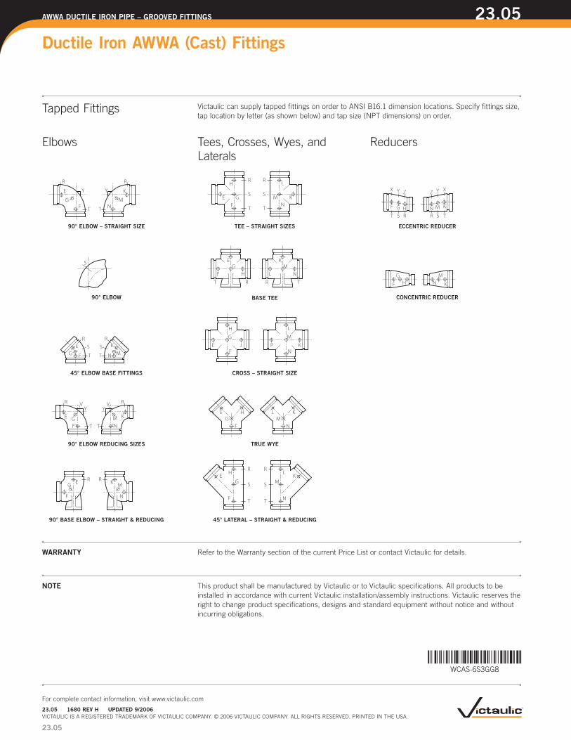
WARRANTY Refer to the Warranty section of the current Price List or contact Victaulic for details.
This product shall be manufactured by Victaulic or to Victaulic specifications. All products to be
installed in accordance with current Victaulic installation/assembly instructions. Victaulic reserves the
right to change product specifications, designs and standard equipment without notice and without
incurring obligations.
NOTE
KL
M
N
R
S
T
EH
G
F
R
S
T
Y
M
K
NT
R
Y
G
E
F T
R
EG
F
R K M
N
R
R
S
T
L
MN
K
R
S
T
H
EF
G
VY
T
R
KMN
VY
T
R
E GF
S
HG
FJE
L
M
NKP
X Y Z
T S R
F G H
Z Y X
R S TN M K
MN
KR
S
TG F
ER
S
T
EG
HFT R
KM
NLR T F H
G
KNM
E HG
F
L KM
N
Tapped Fittings
45° LATERAL – STRAIGHT & REDUCING
90° ELBOW – STRAIGHT SIZE
90° BASE ELBOW – STRAIGHT & REDUCING
TEE – STRAIGHT SIZES
90° ELBOW REDUCING SIZES
90° ELBOW
CROSS – STRAIGHT SIZE
ECCENTRIC REDUCER
45° ELBOW BASE FITTINGS
BASE TEE CONCENTRIC REDUCER
TRUE WYE
Elbows Tees, Crosses, Wyes, and Laterals
Reducers
Victaulic can supply tapped fittings on order to ANSI B16.1 dimension locations. Specify fittings size,
tap location by letter (as shown below) and tap size (NPT dimensions) on order.
23.05
Ductile Iron AWWA (Cast) Fittings
23.05AWWA DUCTILE IRON PIPE – GROOVED FITTINGS
WCAS-6S3GG8
For complete contact information, visit www.victaulic.com
23.05 1680 REV H UPDATED 9/2006
VICTAULIC IS A REGISTERED TRADEMARK OF VICTAULIC COMPANY. © 2006 VICTAULIC COMPANY. ALL RIGHTS RESERVED. PRINTED IN THE USA.