dualframe 75mm casement windows - arcura · sapa building system dualframe 75mm casement windows...
TRANSCRIPT

EPICC421+D11+D13:X46
CI/SfB
UniclassL3811+L411+L413:P43
August 2009
Xh4(21.4)+(31.4)+(31.5)
Sapa Building System
Dualframe 75mm Casement WindowsTechnical Data Sheet

Design featuresPerformance dataSupport servicesProfile inertia valuesGeneral arrangementsJamb/Flat VentCurtain Wall Jamb/Flat VentJamb/Vent - Mullion/VentFixed Light Jamb - Mullion Vent/VentHead VentTransom Vent - Subcill/VentSubcill/Fixed Light/Square Bead - Drainage Tray/Fixed Light/Square BeadConcealed Frame to Frame Coupler - Lightweight Concealed Frame to Frame CouplerFrame to Frame Expansion CouplerHeavy Duty Coupling Box Mullion150º Baypole - 135º Baypole90º External Corner Post90º Internal Corner PostVariable Baypole 162º-175º - Variable Baypole 133º-163ºVariable Baypole 115º-134ºVariable Corner Post 90º-180ºExtended Square Outerframe and Chamfered VentExtended Softline Outerframe and Softline VentChamfered Mullion/TransomSoftline Vent Frame - Heavy Duty Softline Vent FrameWide Square Mullion/Transom with Vent - Wide Softline Mullion/Transom with Softline VentWide Square Transom with Drip - Wide Softline Transom with DripWide Square Transom with Drip Vent/Vent -Wide Softline Transom with Drip Vent/Vent 120mm MidrailFrame Extender/Trickle Vent - Extended Softline Outerframe/Trickle Vent24mm, 28mm and 32mm Glazing Bead Options Internal Glaze Vent - Internal Glaze Dummy VentReverse Rebate Adaptor55mm to 75mm Coupler
3467
101112131415161718
192021222324252627
282930
3132
333435363738
DualframeContents2

ProductDualframe 75mm outward openingside and top hung casementwindows
Design VariantsCan be constructed to form fixedand opening lights either ascombination frames or asseparate coupled lights.
CompatibilityCan also be integrated with otherproducts from the Dualframerange and with Sapa Elegance 52curtain walling.
ApplicationSuitable for installation in newbuild or replacement projects inresidential, commercial or publicbuildings.
FinishesA wide range of polyester powdercoat finishes is available to BS EN12206:1 2004. Anodised finishesare to BS 3987 Grade AA25 etchsilver with a range of specialanodised finishes on application.
For more details, or to talk to aProject Consultant, contact theMarketing Department on 01684853500.
DesignThe Dualframe range 3
BS 4873Licence No. KM74159FM01154
BS 7950Licence No. KM74141
PAS 23-1 andPAS 24-1
Licence No. KM90215
Contemporary Design: The new Sapa Dualframe range signifies a new era in aluminium fenestration, with products that have been specifical designed to comply with the ever increasing complexity Building Regulations, British Standards and other regulatory demands.
Superior thermal performance: Dualframe comfortably exceeds therequirements of Part L 2006 of the Building Regulations (2006) for both thermal insulation and air permeability, and has been designed to be compliant with future anticipated changes. Where required, Dualframe 75 casement can achieve an ‘A’ Window Energy Rating.
Dual colour capability: All Dualframe products can have differing finishes internally and externally.
Integrated design: The Dualframe suite consists of casement, pivot, tilt/turn, sliding and reversible windows, single and double leaf doors and glazed roofing, all of which can be combined to form composite units.
Unique polyamide thermal barrier: With integral bead retention leg to minimise projection of opening lights (patent applied for).
Accreditation: Dualframe casement and tilt/turn windows have been awarded BSI Kitemarks to BS4873 ‘Specification for aluminium alloy windows’ and BS7950 ‘Specification for enhanced security performance of casement and tilt/turn windows for domestic applications’.
Dualframe doors have been awarded BSI PAS023-1 : 1999, ‘Generalperformance requirements for door assemblies; Part 1 - single leaf door assemblies to dwellings’ and PAS024-1 : 1999 ‘enhanced security performance requirements for door assemblies; Part 1 - single leaf external door assemblies to dwellings’.
Dualframe casement, tilt/turn windows and Dualframe doors meet the Secured by Design specification.
Dualframe 75 casement can achieve an ‘A’ Window Energy Rating (WER) where required.
Choice of appearance: Chamfered and Softline profiles are available to many products within the Dualframe suite, options of internal or external beading (including BS7950 compliant security) are also available.
Ease of maintenance: The integration of a ‘Eurogroove’ features enables use of industry standard hardware, available from a variety of sources so that the product is competitive and easily maintained.

Composition and ManufactureAluminium profiles are extruded fromaluminium alloy 6063 or 6060 T6 complyingwith the recommendations of BS EN 755-9:2001. Weatherstripping is polypropylene backedwoven pile and polyurethane foam enclosed ina polythene sheath, set in undercut grooves inthe sash.The thermal barrier section is achieved usingtwo separate aluminium extrusions and twopolyamide extrusions mechanically jointed toform a single compound profile. (Except onsome coupling mullions where a ‘pour and cut’polyurethane resin thermal break is used).Frame members are mitre cut at 45 degrees.Corners are reinforced with stainless steelcorner ties and extruded aluminium cornercleats. All joints are sealed against water entryduring fabrication.
Weather PerformanceWhen tested in accordance with BS 6375:Part 1, all products listed in this data sheet,when manufactured, installed and glazedstrictly to the details outlined in the ProductManual, will exceed exposure category ‘2400Special’.Water Tightness 600 Pascals(static test)Air Permeability 600 PascalsWind Resistance 2400 Pascals** Exposure category varies with Width/Heightof window and mullion/transom used, as theseare the only unsupported members. Anaccurate figure can be obtained using BS 6399: Part 2 calculations and the inertiavalues given in the Product Manual.
AuthorityBS 4873: Aluminium alloy windowsBS 6375-1: Performance of windows:Classification for weathertightness andguidance on selection and specification.BS 6375-2: Performance of windows.Specification for operation and strengthcharacteristics.BS 7950: Specification for enhanced securityperformance of casement and tilt/turn windowsfor domestic applications. BS 6262: Code of practice for glazing forbuildings.BS EN 755-9: Aluminium and aluminiumalloys. Extruded rod/bar, tube and profiles.Profiles, tolerances on dimension and form.BS 3987: Specification for anodic oxidecoatings on wrought aluminium for externalarchitectural applications.
BS EN 12206:1 2004: Specification for powderorganic coatings for application and stoving toaluminium alloy extrusions, sheet andperforated sections for external architecturalpurposes.BS EN 10077-2: Thermal performance ofwindows, doors and shutters – Calculation ofthermal transmittance – Part 2: Numericalmethod for frames.outerframe.
PerformancePerformance data: 75mm Casement
Size LimitationsStandard Casement - Side HungStay Size 8” 12” 16” Butt HingeMax Width 400 600 700 700Max Height 1200 1300 1300 1300Max Weight 18kg 22kg 24kg *Min Width 302 358 601 *Min Height 424** 424** 424** 424**
Standard Casement - Top HungStay Size 6” 8” 10” 12” 16” 20” 24” Butt HingeMax Width 1200 1200 1200 1200 1200 1200 1200 1200Max Height 300 350 400 550 750 1000 1200 1200Max Weight 10kg 12kg 16kg 20kg 21kg 24kg 35kg *Min Width 424** 424** 424** 424** 424** 424** 424** 424**Min Height 250 301 351 401 551 751 1001 *
Heavy Duty Casement - Side HungStay Size 10” 16” Butt HingeMax Width 660 838 838Max Height 1524 1829 1829Max Weight 37kg 45kg *Min Width 302 661 *Min Height 424** 424** 424**
Heavy Duty Casement - Top HungStay Size 10” 12” 16” 22” Butt HingeMax Width 1600 1600 1600 1600 1600*Max Height 635 787 1090 1500 1500Max Weight 38kg 47kg 55kg 75kg *Min Width 424** 424** 424** 424** 424**Min Height 302 636 788 1091 *
All sizes given are in millimetres, all maximum sizes relate to the overall size of the vent frame and not theouterframe.*See Page 5 Hardware and Security** MInimum sizes can be reduced to 302mm when using Cockspur handles.
4

5
Hardware and SecurityThe Dualframe casement window is availableas standard with a multi-point locking system,comprising rods moving in opposingdirections, with opposing centre cam and endshootbolts operated by “autolock” handles withkey deadlocking. Hinges as standard are stainless steel,projecting friction stays with optional restrictedand egress variants.Extruded aluminium butt hinges with stainlesssteel pins are available as an option.Optional Vector Excluder hinge protectorsmust be used when enhanced security toBS7950 is required.The Dualframe casement window system (inboth externally and internally beaded formats),has been tested to BS7950 and BS 4873 incertain configurations, details upon request.*Butt Hinges - Each hinge will carry amaximum of 20Kg in both side hung and tophung applications. Where a top hung vent ishung from a transom, this figure should bereduced to 15Kg per hinge and the maximumwidth of the vent restricted to 1500mm.These butt hinges are primarily designed foruse with folding openers, remote operatinggear or electronic actuators. Where they arefitted in conjunction with espag gear orcockspur handles, suitable friction restrictorsmust also be used.Note that a weatherbar must always be fittedover butt hinge opening lights, unless there isa soffit or similar to give protection. ThereforeDF300 outerframe cannot be used where asoffit does not exist because the weatherbarcannot be fitted.Other hardware specifications are available(eg for remote operation, trickle ventilators),consult Sapa Building Systems Ltd fordetails.
GlazingDrainage in accordance with details listed inthe Product Manual meets the requirements of‘Ventilated and Drained Glazing System’, asspecified in BS6262 for thickness and type.Insulating glass units of 24mm up to 32mmcan be accommodated as standard, otherdepths can be accommodated on request.Fixed/Opening Lights: Glass set againstextruded synthetic rubber gaskets retained inundercut grooves within an aluminium beadprofile. Final retention of the glass is achievedby the application of a co-extruded PVCu/synthetic rubber wedge gasket between theinner face of the glass and the frame.
Thermal PerformanceDualframe 75mm can meet and surpass thearea weighted average U values stipulated inPart L of the Building Regulations. Lower U-values can be achieved using double glazedunits with enhanced thermal insulation, suchas ‘soft coat’ low emissivity glass, argon gasfilling and thermally broken spacer bars. An ‘A’ Window Energy Rating (WER) can beachieved where required.
Site WorkFabrication, installation and glazing service isavailable through a nationwide network offabricators & installers. For details of suitablefabricators & installers, please contact ourMarketing Department on 01684 853500.
BS 4873Licence No. KM74159
BS 7950Licence No. KM74141

Sapa GroupSapa Building Systems Limited isa member of the worldwide SapaGroup. We develop and markethigh value-added profiles inaluminium and are the leadingindependent producer ofaluminium profiles in the world,with customers in Europe, NorthAmerica and Asia. In the UK, theSapa Group has extensive multi-site extruding, re-melt, anodisingand polyester powder coatingfacilities, offering total control anda fast and co-operative response.
Backed by the resources of theGroup, Sapa Building SystemsLimited offers architects andspecifiers a wide range ofinnovative aluminium systems forcurtain walling, doors, windowsand specialist applications. With awealth of European knowledgeand experience our companyincorporates the highly respectedGlostal, Monarch and RC Systembrands that have satisfied thedemands of specifiers for overfour decades. Our companysystems have been approvedunder BS EN ISO 9001:2000 andwe have been recognised as anInvestor in People for over threeyears.
Our field based Project Consultants, working with our in-houseContracts Design and Administration team, provide UK specifiers withspecialist advice concerning the correct application of products, givingguidance on Building Regulations, British Standards and other issuessuch as product specifications, usage, maintenance and safety.Complementary to this, our Product Support Department has aninvaluable reservoir of experience on every aspect of our product range.
We also appreciate that the specification process is influenced by clientdemands to obtain best value, and to that end, we can participate in sitevisits, your design meetings and budgetary planning. We can assist withwritten specification documents (which can be supplied in either an NBSformat, or your own specification layout) and supported by samples,literature and drawings for consultation or planning issues.
Taking this partnership approach through the whole project allows on-site monitoring of manufacturing and installation ensuring thespecifier always has professional support from a worldwide group.Drawing on one of the largest fabricator and installer networks in theUK, we can provide details of specialist contractors who will quote ortender competitively for any type of contract.
For specification assistance or details of fabricators and installers,please call our Marketing Department on 01684 853500.
SupportSupport services6

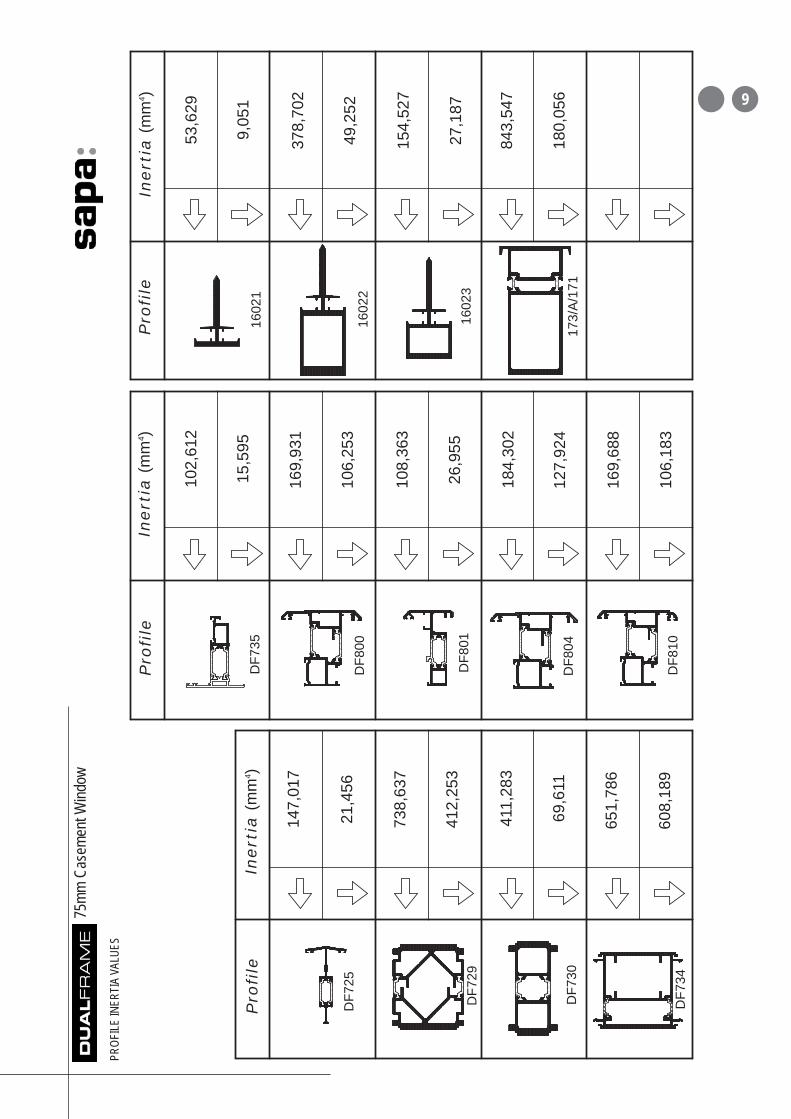
The
follo
win
g pa
ges
give
info
rmat
ion
on th
ein
ertia
val
ues
of th
e in
terg
ral m
ullio
ns,
trans
oms,
bay
pole
s an
d co
uplin
g m
ullio
ns.
BS
639
9 P
art 2
mus
t be
used
to c
alcu
late
the
iner
tia v
alue
requ
ired.
Pro
file
Ine
rtia
(m
m4 )
Pro
file
Ine
rtia
(mm
4 )
Pro
file
Ine
rtia
(m
m4 )
DF1
22
DF1
31
DF1
38
DF1
39
DF1
63(x
2)
DF3
04
DF3
05
DF3
10
DF3
09
DF3
24
161,
075
2,93
0
659,
240
639,
861
338,
423
115,
967
283,
774
55,0
80
228,
932
129,
348
178,
544
27,2
26
55,8
43
6,24
8
222,
833
67,1
30
227,
945
70,3
07
183,
507
47,6
03
111,
371
17,4
07
144,
952
25,9
48
138,
640
36,0
62
DF3
25
DF3
26
DF2
69
DF3
27
175,
923
49,6
18
775
mm C
asem
ent W
indow
PROF
ILEIN
ERTI
AVA
LUES

Pro
file
Ine
rtia
(m
m4 )
Pro
file
Ine
rtia
(m
m4 )
Pro
file
Ine
rtia
(m
m4 )
DF3
31
DF3
33
DF3
35
DF3
44
DF3
46
DF3
52
DF3
51
DF4
10
144,
814
36,2
92
145,
670
36,7
15
176,
027
61,5
67
193,
769
72,0
09
155,
242
54,7
57
209,
575
55,0
90
342,
537
105,
544
176,
722
61,9
75
308,
535
456,
318
220,
050
9,29
8
167,
251
245,
123
DF7
11
384,
692
63,5
78D
F714
DF7
23
DF3
42
DF3
48
256,
423
72,3
40
DF7
24
162,
597
101,
164
75mm
Cas
emen
t Wind
ow
PROF
ILEIN
ERTI
AVA
LUES
8
75mm
Cas
emen
t Wind
ow
PROF
ILEIN
ERTI
AVA
LUES
9
Pro
file
Ine
rtia
(m
m4 )
Pro
file
Ine
rtia
(m
m4 )
Pro
file
Ine
rtia
(m
m4 )
DF7
25
DF7
29D
F801
DF8
04D
F730
DF7
34
1602
2
1602
1
1602
3
173/
A/1
71
147,
017
21,4
56
738,
637
412,
253
DF8
00
169,
931
106,
253
DF7
35
102,
612
15,5
95
108,
363
26,9
55
184,
302
127,
924
411,
283
69,6
11
169,
688
106,
183
651,
786
608,
189
378,
702
49,2
52
53,6
29
9,05
1
154,
527
27,1
87
DF8
10
843,
547
180,
056

Thes
e dr
awing
s illu
strate
a n
umbe
r of t
he a
vaila
ble p
rofile
comb
inatio
ns. O
ther c
ombin
ation
s are
ava
ilable
plea
seco
nsult
Sap
a Bu
ilding
Sys
tems f
or fu
rther
deta
ils.
Elev
ation
Jamb
/Flat
Ven
tCu
rtain
Wall
Jamb
/Flat
Ven
tJa
mb/V
ent
- Mu
llion/V
ent
Fixed
Ligh
t Jam
b -
Mull
ion V
ent/V
ent
Head
Ven
tTr
anso
m Ve
nt -
Sub
cill/V
ent
Subc
ill/Fix
ed L
ight/S
quar
e Be
adDr
ainag
e Tra
y/Fixe
d Lig
ht/Sq
uare
Bea
dCo
ncea
led F
rame
to F
rame
Cou
pler
- Lig
htweig
ht Co
ncea
led F
rame
to F
rame
Cou
pler
Fram
e to
Fram
e Ex
pans
ion C
ouple
rHe
avy D
uty C
oupli
ng B
ox M
ullion
150º
Bay
pole
- 1
35º B
aypo
le90
º Exte
rnal
Corn
er P
ost
90º I
ntern
al Co
rner
Pos
tVa
riable
Bay
pole
162º
-175
º -
Varia
ble B
aypo
le 13
3º-1
63º
Varia
ble B
aypo
le 11
5º-1
34º
Varia
ble C
orne
r Pos
t 90º
-180
ºEx
tende
d Sq
uare
Oute
rfram
e an
d Ch
amfer
ed V
ent
Exten
ded
Softli
ne O
uterfr
ame
and
Softli
ne V
ent
Cham
fered
Mull
ion/T
rans
omSo
ftline
Ven
t Fra
me -
Hea
vy D
uty S
oftlin
e Ve
nt Fr
ame
Wide
Squ
are
Mullio
n/Tra
nsom
with
Ven
t -
Wide
Soft
line
Mullio
n/Tra
nsom
with
Soft
line
Vent
Wide
Squ
are T
rans
om w
ith D
rip -
Wide
Soft
line T
rans
om w
ith D
ripW
ide S
quar
e Tra
nsom
with
Drip
Ven
t/Ven
t -
Wide
Soft
line T
rans
om w
ith D
rip V
ent/V
ent
120m
m Mi
drail
Fram
e Ex
tende
r/Tric
kle V
ent
Exten
ded
Softli
ne O
uterfr
ame/T
rickle
Ven
t24
mm, 2
8mm
and
32mm
Glaz
ing B
ead
Optio
ns
Inter
nal G
laze
Vent
- In
terna
l Glaz
e Du
mmy V
ent
Reve
rse R
ebate
Ada
ptor
55mm
to 7
5mm
Coup
ler
Detai
l
A A A,B
C,D
E F,G
H H
Page 11 12 13 14 15 16 17 18 19 20 21 22 23 24 25 26 27 28 29 30 31 32 33 34 35 36 37 38
1075
mm C
asem
ent W
indow
GENE
RALA
RRAN
GEME
NTS

1175
mm C
asem
ent W
indow
GENE
RALA
RRAN
GEME
NTS
Ja
mb
/F
lat
Ve
nt
A
DF3
10
DF8
06

75mm
Cas
emen
t Wind
ow
GENE
RALA
RRAN
GEME
NTS
12
DF3
14
DF8
06 Ele
ganc
e 52
Cur
tain
Wal
l Mul
lion
A
Cu
rta
in W
all
Ja
mb
/ F
lat
Ve
nt

Ja
mb
/V
en
tM
ullio
n /
Ve
nt
AB
DF3
09
C50
5
DF3
33
DF1
04DFC
879
DFC
284
DF3
33
DF1
04W27
4
DFC
879
DFC
284
C50
5
13
75mm
Cas
emen
t Wind
ow
GENE
RALA
RRAN
GEME
NTS
75mm
Cas
emen
t Wind
ow
GENE
RALA
RRAN
GEME
NTS

DFC
266
DF1
04
DF3
09
DF1
04
DF3
33
W27
4
DFC
879
DFC
284
C50
5
DF3
24
Fix
ed
Lig
ht
Ja
mb
Mu
llio
n V
en
t/V
en
t
CD
75mm
Cas
emen
t Wind
ow
GENE
RALA
RRAN
GEME
NTS
14

He
ad
/Ve
nt
E
DF3
09
DFC
879
DFC
284
W27
4
DF1
04
DF3
33
CD
CW
B
W30
0
DF3
05
75mm
Cas
emen
t Wind
ow
GENE
RALA
RRAN
GEME
NTS
15

DFC
879
DF3
24
DFC
284
DF1
04
DF3
33
C50
5
DF1
04
W27
4
DF3
09
DF7
05D
F704
DF7
03
DFC
284
202/
19
W27
4D
FC87
9
DF3
33
DF1
04
C50
5
Tra
nso
m/V
en
tS
ub
cill/
Ve
nt
FG
75mm
Cas
emen
t Wind
ow
GENE
RALA
RRAN
GEME
NTS
16

DFC
879
W27
4
DF2
15
DF3
09
Sea
lant
DF7
03D
F704
DF7
05
202/
19
DFC
879
DF3
09
Sea
lant
DF7
07
W27
4
DF2
15
Su
bc
ill/
Fix
ed
Lig
ht/S
qu
are
Be
ad
Dra
ina
ge
Tra
y/F
ixe
d L
igh
t/S
qu
are
Be
ad
HH
75mm
Cas
emen
t Wind
ow
GENE
RALA
RRAN
GEME
NTS
17

DF1
22
DF3
09S
eala
nt
DF3
09
Sea
lant
ST8
114P
PS
S
W27
4D
F104
W27
4
DFC
879
DF3
09S
eala
ntD
F309
DF1
04
ST8
1PP
SS
Sea
lant
Co
nc
ea
led
Fra
me
to
Fra
me
Co
up
ler
Lig
htw
eig
ht
Co
nc
ea
led
Fra
me
to
Fra
me
Co
up
ler
75mm
Cas
emen
t Wind
ow
GENE
RALA
RRAN
GEME
NTS
18

Fra
me
to
Fra
me
Ex
pa
nsio
n C
ou
ple
r
DF3
09S
eala
ntD
F711
DF3
09
DF1
04
DFC
284
ST8
1PP
SS
Sea
lant
DF1
58
DFC
284
W27
4
DFC
879
105/
37
75mm
Cas
emen
t Wind
ow
GENE
RALA
RRAN
GEME
NTS
19

He
avy D
uty
Co
up
lin
g B
ox
Mu
llio
n
173/
1/17
1
75mm
Cas
emen
t Wind
ow
GENE
RALA
RRAN
GEME
NTS
20
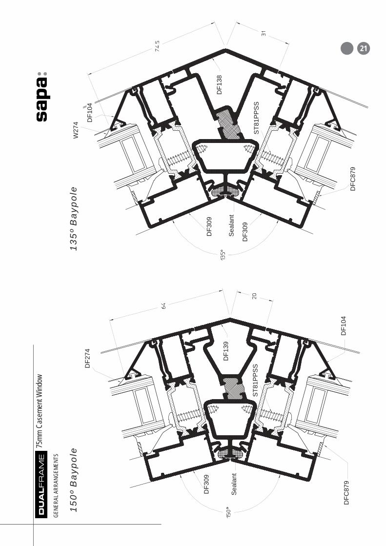
15
0º
Ba
yp
ole
13
5º
Ba
yp
ole
DF3
09
DF2
74
Sea
lant
Sea
lant
DF3
09
DF3
09
W27
4
ST8
1PP
SS
DF1
39
DF1
04D
FC87
9
DF1
04
DF1
38
DFC
879
ST8
1PP
SS
75mm
Cas
emen
t Wind
ow
GENE
RALA
RRAN
GEME
NTS
21

90
º E
xte
rna
l C
orn
er
Po
st
DF2
16
Sea
lant
DF3
09
W27
4
DF1
31
DFC
879
ST8
112P
PS
S
Pro
visi
on to
acc
ept
50m
m x
50m
m S
teel
or A
lum
iniu
m B
oxS
ectio
n, w
all
thic
knes
s w
illde
pend
on
iner
tiare
quire
men
t
75mm
Cas
emen
t Wind
ow
GENE
RALA
RRAN
GEME
NTS
22

90
º In
tern
al
Co
rne
r P
ost
Sea
lant
DFC
879
W27
4
DF3
09
DF1
04
Pro
visi
on to
acc
ept
50m
m x
50m
m S
teel
or A
lum
iniu
m B
oxS
ectio
n, w
all
thic
knes
s w
illde
pend
on
iner
tiare
quire
men
tD
F131
ST8
112P
PS
S
75mm
Cas
emen
t Wind
ow
GENE
RALA
RRAN
GEME
NTS
23

75mm
Cas
emen
t Wind
ow
GENE
RALA
RRAN
GEME
NTS
Sea
lant
DFC
879
W27
4
DF3
09
DF1
04 ST8
1PP
SS
(sta
gger
fixin
gs)
df72
5
DF3
09
W27
4
W27
4
ST8
114P
PS
S
DF3
09
Sea
lant
Va
ria
ble
Ba
yp
ole
16
2º-
17
5º
Va
ria
ble
Ba
yp
ole
13
3º-
16
3º
24

75mm
Cas
emen
t Wind
ow
GENE
RALA
RRAN
GEME
NTS
DF2
16
ST8
134P
PS
S
DF3
09
Sea
lant
W27
4
DFC
284
DF7
32
Va
ria
ble
Ba
yp
ole
11
5º-
13
4º
So
ftli
ne
Fra
me
Op
tio
n
25

ST8
112P
PS
S
DF1
04
ST8
38P
PS
SD
F165
63.5
x 6
.35
stee
l fla
t if
requ
ired
DF7
32
DF1
63
DF7
32
Sea
lant
DF1
64
DF3
09
DF7
32
75mm
Cas
emen
t Wind
ow
GENE
RALA
RRAN
GEME
NTS
Va
ria
ble
Co
rne
r P
ost
90
º-1
80
º
26

75mm
Cas
emen
t Wind
ow
GENE
RALA
RRAN
GEME
NTS
Ex
ten
de
d S
qu
are
Ou
terf
ram
e a
nd
Ch
am
fere
d V
en
tE
xte
nd
ed
So
ftlin
e O
ute
rfra
me
an
d
So
ftlin
e V
en
t
DFC
879
DF1
04
DF3
31
C50
5
DF3
05
DFC
284
C50
5
DF3
33
DF2
16
W27
4
DF3
10
DFC
284
DFC
879
27

Ch
am
fere
d M
ull
ion
/Tra
nso
m
DF3
24
DFC
284
DF3
33
C50
5
DF1
04
DFC
879
W27
4
75mm
Cas
emen
t Wind
ow
GENE
RALA
RRAN
GEME
NTS
28
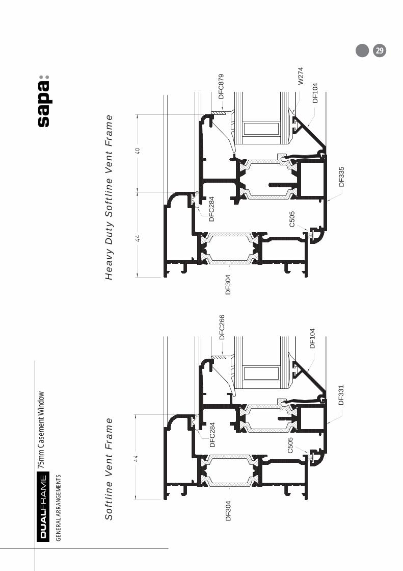
So
ftli
ne
Ve
nt
Fra
me
He
avy D
uty
So
ftlin
e V
en
t Fra
me
DF3
35
W27
4
DF1
04
DFC
879
DFC
284
C50
5
DF3
04
DF1
04
DFC
284
DFC
266
C50
5
DF3
31
DF3
04
75mm
Cas
emen
t Wind
ow
GENE
RALA
RRAN
GEME
NTS
29

75mm
Cas
emen
t Wind
ow
GENE
RALA
RRAN
GEME
NTS
DFC
879
W27
4
DF2
16
DF3
31
DF1
04
DFC
879
W27
4
DFC
284
C50
5
DF2
16
DF3
33
DF2
16
DF3
42D
F344
C50
5D
FC28
8
Wid
e S
qu
are
Mu
llio
n/T
ran
so
m w
ith
Ve
nt
Wid
e S
oft
lin
e M
ullio
n/T
ran
so
m w
ith
So
ftlin
e V
en
t
30
75mm
Cas
emen
t Wind
ow
GENE
RALA
RRAN
GEME
NTS
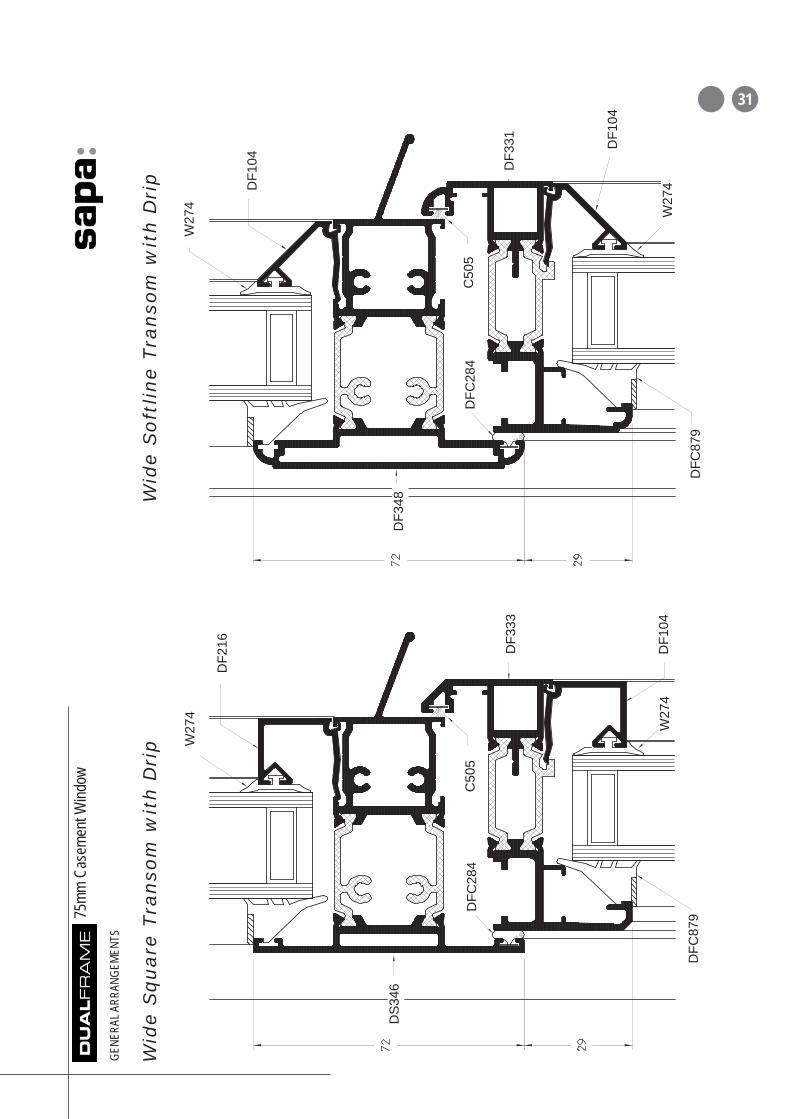
Wid
e S
qu
are
Tra
nso
m w
ith
Dri
pW
ide
So
ftlin
e T
ran
so
m w
ith
Dri
p
DFC
879
W27
4
DFC
879
DF3
48
DFC
284
C50
5
W27
4D
F104
DF3
33
W27
4
DF2
16
DS
346
DFC
284
W27
4
DF1
04 DF3
31 DF1
04
C50
5
31

W27
4
DF1
04
DF3
33
DF3
46
DFC
284
C50
5
DFC
284
C50
5
DF3
33DF1
04
DF3
48
W27
4D
FC87
9D
FC87
9
DF3
31 DF1
04
DF3
31
DFC
284
C50
5
DF1
04
C50
5D
FC28
4
75mm
Cas
emen
t Wind
ow
GENE
RALA
RRAN
GEME
NTS
Wid
e S
qu
are
Tra
nso
m
wit
h D
rip
Ve
nt/V
en
tW
ide
So
ftlin
e T
ran
so
m w
ith
Dri
p V
en
t/V
en
t32

75mm
Cas
emen
t Wind
ow
GENE
RALA
RRAN
GEME
NTS
12
0m
m M
idra
il
DFC
879
DF2
74 DF1
04
DF4
10
33

75mm
Cas
emen
t Wind
ow
GENE
RALA
RRAN
GEME
NTS
DFC
298
DF3
10
DFC
879
DF3
33 DF2
16
DFC
879
C50
5D
FC28
4
DF3
09
DFC
298
DFC
304
DFC
292
W27
4
DFC
293
DF3
33
W27
4D
F104
DFC
284
C50
5
DF1
78D
F178
FFrraa
mmee EE
xxttee
nnddee
rr//TT
rriicckkllee
VVeenntt
EExxttee
nnddeedd OO
uuttee
rrffrraa
mmee
//TTrrii
cckkllee
VVeenntt
34
75mm
Cas
emen
t Wind
ow
GENE
RALA
RRAN
GEME
NTS
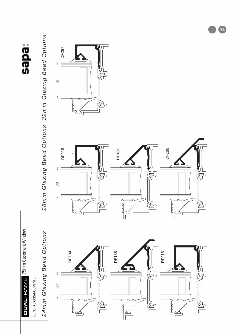
DF1
88
DF1
04
DF1
89
DF2
87
DF1
81
DF2
15
DF2
16
24
mm
Gla
zin
g B
ea
d O
pti
on
s2
8m
m G
lazi
ng
Be
ad
Op
tio
ns
32
mm
Gla
zin
g B
ea
d O
pti
on
s
34

75mm
Cas
emen
t Wind
ow
GENE
RALA
RRAN
GEME
NTS
Inte
rna
l G
laze
Ve
nt
(Sho
wing
Exte
nded
Squ
are
Fram
e &
Squa
re B
ead)
Inte
rna
l G
laze
Du
mm
y V
en
t(S
howi
ng E
xtend
ed S
quar
e Fr
ame
- note
that
squa
re b
eads
mus
talw
ays b
e us
ed w
ith In
terna
l Glaz
e Du
mmy V
ent)
36
DFC
284
C50
5
DFC
557
Pile
om
itted
at c
ill o
fdu
mm
y ve
nt

75mm
Cas
emen
t Wind
ow
GENE
RALA
RRAN
GEME
NTS
Reve
rse
Re
bate
Ad
ap
tor
DF7
35
DF3
01D
F126
Sili
cone
Sea
lant
Sili
cone
Sea
lant
DFP
267
(pk
1000
)
AF3
09(p
k 10
0)
AF1
92(p
k 50
0)
37
75mm
Cas
emen
t Wind
ow
GENE
RALA
RRAN
GEME
NTS
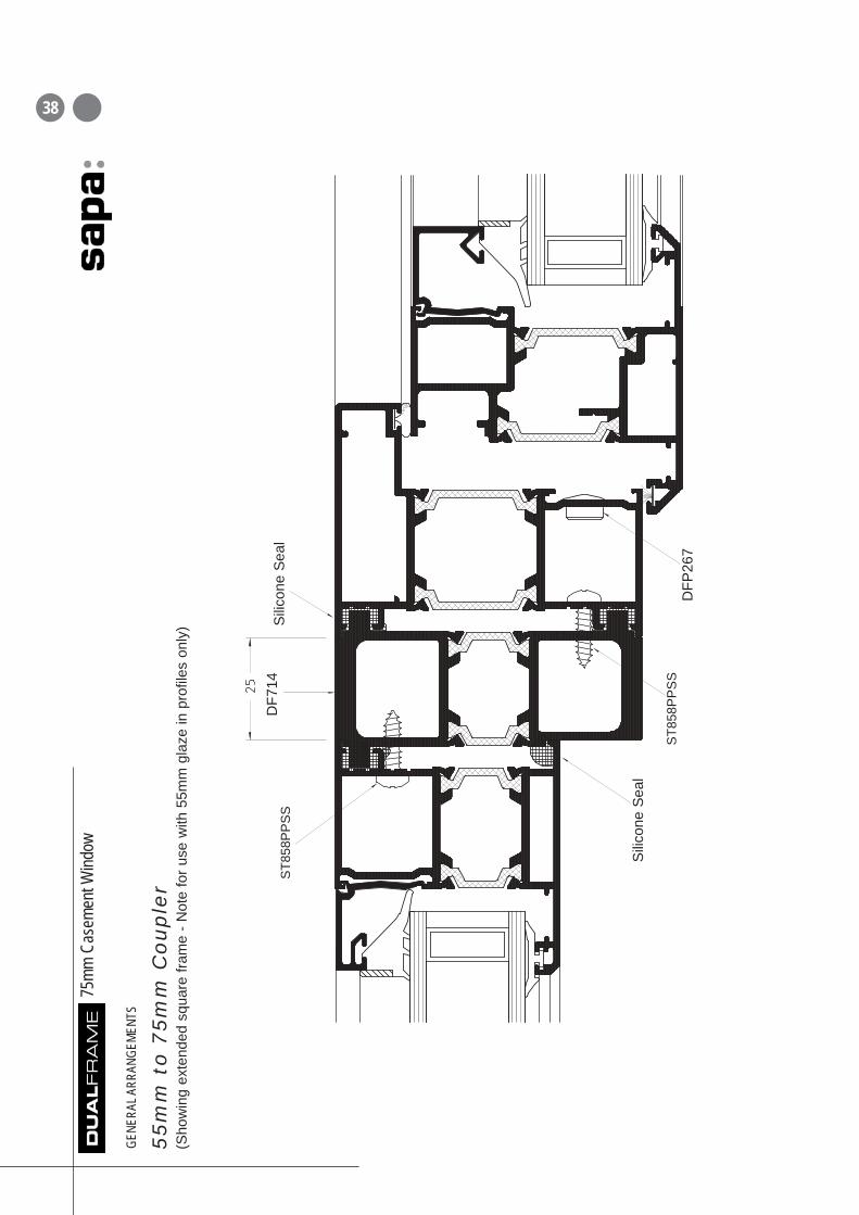
55
mm
to
75
mm
Co
up
ler
(Sho
win
g ex
tend
ed s
quar
e fra
me
- Not
e fo
r use
with
55m
m g
laze
in p
rofil
es o
nly)
ST8
58P
PS
S
ST8
58P
PS
S
Sili
cone
Sea
l
Sili
cone
Sea
l
DFP
267
DF7
14
38

This page has been left intentionally blank
39
Our policy is one of continuous development and consequently wereserve the right to vary the products and their performancespecification shown in this literature without notice.
All products and systems which Sapa supply are supplied subjectto Sapa’s standard Terms and Conditions of Sale which may varyfrom time to time.
This Technical Data Sheet is for specification guidance only. Itshould not be relied on for manufacturing or installation detailswhich must instead be obtained from Sapa Building Systems’Fabrication Manuals. For further assistance please contact one ofour Project Consultants by calling the Marketing Department onthe number below.
©© Sapa Building Systems Limited. This data sheet is issuedsubject to the condition that it shall not be reproduced without theconsent of Sapa Building Systems Limited in writing
Brochure reference DFC63 0809
Sapa Building Systems LimitedPostal address Alexandra Way, Ashchurch, Tewkesbury, Gloucestershire GL20 8NBTelephone 01684 853500 Fax 01684 851850E-mail [email protected] Website www.sapabuildingsystems.co.uk