dths 2 column - wholesale distributors arning!w this heater must be installed and serviced by...
TRANSCRIPT
DTHS SERIESTUBE HEATER
INSTALLATION, OPERATIONMAINTENANCE
AND PARTS MANUAL
Detroit Radiant Products CompanyFOR YOUR SAFETY!
IF YOU SMELL GAS:
1. Open Windows.2. Do not touch electrical switches.3. Extinguish any open flame.4. Immediately call your gas supplier.
Do not store or use gasoline or other flammablevapors and liquids in the vicinity of this or any other appliance.
FOREWORD
WARNING!
THIS HEATER MUST BE INSTALLED AND SERVICED BY TRAINED GAS INSTALLA-TION AND SERVICE PERSONNEL ONLY. READ AND UNDERSTAND THESE INSTRUC-TIONS THOROUGHLY BEFORE ATTEMPTING TO INSTALL, OPERATE OR SERVICETHE DETROIT RADIANT PRODUCTS COMPANY HEATER. FAILURE TO COMPLY WITHTHESE WARNINGS AND INSTRUCTIONS, AND THOSE ON THE HEATER, COULD RE-SULT IN PERSONAL INJURY, DEATH, FIRE, ASPHYXIATION, AND/OR PROPERTY DAM-AGE. RETAIN THESE INSTRUCTIONS FOR FUTURE REFERENCE.
Approval Standards and Certifications
Detroit Radiant Products units comply with or are certified by the following Organizations or Standards:
Any alteration of the system or of the factory authorized components specified either in this manual or by Detroit RadiantProducts Company voids all certification and warranties.
Detroit Radiant Products Company21400 Hoover Road ♦ Warren MI 48089 ♦ (586) 756-0950 ♦ Fax: (586) 756-2626
http://www.reverberray.com E-mail: [email protected]
� American National Standards (ANSI Z83.6)� Occupational Safety and Health Act (OSHA)� American Gas Association (AGA)� International Approval Services (IAS)
TABLE OF CONTENTS PAGE
1. INSTALLATION
1.1 Design Criteria 4
1.2 Prechecks 4
1.3 Heater Mounting 6
1.4 Reflector Assembly 8
1.5 Optional “L” or “U” Configuration 10
1.6 Flue Venting 12
1.7 Installation for Unvented Operation (Optional) 14
1.8 Combustion Air Requirements 16
1.9 Gas Supply 17
1.10 Electrical Requirements 18
1.11 Lighting Instructions 20
1.12 Shutdown Instructions 21
2. THEORY OF OPERATION 21
2.1 DTHS-2 Models: 40,000 BTU/H through 100,000 BTU/H Input 22
3. MAINTENANCE 22
4. TROUBLESHOOTING 24
4.1 Glo-Bar Replacement 25
4.2 Gas Valve Testing (Part No. TP 36) 25
4.3 Troubleshooting Chart 26
5. PARTS LIST
5.1 Basic Parts List 28
5.2 DTHS Parts Blow-up 29
1
SAFETY INFORMATION
• This infra-red heater is designed for use in industrial and commercial buildings such as warehouses, manu-facturing plants, aircraft hangars, service garages, etc.
NOT FOR RESIDENTIAL USE!Do not use the home, sleeping quarters, attached garages, etc.
• Detroit Radiant Products Company cannot anticipate every use, which may be made of their heaters. Checkwith your local fire safety authority if you have questions about local regulations.
The following information must be reviewed before installing this heater
WARNING!This is not an explosion-proof heater. Where there is the possibility of exposure to flammable vapors, consult the local firemarshal, the fire insurance carrier or other authorities for approval of the proposed installation.
• Check the AGA rating label on the heater to verify the minimum clearances to combustibles and the proper gasto be used. Check the other labels on the heater to verify proper mounting.
• The installation of this heater must conform with local building codes or, in the absence of local codes, with thelatest edition of the National Fuel Gas Code, ANSI-Z223. 1 (NFPA 54).
• The installation of this heater in public garages must conform with the Standard for Parking Structures, ANSI/NFPA 88A-latest edition or the Standard for Repair Garages, ANSI/NFPA 88B-latest edition and must be atleast 8 ft. above the floor.
• The installation of this heater in aircraft hangars must conform with the Standard for Aircraft Hangars, ANSI/NFPA 409 latest edition. The heater must be installed at least 10 ft. above the upper wing surfaces and engineenclosures of the highest aircraft which might be stored in the hangar. In areas adjoining the aircraft storagearea, the heaters must be installed at least 8 ft. above the floor. The heaters must be located in areas where theywill not be subject to damage by aircraft, cranes, movable scaffolding or other objects.
• The heater, when installed, must be electrically grounded in accordance with the latest edition of the NationalElectrical Code, ANSI/NFPA 70.
• Under no circumstance is either the gas supply line or the electrical supply line to the heater to provide anyassistance in the suspension of the heater.
• The weight of the heater must be entirely suspended from a permanent part of the building structure havingadequate load characteristics.
• Neither the gas supply line, electrical supply line nor sprinkler heads shall be located within the minimumclearances to combustibles as shown in the Clearances to Combustibles Chart on page 3.
• Signs should be posted in storage areas to specify maximum stacking height allowed in order to maintainclearance to combustibles.
F O R Y O U R S A F E T Y !
D o n o t s to re o r u se g aso lin e o r o the rflam m ab le v apo rs an d liq u id s in thev ic in ity o f th is o r any o th e r ap p lian ces .
F O R Y O U R S A F E T Y !IF Y O U S M E L L G A S :1 . O p en w in d o w s.2 . D o n o t to u ch e lec trica l sw itch es.3 . E x tin g u ish an y o p en flam e .4 . Im m ed ia te ly ca ll y o u r g as
su p p lie r.
2
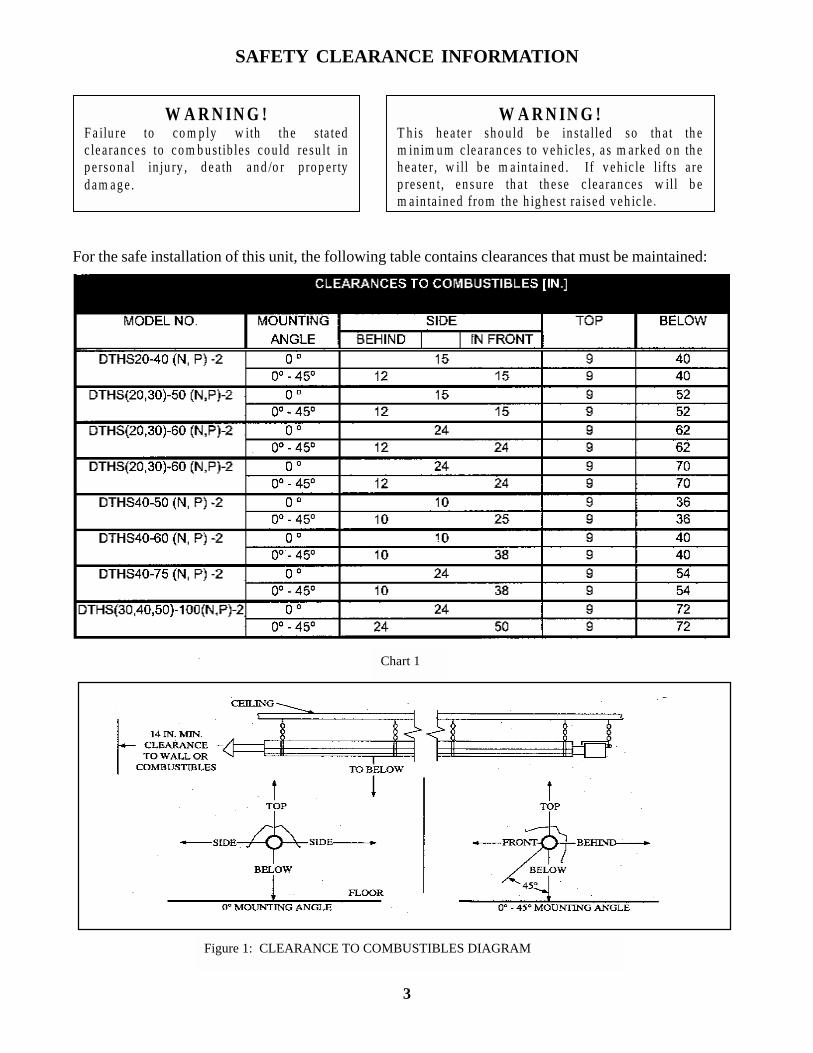
SAFETY CLEARANCE INFORMATION
W A R N IN G !F a ilu re to co m p ly w ith th e s ta tedc learanc es to co m b u stib le s co u ld re su lt inp e rso n a l in ju ry , d e a th an d /o r p ro p ertyd am ag e .
W A R N IN G !T h is hea te r sh o u ld b e in sta lled so th a t th em in im u m c lea ran ce s to v eh ic le s , a s m ark ed o n th eh ea te r , w ill b e m a in ta in ed . If v eh ic le lifts a rep re sen t, en su re th a t th e se c learan ces w ill b em ain ta ined from the h ig h es t ra ised veh ic le .
For the safe installation of this unit, the following table contains clearances that must be maintained:
Chart 1
Figure 1: CLEARANCE TO COMBUSTIBLES DIAGRAM
3

INSTALLATION
1.1 Design Criteria
Perimeter mounting of these infrared heaters providesfor the most efficient installation. In Figure 1-1, the heat-ers are mounted at the perimeter of the space to be heated.Refer to the DTHS
Heater Installation Chart for the recommended distanceson the models being installed. Buildings that require therows of heaters to be farther apart than the recommendeddistance in the chart may need additional heaters placedin the center of the space.
Chart 2
NOTE: This chart is provided as a guideline. Actual conditions may dictate variation form this data
T Y P IC A L B U IL D IN G L A Y O U T
F ig u re 1 -1
4

When positioning heaters, keep in mind the clear-ancesto combustible materials, lights, sprinkler heads, over-head doors, storage areas with stacked materials, gas andelectrical lines, parked vehicles, cranes and any otherpossible obstructions or haz-ards. Refer to the warn-ings, cautions and the Clearance to Combustibles Chart(1) on page 3 and on the heater to verify that a safe in-stallation condition exists.
The following guidelines must also be met to ensure agood installation and proper heater performance:
• A maximum of two 90° elbows (factory suppliedPart No. E6 only) can be installed on DTHS modelheaters. The gas input of the heaters, as stated on therating label, will de-termine the minimum length ofthe 4 in. diameter emitter pipe from the control boxto the first elbow. (See Section 2.5, Optional “L” or“U” Configuration).
NOTE: Flue vent requirements do not change when el-bows are installed.
• Do not exceed the maximum vent length (usu-ally20 ft.) for exhausting the heater. Consult the FlueVenting Chart on page 14.
• Do not combine the exhaust vents of two heaters intoa straight through tee. A Part No. Y or staggered teearrangement must be used. Heaters sharing the samevent must share the same thermostat. Common ventsmust have a 6 in. diameter. Common vents musthave a 6 in. diameter flue (see Figure 1-1).
• Non-contaminated air for combustion must be ductedto the heater if chlorinated or fluorinated contami-nants are present in the area where the heater is in-stalled. Consult Combustion Air Requirements sec-tion on page 17.
• Do not exceed the maximum duct length for freshair intake (usually 20 ft). Consult Air Intake DuctChart on page 17.
• Do not draw fresh air to the heater from an attic space.There is no guarantee that adequate air will be sup-plied.
• All unvented heaters must use part no. WVE-GALVvent with flapper.
Once all of the safety precautions and design criteria aremet, the actual installation of the heater may begin.
W A R N IN G !T h e ce ilin g to p c le a ran c e m u st b e a m in im u m o f1 5 in . fo r h ea te rs w ith a g as in p u t ra tin g o f 6 0 ,0 0 0 a n d7 5 ,0 0 0 B T U /H an d o n ly 1 0 f t. o f 4 in . d ia m e te r e m itte rp ip e to th e f irs t e lb o w . A ll o th er c le a ran c es a re as s ta te din th e C le a ran c e to C o m b u stib les C h a rt (1 ) o n p a g e 3 .
5
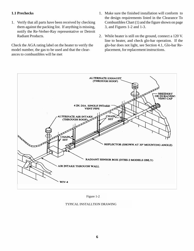
1.1 Prechecks
1. Verify that all parts have been received by checkingthem against the packing list. If anything is missing,notify the Re-Verber-Ray representative or DetroitRadiant Products.
Check the AGA rating label on the heater to verify themodel number, the gas to be used and that the clear-ances to combustibles will be met
1. Make sure the finished installation will conform tothe design requirements listed in the Clearance ToCombustibles Chart (1) and the figure shown on page3, and Figures 1-2 and 1-3.
2. While heater is still on the ground, connect a 120 V.line to heater, and check glo-bar operation. If theglo-bar does not light, see Section 4.1, Glo-bar Re-placement, for replacement instructions.
Figure 1-2
TYPICAL INSTALLTION DRAWING
6

F ig u re 1 -3
D IM E N S IO N S F O R M O D E L S : D T H S 2 0 , 3 0 , 4 0 A N D 5 0 IN F R A -R E D T U B E H E A T E R
7

1.3 Heater Mounting
1. Each heater comes equipped with the necessary hang-ers (Figure 1-4) for hanging. The DTHS 20 requiresthree hangers, the DTHS 30 four hangers, the DTHS40 five hangers, and the DTHS 50 six hangers. Eachheater also comes with one reflector center support(Figure 1-5) for the first 10 ft. section of reflectorand one DTHS installation kit.
1. Use of #1 double-loop chain is recommended forheater hanging (Accessory No. THCS) (see Figure1-6). Close all “S” hooks to ensure maximum loadcarrying capacity. Accessory No. “BK” allows forpreset mounting angle of 15°, 30°, or 45°.
Figure 1-4
Figure 1-5
Figure 1-6
NOTE: If windy conditions exist in the space aroundthe heater, it may be necessary to rigidly mount the heaterto prevent swaying. It is recommended that threadedrod be used for the two hanging points at the burner con-trol box (see Figure 1-7). The remaining hanging pointsshould use chains to allow for heater expansion.
IMPORTANT: The first 10 ft. tube on DTHS (40,50)-100P (propane) and DTHS 30-100, must be a titaniumalloy, aluminized steel tube (Alumi-Ti).
1. Mount hangers on approximately 10 ft. centers. Slidetubes through hangers with weld seam downward (seeFigure 1-8) and fasten with tube clamps (see Figure1-9). Center clamps on seams.
NOTE: The tube clamps provided with the heater arepre-assembled at the factory. If a clamp is dismantled, itis important that upon reassembly the spacer is properlyinserted (see Figure 1-9). The spacer’s concave surfacemust face the radiant tube. Incorrect spacer placementwill result in shearing of the bolt when torqued to therecommended specification (50-70 lb.-ft).
Figure 1-7
Figure 1-8
8
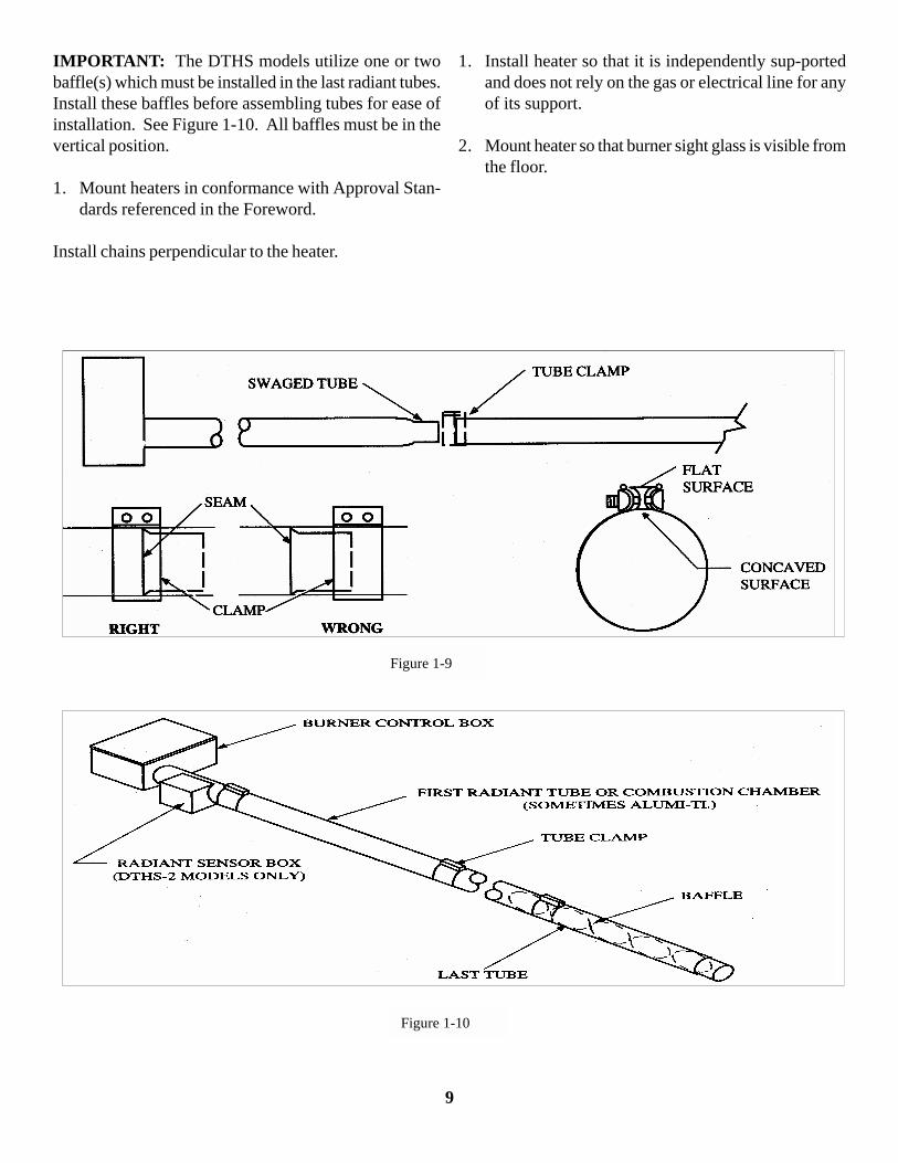
IMPORTANT: The DTHS models utilize one or twobaffle(s) which must be installed in the last radiant tubes.Install these baffles before assembling tubes for ease ofinstallation. See Figure 1-10. All baffles must be in thevertical position.
1. Mount heaters in conformance with Approval Stan-dards referenced in the Foreword.
Install chains perpendicular to the heater.
1. Install heater so that it is independently sup-portedand does not rely on the gas or electrical line for anyof its support.
2. Mount heater so that burner sight glass is visible fromthe floor.
Figure 1-9
Figure 1-10
9
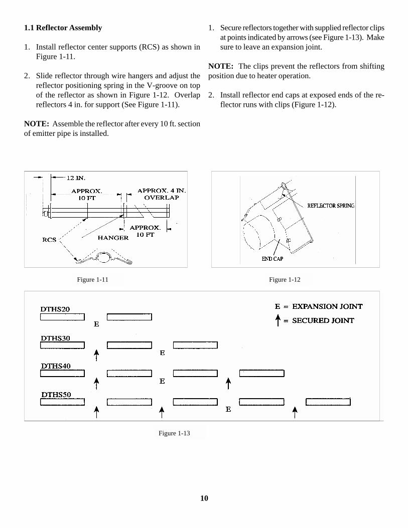
1.1 Reflector Assembly
1. Install reflector center supports (RCS) as shown inFigure 1-11.
2. Slide reflector through wire hangers and adjust thereflector positioning spring in the V-groove on topof the reflector as shown in Figure 1-12. Overlapreflectors 4 in. for support (See Figure 1-11).
NOTE: Assemble the reflector after every 10 ft. sectionof emitter pipe is installed.
1. Secure reflectors together with supplied reflector clipsat points indicated by arrows (see Figure 1-13). Makesure to leave an expansion joint.
NOTE: The clips prevent the reflectors from shiftingposition due to heater operation.
2. Install reflector end caps at exposed ends of the re-flector runs with clips (Figure 1-12).
Figure 1-11 Figure 1-12
Figure 1-13
10

Optional Side Shield Installation
1. Install an additional 2 reflector center supports (RCS)4 ft. on each side of the standard RCS.
2. Install the side shield by hooking the edge holes ontothe RCS’s (Figure 1-14).
Figure 1-14
11
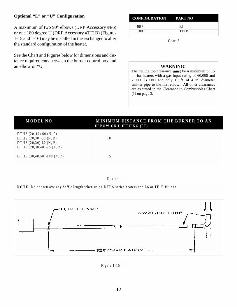
Optional “L” or “U” Configuration
A maximum of two 90° elbows (DRP Accessory #E6)or one 180 degree U (DRP Accessory #TF1B) (Figures1-15 and 1-16) may be installed in the exchanger to alterthe standard configuration of the heater.
See the Chart and Figures below for dimensions and dis-tance requirements between the burner control box andan elbow or “U”.
90 ° E6 180 ° TF1B
Chart 3
CONFIGURATION PART NO
WARNING!The ceiling top clearance must be a minimum of 15in. for heaters with a gas input rating of 60,000 and75,000 BTU/H and only 10 ft. of 4 in. diameteremitter pipe to the first elbow. All other clearancesare as stated in the Clearance to Combustibles Chart(1) on page 3.
M O D E L N O . M IN IM U M D IS T A N C E F R O M T H E B U R N E R T O A N E L B O W O R U F IT T IN G (F T )
D T H S (2 0 -4 0 )-6 0 (N , P )D T H S (2 0 ,3 0 )-5 0 (N , P ) 1 0D T H S (2 0 ,3 0 )-6 0 (N , P )D T H S (2 0 ,3 0 ,4 0 )-7 5 (N , P )
D T H S (3 0 ,4 0 ,5 0 )-1 0 0 (N , P ) 1 5
F ig u re 1 -1 5
N O T E : D o n o t re m o v e a n y b a ff le le n g th w h en u s in g D T H S se r ie s h e a te rs a n d E 6 o r T F 1 B f itt in g s .
C h a r t 4
12
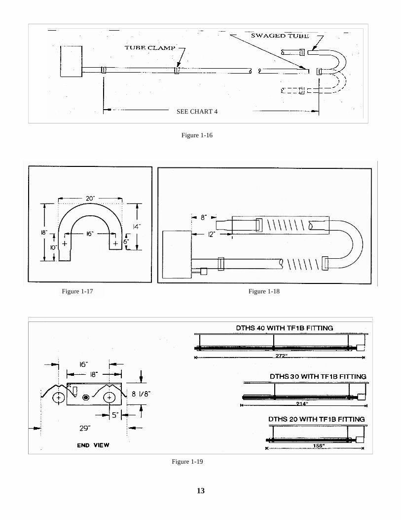
Figure 1-17
Figure 1-16
Figure 1-18
Figure 1-19
SEE CHART 4
13
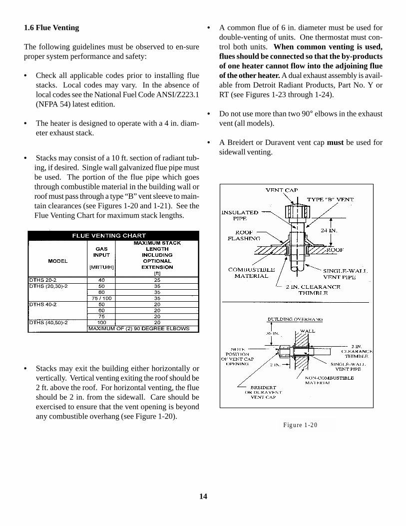
1.6 Flue Venting
The following guidelines must be observed to en-sureproper system performance and safety:
• Check all applicable codes prior to installing fluestacks. Local codes may vary. In the absence oflocal codes see the National Fuel Code ANSI/Z223.1(NFPA 54) latest edition.
• The heater is designed to operate with a 4 in. diam-eter exhaust stack.
• Stacks may consist of a 10 ft. section of radiant tub-ing, if desired. Single wall galvanized flue pipe mustbe used. The portion of the flue pipe which goesthrough combustible material in the building wall orroof must pass through a type “B” vent sleeve to main-tain clearances (see Figures 1-20 and 1-21). See theFlue Venting Chart for maximum stack lengths.
• Stacks may exit the building either horizontally orvertically. Vertical venting exiting the roof should be2 ft. above the roof. For horizontal venting, the flueshould be 2 in. from the sidewall. Care should beexercised to ensure that the vent opening is beyondany combustible overhang (see Figure 1-20).
• A common flue of 6 in. diameter must be used fordouble-venting of units. One thermostat must con-trol both units. When common venting is used,flues should be connected so that the by-productsof one heater cannot flow into the adjoining flueof the other heater. A dual exhaust assembly is avail-able from Detroit Radiant Products, Part No. Y orRT (see Figures 1-23 through 1-24).
• Do not use more than two 90° elbows in the exhaustvent (all models).
• A Breidert or Duravent vent cap must be used forsidewall venting.
F ig u re 1 -2 0
14
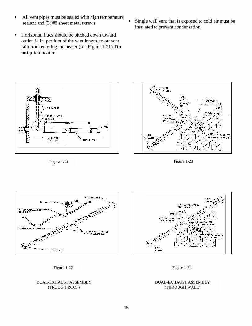
• All vent pipes must be sealed with high temperaturesealant and (3) #8 sheet metal screws.
Figure 1-21 Figure 1-23
Figure 1-22 Figure 1-24
DUAL-EXHAUST ASSEMBLY(TROUGH ROOF)
DUAL-EXHAUST ASSEMBLY(THROUGH WALL)
• Horizontal flues should be pitched down towardoutlet, ¼ in. per foot of the vent length, to preventrain from entering the heater (see Figure 1-21). Donot pitch heater.
• Single wall vent that is exposed to cold air must beinsulated to prevent condensation.
15
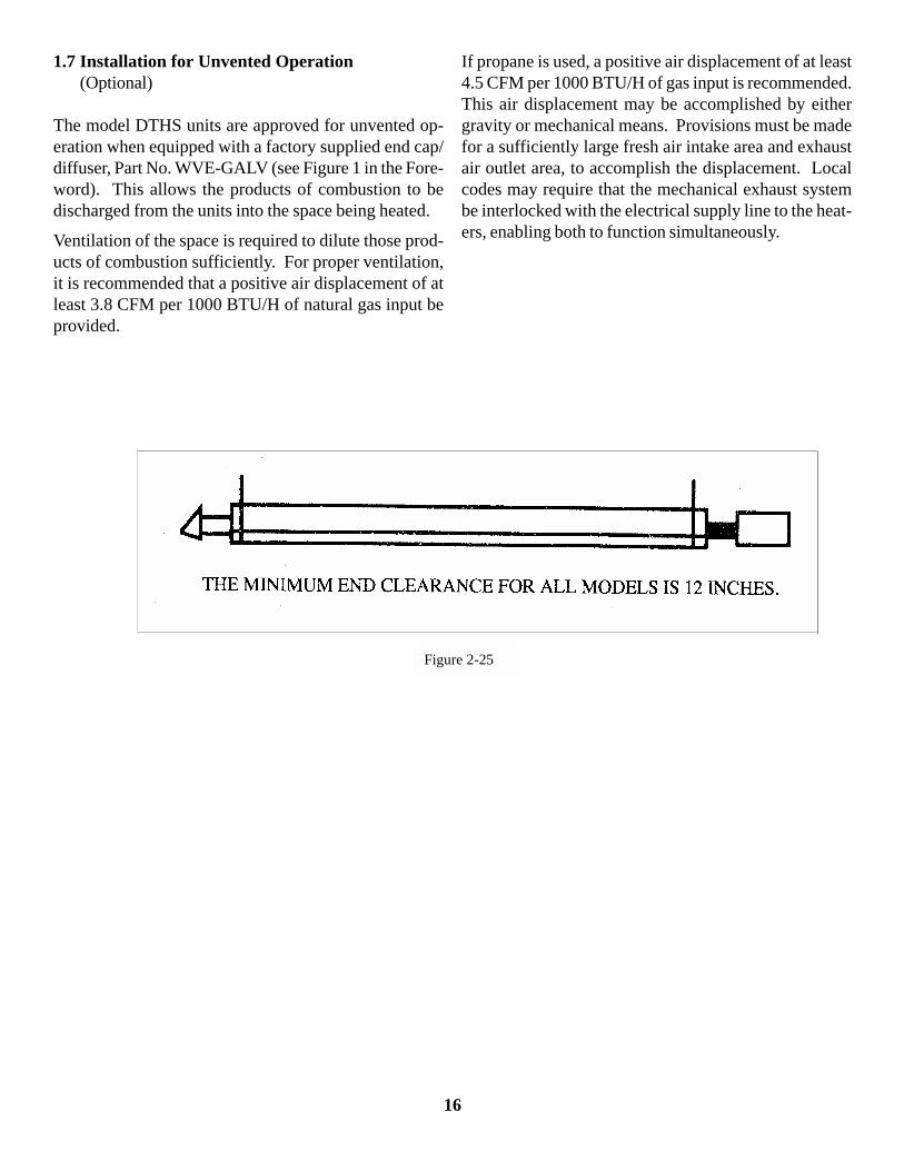
1.7 Installation for Unvented Operation(Optional)
The model DTHS units are approved for unvented op-eration when equipped with a factory supplied end cap/diffuser, Part No. WVE-GALV (see Figure 1 in the Fore-word). This allows the products of combustion to bedischarged from the units into the space being heated.
Ventilation of the space is required to dilute those prod-ucts of combustion sufficiently. For proper ventilation,it is recommended that a positive air displacement of atleast 3.8 CFM per 1000 BTU/H of natural gas input beprovided.
If propane is used, a positive air displacement of at least4.5 CFM per 1000 BTU/H of gas input is recommended.This air displacement may be accomplished by eithergravity or mechanical means. Provisions must be madefor a sufficiently large fresh air intake area and exhaustair outlet area, to accomplish the displacement. Localcodes may require that the mechanical exhaust systembe interlocked with the electrical supply line to the heat-ers, enabling both to function simultaneously.
Figure 2-25
16

Figure 1-26
1.8 Combustion Air Requirements
Combustion air intake has a factory preset air orifice. Ifindoor combustion air is to be supplied for a tightly closedroom, one square inch of free air opening should be pro-vided for each 5000 BTU/H of heater input.
Noncontaminated air for combustion must be ducted tothe heater if chlorinated or fluorinated contaminants arepresent in the area where the heater is installed, or if thebuilding has a negative pressure. Typical sources of thesecontaminants are refrigerants, solvents, adhesives,degreasers, paint removers, paints, lubricants, pesticides,etc.
Outside combustion air may be provided by a 4 in. airduct directly attached over the air orifice collar (see Fig-ure 1-26). A WIV-4 wall inlet vent must be used withhorizontal outside air intake ducts.
NOTE: Use insulated duct or PVC pipe to prevent con-densation on outer surface. Keep intake opening at least3 ft. from any exhaust vent openings. For limitations oflength and size, see the Air Intake Duct Chart.
17

1.9 Gas Supply
CORRECT INLET PRESSURES ARE VITAL FOREFFICIENT OPERATION OF HEATERS. REFERTO AGA RATING LABEL AND CONSULT GASCOMPANY IF NECESSARY.
If all or a portion of the gas supply line consists of usedpipe, it must be cleaned and then inspected to determineits equivalency to new pipe. Test all main supply linesaccording to local codes. (Isolate heater gas valve andsupplied gas cock during test.)
Excessive torque on manifold may misalign orifice. Al-ways use two wrenches when tightening mating pipe con-nections.
If any portion of the gas supply line is located in an areathat could cause an abnormal amount of con-densate tooccur in the pipe, a sediment trap should be installed(see Figure 1-27).
WARNING!Never use a match or any other flame to testfor gas leaks. Use soap and water to checkfor leaks.
Figure 1-27
NOTE: For high pressure gas above 14 in. W.C.P. (Wa-ter Column Pressure), a high pressure regulator and gascock must be used. If compressed air is used to detectleaks in the gas supply line, disconnect and cap at shut-off cock to avoid damage to regulator and gas valve.
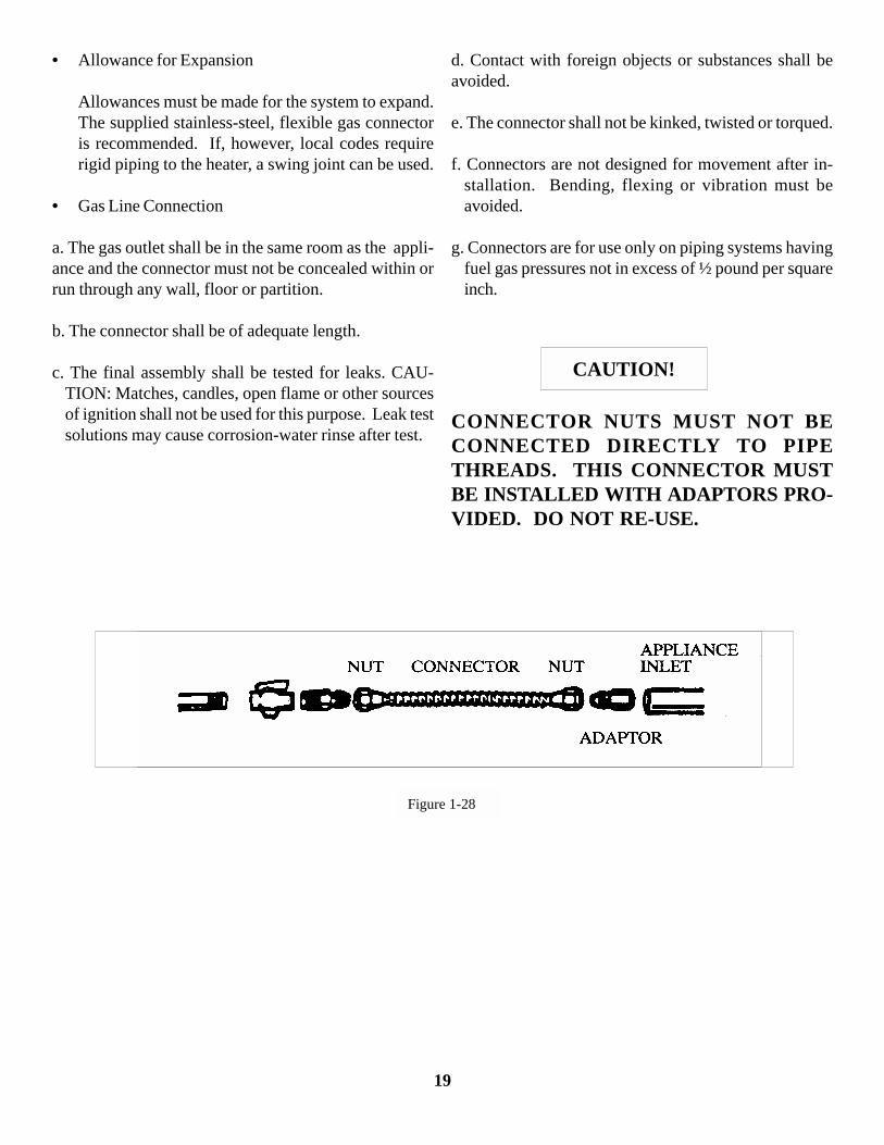
A typical gas supply line connection is illustrated in Fig-ure 1-28. The method shown will decrease the possibil-ity of any loose scale or dirt in the supply line enteringthe heater’s control system and causing a malfunction.Provide a 1/8 in. NPT, plugged tapping accessible fortest gauge connection immediately upstream of gas con-nection to heater. The gas supply line must be of suffi-cient size to provide the required capacity and inlet pres-sure to the heater (consult gas company) as follows:
NOTE: Manifold pressure should be checked at the tapon the gas valve. Readings will be above atmosphericpressure.
• Natural Gas
To obtain the required manifold pressure of 3.8 in.W.C.P., a minimum inlet pressure of 4.8 in. W.C.P.is necessary for purposes of input adjustment. Amaximum inlet pressure of 14.0 in. W.C.P. is al-lowed for all units.
• Propane Gas
To obtain the required manifold pressure of 10.0 in.W.C.P., a minimum of 11.0 in. W.C.P. for 14.0 in.W.C.P. must be provided ahead of the control sys-tem on each heater. Do not exceed a manifold oper-ating pressure of 10.0 in. W.C.P.
Use only a pipe-joint compound that is resistant toliquefied petroleum gases.
• Pressure Equivalents
1 in. W.C.P. equals 0.58oz/sq. in. 4.8 in. W.C.P. equals 2.78oz/sq. in.
6 in. W.C.P. equals 3.48oz/sq. in. 11 in. W.C.P. equals 6.38oz/sq. in. 14 in. W.C.P. equals 8.12oz/sq. in.
18
• Allowance for Expansion
Allowances must be made for the system to expand.The supplied stainless-steel, flexible gas connectoris recommended. If, however, local codes requirerigid piping to the heater, a swing joint can be used.
• Gas Line Connection
a. The gas outlet shall be in the same room as the appli-ance and the connector must not be concealed within orrun through any wall, floor or partition.
b. The connector shall be of adequate length.
c. The final assembly shall be tested for leaks. CAU-TION: Matches, candles, open flame or other sourcesof ignition shall not be used for this purpose. Leak testsolutions may cause corrosion-water rinse after test.
d. Contact with foreign objects or substances shall beavoided.
e. The connector shall not be kinked, twisted or torqued.
f. Connectors are not designed for movement after in-stallation. Bending, flexing or vibration must beavoided.
g. Connectors are for use only on piping systems havingfuel gas pressures not in excess of ½ pound per squareinch.
CONNECTOR NUTS MUST NOT BECONNECTED DIRECTLY TO PIPETHREADS. THIS CONNECTOR MUSTBE INSTALLED WITH ADAPTORS PRO-VIDED. DO NOT RE-USE.
CAUTION!
Figure 1-28
19
1.10 Electrical Requirements
1. Heaters operate on 120V, 60 Hz, single phase. Themaximum amperage requirement (starting current)is 4.8 amps per heater. The running current is 1.1amps.
2. Heater must be grounded in accordance with theNational Electrical Code ANSI/NFPA 70 (latest edi-tion).
1. It is recommended that the thermostat be installed onthe hot side of a fused supply line and have a suffi-cient ampere rating for the heater(s) it controls.
1. Wiring must not be run above or below the heater,nor exposed to the radiant output.
2. Observe proper electrical polarity.
20

1.11 Lighting Instructions
1. Purge main gas supply line at start-up.
2. Rotate heater’s manual gas valve knob to the “ON”position.
3. Close electrical circuit.
4. If heater fails to light, turn off gas and wait five min-utes before repeating the above procedure.
1.12 Shutdown Instructions
1. Open electrical circuit.
2. Rotate heater’s manual gas valve knob to the “OFF”position.
21
1 THEORY OF OPERATION
1.1 DTHS-2 Models: 40,000 BTU/H through 100,000BTU/H
• Starting Circuit (Figures 2-1 and 2-2)
When voltage is applied to L1 and L2, a circuit is com-pleted from L1 via the blower motor to L2. The blowerfan is mounted in the control box and rated to supplysufficient air for combustion.
Air pressure generated by the blower will cause the nor-mally open burner pressure switch No. 1 to close. Theburner pressure switch is factory preset to ensure that aminimum of 2/3 the normal rate of combustion air ispassed into the combustion chamber. Any air flow re-striction resulting in less than 2/3 normal rate will causethe pressure switch to open and shut down the entire sys-tem.
Current will pass through the burner pressure switch tothe normally closed exhaust pressure switch No. 2. Theexhaust pressure switch is factory preset to ensure that aminimum of ½ the normal rate of exhaust air is expelledfrom the heater. Any air flow restriction resulting in lessthan ½ normal rate will cause the pressure switch to openand shut down the entire system.
NOTE: Pressure switches are nonadjustable.
Another circuit is completed from L1 to the radiant sen-sor and glo-bar back to L2. Simultaneously, the safetyand booster coils of the first of two redundant valves areenergized through the contact of the radiant sensor. Thiscauses the first valve to open and the glo-bar to heat up.No gas flows however, until the second redundant valveis energized and opened.
• Running Circuit
When the glo-bar reaches ignition temperature, the radi-ant sensor is heated and opens (maximum 60 seconds).The radiant sensor is a heat sensitive bimetal switch witha single throw contact that is normally in the closed posi-tion and calibrated to open when the glo-bar has attainedignition temperature.
The second redundant valve, now in series with the glo-bar, is energized and opened. Gas flows through theburner and is ignited by the glo-bar. The second coilremaining in series with the glo-bar causes the glo-bar tocool down. The radiant sensor is held open by radiantheat emitted from the gas flame. The booster coil of thefirst valve is now placed in series with the secondarycoil, and very low current flows through the coil. Thesafety coil power is sufficient to hold only the first valveopen . If a momentary power failure occurs, the firstvalve will shut down the gas supply to the burner. Whenpower is restored, the safety coil alone does not have thepower to pull the valve open, therefore, the radiant sen-sor cools down, the contacts close and the unit cycles(maximum 60 seconds).
22
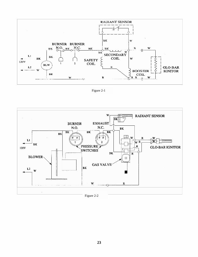
Figure 2-1
Figure 2-2
23
MAINTENANCE
Model DTHS gas-fired, infrared heaters require a mini-mum of routine maintenance to keep them operating atpeak performance.
1. Ensure that the squirrel cage in the blower is keptclean. If dirt becomes a problem, installation of out-side air intake ducts for combustion is recommended.Oiling the blower motor will extend bearing life be-yond the 30,000 hour minimum.
2. Keep the aluminum reflectors clean.
WARNING!Use protective glasses when cleaning the heater.
24
4 TROUBLESHOOTING
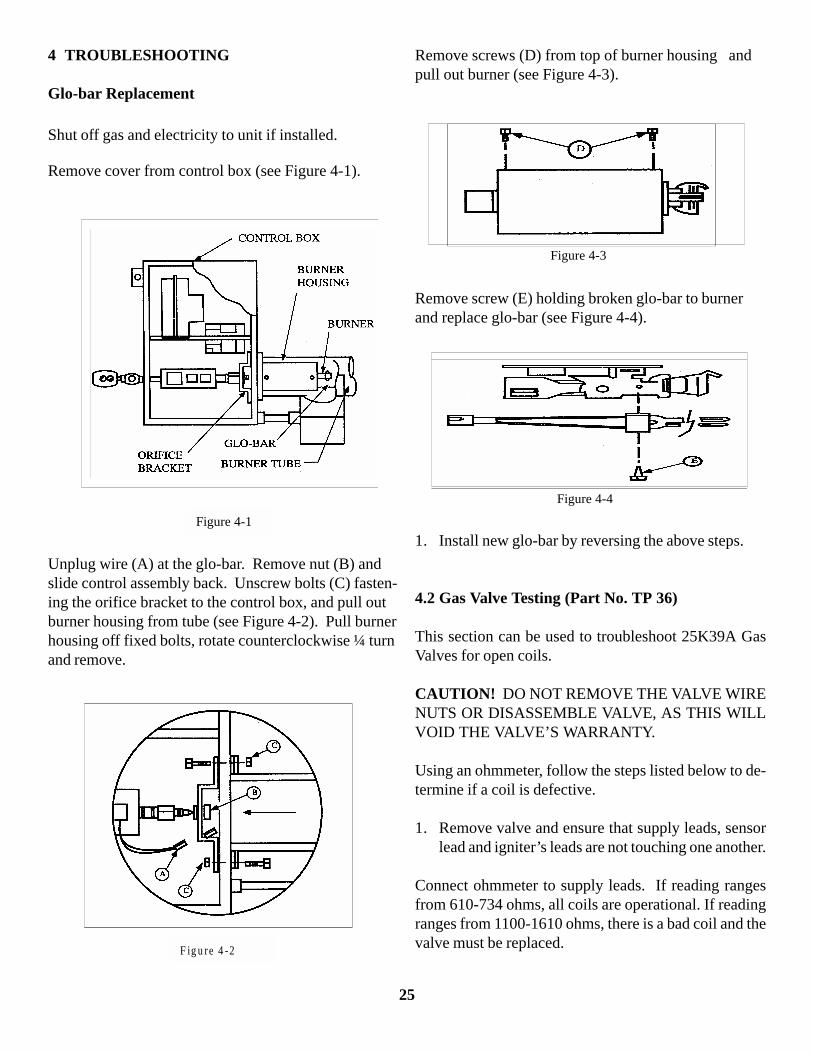
Glo-bar Replacement
Shut off gas and electricity to unit if installed.
Remove cover from control box (see Figure 4-1).
Unplug wire (A) at the glo-bar. Remove nut (B) andslide control assembly back. Unscrew bolts (C) fasten-ing the orifice bracket to the control box, and pull outburner housing from tube (see Figure 4-2). Pull burnerhousing off fixed bolts, rotate counterclockwise ¼ turnand remove.
Figure 4-1
F ig u re 4 -2
Remove screws (D) from top of burner housing andpull out burner (see Figure 4-3).
Remove screw (E) holding broken glo-bar to burnerand replace glo-bar (see Figure 4-4).
1. Install new glo-bar by reversing the above steps.
4.2 Gas Valve Testing (Part No. TP 36)
This section can be used to troubleshoot 25K39A GasValves for open coils.
CAUTION! DO NOT REMOVE THE VALVE WIRENUTS OR DISASSEMBLE VALVE, AS THIS WILLVOID THE VALVE’S WARRANTY.
Using an ohmmeter, follow the steps listed below to de-termine if a coil is defective.
1. Remove valve and ensure that supply leads, sensorlead and igniter’s leads are not touching one another.
Connect ohmmeter to supply leads. If reading rangesfrom 610-734 ohms, all coils are operational. If readingranges from 1100-1610 ohms, there is a bad coil and thevalve must be replaced.
Figure 4-3
Figure 4-4
25
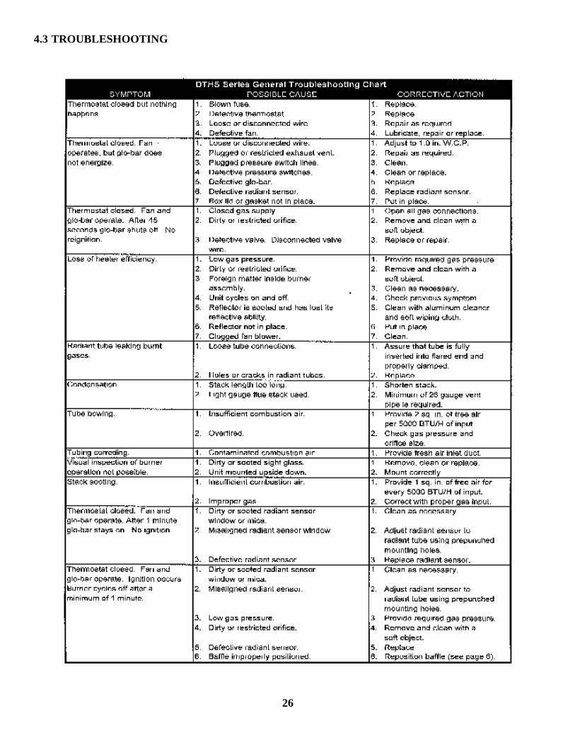
4.3 TROUBLESHOOTING
26

27
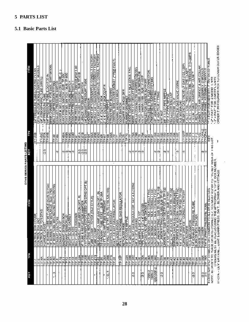
5 PARTS LIST
5.1 Basic Parts List
28
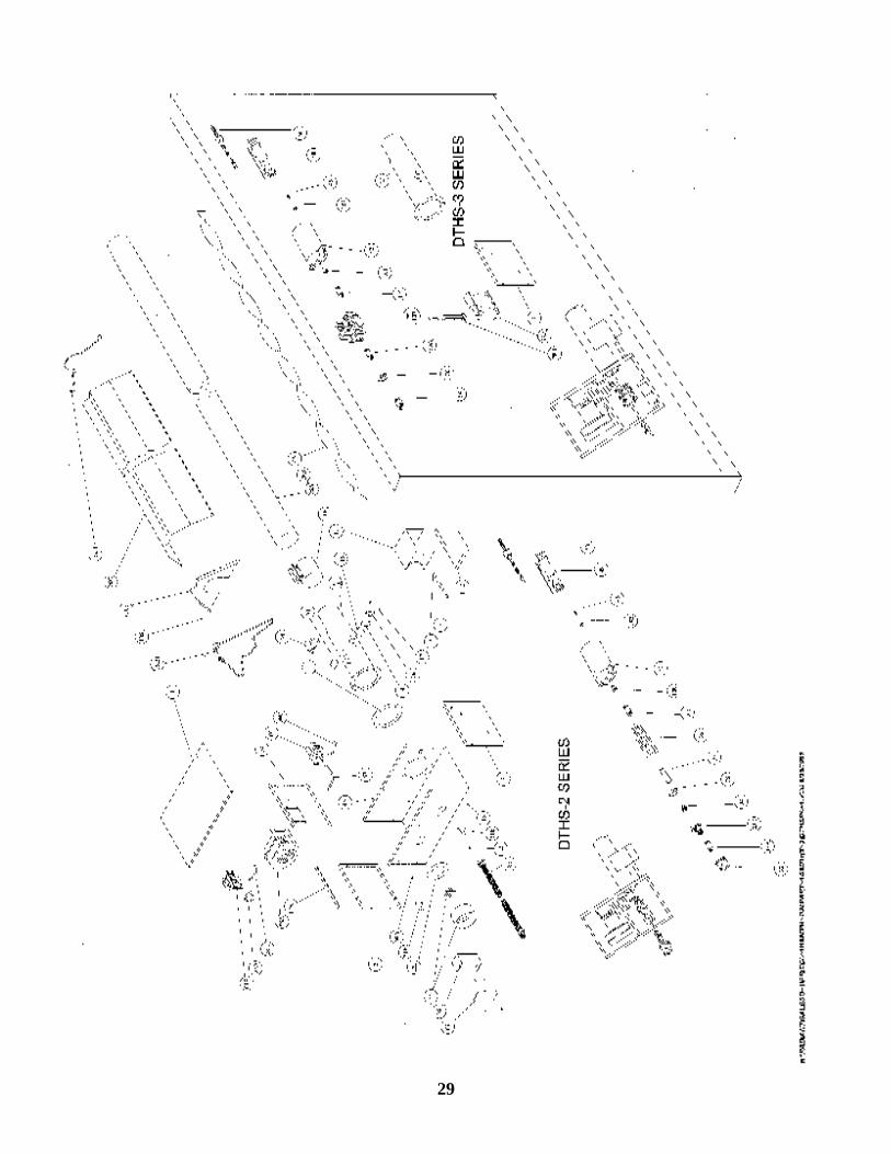
29