dse 890 development configuration tool - sds drives · 2013-07-23 · dse 890 configuration tool....
TRANSCRIPT

DSE 890 Configuration Tool
DSE 890 DevelopmentConfiguration ToolSoftware ManualHA471113U001 Issue 4
Compatible with Version 1.x Software
Copyright SSD Drives Limited 2006
All rights strictly reserved. No part of this document may be stored in a retrieval system, ortransmitted in any form or by any means to persons not employed by a SSD Drives companywithout written permission from SSD Drives Ltd. Although every effort has been taken to ensurethe accuracy of this document it may be necessary, without notice, to make amendments or correctomissions. SSD Drives cannot accept responsibility for damage, injury, or expenses resultingtherefrom.
WARRANTY
SSD Drives warrants the goods against defects in design, materials and workmanship for theperiod of 12 months from the date of delivery on the terms detailed in SSD Drives StandardConditions of Sale IA058393C. SSD Drives reserves the right to change the content and productspecification without notice.

DSE 890 Configuration Tool
UKSSD Drives LtdNew Courtwick LaneLittlehamptonWest Sussex BN17 7RZTel: +44 (0)1903 737000Fax: +44 (0)1903 737100
CANADASSD Drives Inc4391 Harvester RoadUnit # 1Burlington,Ontario 7L 4X1Tel: +1 (905) 333 7787Fax: +1 (905) 632 0107
CHINASSD Drives LtdRoom 1603, Hua Teng Edifice302# Jin Song San QuChaoyang District,Beijing 100021P.R. China
DENMARKSSD Drives ABEnghavevej 11DK-7100VejleTel: +45 (0)70 201311Fax: +45 (0)70 201312
FRANCESSD Drives SAS15 Avenue de NorvègeVillebon sur YvetteF-91953 Courtaboeuf CedexParisTel: +33 - 1 69 18 51 51Fax: +33 - 1 69 18 51 59
GERMANYSSD Drives GmbHVon-Humboldt-Strasse 1064646 HeppenheimTel: +49 (6252) 798200Fax: +49 (6252) 798205
ITALYSSD Drives SPAVia Gran Sasso 920030 Lentate Sul SevesoMilanoTel: +39 (0362) 557308Fax: +39 (0362) 557312
SWEDENSSD Drives ABMontörgaten 7, SE-302 60HalmstadTel: +46 (0)35-17 73 00Fax: +46 (0)35-10 84 07
U.S.A.SSD Drives Inc9225 Forsyth Park DriveCharlotteNorth Carolina 28273Tel: +1 (704) 588 3246Fax: +1 (704) 588 3249
10/12/04
Local availability and service support also in:
Argentina ● Australia ● Austria ● Bangladesh ● Belgium ● Brazil ● Chile ● Colombia ● Costa Rica ● CroatiaCyprus ● Czech Republic ● Ecuador ● Egypt ● Greece ● Hungary ● Iceland ● India ● Indonesia ● Iran ● Ireland
Israel ● Japan ● Jordan ● Kenya ● Korea ● Kuwait ● Lithuania ● Malaysia ● Mexico ● Moldova ● Morocco Netherlands ● New Zealand ● Nigeria ●Norway ● Peru ● Philippines ● Poland ● Portugal ● Romania
Saudi Arabia ● Singapore ● Slovenia ● Slovakia ● South Africa ● Spain ● Sri Lanka ● SwitzerlandTaiwan ● Thailand ● Turkey ● United Arab Emirates ● Ukraine ● Vietnam
Contents
DSE 890 Configuration Tool Cont 1
ContentsContents Page
Chapter 1 : General Information 1-1Introduction 1-2DSE 890 Installation 1-3Installing the USB driver 1-3Updating the USB driver 1-4Connecting to the Drive 1-5Launching DSE 890 1-5
Chapter 2 : First Configuration 2-1Creating a Configuration 2-2Modifying a Configuration 2-4Editing Blocks 2-4Editing Links 2-4Inserting New Function Blocks 2-5Deleting Function Blocks 2-5Editing the Motor Control Block 2-6Connecting Parameters to the Application 2-7

Contents
Cont 2 DSE 890 Configuration Tool
ContentsContents Page
Installing a Configuration in a Drive 2-8Autotune 2-8Import/Export a Configuration 2-8The Online Configuration 2-8Opening the Default Configuration Online 2-8Opening a New Configuration Online 2-9Working Online 2-9
Chapter 3 : DSE 890 Tools 3-1Introduction 3-2The Properties View 3-3The Scratch Pad 3-6The Projects View 3-7Project View Context Menus 3-7
• Recent Projects/All Projects Menu 3-7• Category Menu (DSE 890 Development) 3-8• Project Menu 3-8• Configuration Menu 3-9

Contents
DSE 890 Configuration Tool Cont 3
ContentsContents Page
Project View Actions 3-10• Moving a Project 3-10• Renaming an Item 3-10• Opening a Configuration 3-10
The Parameters View 3-11The Configuration View 3-13Modifying the Configuration 3-14
• Function Block Properties 3-14• Editing Blocks 3-15• Editing Links 3-15• Inserting New Function Blocks 3-17• Deleting Function Blocks 3-17• Macro Blocks 3-18• Network I/O Blocks 3-19• Connecting Parameters to the Application 3-19• Inserting and Creating Forms 3-20
The ONLINE Configuration 3-21The Module List 3-22Scratch Pad Module Information 3-24
Contents
Cont 4 DSE 890 Configuration Tool
ContentsContents Page
The Monitor List 3-26• The Monitor List Toolbar 3-26• Adding Parameters to the Monitor List 3-27
The Chart Recorder 3-28• The Chart Recorder Toolbar 3-29• Adding Parameters to the Chart Recorder 3-29• Setting-up the Chart Recorder 3-29
The Oscilloscope 3-32• The Oscilloscope Toolbar 3-33• Adding Parameters to the Oscilloscope 3-33• Setting-up the Oscilloscope 3-35• Using the Oscilloscope 3-39
Chapter 4 : How-To 4-1How-To 4-2Install a Configuration 4-2Open a Configuration ONLINE 4-2Install New Firmware 4-1

Contents
DSE 890 Configuration Tool Cont 5
ContentsContents Page
Chapter 5 : Toolbars & Menus 5-1Toolbars 5-2The "Standard" Toolbar 5-2Drawing Information 5-3The "Drawing" Toolbar 5-3The "Text" Toolbar 5-3Menus 5-4


General Information
DSE 890 Configuration Tool Page 1-1
8
9
10
11
A
B
C
D
1
2
3
4
5
6
7
E
Chapter 1
Chapter 1 : General Information
About DSE 890 installation, connecting to a drive, and launching DSE890.
♦ Introduction
♦ DSE 890 Installation
♦ Connecting to the Drive
♦ Launching DSE 890

General Information
Page 1-2 DSE 890 Configuration Tool
8
9
10
11
A
B
C
D
1
2
3
4
5
6
7
E
IntroductionDSE 890 (Drive System Explorer) is the software tool for the new 890 range of drives available from SSDDrives. It can parameterise, configure and program both the 890CD Common Bus Drive and the 890SDStandalone Drive.Using straightforward block programming you can very quickly become a confident user of DSE 890.Users of LINK and DSD (Drive System Designer), our two previous products, will appreciate DSE 890'ssimilarity with DSD and familiar features.However, DSE 890 is new. A major concept is that of having three environments: Motor Control,Application, and the I/O Elements:Motor Control: this is a fixed environment comprisingdrive and motor parameters organised into blocks. You canparameterise these blocks, or you can read and write tothem by linking their parameters with blocks in theApplication environment.Application: this is the working space, external of theMotor Control environment. In it you can place any numberof instances of any block - gone are the days of fixednumbers of blocks. Beyond that, the DSE 890 world is notflat - you can create well structured, multi-layeredapplications using the Macro feature, which allows you tocreate a compound block representing an entire blockdiagram.I/O Elements: this is an illusionary environment where allthe drive's I/O is gathered. However, you do see this I/Obought out in the relevant blocks in the Applicationenvironment.
DSE890
890 FirmWare
890 configuration/application
MotorControl
I/O
Application
MotorControl
I/O Block
I/O Block
Block

General Information
DSE 890 Configuration Tool Page 1-3
8
9
10
11
A
B
C
D
1
2
3
4
5
6
7
E
DSE 890 InstallationThe 890 Drive is supplied with a CD containing the DSE 890 Configuration Tool. You can install DSE 890on any PC with the following minimum specification:
♦ Windows XP, Home or Professional Edition
♦ 100Mb of free hard disk spaceInsert the CD and execute the "setup.exe" file on the disk to install the latest LINK database and DSE890. Follow the on-screen instructions.
Installing the USB driverThe DSE installation program "setup.exe" will copy the Texas USB driver files into the appropriateWindows directories. When connecting the 890 drive for the first time, Windows will acknowledge that ithas found new hardware with the "New Hardware Found" wizard. When prompted for a driver, select the"Install automatically" option and select "OK".
Note Windows will actually prompt with "New Hardware Found" twice.This is the expected behaviour of Windows.
The DSE 890 installation program "setup.exe" will also install a copy of the Texas USB drivers into:
C:\Program Files\Texas Instruments\USB-Serial Adapter
If the automatic install method fails, select the "Browse" option and select the directory above onceprompted for a driver by the Found New Hardware Wizard.
Note The wizard will actually prompt for files twice. Point it to this same directory both times.This is the expected behaviour of Windows.

General Information
Page 1-4 DSE 890 Configuration Tool
8
9
10
11
A
B
C
D
1
2
3
4
5
6
7
E
If you have already plugged in the 890 Drive and Windows has determined it to be an "Unknown/Other"device, you must select the device in the Windows Device Manager (under the Unknown/Other DeviceClass). Display the properties for the device (by double-clicking it), and then click the "Update Driver"button on the "Driver" properties tab. This will then bring up a Wizard and you need to point to thedirectory of driver files as described previously.
Note The wizard will actually prompt for files twice. Point it to this same directory both times.This is the expected behaviour of Windows.
Updating the USB driverTo update the USB driver from Windows Explorer, go to MyComputer (Right Click) Properties Hardware Device Manager Multi-port serial adapters TUSB3410 device (Right Click) Update. If this does not work, you have to manually uninstall the older version of the USB driver first:
1. Open MyComputer (Right Click) Properties Hardware Device Manager Multi-port serialadapters TUSB3410 device
2. TUSB3410 device (Right Click) Uninstall.3. Start Run regedit.4. Go to HKEY_LOCAL_MACHINE/SYSTEM/CurrentControlSet/Enum/USB5. If you have a Vid_0451&Pid_3410 this needs to be deleted
a. Vid_0451&Pid_3410(Right Click) Permissions Enable Allow Full Control for you OKb. Vid_0451&Pid_3410(Right Click) Delete.
6. Go to HKEY_LOCAL_MACHINE/SYSTEM/CurrentControlSet/Enum/umpport7. If you have this key, it needs deleting. Follow 5a and 5b to delete this key.8. Delete umpusbxp.* and umpcomxp.* in windows/inf directory9. Delete all of the oem*.* files that link to umpusbxp.inf and umpcomxp.inf. You need to do
this manually. Search string ump*.* and search files oem*.*10. Delete umpusbxp.sys and umpf3410.i51 files in windows/system32/drivers directory.
General Information
DSE 890 Configuration Tool Page 1-5
8
9
10
11
A
B
C
D
1
2
3
4
5
6
7
E
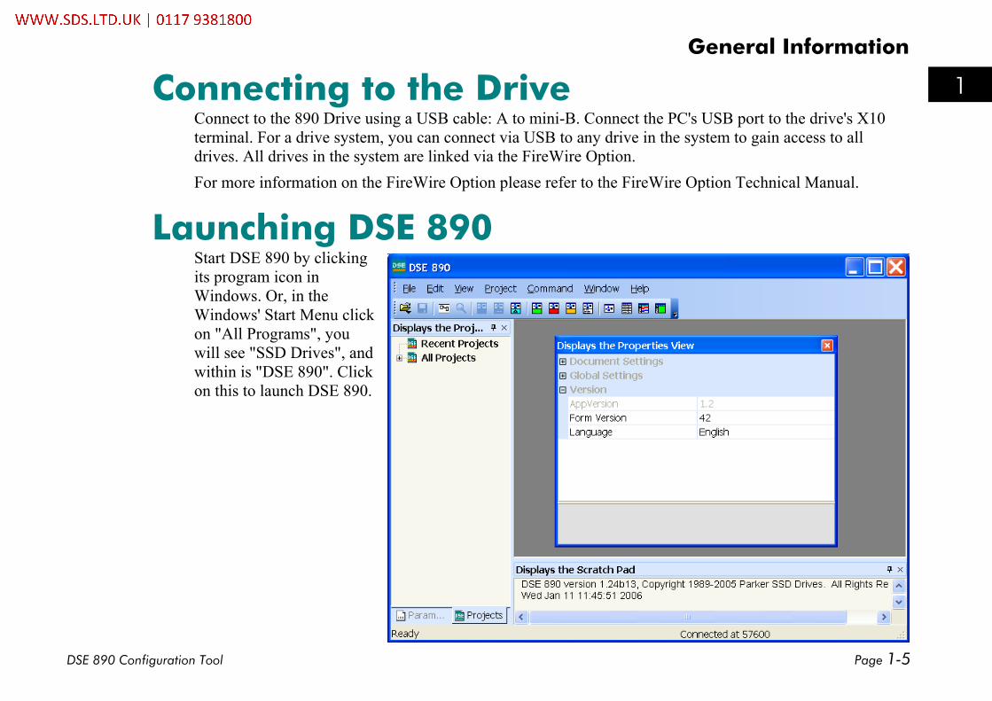
Connecting to the DriveConnect to the 890 Drive using a USB cable: A to mini-B. Connect the PC's USB port to the drive's X10terminal. For a drive system, you can connect via USB to any drive in the system to gain access to alldrives. All drives in the system are linked via the FireWire Option.For more information on the FireWire Option please refer to the FireWire Option Technical Manual.
Launching DSE 890Start DSE 890 by clickingits program icon inWindows. Or, in theWindows' Start Menu clickon "All Programs", youwill see "SSD Drives", andwithin is "DSE 890". Clickon this to launch DSE 890.


First Configuration
DSE 890 Configuration Tool Page 2-1
8
9
10
11
A
B
C
D
1
2
3
4
5
6
7
E
Chapter 2
Chapter 2 : First Configuration
How to create, modify and install a new configuration as well as going online.
♦ Creating a Configuration
♦ Modifying a Configuration
♦ Installing a Configuration
♦ Import/Export a Configuration
♦ The Online Configuration

First Configuration
Page 2-2 DSE 890 Configuration Tool
8
9
10
11
A
B
C
D
1
2
3
4
5
6
7
E
Creating a Configuration1. From the "File" menu, select "New". A Dialog will pop
up. Select a configuration, e.g. 890 Volts/Hertz, andclick "OK"
2. When prompted, enter a new configuration name,e.g. "L890_1", and click "OK".

First Configuration
DSE 890 Configuration Tool Page 2-3
8
9
10
11
A
B
C
D
1
2
3
4
5
6
7
E
3. Here is your first configuration L890_1*.
4. Save the configuration by clicking on File/Save or the Save icon, or select "Save" from the "File" menu.This will create a new revision of the configuration, revision 1. The asterisk "*" against the name willdisappear.

First Configuration
Page 2-4 DSE 890 Configuration Tool
8
9
10
11
A
B
C
D
1
2
3
4
5
6
7
E
Modifying a ConfigurationA configuration can be modified by editing blocks and links, and by inserting or deleting blocks.
Editing BlocksYou can view the contents of any function block in theconfiguration by double-clicking the icon for the block.For example, double click on "AN IN 3" will open theanalog input function block 3.Where a parameter can be edited, click on the relevantsub-menu to display the options (for enumerated andboolean parameters), or edit the displayed numericvalue directly on the screen by clicking on the value.When you have finished editing the block select "OK"to exit the block, otherwise select "Cancel" to exit theblock and disregard any changes you may have made.When you make any changes, save the configuration byclicking on the Save icon , or "File Save". This willremove the asterisk ( * ) against the configuration name.
Editing LinksA link transfers the value of anoutput parameter to an inputparameter of another (or thesame) block.

First Configuration
DSE 890 Configuration Tool Page 2-5
8
9
10
11
A
B
C
D
1
2
3
4
5
6
7
E
Links are made by connecting an output to an input, in that order.
To make a link
Hover the cursor over the output line until the cursor changes to an "x". At thispoint, click and hold the mouse button. Now stretch the red link to the inputline. When the link turns green, you have a possible connection. To make theconnection, let go of the mouse button.
To delete a link Click on the line. It will turn purple. Press the Delete key on your keyboard.
To reshape a link line Click on the line and hold the mouse button. The line will turn purple. Now youcan drag any part of the line in any direction.
Inserting New Function BlocksYou can insert any number of new function blocks into the Application. For example:Click on the Block menu at the top of the screen.1. Move the cursor down to select "Logic" and select "Counter".2. Click to attach the block icon to the cursor. Move the icon to where you want on the screen. Click again
to release the icon.3. To insert another of these blocks you can repeat the process or just Copy and Paste the original using the
Edit menu at the top of the page. (The standard Ctrl+C, Ctrl+V and Ctrl+X also apply).
Note For further details of all function blocks, refer to the 890 Engineering Reference manual, Appendix D.Motor Control Block details are available in DSE 890 by right-clicking a function block in the MotorControl Block pane and selecting "Help".
Deleting Function BlocksSelect a block and press the "Delete" key. This will delete the block.

First Configuration
Page 2-6 DSE 890 Configuration Tool
8
9
10
11
A
B
C
D
1
2
3
4
5
6
7
E
Editing the Motor Control BlockDouble-click the Motor Control Block. A new window will display the motor control block diagram.

First Configuration
DSE 890 Configuration Tool Page 2-7
8
9
10
11
A
B
C
D
1
2
3
4
5
6
7
E
Connecting Parameters to the ApplicationIf a motor control block has to be written to or read from the application, Inputs and Outputs can be addedto the Motor Control block diagram, respectively.
For example, to add a new input parameter called "REVERSE",open the Motor Control Block diagram, add a new input from theBlock menu, then rename it to "REVERSE" (shown connected toREFERENCE /REMOTE REVERSE).
On exiting, the motor Control Macro the additional input parameter"SETPOINT" will automatically appear on the Motor Control block asshown on the right.

First Configuration
Page 2-8 DSE 890 Configuration Tool
8
9
10
11
A
B
C
D
1
2
3
4
5
6
7
E
Installing a Configuration in a DriveOnce you have created your own configuration, you are in a position to install it in the drive. Select"Command Install At Selected" to install the currently opened configuration into a drive.The installation is confirmed by theScratch Pad message.The configuration is now installed intoyour drive.
AutotuneThe configuration must be closed:
1. Trigger Autotune in the drive (via the MMI) and wait for it to be completed.2. Select File Update; this will update the parameters in DSE's copy of the configuration.
This will ensure that your DSE 890 configuration reflects exactly the state of the drive.
Import/Export a ConfigurationSelect " File Export" in order to save a configuration at any location. This exported configuration can beimported into DSE on another computer by using "File Import.
The Online ConfigurationOpening the Default Configuration Online
If you did not install a configuration in the drive, select " File Open Online " or simply press "F9" to openthe default, shipping configuration in online mode.

First Configuration
DSE 890 Configuration Tool Page 2-9
8
9
10
11
A
B
C
D
1
2
3
4
5
6
7
E
Opening a New Configuration OnlineAt this point, your configuration should be installed in the drive. Now, select "Command Go Online" andthe configuration will be opened in online mode. Alternatively, you can select "File Open Online", orsimply hit "F9".
Working OnlineThe ONLINE configuration window looks the same as an OFFLINEversion, but has some extra features. Note that you cannot remove oradd blocks and links in online mode.When you hover the cursor over the output of a block, the cursor willchange to the shape of a "cross". Shift-click puts the parameter intothe Monitor List. To read the value in the function block and thescratchpad, just click. DSE 890 will get and display the actual value from the drive.
The Scratch pad will become visible and will display the retrieved value. The same happens if you click onan input of a block while holding the "SHIFT" key.
If you want to change an input value of a functionblock, simply click on the block input while holdingdown the "CTRL" key. This will bring up a dialogprompting for the value to be set. For instance, clickingon AN IN 3 : SCALE while holding the CTRL key willopen the following dialog.


DSE 890 Tools
DSE 890 Configuration Tool Page 3-1
8
9
10
11
A
B
C
D
1
2
3
4
5
6
7
E
Chapter 3
Chapter 3 : DSE 890 Tools
An explanation of the DSE 890 tools for working on configurations.
IntroductionThe Properties ViewThe Scratch PadThe Projects ViewThe Parameters ViewThe Configuration View
The ONLINE Configuration
• The Module List
• Scratch Pad
• The Monitor List
• The Chart Recorder
• The Oscilloscope
DSE 890 Tools
Page 3-2 DSE 890 Configuration Tool
8
9
10
11
A
B
C
D
1
2
3
4
5
6
7
E
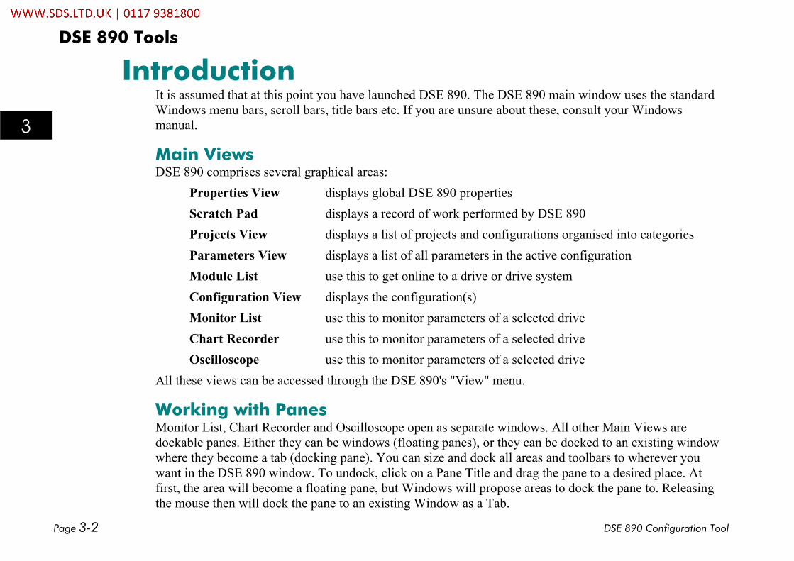
IntroductionIt is assumed that at this point you have launched DSE 890. The DSE 890 main window uses the standardWindows menu bars, scroll bars, title bars etc. If you are unsure about these, consult your Windowsmanual.
Main ViewsDSE 890 comprises several graphical areas:
Properties View displays global DSE 890 propertiesScratch Pad displays a record of work performed by DSE 890Projects View displays a list of projects and configurations organised into categoriesParameters View displays a list of all parameters in the active configurationModule List use this to get online to a drive or drive systemConfiguration View displays the configuration(s)Monitor List use this to monitor parameters of a selected driveChart Recorder use this to monitor parameters of a selected driveOscilloscope use this to monitor parameters of a selected drive
All these views can be accessed through the DSE 890's "View" menu.
Working with PanesMonitor List, Chart Recorder and Oscilloscope open as separate windows. All other Main Views aredockable panes. Either they can be windows (floating panes), or they can be docked to an existing windowwhere they become a tab (docking pane). You can size and dock all areas and toolbars to wherever youwant in the DSE 890 window. To undock, click on a Pane Title and drag the pane to a desired place. Atfirst, the area will become a floating pane, but Windows will propose areas to dock the pane to. Releasingthe mouse then will dock the pane to an existing Window as a Tab.

DSE 890 Tools
DSE 890 Configuration Tool Page 3-3
8
9
10
11
A
B
C
D
1
2
3
4
5
6
7
E
The Properties ViewThe Properties view allows you to configure the behaviour of DSE 890 through parameters organized into atree. Initially, the Properties View will display all items in the Version section.
VersionAppVersionThe application version is displayed and can not be changed.
Form VersionThis displays the version of the pane layout and can be used toreset the layout to the default settings. To reset the pane layoutto its shipping version, select "Form Version" and set its valueto 0. Then exit DSE 890. After launching DSE 890, the panelayout is reset to its default.
LanguageSelect your language from the "Language" item.
Document SettingsThese settings refer to a configuration's block diagram and howit is displayed: Snap to Grid, Grid Size, Block (colors forselected, advanced and high performance blocks), Connections(colors for connected, unconnected and selected connections).
DSE 890 Tools
Page 3-4 DSE 890 Configuration Tool
8
9
10
11
A
B
C
D
1
2
3
4
5
6
7
E
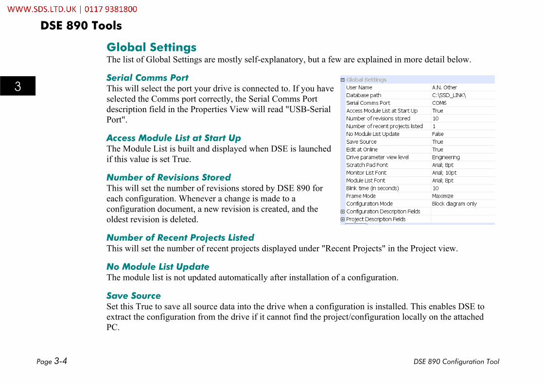
Global SettingsThe list of Global Settings are mostly self-explanatory, but a few are explained in more detail below.
Serial Comms PortThis will select the port your drive is connected to. If you haveselected the Comms port correctly, the Serial Comms Portdescription field in the Properties View will read "USB-SerialPort".
Access Module List at Start UpThe Module List is built and displayed when DSE is launchedif this value is set True.
Number of Revisions StoredThis will set the number of revisions stored by DSE 890 foreach configuration. Whenever a change is made to aconfiguration document, a new revision is created, and theoldest revision is deleted.
Number of Recent Projects ListedThis will set the number of recent projects displayed under "Recent Projects" in the Project view.
No Module List UpdateThe module list is not updated automatically after installation of a configuration.
Save SourceSet this True to save all source data into the drive when a configuration is installed. This enables DSE toextract the configuration from the drive if it cannot find the project/configuration locally on the attachedPC.

DSE 890 Tools
DSE 890 Configuration Tool Page 3-5
8
9
10
11
A
B
C
D
1
2
3
4
5
6
7
E
Edit at OnlineTrue if a configuration can be edited in online mode.
Drive Parameter View LevelSet this to view Drive Parameters of a certain level. Each parameter has a viewing level attributed to it,from "Operator" (basic operating parameters) to "Engineering" (high-end parameters primarily used bySSD engineers).
Frame ModeThis will set how a configuration's block diagram is displayed: maximized or in a "frame per configuration"block diagram.
Configuration ModeThis will add a list of parameters to the Configuration View when set to "Block Diagram and ParameterTree". The configuration view displays only the block diagram if this mode is set to "Block Diagram only".
Configuration Description FieldsYou can set up to 6 description fields here. Double-click the required field (e.g. Field 1). Enter your newtext. These fields can be referenced in a Form that can be inserted in to a Configuration : Insert Form.
Project Description FieldsYou can set up to 9 description fields here. Double-click the required field (e.g. Field 1). Enter your newtext. These fields can be referenced in a Form that can be inserted in to a Configuration : Insert Form.

DSE 890 Tools
Page 3-6 DSE 890 Configuration Tool
8
9
10
11
A
B
C
D
1
2
3
4
5
6
7
E
The Scratch PadThe Scratch Pad reports the activities of DSE 890 to the user. When DSE 890 is started it will display theDSE 890 version, the date, the user name and company DSE 890 is licensed to, together with the databaseID. You can enter today's date and time into the Scratch Pad: "Edit Paste Time".

DSE 890 Tools
DSE 890 Configuration Tool Page 3-7
8
9
10
11
A
B
C
D
1
2
3
4
5
6
7
E
The Projects ViewThe Projects View displays a tree view of Categories, Projects and Configurations.A DSE 890 Project can contain one or more Configurations. Often a projectcontains many configurations to control a complete system (e.g. a group of DSE890 drives supplied by SSD Drives for controlling the motors of a printing press).You can also create configurations for any SSD Drives module supported by DSE890.DSE 890 Development only: By storing all related Projects in a Category you cankeep them in a logical grouping.
Project View Context MenusRight-clicking a Configuration, Project or Category displays a menu of actions.
Recent Projects/All Projects MenuRight-clicking the "All Projects" or "Recent Projects" displays a menu ofactions to the projects collection.Note that if a Category does not contain a Project, the category name isnot stored in the SSD LINK database of projects.The Projects View displays all projects under the "All Projects" item, andthe recently worked on projects under the "Recent Projects" item. Youcan change the number of recent projects displayed in the tree(View Properties Global Settings Number of Recent Projects Listed).

DSE 890 Tools
Page 3-8 DSE 890 Configuration Tool
8
9
10
11
A
B
C
D
1
2
3
4
5
6
7
E
Category Menu (DSE 890 Development)Right-clicking a Category displays a menu of actions applying to acategory.This menu allows you to create a new project in a Category.The creation of a new project will be reported in the Scratchpad.
Project MenuRight-clicking a Project displays a menu of actions applying to aproject.A few of these actions need explanation:
New Configuration -brings up a dialog which allows you toselect a default configuration, e.g. Voltz/Hertz, and prompts for aname.Compact Project - executes "Compact Configuration" for thewhole project. Refer to "Configuration Menu" above.Upgrade Project - executes "Upgrade Configuration" for thewhole project. Refer to "Configuration Menu" above.Update Project - executes "Update Configuration" for the wholeproject. Refer to "Configuration Menu" above.Read Only - this toggles the read-only flag of the project.History - displays the revision history of all configurations of the project.

DSE 890 Tools
DSE 890 Configuration Tool Page 3-9
8
9
10
11
A
B
C
D
1
2
3
4
5
6
7
E
Configuration MenuRight-clicking a configuration displays a menu of actionsapplying to a configuration.A few of these actions need explanation:
Compact Configuration - this deletes all old revisions ofthis configuration that are not installed.Upgrade Configuration - upgrades all blocks in aconfiguration to use the latest revision of the block.Update Configuration - updates the configuration usinguploaded values from the drive.Read Only - this toggles the read-only flag of theconfiguration.History - displays the revision history of the configuration.

DSE 890 Tools
Page 3-10 DSE 890 Configuration Tool
8
9
10
11
A
B
C
D
1
2
3
4
5
6
7
E
Project View ActionsSimilar to MicroSoft Explorer, you can navigate in the projects tree and perform certain actions.
Moving a ProjectGrab a project by selecting it and holding down the mouse button, then drag the project to a differentcategory. Releasing the project item then will move the project category.
Renaming an ItemSelect a category, project or configuration, click a second time on it. The item will become editable. Nowyou can change its name. Hitting enter will exit the edit mode and change the name.
Opening a ConfigurationDouble-click on a configuration in the Projects window to open the configuration. This may be either in itsown window (Normal mode), or maximized as a tab. You can change this behaviour in the Properties View.
DSE 890 Tools
DSE 890 Configuration Tool Page 3-11
8
9
10
11
A
B
C
D
1
2
3
4
5
6
7
E
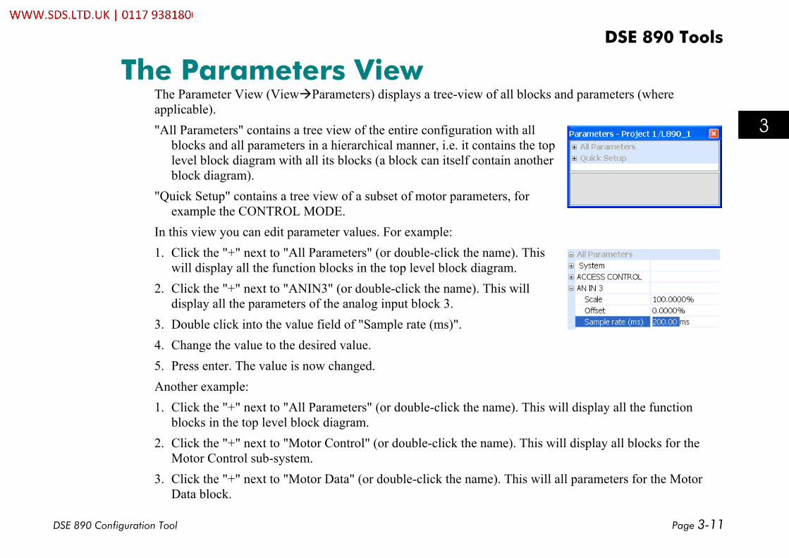
The Parameters ViewThe Parameter View (View Parameters) displays a tree-view of all blocks and parameters (whereapplicable)."All Parameters" contains a tree view of the entire configuration with all
blocks and all parameters in a hierarchical manner, i.e. it contains the toplevel block diagram with all its blocks (a block can itself contain anotherblock diagram).
"Quick Setup" contains a tree view of a subset of motor parameters, forexample the CONTROL MODE.
In this view you can edit parameter values. For example:1. Click the "+" next to "All Parameters" (or double-click the name). This
will display all the function blocks in the top level block diagram.2. Click the "+" next to "ANIN3" (or double-click the name). This will
display all the parameters of the analog input block 3.3. Double click into the value field of "Sample rate (ms)".4. Change the value to the desired value.5. Press enter. The value is now changed.Another example:1. Click the "+" next to "All Parameters" (or double-click the name). This will display all the function
blocks in the top level block diagram.2. Click the "+" next to "Motor Control" (or double-click the name). This will display all blocks for the
Motor Control sub-system.3. Click the "+" next to "Motor Data" (or double-click the name). This will all parameters for the Motor
Data block.

DSE 890 Tools
Page 3-12 DSE 890 Configuration Tool
8
9
10
11
A
B
C
D
1
2
3
4
5
6
7
E
4. Click the POWER to allow editing. You will see theparameter reference number displayed, the fullparameter path as accessed in the block diagramhierarchy, and if applicable, the maximum/minimumvalues and units.
5. Click into the value field to change the parameter value.
The Parameters View provides a convenient means tochange parameter values throughout the configuration.
Note that all firmware parameters can be referenced by aparameter reference (Pref) number in the format:
BLOCKNUMBER.PARAMETERNUMBERYou can read the parameter reference in the ParametersView. For instance, the Parameter Reference for "MOTORDATA/POWER " would be "27.2".

DSE 890 Tools
DSE 890 Configuration Tool Page 3-13
8
9
10
11
A
B
C
D
1
2
3
4
5
6
7
E
The Configuration ViewThe default configuration for the 890 is shown below. It contains the Motor Control block, the functionblocks required by the default Application and their links.
DSE 890 Tools
Page 3-14 DSE 890 Configuration Tool
8
9
10
11
A
B
C
D
1
2
3
4
5
6
7
E
Modifying the ConfigurationA configuration can be modified by changing parameter values of existing blocks, adding new blocks, oradding/deleting links between function blocks. In addition, graphical elements can be added to improve theunderstanding of your configuration.
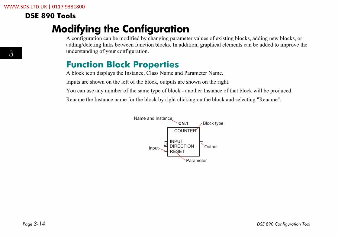
Function Block PropertiesA block icon displays the Instance, Class Name and Parameter Name.Inputs are shown on the left of the block, outputs are shown on the right.You can use any number of the same type of block - another Instance of that block will be produced.Rename the Instance name for the block by right clicking on the block and selecting "Rename".
COUNTER
INPUTDIRECTIONRESET
CN.1Name and Instance
InputU Output
Block type
Parameter
DSE 890 Tools
DSE 890 Configuration Tool Page 3-15
8
9
10
11
A
B
C
D
1
2
3
4
5
6
7
E
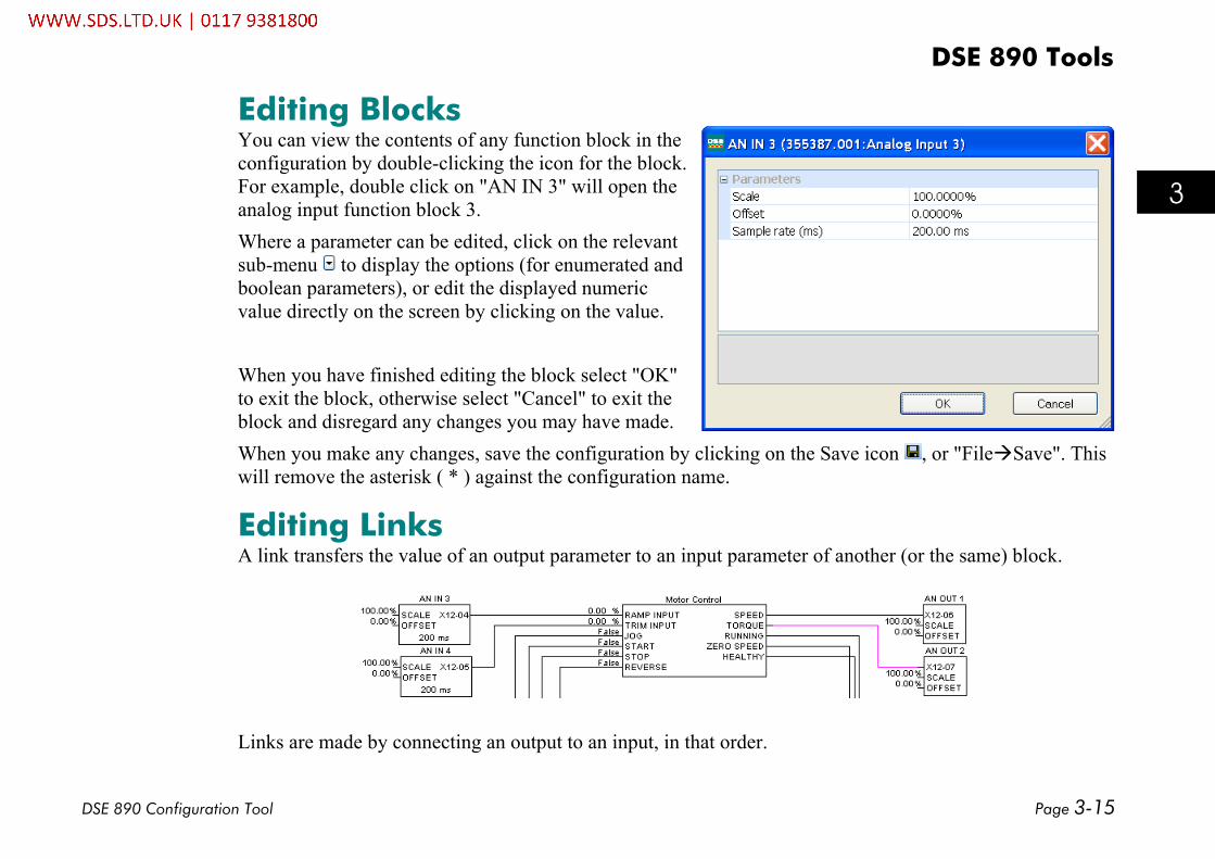
Editing BlocksYou can view the contents of any function block in theconfiguration by double-clicking the icon for the block.For example, double click on "AN IN 3" will open theanalog input function block 3.Where a parameter can be edited, click on the relevantsub-menu to display the options (for enumerated andboolean parameters), or edit the displayed numericvalue directly on the screen by clicking on the value.
When you have finished editing the block select "OK"to exit the block, otherwise select "Cancel" to exit theblock and disregard any changes you may have made.When you make any changes, save the configuration by clicking on the Save icon , or "File Save". Thiswill remove the asterisk ( * ) against the configuration name.
Editing LinksA link transfers the value of an output parameter to an input parameter of another (or the same) block.
Links are made by connecting an output to an input, in that order.

DSE 890 Tools
Page 3-16 DSE 890 Configuration Tool
8
9
10
11
A
B
C
D
1
2
3
4
5
6
7
E
To make a link
Hover the cursor over the output line until the cursor changes to an "x". At thispoint, click and hold the mouse button. Now stretch the red link to the input line.When the link turns green, you have a possible connection. To make theconnection, let go of the mouse button.
To delete a link Click on the line. It will turn purple. Press the Delete key on your keyboard.
To reshape a link lineClick on the line and hold the mouse button. The line will turn purple. Now youcan drag any part of the line in any direction. Click away from the line todeselect it. The line will turn black.
To split a link
This allows you to split a link on a page or between different pages of theconfiguration.To split a link on a page:
Make the link (as above). Double click on the link to select it. It will turnpurple and a message box will appear. Confirm to split the connection.The link will be split with the relevant text pointers.
To split a link between different pages:Make the link (as above) but, while holding the mouse button, click on"►" . This will open the next page and allow you toconnect to an input on that page. The link will be made with the relevanttext pointers.

DSE 890 Tools
DSE 890 Configuration Tool Page 3-17
8
9
10
11
A
B
C
D
1
2
3
4
5
6
7
E
Inserting New Function BlocksYou can insert any number of new function blocks into the Application. For example:Click on the Block menu at the top of the screen.4. Move the cursor down to select "Logic" and select "Counter".5. Click to attach the block icon to the cursor. Move the icon to where you want on the screen. Click again
to release the icon.6. To insert another of these blocks you can repeat the process, or just Copy and Paste the original using
the Edit menu at the top of the page. (Ctrl+C to copy, Ctrl+V to paste, and Ctrl+X to cut selected textalso apply).
Note For further details of all function blocks, refer to the 890 Engineering Reference manual, Appendix D.Motor Control Block details are available in DSE 890 by right-clicking a function block in the MotorControl Block pane and selecting "Help".
Deleting Function BlocksTo delete a block, select the block and press the "Delete" key.

DSE 890 Tools
Page 3-18 DSE 890 Configuration Tool
8
9
10
11
A
B
C
D
1
2
3
4
5
6
7
E
Macro BlocksAn important feature of DSE 890 is the use of the Macro Block. These blocks can be used to run a portionof the application. Because the blocks can be layered, the entire application can be organised in ahierarchical and structured manner. (The Motor Control block is in fact a Macro block).To insert a Macro block, go to the Block menu and select "Macro".
As a result, a new Macro block will be added to your configuration. Double click on the block to open thenew, empty diagram. You can add blocks (including further Macro blocks) and links as usual. In addition,you may add input and/or output blocks from the "Blocks" menu using "Input" and "Output" respectively.Adding one input and one output and connecting them together would create the following diagram. Notethat the input and output will automatically appear as additional ticks on the Macro block icon.

DSE 890 Tools
DSE 890 Configuration Tool Page 3-19
8
9
10
11
A
B
C
D
1
2
3
4
5
6
7
E
Network I/O BlocksWhen in the main, or top level diagram, selecting "Input" or "Output from the "Blocks" menu will create aNetwork input or output respectively. You must provide the node ID of the source as well as a slot number,which acts as unique identifier.
The Description field will become the input/output block name (Instance).
Connecting Parameters to the ApplicationRefer to "Connecting Parameters to the Application" on page 7.

DSE 890 Tools
Page 3-20 DSE 890 Configuration Tool
8
9
10
11
A
B
C
D
1
2
3
4
5
6
7
E
Inserting and Creating FormsDSE allows to add forms to a configuration. Either you can ad an existing form through the menu "Insert ->Forms -> Name of the form to be inserted", or you can create a new form.If you want to create a new Form, select menu "Insert -> Forms -> Create …" which will pop up a dialog:
After entering a name, e.g. "Form 1" and selecting OK, an empty Form will be created.
Using the Drawing Toolbar you can add any drawing element.

DSE 890 Tools
DSE 890 Configuration Tool Page 3-21
8
9
10
11
A
B
C
D
1
2
3
4
5
6
7
E
The ONLINE ConfigurationNote You cannot remove or add blocks and links in ONLINE mode.
To go ONLINE, refer to page 2-8.The ONLINE configuration window has "ONLINE" displayed in the title, but otherwise the window looksthe same as the OFFLINE version, but it does have some extra features.Move your cursor over the "tick" of the parameter in the function box and the cursor will change to an "X".Now you can:
• Click the input or output of a block to display theactual value from the drive in the Scratchpad.
• SHIFT-click the output of a block to add thatparameter to the Monitor List.
• CTRL-click the input of a block to change the parameter value.This will bring up a dialog prompting for the value to be set.
• Right-click a parameter to display a menu of actions applying to theparameter (right-clicking a parameter in the Parameters View has the same effect):
Get Display the parameter value in the Scratchpad.Monitor Add this parameter to the Monitor ListChart Add this parameter to the Chart RecorderScope Add this parameter to the Oscilloscope.
Note that in all cases the Scratchpad will display the latest value.

DSE 890 Tools
Page 3-22 DSE 890 Configuration Tool
8
9
10
11
A
B
C
D
1
2
3
4
5
6
7
E
The Module ListThis displays all the modules that are connected to the PC and allows you to select the drive to go ONLINEwith. Select "View Module List". By default it will appear in the bottom right of the screen.If you have connected a single drive, then this drive will be seen in the module list.
If you have a drive system connected together using the FireWire Option(s), the drive your PC is connectedto directly will be the first in the list. It will have the network address of 0001. The first module in this listwill automatically be selected and be marked with an Asterisk.
Note The Projects View will display an install flag " " against a configuration to indicate the configurationin use by the selected module.
If your drive is not displaying in the Module List:
• Check the connection between the PC and the connected drive
• Check the FireWire cable connections if a system drive
• Check the FireWire Option is inserted correctly into the front of each system drive

DSE 890 Tools
DSE 890 Configuration Tool Page 3-23
8
9
10
11
A
B
C
D
1
2
3
4
5
6
7
E
Module List InformationAddress Displays the Net Address for the connected drive (Edit Net Address)Name Displays the name of the configuration in use by the selected driveLibrary Displays the library name for the configurationStatus Displays the status of the selected driveCPU% Indicates the amount of CPU activity, or how busy the microprocessor was since the last
execution of a module list. This information is also available if a "Command Get Info" isperformed.
Heap % Displays how much static RAM (SRAM) the module's CPU has used since the module lastentered the OK state and began executing the installed configuration. This information is alsoavailable if a "Command Get Info" is performed.
Message/s (Messages/second) This is the average number of messages per second of network traffic theselected module receives. This information is also available if a "Command Get Info" isperformed.
Errors This is the sum of fragments, CRC Errors and overrunsFragments: Messages received by the module that are shorter than the 72 bitsrequired.CRC Errors (Cyclic Redundancy Check word) Bad checksums on messages receivedinto the Link module.Overruns: Messages received by the Link module are longer than the 72 bits required
This information is also available if a "Command Get Info" is performed.The Fragments, CRC errors and Overruns values should all be zero. On occasion you maysee 1 or 2, but normally the numbers in these registers should be zero. If they continuallycount up, there may be a problem with the network.

DSE 890 Tools
Page 3-24 DSE 890 Configuration Tool
8
9
10
11
A
B
C
D
1
2
3
4
5
6
7
E
Scratch Pad Module InformationSelecting a module in the Module list, then selecting "Command Get Info" will enter "ModuleInformation" into the Scratch Pad.
Serial Number Displays the serial number for the selected driveProject Displays the "project number: category name/project name" for the selected driveConfiguration Displays the name of the configuration in use by the selected driveType Displays information about the type of module selected including library
informationModification Displays the revision number installedPermanent Address Displays the permanent network addressWorking Address Displays the working network addressPersistents Used Amount of persistent memory used

DSE 890 Tools
DSE 890 Configuration Tool Page 3-25
8
9
10
11
A
B
C
D
1
2
3
4
5
6
7
E
CPU Used Indicates the amount of CPU activity, or how busy the microprocessor was sincethe last execution of a module list. This information is also available in the ModuleList
Heap Used Displays how much static RAM (SRAM) the module's CPU has used since themodule last entered the OK state and began executing the installed configuration.This information is also available in the Module List
Messages/s (Messages/second) This is the average number of messages per second of networktraffic the selected module receives. This information is also available in theModule List
Status Displays the status of the selected drive

DSE 890 Tools
Page 3-26 DSE 890 Configuration Tool
8
9
10
11
A
B
C
D
1
2
3
4
5
6
7
E
The Monitor ListThe Monitor List displays all the drive parameters that you aremonitoring and continuously gets updated values from thedrive.
The Monitor List ToolbarThe toolbar contains several buttons:
Open saved Monitor List configuration from a file.Save Monitor List configuration to a file.Toggle the Monitor List to be on top.Start recording to a file.Stop recording.Change the font of the items in the monitor list.
DSE 890 Tools
DSE 890 Configuration Tool Page 3-27
8
9
10
11
A
B
C
D
1
2
3
4
5
6
7
E
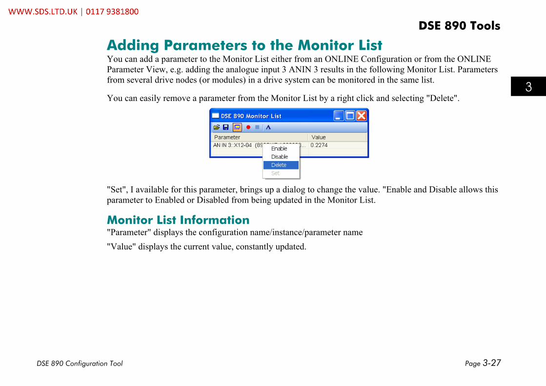
Adding Parameters to the Monitor ListYou can add a parameter to the Monitor List either from an ONLINE Configuration or from the ONLINEParameter View, e.g. adding the analogue input 3 ANIN 3 results in the following Monitor List. Parametersfrom several drive nodes (or modules) in a drive system can be monitored in the same list.
You can easily remove a parameter from the Monitor List by a right click and selecting "Delete".
"Set", I available for this parameter, brings up a dialog to change the value. "Enable and Disable allows thisparameter to Enabled or Disabled from being updated in the Monitor List.
Monitor List Information"Parameter" displays the configuration name/instance/parameter name"Value" displays the current value, constantly updated.

DSE 890 Tools
Page 3-28 DSE 890 Configuration Tool
8
9
10
11
A
B
C
D
1
2
3
4
5
6
7
E
The Chart RecorderThe Chart Recorder displays the values of the selected parameter(s) and continuously gets updated valuesfrom the drive.Here is a typical chart. It shows one parameter, analogue input 3 AN IN 3 .

DSE 890 Tools
DSE 890 Configuration Tool Page 3-29
8
9
10
11
A
B
C
D
1
2
3
4
5
6
7
E
The Chart Recorder ToolbarThe toolbar contains several buttons:
Open saved oscilloscope data or configuration from a file.Save captured oscilloscope data and configuration to a file.Print oscilloscope plot.Toggle the Chart Recorder to be on top.Display/Hide the property grid.Restart data acquisition.Pause data acquisition.Start recording to a file.Stop recording.
Adding Parameters to the Chart RecorderYou can add a parameter to the chart recorder either from the ONLINE Configuration or from the ONLINEParameter View.Parameters from several drive nodes (or modules) in a drive system can be charted on the same chart.
Setting-up the Chart RecorderThe Chart Recorder displays menus for Settings and Channels.

DSE 890 Tools
Page 3-30 DSE 890 Configuration Tool
8
9
10
11
A
B
C
D
1
2
3
4
5
6
7
E
Settings"Settings" displays the settings for how the chart recorder displays theinformation.
Time base [s] : This is the time period shown by the chart (x axis)Chart Mode : When False the chart redraws at the end of the time range; when True the
chart scrolls continuouslyY axis automatic : When False the Y axis is set by "Y axis min" and "Y axis max"; when True
the Y axis is set automaticallyY axis min : Sets the minimum Y axis for the chartY axis max : Sets the maximum Y axis for the chartBackground color : Background color of the chartGrid color : Foreground color of the chart
DSE 890 Tools
DSE 890 Configuration Tool Page 3-31
8
9
10
11
A
B
C
D
1
2
3
4
5
6
7
E
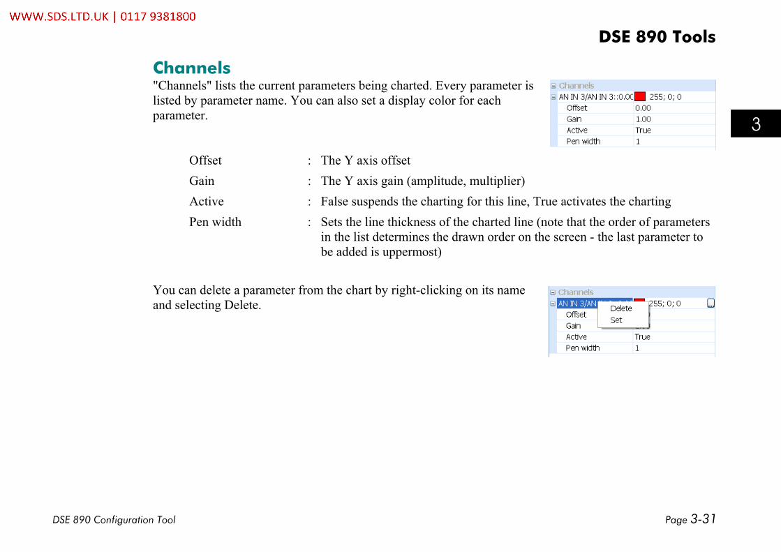
Channels"Channels" lists the current parameters being charted. Every parameter islisted by parameter name. You can also set a display color for eachparameter.
Offset : The Y axis offsetGain : The Y axis gain (amplitude, multiplier)Active : False suspends the charting for this line, True activates the chartingPen width : Sets the line thickness of the charted line (note that the order of parameters
in the list determines the drawn order on the screen - the last parameter tobe added is uppermost)
You can delete a parameter from the chart by right-clicking on its nameand selecting Delete.

DSE 890 Tools
Page 3-32 DSE 890 Configuration Tool
8
9
10
11
A
B
C
D
1
2
3
4
5
6
7
E
The OscilloscopeThe Oscilloscope will set-up a real-time data acquisition facility inside the drive firmware, wait for data tobe ready, retrieve the data and display it. This is a tool to capture and display fast signals from external orinternal triggers.Shown below is atypical chart,"FEEDBACKS/SPEEDFBK %" withparameter reference"70.6".
All parameter valuesare normalised into 10divisions in the maindisplay area. Time is bedisplayed inmilliseconds."Measurement", at thebottom of the screen,displays measuredvalues such asminimum, maximumand RMS. In additionthis is the display areafor the cursors.

DSE 890 Tools
DSE 890 Configuration Tool Page 3-33
8
9
10
11
A
B
C
D
1
2
3
4
5
6
7
E
The Oscilloscope ToolbarThe toolbar contains several buttons:
Open saved oscilloscope data or configuration from a file.Save captured oscilloscope data and configuration to a file.Print oscilloscope plot.Copy oscilloscope plot to clipboardToggle the Oscilloscope to be on top.Display/Hide the property grid.Download the oscilloscope set-up to the drive.Manually hold the data if no trigger has occurred.Stop polling for the status.Upload the data once available for upload.
Adding Parameters to the OscilloscopeYou can add a parameter to the Oscilloscope either from an ONLINE configuration or from the ONLINEParameter View, e.g. adding the speed feedback in rpm from MOTOR CONTROL / FEEDBACKS /SPEED FBK RPM result in the following oscilloscope view.Note that only firmware parameters can be scoped.

DSE 890 Tools
Page 3-34 DSE 890 Configuration Tool
8
9
10
11
A
B
C
D
1
2
3
4
5
6
7
E
Another way to add parameters to the oscilloscope is to right-click on "Nodes", which will bring up a menuwith three choices:
Add Address Add a physical address in the firmware to scopeAdd Special Add a special parameter from a pick listAdd Pref Add a parameter reference number
In all three cases you will be prompted to enter the modulenode number with a dialog.
• In the case of Add Address, you will be prompted to entera memory address as a hexadecimal number, e.g. 0x0010.
• In the case of Add Special, a pick list will appear, showopposite. This pick list will depend on the type ofconfiguration, e.g. Permanent Magnet Motorconfiguration will be different from a Volts/Hertz one.
• In the case of Add Pref, a dialog will prompt for aparameter reference number, which expects the format:
BLOCKNUMBER.PARAMETERNUMBER

DSE 890 Tools
DSE 890 Configuration Tool Page 3-35
8
9
10
11
A
B
C
D
1
2
3
4
5
6
7
E
Setting-up the OscilloscopeThe Oscilloscope displays menus for Settings, Cursors and Nodes. The oscilloscope facility will do nothinguntil it is set-up.
Settings"Settings" displays the settings for how the oscilloscope displays theinformation.
Description : Description printed in the legendShow Legend : Show legend in plotTime Scale : Time scale on plot x axisCyclic Mode : Carry out data acquisition in a cyclic mannerBackground color : Background color of the scopeGrid color : Grid color of the scope
Cursors"Cursors" controls the cursors for X and Y axis.
Active : Select None, Horizontal, Vertical or both cursorsChannel : Select the channel the cursor should apply to

DSE 890 Tools
Page 3-36 DSE 890 Configuration Tool
8
9
10
11
A
B
C
D
1
2
3
4
5
6
7
E
Axes"Axes" are named axis for the plot that can be added by the user.Each plotted channel comes with its own axis. In order to group severalchannels into one axis, a named axis can be added and its minimum andmaximum values can be specified.
Maximum : Sets maximum value in the data display areaMinimum : Sets minimum value in the data display area
Nodes"Nodes" lists in hierarchical order the parameters to scope for each node.Once a parameter has been added to the scope, a node will be addedautomatically. The node name will be the name of the correspondingconfiguration.Each node entry will then contain a "Setup" item and a "Channels" item.

DSE 890 Tools
DSE 890 Configuration Tool Page 3-37
8
9
10
11
A
B
C
D
1
2
3
4
5
6
7
E
Setup"Setup" contains all the information to set up the dataacquisition facility in the drive.
Trace* Mode Hold Trace on Trigger, Start, Stop or FullTrigger Direction Falling, Rising or no triggerTrigger Source Pull down list of available parametersTrigger Value Numerical value of parameter to trigger onTrigger is Real Value If true the raw data are scaled.Trigger Location Location in % of the entire data sample where the trigger is expected.Sample Number Number of samples to be acquiredSample Rate Sample rate in period defined nextSample Period Sample period, either milliseconds, or on the fastest task in the firmware, the
pattern generator.
* The term "trace" is used as a synonym for "data acquisition".

DSE 890 Tools
Page 3-38 DSE 890 Configuration Tool
8
9
10
11
A
B
C
D
1
2
3
4
5
6
7
E
Channels"Channels" controls channel configuration and contains a"Channel" entry per parameter using the name of the parameter.This entry also sets a color for the parameter.
Type : Type can be either value, i.e. a real data type, or an integer.Active : False suspends the display and setup for this channel
True activates the display and setup.Axis : The Axis can be assigned automatically, manually with minimum and
maximum specified, or assigned to a named axis.Minimum : Sets minimum value in the data display areaMaximum : Sets maximum value in the data display areaPen width : Sets the line thickness of the charted.Comment : The comment added here will appear in the printed versionOffset : Sets the offset of the channelGain : Sets the gain of the channel
A parameter (channel) can easily be removed by a right click on theparameter and selecting "Delete".
DSE 890 Tools
DSE 890 Configuration Tool Page 3-39
8
9
10
11
A
B
C
D
1
2
3
4
5
6
7
E
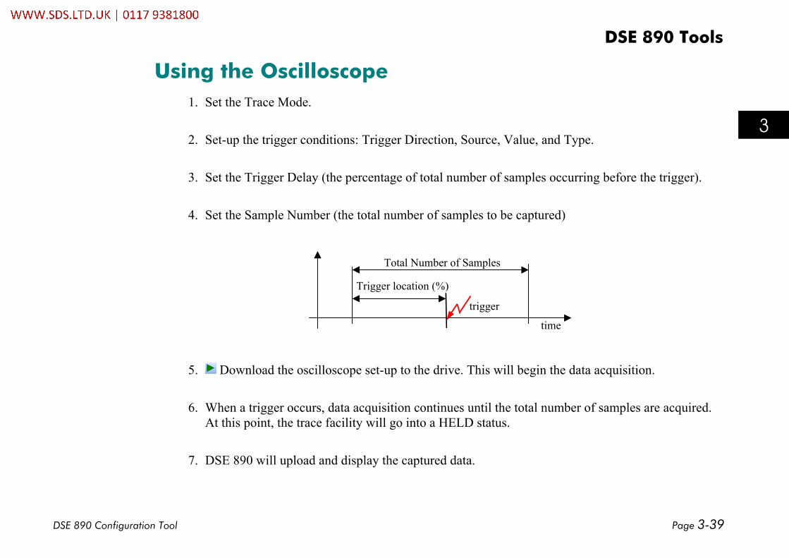
Using the Oscilloscope1. Set the Trace Mode.
2. Set-up the trigger conditions: Trigger Direction, Source, Value, and Type.
3. Set the Trigger Delay (the percentage of total number of samples occurring before the trigger).
4. Set the Sample Number (the total number of samples to be captured)
Trigger location (%)
Total Number of Samples
time
trigger
5. Download the oscilloscope set-up to the drive. This will begin the data acquisition.
6. When a trigger occurs, data acquisition continues until the total number of samples are acquired.At this point, the trace facility will go into a HELD status.
7. DSE 890 will upload and display the captured data.


How-To
DSE 890 Configuration Tool Page 4-1
8
9
10
11
A
B
C
D
1
2
3
4
5
6
7
E
9
10
11
A
B
C
D
7
Chapter 4
Chapter 3 : How-To
A quick list of common requirements and problems.
• How-To

How-To
Page 4-2 DSE 890 Configuration Tool
8
9
10
11
A
B
C
D
1
2
3
4
5
6
7
E
9
10
11
A
B
C
D
7
How-ToInstall a Configuration
If you have created your own configuration, you need to install it in the drive.There are two methods for installing a configuration:1. Select "Command Install At Selected" to install the currently opened configuration into a drive
selected in the Module List (a list of all drives that are connected to the PC).2. Select "Command Install At Address" to install the currently opened configuration at the Net
address for the drive (defined in the configuration, see XXX to change the net address.)The installation will be confirmed by a Scratch Pad message.Now the configuration is installed into yourdrive. You are now the owner of thisconfiguration. It cannot be edited byanother copy of DSE 890 without yourconsent.
Open a Configuration ONLINEDouble click on the selected module in the Module List to open the installed configuration into an ONLINEmode configuration window. For details on working with configurations please refer to Chapter 3: "Chapter3 : DSE 890 Tools".Unless a new configuration has been installed previously, the default configuration (890SHIP) will beopened. This configuration can be found in the Projects View under "All Projects/Public/Standalone".
How-To
DSE 890 Configuration Tool Page 4-1
8
9
10
11
A
B
C
D
1
2
3
4
5
6
7
E
9
10
11
A
B
C
D
7
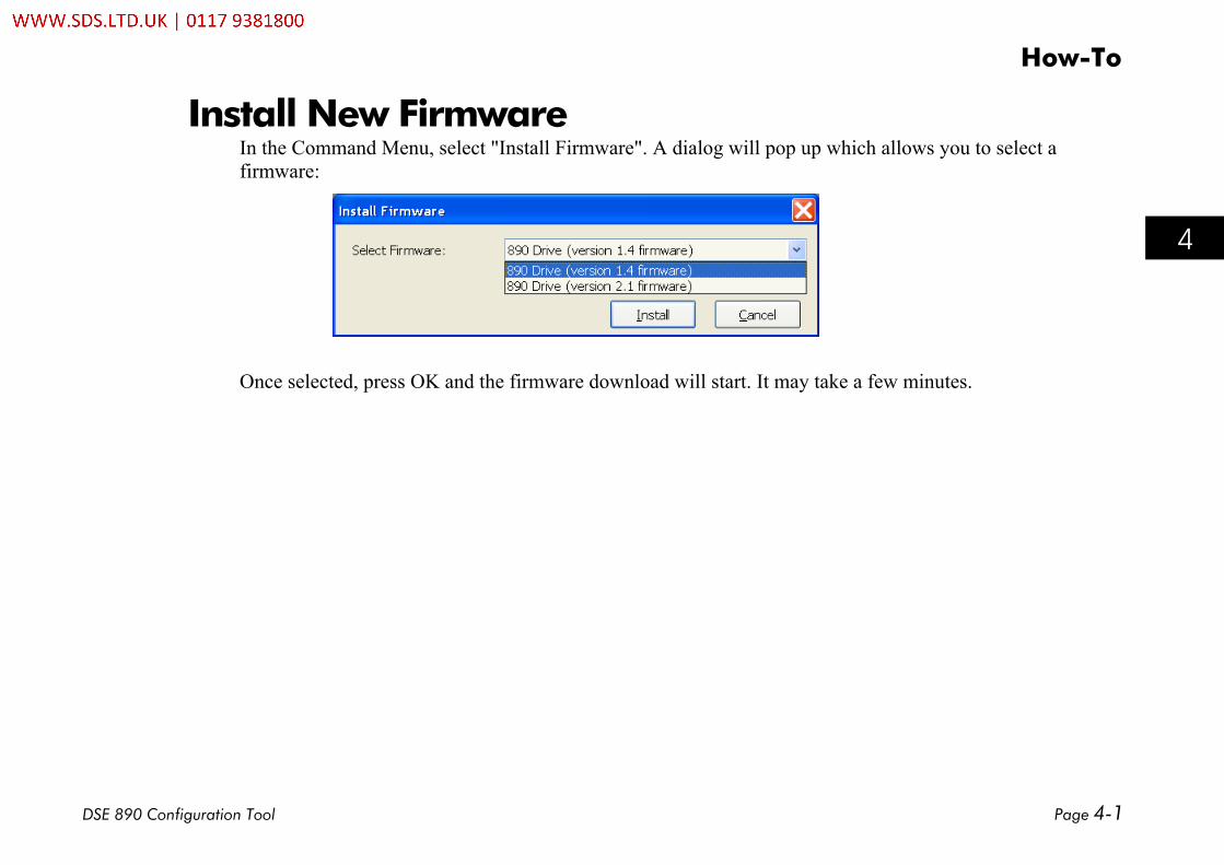
Install New FirmwareIn the Command Menu, select "Install Firmware". A dialog will pop up which allows you to select afirmware:
Once selected, press OK and the firmware download will start. It may take a few minutes.


Toolbars & Menus
DSE 890 Configuration Tool Page 5-1
8
1
2
3
4
5
6
E
9
10
11
A
B
C
D
7
Chapter 5
Chapter 5 : Toolbars & Menus
A listing of all DSE 890 toolbars and menus.
♦ Toolbars
♦ File Menu
♦ Edit Menu
♦ View Menu
♦ Project Menu
♦ Block Menu
♦ Command Menu
♦ Insert Menu
♦ Format Menu
♦ Window Menu
♦ Help
Toolbars & Menus
Page 5-2 DSE 890 Configuration Tool
8
9
10
11
A
B
C
D
1
2
3
4
5
6
7
E
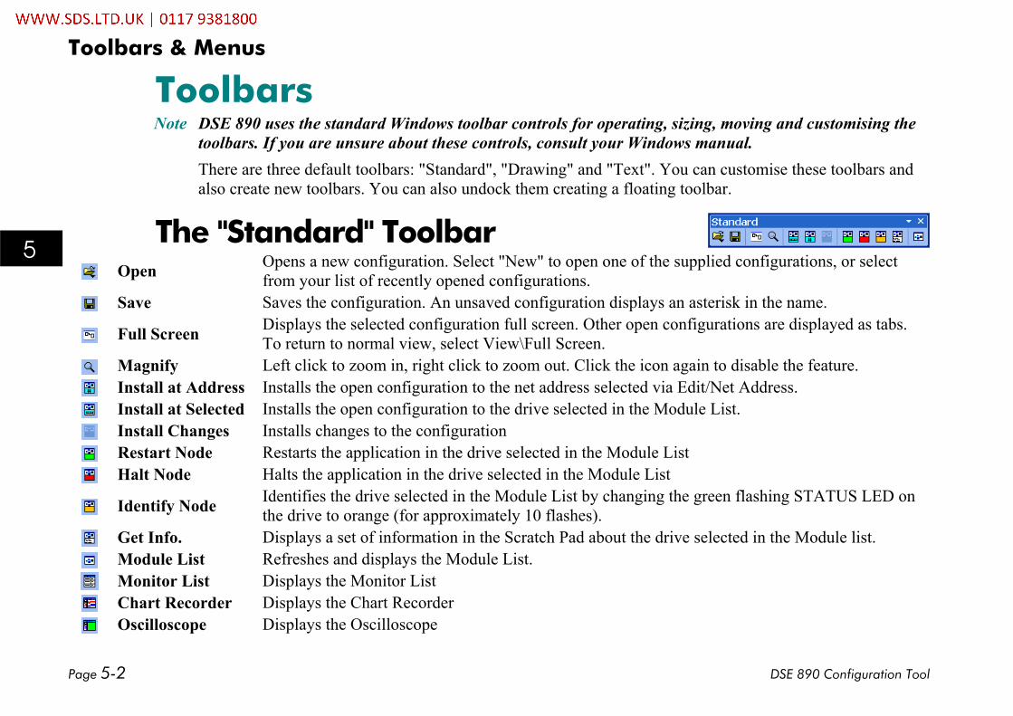
ToolbarsNote DSE 890 uses the standard Windows toolbar controls for operating, sizing, moving and customising the
toolbars. If you are unsure about these controls, consult your Windows manual.There are three default toolbars: "Standard", "Drawing" and "Text". You can customise these toolbars andalso create new toolbars. You can also undock them creating a floating toolbar.
The "Standard" ToolbarOpen Opens a new configuration. Select "New" to open one of the supplied configurations, or select
from your list of recently opened configurations.Save Saves the configuration. An unsaved configuration displays an asterisk in the name.
Full Screen Displays the selected configuration full screen. Other open configurations are displayed as tabs.To return to normal view, select View\Full Screen.
Magnify Left click to zoom in, right click to zoom out. Click the icon again to disable the feature.Install at Address Installs the open configuration to the net address selected via Edit/Net Address.Install at Selected Installs the open configuration to the drive selected in the Module List.Install Changes Installs changes to the configurationRestart Node Restarts the application in the drive selected in the Module ListHalt Node Halts the application in the drive selected in the Module List
Identify Node Identifies the drive selected in the Module List by changing the green flashing STATUS LED onthe drive to orange (for approximately 10 flashes).
Get Info. Displays a set of information in the Scratch Pad about the drive selected in the Module list.Module List Refreshes and displays the Module List.Monitor List Displays the Monitor ListChart Recorder Displays the Chart RecorderOscilloscope Displays the Oscilloscope

Toolbars & Menus
DSE 890 Configuration Tool Page 5-3
8
1
2
3
4
5
6
E
9
10
11
A
B
C
D
7
Drawing InformationDSE 890 allows to add drawing information to a configuration.This can be done by two tool bars, the Drawing and the Text toolbar.The operation of these toolbars is very intuitive and similar tomany widely used programs. For this reason, the details of the"Drawing" and "Text" toolbars are not explained.The "Drawing" and "Text" toolbars can be used to annotate theConfiguration Window and the Motor Control pane. For example,the blue diagrams in the default "New Configurations" areproduced in this way.
The "Drawing" ToolbarARROW, LINE, OVAL, RECTANGLE, IMAGE, LINE COLOR,FILL COLOR, FRONT, BACK, GROUP, UNGROUP, PATTERN,LINE WIDTH, LINE PATTERN.
The "Text" ToolbarTEXT, FONT, SIZE, FONT COLOR, BOLD, ITALIC,UNDERLINE, LEFT, CENTERED.

Toolbars & Menus
Page 5-4 DSE 890 Configuration Tool
8
9
10
11
A
B
C
D
1
2
3
4
5
6
7
E
MenusFileNew… Ctrl+N Creates a new default configuration in the selected projectOpen ► Opens a configuration from the selected projectOpen History… Opens revision history of current configurationOpen Selected F2 Opens configuration of selected module in Module ListOpen Online F9 Opens configuration of selected module in Module List in ONLINE modeExtract Selected Extracts selected items and save to a fileClose Closes the active windowClose All Closes all configurationsDiscard Removes the configuration without savingSave Ctrl+S Saves the configurationSave As… Saves the configuration to the same project using a new configuration nameSave All Saves all configurations in the selected projectImport Imports configuration elements from a fileUpdate Selected Updates configuration with parameter values from selected modulePrint Setup… Setup your printing requirementsPrint Preview Shows how the page will printPrint… Ctrl+P Prints the active windowExit Closes this program

Toolbars & Menus
DSE 890 Configuration Tool Page 5-5
8
1
2
3
4
5
6
E
9
10
11
A
B
C
D
7
EditUndo Ctrl+Z Reverses your last actionCut Ctrl+X Cuts the selected item from the window (to the clipboard)Copy Ctrl+C Copies the selected item to the clipboardPaste Ctrl+V Inserts the contents of the clipboard to the active windowDelete Deletes the selected itemImport Import selectionExport Export selectionSelect All Selects all items in the active windowDuplicate Ctrl+D Duplicates the selected item(s)Paste Time Pastes today's date and time in the Scratch PadInsert Sheet Insert a sheet into the configurationDelete Sheet Delete a sheet from the configurationDelete Form ► Delete a Form from list
Edit Form ► Edit a Form from list
Find Input… F10 Find block input by nameFind Output… F11 Find block output by nameNet Address (1)… Sets the net address for the drive module in a drive systemPerformance ►
Standard Displays standard blocks in the Block Menu (black)Advanced Displays advanced blocks in the Block Menu (green)High Displays high blocks in the Block Menu (green)
Motor Wizard Launches the Motor selection wizard
Toolbars & Menus
Page 5-6 DSE 890 Configuration Tool
8
9
10
11
A
B
C
D
1
2
3
4
5
6
7
E
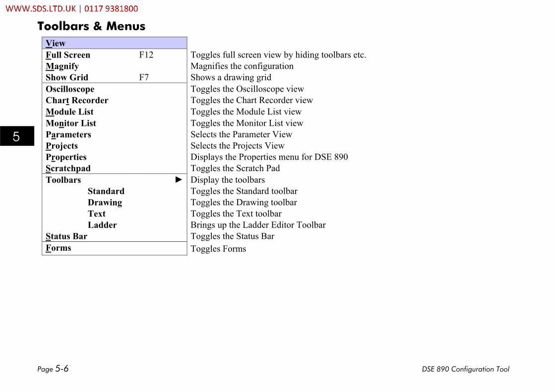
ViewFull Screen F12 Toggles full screen view by hiding toolbars etc.Magnify Magnifies the configurationShow Grid F7 Shows a drawing gridOscilloscope Toggles the Oscilloscope viewChart Recorder Toggles the Chart Recorder viewModule List Toggles the Module List viewMonitor List Toggles the Monitor List viewParameters Selects the Parameter ViewProjects Selects the Projects ViewProperties Displays the Properties menu for DSE 890Scratchpad Toggles the Scratch PadToolbars ► Display the toolbars
Standard Toggles the Standard toolbarDrawing Toggles the Drawing toolbarText Toggles the Text toolbarLadder Brings up the Ladder Editor Toolbar
Status Bar Toggles the Status BarForms Toggles Forms

Toolbars & Menus
DSE 890 Configuration Tool Page 5-7
8
1
2
3
4
5
6
E
9
10
11
A
B
C
D
7
ProjectRecent ► Select from your Recent Projects in the Projects ViewManage… Displays the Manage dialog which allows you to organise Projects and CategoriesCompact Removes old revisions and temporary files from the active CategoryUpdate… Executes "Update Configuration" for the whole project
Print… Executes "Print Configuration" for the whole project
Delete Configs… Displays a dialog which allows you to delete selected configuration
Duplicate Duplicate the project
BlockInput Network input on top level diagram, else macro inputOutput Network output on top level diagram, else macro outputMacro Block representing a block sub-diagram890 ► 890 blocks: : :Winders ► Winder blocks
Note The "Block" menu is only visible when a Configuration pane is on the screen.

Toolbars & Menus
Page 5-8 DSE 890 Configuration Tool
8
9
10
11
A
B
C
D
1
2
3
4
5
6
7
E
CommandInstall at Address Ctrl+T Installs the open configuration to the net address selected via Edit/Net Address.Install at Selected Ctrl+G Installs the open configuration to the drive selected in the Module List.Install Changes F3 Installs changes to the configurationFull Install at Selected Installs full configuration in selected driveGo Online Go ONLINE with the currently opened configurationRestart Restarts the application in the drive selected in the Module List ?Halt Halts the application in the drive selected in the Module ListIdentify Identifies the drive selected in the Module List by changing the green flashing
STATUS LED on the drive to orange (for approximately 10 flashes).Get Info. Displays a set of information in the Scratch Pad about the drive selected in the
Module listRefresh Refreshes and displays the Module List.Upgrade Firmware Upgrade drive firmwareSet Serial Number Set serial number in drive firmwareSet Performance Level Set performance level for drive

Toolbars & Menus
DSE 890 Configuration Tool Page 5-9
8
1
2
3
4
5
6
E
9
10
11
A
B
C
D
7
InsertText F4 Inserts a text boxArrow F5 Inserts a line with arrowLine F6 Inserts a lineOval Inserts an ovalRectangle F8 Inserts a rectangleImage Inserts a selected bitmap image fileForm Create… ► Create a new Form in a new view
Form X List of Forms to be inserted

Toolbars & Menus
Page 5-10 DSE 890 Configuration Tool
8
9
10
11
A
B
C
D
1
2
3
4
5
6
7
E
FormatAlign Ctrl+A Align drawing elementsText Font… Changes the font attributes of selected textText Face Select the typeface for selected textText Size Select the type size for selected textText Color Select the color for selected textBold Toggles the Bold attribute for selected textItalic Toggles the Italic attribute for selected textUnderline Toggles the Underline attribute for selected text
Left Justified Aligns selected text to the left, ragged rightCenter Text Centers selected textLine Color Select the line colorFill Color Select the fill colorMove to Front Move selected object in front of other objectsMove to Back Move selected object behind other objectsGroup Group selected objects togetherUngroup Ungroup selected compoundPattern Select a pattern fillLine Width Select a line widthLine Pattern Select a line pattern

Toolbars & Menus
DSE 890 Configuration Tool Page 5-11
8
1
2
3
4
5
6
E
9
10
11
A
B
C
D
7
WindowCascade Arranges windows as separate tabsTile Arranges split-screen windowsArrange Icons Arrange icons at the bottom of the window
HelpContents… Opens the DSE 890 manual to search the ContentsIndex… Opens the DSE 890 manual to search the IndexSearch… Opens the DSE 890 manual to search for specific wordsAbout DSE 890… Displays the version number and other information about DSE 890General -Data Sheets Opens data sheets about DSE 890

Toolbars & Menus
Page 5-12 DSE 890 Configuration Tool
8
9
10
11
A
B
C
D
1
2
3
4
5
6
7
E