dsc lab 3: accelerometer usage and vibration...
TRANSCRIPT
DSC Lab 3: Accelerometer Usage and Vibration Measurement Page 1
Introduction
Sensors that detect acceleration are called accelerometers, and this laboratory study introduceshow to set up an accelerometer for basic vibration measurement. Accelerometers are used to detectthe motion of an object or point in inertial space. Note that this is different from a displacement-type sensor that senses the relative motion between two points. Interestingly, a displacement-typesensing element is required inside most accelerometers to provide a measure of displacement orforce, which can then be used to infer acceleration. Accelerometers take advantage of instrumentedspring-mass “seismic” structures that are designed to take advantage of Newton’s law.
Acceleration is intrinsically a dynamic variable, resulting from the application of a net force on abody. Even though the acceleration, velocity, and displacement of a body are related, it is practicalto measure acceleration directly because differentiating signals from velocity or displacement sensorscan introduce large errors and noise. Generally, it can be expected that low-frequency applications(on the order of 1 Hz) are best treated by displacement sensors, while intermediate frequencies (upto 1 kHz) favor velocity sensors. High-frequency measurements usually call for use of accelerometers.Nevertheless, accelerometers are finding wide application at all frequency ranges for testing andevaluating, for safety control systems, as well as within many consumer products.
All accelerometers require some means for inferring acceleration. The sensing mechanism in oneof the devices used in this lab in the past was based on piezoresistive strain gauges. This ac-celerometer provides relatively good low frequency response and, although the calibration has arelatively low bandwidth up to 50 Hz, this is a good sensor for low frequency applications. Anotheraccelerometer that has been used in this lab provides three axes of acceleration measurement andgives measurement down to 0 Hz (DC). This accelerometer uses a force balance approach realizedusing a silicon-machined capacitive-type sensing mechanism.
A good deal of effort in vibration measurement with accelerometers requires good signal condition-ing and data analysis. The acceleration signal will generally be a dynamic signal proportional tothe induced acceleration of the case. For example, the sensitivity for an accelerometer might beabout 10 mV/g. In some applications, involving low acceleration, there may be a need to amplifythe signal. In addition, there can be a slight DC offset in the output that may be due to someimbalance (e.g., if a bridge type sensor is used). This offset can change slightly over time. Somesignal conditioning issues can be resolved by using an amplifier based on a differential amplifierdesign. This amplifier also includes an offset adjustment for removing the DC bias introduced bythe imbalance in the sensor bridge. Another type of signal conditioning that can be needed is elec-trical filtering. Filtering can become especially important if the signal-to-noise levels get too low.Finally, many accelerometers available today require only a DC voltage excitation, and embeddedelectronics provide an output DC signal proportional to the acceleration in the direction of thesensitive axis.
Absolute acceleration measurements play a vital role in many feedback control systems and pro-cesses. In inertial guidance systems, accelerometers sense the general motion of spacecraft, air-planes, and missiles. In active dampers, they supply stabilizing feedback signals. In environmentaland simulation tests, they help control the level and spectral content of motion. In testing andperfecting the structural behavior and performance of products, accelerometers measure the shock,
R.G. Longoria, Summer 2012 ME w144L, UT-Austin
DSC Lab 3: Accelerometer Usage and Vibration Measurement Page 2
vibratory, and general motion experienced. Accelerometers also provide valuable information formonitoring the health, testing the behavior, and checking the quality of machines and structures.
This lab description provide additional information on the principle of operation of basic seismicdevices, followed by two experimental studies that can be completed using equipment available inthe laboratory.
Principle of Operation: Seismic Devices / Accelerometers
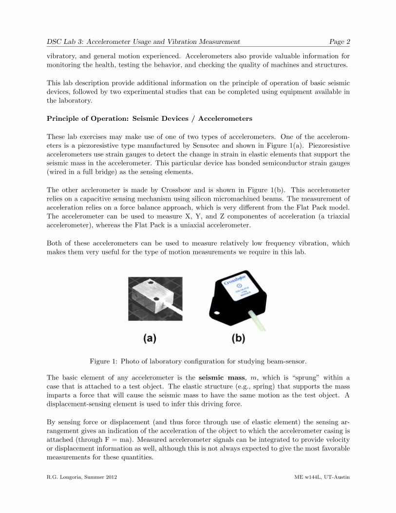
These lab exercises may make use of one of two types of accelerometers. One of the accelerom-eters is a piezoresistive type manufactured by Sensotec and shown in Figure 1(a). Piezoresistiveaccelerometers use strain gauges to detect the change in strain in elastic elements that support theseismic mass in the accelerometer. This particular device has bonded semiconductor strain gauges(wired in a full bridge) as the sensing elements.
The other acclerometer is made by Crossbow and is shown in Figure 1(b). This accelerometerrelies on a capacitive sensing mechanism using silicon micromachined beams. The measurement ofacceleration relies on a force balance approach, which is very different from the Flat Pack model.The accelerometer can be used to measure X, Y, and Z componentes of acceleration (a triaxialaccelerometer), whereas the Flat Pack is a uniaxial accelerometer.
Both of these accelerometers can be used to measure relatively low frequency vibration, whichmakes them very useful for the type of motion measurements we require in this lab.
Figure 1: Photo of laboratory configuration for studying beam-sensor.
The basic element of any accelerometer is the seismic mass, m, which is “sprung” within acase that is attached to a test object. The elastic structure (e.g., spring) that supports the massimparts a force that will cause the seismic mass to have the same motion as the test object. Adisplacement-sensing element is used to infer this driving force.
By sensing force or displacement (and thus force through use of elastic element) the sensing ar-rangement gives an indication of the acceleration of the object to which the accelerometer casing isattached (through F = ma). Measured accelerometer signals can be integrated to provide velocityor displacement information as well, although this is not always expected to give the most favorablemeasurements for these quantities.
R.G. Longoria, Summer 2012 ME w144L, UT-Austin

DSC Lab 3: Accelerometer Usage and Vibration Measurement Page 3
Figure 2: Schematic diagram of a typical seismic device.
The basic structure and operation of a translational accelerometer can be modeled as a spring-mass-damper seismic structure as shown in Figure 2. The displacement of the seismic mass in responseto an input case acceleration is modeled as a second-order system. Assume that the input motionis harmonic (e.g., a sinusoid), u(t) = uo sin(ωt), where uo is the amplitude and ω is the frequency(in rad/sec). The model of the accelerometer can be found either from a direct application ofNewton’s law or from the bond graph shown. Note that the variable of interest here, x, is therelative displacment. The base acceleration, u(t) is the input in the equation,
x+ 2ζωnx+ ω2nx = u(t),
where x is the relative position, u(t), is the sinusoidal base motion, ζ = b/2√km is the damping
coefficient, and ωn =√k/m is the natural frequency.
Figure 3: Accelerometer model as a base-excited mass-spring-damper system.
A transfer function is found by letting s replace the derivative operator, d()/dt, and then,
X
U=
1(sωn
)2+(
2ζ sωn
)+ 1
.
Note that here X and U are the “s-domain” forms of x(t) and u(t), respectively.
If we assume that a sensing element can ideally convert the relative motion to voltage, or vo = Sx ·x,
R.G. Longoria, Summer 2012 ME w144L, UT-Austin
DSC Lab 3: Accelerometer Usage and Vibration Measurement Page 4
then a transfer function between the output voltage signal and base acceleration is,
Vo
U=
[VoX
]·[X
U
]= [Sx] ·
[X
U
],
or,Vo
U=
Sx(sωn
)2+(
2ζ sωn
)+ 1
where Sx is a sensitivity constant in volts/(units displacement).
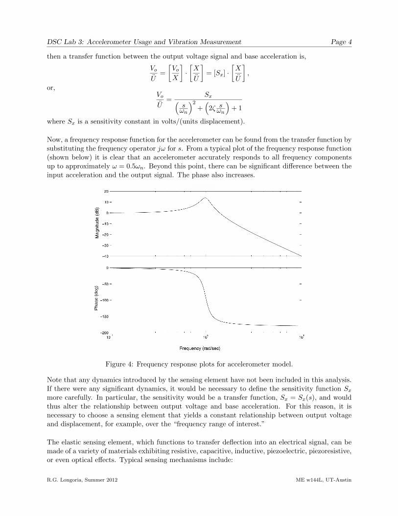
Now, a frequency response function for the accelerometer can be found from the transfer function bysubstituting the frequency operator jω for s. From a typical plot of the frequency response function(shown below) it is clear that an accelerometer accurately responds to all frequency componentsup to approximately ω = 0.5ωn. Beyond this point, there can be significant difference between theinput acceleration and the output signal. The phase also increases.
Figure 4: Frequency response plots for accelerometer model.
Note that any dynamics introduced by the sensing element have not been included in this analysis.If there were any significant dynamics, it would be necessary to define the sensitivity function Sxmore carefully. In particular, the sensitivity would be a transfer function, Sx = Sx(s), and wouldthus alter the relationship between output voltage and base acceleration. For this reason, it isnecessary to choose a sensing element that yields a constant relationship between output voltageand displacement, for example, over the “frequency range of interest.”
The elastic sensing element, which functions to transfer deflection into an electrical signal, can bemade of a variety of materials exhibiting resistive, capacitive, inductive, piezoelectric, piezoresistive,or even optical effects. Typical sensing mechanisms include:
R.G. Longoria, Summer 2012 ME w144L, UT-Austin

DSC Lab 3: Accelerometer Usage and Vibration Measurement Page 5
Capacitive Accelerometers. In a capacitive acclerometer, a capacitor is formed by a “stationary”plate (the housing which moves with the base accleration) and a moving place attached to the seis-mic mass. The distance between these plates determines the capacitance which can be monitoredto infer acceleration.Piezoresistive Accelerometers. Piezoresistive accelerometers use strain gauges to monitor strain inelastic elements that support the seismic mass.Piezoelectric Accelerometers. In piezoelectric accelerometers, a crystal sensing element is used andthis material can perform a dual function, acting as a precision spring as well as a sensing element.The crystal can be quartz or ceramic piezoelectric material (e.g., barium titanate, lead zirconitetitanate (PZT), or lead metaniobite). The piezoelectric is sandwiched between the case and theseismic mass. The sensing material is usually designed to respond either to a compressive or shear-ing type force from the seismic mass, thus making the device sensitive to acceleration.Servo Accelerometers. Servo accelerometers use an internal, closed-loop feedback control systemthat behaves like a mechanical spring. Measurement of acceleration occurs by virtue of a signalthat generates a restoring force required to keep the seismic mass at its original position.
Experiment 1: Hanging Mass-Spring Test
Goals: to learn about accelerometers and how to use them for simple vibration measurements; tocontinue learning how to used computer-based data acquisition
Background reading/resources:2 Slides on Acceleration Measurement and Applications2 Discussion on accelerometers, accelerometer model and sensor mechanisms2 Note on logarithmic decrement (ME 344 note)2 Log decrement LabVIEW program (to be provided by TA)
Pre-Laboratory Preparation:
1. Review the concept of logarithmic decrement in the handout provided on the course log, andbe prepared to use this concept in lab. Submit an explanation of how you use this method todetermine damping ratio.2. Review specifications (posted on the course log) for the type of accelerometer that will beused in this lab. Explain the following accelerometer specifications: range (g), sensitivity (mV/g),bandwidth (Hz).
Laboratory Work:NOTE: This is a quick (express) type experiment, and it takes patience to set up and to conductthe experiment. The motion of the mass in directions transverse to the vertical need to minimized.
General procedure (assume guidance by TA):1. Hang a known mass from a given spring and let it deflect under its own weight. Use a (length)scale or tape measure to make a quick check on the stiffness by noting the deflection from thespring’s free length after the mass is attached. The stiffness is roughly the weight divided by theinitial deflection (for small deflection).
R.G. Longoria, Summer 2012 ME w144L, UT-Austin
DSC Lab 3: Accelerometer Usage and Vibration Measurement Page 6
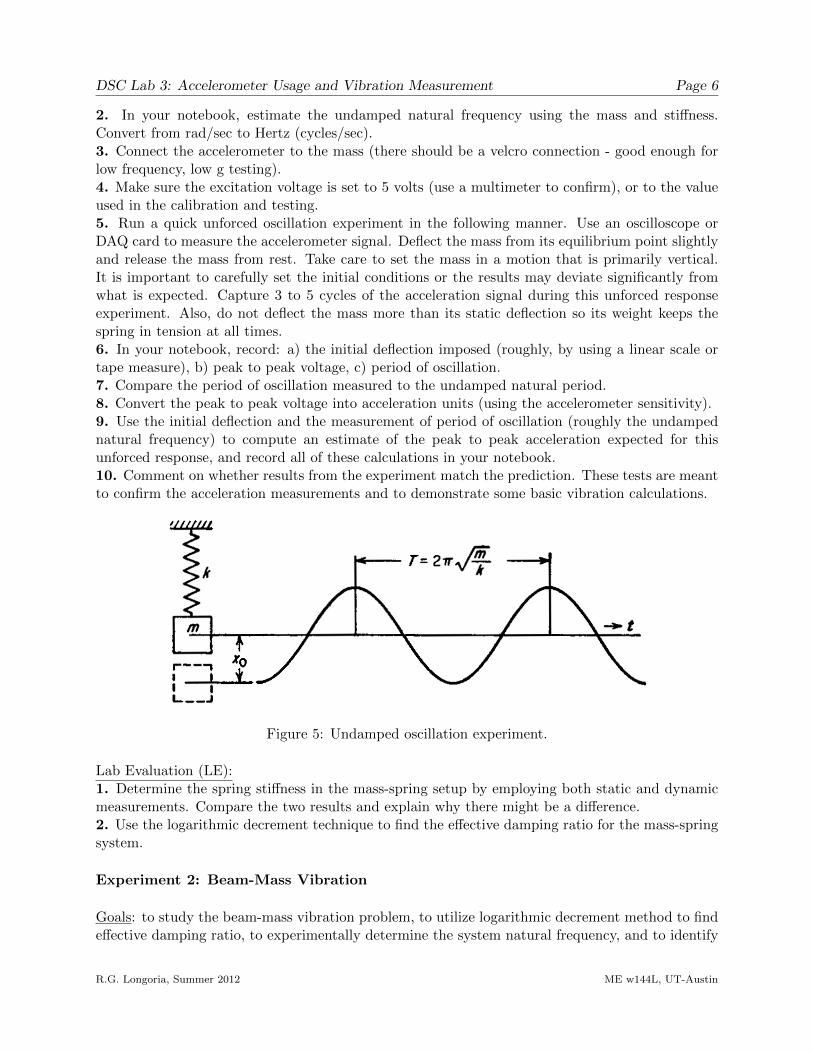
2. In your notebook, estimate the undamped natural frequency using the mass and stiffness.Convert from rad/sec to Hertz (cycles/sec).3. Connect the accelerometer to the mass (there should be a velcro connection - good enough forlow frequency, low g testing).4. Make sure the excitation voltage is set to 5 volts (use a multimeter to confirm), or to the valueused in the calibration and testing.5. Run a quick unforced oscillation experiment in the following manner. Use an oscilloscope orDAQ card to measure the accelerometer signal. Deflect the mass from its equilibrium point slightlyand release the mass from rest. Take care to set the mass in a motion that is primarily vertical.It is important to carefully set the initial conditions or the results may deviate significantly fromwhat is expected. Capture 3 to 5 cycles of the acceleration signal during this unforced responseexperiment. Also, do not deflect the mass more than its static deflection so its weight keeps thespring in tension at all times.6. In your notebook, record: a) the initial deflection imposed (roughly, by using a linear scale ortape measure), b) peak to peak voltage, c) period of oscillation.7. Compare the period of oscillation measured to the undamped natural period.8. Convert the peak to peak voltage into acceleration units (using the accelerometer sensitivity).9. Use the initial deflection and the measurement of period of oscillation (roughly the undampednatural frequency) to compute an estimate of the peak to peak acceleration expected for thisunforced response, and record all of these calculations in your notebook.10. Comment on whether results from the experiment match the prediction. These tests are meantto confirm the acceleration measurements and to demonstrate some basic vibration calculations.
Figure 5: Undamped oscillation experiment.
Lab Evaluation (LE):1. Determine the spring stiffness in the mass-spring setup by employing both static and dynamicmeasurements. Compare the two results and explain why there might be a difference.2. Use the logarithmic decrement technique to find the effective damping ratio for the mass-springsystem.
Experiment 2: Beam-Mass Vibration
Goals: to study the beam-mass vibration problem, to utilize logarithmic decrement method to findeffective damping ratio, to experimentally determine the system natural frequency, and to identify
R.G. Longoria, Summer 2012 ME w144L, UT-Austin
DSC Lab 3: Accelerometer Usage and Vibration Measurement Page 7
the effective mass, to reinforce understanding of 2nd order (mechanical) dynamics and vibration ofa beam with mass loading the tip
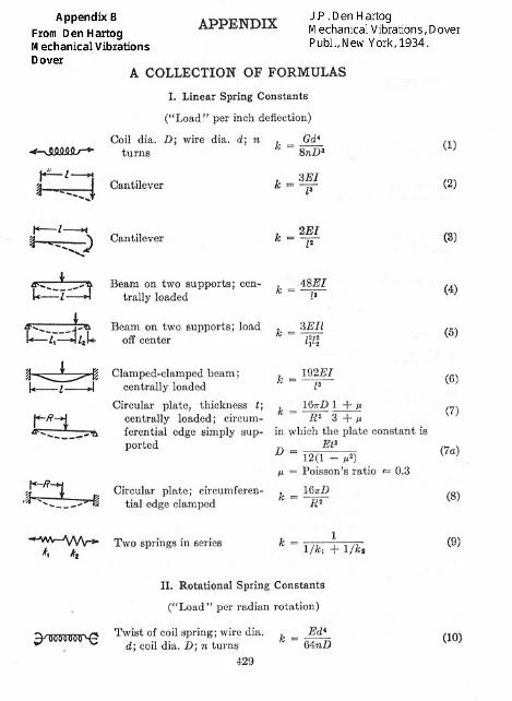
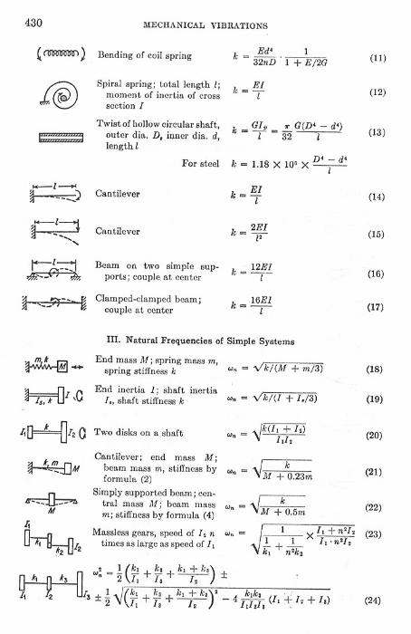
Background reading:2 The concept of ’effective mass’ can be understood by studying Rayleigh’s method, which showshow much mass of a spring, for example, should be included in the total mass of mass-spring systemso you accurately predict natural frequency. See Appendix A: “Estimating the mass-beam naturalfrequency using Rayleigh’s method”.2 Be familiar with formulas in the Den Hartog table (Appendix B).
Pre-Laboratory Preparation:1. Which formulas in the Den Hartog table(s) would you use for this lab? (Summarize yourselection and reasoning).2. Review and summarize in words how Rayleigh’s method is used in estimating the mass-beamnatural frequency.3. Outline lab procedures in your notebook for completing the proposed lab studies listed below.The TA will review your procedures and provide feedback, but you will be expected to completethe labs using your own procedure.
Proposed Lab Studies:1. With an accelerometer mounted on the end of a strain-gauged beam (such as used in previouslab), an effective mass-spring system has been created. Experimentally determine the systemdamping ratio, the damped natural frequency, the undamped natural frequency, and the total(effective) mass.2. Use your estimate of the total (effective) mass to identify the fraction of the beam’s mass that iseffectively added to the tip mass. Compare this quantity with that recommended in Den Hartog’stable (see item 21 in Den Hartog formulas).
Lab Evaluation (LE):1. Describe the procedure you developed to measure the dynamic response and to estimate thekey system parameters in the system you studied.2. Compute values for system damping ratio, the damped and undamped natural frequencies, andfor the total (effective) mass and the fractional beam mass.
R.G. Longoria, Summer 2012 ME w144L, UT-Austin