ds1780 cpu peripheral monitor - analog, linear, & mixed ... · system interrupt availability on...
TRANSCRIPT
1 of 28 032305
FEATURES Direct-to-digital temperature sensor requires
no external components or user calibration Two fan speed sensors Monitors 6 power supply voltages 8-bit DAC for fan speed control Intrusion detect for security (detects when
chassis lid has been removed, even if power is off)
Remote system reset System interrupt availability on all monitored
functions (temperature, voltages, fan speed, chassis intrusion)
2-wire interface with 2-bit addressability Integrated NAND TREE for board level
testability Wide power supply range (2.8V VDD
5.75V) High integration in a small 24-pin 173-mil
TSSOP Applications include monitoring of personal
computers or any microprocessor-based system
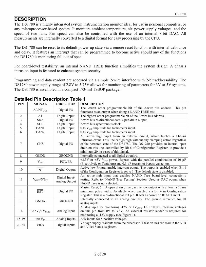
PIN ASSIGNMENT PIN DESCRIPTION A0/NTOUT - Address Input / NAND TREE Output A1 - Address Input SDA - 2-Wire Serial Data Input/Output SCL - 2-Wire Serial Clock FANx - Tachometer Inputs CHS - Chassis Intrusion Detector Input GNDD - Digital Ground VDD - Power Supply Voltage (2.8V to 5.75V) INT - Hardware Interrupt output VOUT/NTIN - DAC output / NAND TREE Input RST - Remote System Reset GNDA - Analog Ground +xxVIN - Positive Voltage Inputs +2.5VS/+VCCP2 - Positive/negative Voltage Input VIDx - Processor Voltage Supply Readout Inputs
See Table 11 on page 27 for Ordering Information
DS1780CPU Peripheral Monitor
www.dalsemi.com
DS1780E+ 24-Pin TSSOP (173-mil)
23VID0 VIDVID2 VID3 VID4 +VCCP1 +2.5 VIN +3.3 VIN +5 VIN +12 VIN +2.5 VS/+VCCP2
GNDA
123456789101112
24
22212019181716151413
SDA
FAN1
CHSGNDD
VDD
INTVOUT/NTIN
RST
A1
SCL
FAN2
A0/NTOUT
DS1780
2 of 28
DESCRIPTION The DS1780 is a highly integrated system instrumentation monitor ideal for use in personal computers, or any microprocessor-based system. It monitors ambient temperature, six power supply voltages, and the speed of two fans. Fan speed can also be controlled with the use of an internal 8-bit DAC. All measurements are internally converted to a digital format for easy processing by the CPU. The DS1780 can be reset to its default power-up state via a remote reset function with internal debounce and delay. It features an interrupt that can be programmed to become active should any of the functions the DS1780 is monitoring fall out of spec. For board-level testability, an internal NAND TREE function simplifies the system design. A chassis intrusion input is featured to enhance system security. Programming and data readout are accessed via a simple 2-wire interface with 2-bit addressability. The DS1780 power supply range of 2.8V to 5.75V allows for monitoring of parameters for 3V or 5V systems. The DS1780 is assembled in a compact 173-mil TSSOP package. Detailed Pin Description Table 1
PIN SIGNAL DIRECTION DESCRIPTION
1 A0/NTOUT Digital I/O The lowest order programmable bit of the 2-wire bus address. This pin functions as an output when doing a NAND TREE test.
2 A1 Digital Input The highest order programmable bit of the 2-wire bus address. 3 SDA Digital I/O 2-wire bus bi-directional data. Open-drain output. 4 SCL Digital Input 2-wire bus synchronous clock. 5 FAN1 Digital Input 0 to VDD amplitude fan tachometer input. 6 FAN2 Digital Input 0 to VDD amplitude fan tachometer input.
7 CHS Digital I/O
An active high input from an external circuit, which latches a Chassis Intrusion event. This line can go high without any clamping action regardless of the powered state of the DS1780. The DS1780 provides an internal open drain on this line, controlled by Bit 6 of Configuration Register, to provide a minimum 20 ms reset of this signal.
8 GNDD GROUND Internally connected to all digital circuitry.
9 VDD POWER +3.3V or +5V VDD power. Bypass with the parallel combination of 10 µF (Electrolytic or Tantalum) and 0.1 µF (ceramic) bypass capacitors.
10 INT Digital Output Active-low Programmable interrupt output. The output is enabled when Bit 1 of the Configuration Register is set to 1. The default state is disabled.
11 VOUT/NTIN Digital Input/ Analog Output
An active-high input that enables NAND Tree board-level connectivity testing. Refer to “NAND Tree Testing” Section. Used as DAC output when NAND Tree is not selected.
12 RST Digital I/O Master Reset, 5 mA open drain driver, active low output with at least a 20 ms minimum pulse width. Available when enabled via Bit 4 in Configuration Register. This is a bi-directional I/O pin. It acts as power on RESET input.
13 GNDA GROUND Internally connected to all analog circuitry. The ground reference for all analog inputs.
14 +2.5VS/+VCCP2 Analog Input Analog input for monitoring -12V or +VCCP2. DS1780 will measure voltages on this pin from 0V to 3.6V. An external resistor ladder is required for monitoring a -12V supply (see Figure 1).
15-19 +xxVIN Analog Inputs A/D inputs for 5 positive voltages.
20-24 VIDx Digital Inputs Voltage supply readouts from the processor. These values are read in the VID and VID4 Status Registers.

DS1780
3 of 28
OVERVIEW A block diagram of the DS1780 is shown in Figure 1. The DS1780 provides six analog inputs, an analog output, five digital inputs, two fan speed inputs, a temperature sensor, and interrupt registers on a single chip, which communicates on a 2-wire serial bus. The DS1780 performs power supply, temperature, and fan monitoring for personal computers. The analog voltages are divided internally by the DS1780. The inputs are then converted to 8-bit digital words. The analog inputs are intended to be connected to the several power supplies present in a typical computer. Temperature can be converted to a 9-bit two’s-complement digital word with a 0.5°C LSb. The analog output is approximately a 0-1.25V output from an 8-bit D/A converter, which is used to control fan speeds. Fan inputs measure the period of tachometer pulses from the fans, providing a higher count for lower fan speeds. The fan inputs are digital inputs with an acceptable range of 0 to VDD volts and a transition level of approximately 1.4 volts. Full-scale fan counts are 255 (8-bit counter) and this represents a stopped or very slow fan. Nominal speeds, based on a count of 153, are programmable from 1100 to 8800 RPM on FAN1 and FAN2. Signal conditioning circuitry is included to accommodate slow rise and fall times. The DS1780 provides a number of internal registers, as detailed in Table 1. These include: Configuration Register: Provides control and configuration, as well as initialization. Interrupt ( INT ) Status Registers: Two registers to provide status of each interrupt limit or interrupt event. Interrupt ( INT ) Mask Registers: Allows masking of individual Interrupt sources, as well as separate masking for the hardware interrupt output. Temperature Configuration Register: The lower 2 bits of this register configure the type of temperature interrupt mode to be used. Bit 7 reflects the lowest bit of the temperature reading. VID Register, VID4 Register: Bits 0-3 of the VID register reflect the status of the VID0-VID3 pins, bit 0 of the VID4 register reflect the status of VID4 pin. These are simply input pins - not processed in any way. In a multiprocessor system, these signals will be multiplexed externally from the various processor sources, with the source being controlled by software. Value RAM: The monitoring results and limits for temperature, voltages, and fan counts are all contained in the Value RAM. When the DS1780 is started, it cycles through each measurement in sequence, and it continuously loops through the sequence approximately once every second. Each measured value is compared to values stored in limit registers. When the measured value violates the programmed limit the DS1780 will set a corresponding System Management Interrupt (SMI) in the Interrupt Status Registers. One hardware interrupt line, INT , is available to generate an SMI. INT is fully programmable with masking of each Interrupt source, and masking of the output. In addition, the configuration register has control bits to enable or disable the hardware Interrupts.

DS1780
4 of 28
A CHS (Chassis Intrusion) digital input is provided. The Chassis Intrusion input is designed to accept an active high signal from an external circuit that latches when the case is removed from the computer; this pin is a dual purpose pin which will be driven low by the DS1780 to reset the external circuit. DS1780 FUNCTIONAL BLOCK DIAGRAM Figure 1
Note: R1 and R2 on the -12V resistance ladder should be ratioed such that approximately +2.5V appears at the input pin (i.e., R1=4kΩ, R2=23.2 kΩ). If a second processor voltage needs to be monitored (VCCP2), leave R2 empty, and make R1 500Ω, with VCCP2 appearing here. 2-WIRE SERIAL DATA BUS When using the 2-wire bus, a write will always consist of the DS1780 2-wire slave address, followed by the Internal Address Register byte, then the data byte. The Internal Address Register addresses are listed below in Table 2. There are two cases for a read: 1. If the Internal Address Register is known to be at the desired Address, simply read the DS1780 with
the 2-wire slave address, followed by the data byte read from the DS1780. 2. If the Internal Address Register value is unknown, write to the DS1780 with the 2-wire slave address,
followed by the Internal Address Register byte. Then restart the Serial Communication with a Read consisting of the 2-wire slave address, followed by the data byte read from the DS1780.
The default power-on 2-wire slave address for the DS1780 is 01011(A1)(A0) binary, where A0-A1 reflects the state of the pins defined by the same names. The address can be changed by writing any desired value to the 2-wire Serial Address Register (excluding the 2 LSBs). This communication protocol is depicted in the 2-wire timing diagrams of Figures 2 and 8.

DS1780
5 of 28
INTERNAL ADDRESS REGISTER MAP Table 2 REGISTER DS1780 INTERNAL
HEX ADDRESS POWER ON VALUE NOTES
Configuration Register 40h 0000 1000 Interrupt (INT) Status
Register 1 41h 0000 0000
Interrupt (INT) Status Register 2 42h 0000 0000
Interrupt (INT) Mask Register 1 43h 0000 0000
Interrupt (INT) Mask Register 2 44h 0000 0000
Chassis Intrusion Clear Register 46h 0000 0000
Bit 7 of this register clears Chassis Intrusion.
The other bits are reserved.
VID Register 47h 0101 XXXX The lower 4 bits reflect
the state of VID0-VID3 pins.
Serial Address Register 48h 0010 11XY X Reflects state of A1 and Y Reflects A0 state
VID4 Register 49h 1000 000X Bit 0 = VID 4. The rest are reserved.
Temperature Configuration
Register 4Bh 0000 0001
Test Register 15h 0000 0000 Do not alter the contents of the register.
Analog output 19h 1111 1111 Full on Value RAM 20h-3Dh Company ID 3Eh 1101 1010 Read only
Stepping 3Fh 0000 0001 Read only

DS1780
6 of 28
2-WIRE SERIAL COMMUNICATION WITH THE DS1780 Figure 2
OPERATION - Power-on Applying power to the DS1780 causes a reset of several of the registers. Power-on conditions of the registers are shown in Table 2 above. Some registers have indeterminate power-on values, such as the Limit and RAM registers of the Value RAM page, and these are not shown in the table. Upon power-up the ADC is inactive. Writing Limits into the Value RAM should usually be the first action performed after power up. The RST pin is bi-directional. It forces RESET at power-on, but can also be pulled low to force RESET internally. OPERATION - Resets The DS1780 features four distinct resetting functions. Each one has a different effect on register contents and the state of the RST output following the event. Each one is explained below: Power-on Reset - On POR, all internal logic is reset, and registers are cleared to their default state (see tables 10.x). Because Value RAM is typically the first area programmed upon power-up, it does not have a defined state upon POR. Also, on POR, the RST output will be pulled to an active low state for 20 ms (minimum). A POR occurs every time VDD crosses the voltage level approximately equivalent to the sum of one n-channel threshold (VTN) and one p-channel threshold (VTP), on a power-up or power-down condition. DS1780 SRAM contents get “scrambled” when VDD falls below the greater of one n-channel VT or one p-channel VT. Therefore, SRAM contents will always be in a defined state as supply voltage reaches the minimum spec level of 2.8V, even in a power supply brownout condition.

DS1780
7 of 28
Software Reset - This condition is generated by writing a 1 to bit 4 of the configuration register. It has no effect on DS1780 register contents. It will however pull the RST output to the active low state for a duration of 20 ms (minimum). When the RST output goes active, this bit in the configuration register will clear itself. A Software Reset is only possible if Bit 7 of the INT Mask Register 2 (0x44h) is set to “1”. Device Initialization - This condition is generated by writing a 1 to bit 7 of the configuration register. It will clear all registers in DS1780 memory to their default state except the Value RAM (0x20h - 0x3Dh) and analog output (0x19h). These locations will remain unchanged from their state before the initialization. This condition has no effect on the RST output. This bit is self-clearing. Hardware Reset - This condition is generated by some external source pulling the RST pin below VIN(0) (see DC Electrical Characteristics). The DS1780 will then force the RST signal to remain in the active low state for >20 ms. It will clear all registers in DS1780 memory to their default state except the Value RAM (0x20h - 0x3Dh) and analog output (0x19h). These locations will remain unchanged from their state before the Hardware Reset. OPERATION - Configuration Register Control of the DS1780 is provided through the configuration register. The Configuration Register is used to start and stop the DS1780, enable or disable interrupt output and modes, and provide the initialization function described above. Bit 0 of the Configuration Register controls the monitoring loop of the DS1780. Setting Bit 0 low stops the monitoring loop and puts the DS1780 into a standby mode. 2-Wire Bus communication is still possible with any register in the DS1780 during the standby mode, however. Additionally, the DS1780 will continue to monitor the RST and CHS inputs while in a standby mode. Setting Bit 0 high starts the monitoring loop. Bit 1 of the Configuration Register enables or disables the INT Interrupt output. Setting Bit 1 high enables the INT output, setting bit 1 low disables the output. Bit 3 of the Configuration Register is used to clear the INT interrupt output when set high. The DS1780 monitoring function will stop until bit 3 is set low. Interrupt Status register contents will not be affected. Bit 4 of the Configuration Register is used to initiate a minimum 20 ms RESET signal on the RST output if the pin is configured for the RESET mode (via bit 7 of the INT Mask Register 2 - 0x44h). Bit 6 of the Configuration Register is used to reset the Chassis Intrusion (CHS) output pin when set high. Bit 7 of the Configuration Register is used to start a Configuration Register Initialization when taken high, as described in the “OPERATION - Resets” section. OPERATION - Monitoring Loop The DS1780 monitoring function is started by doing a write to the Configuration Register and setting the INT_Clear (Bit 3) low, and Start (Bit 0) high. At this point the INT_Enable (Bit 1) should be set high to enable interrupts (INT). The DS1780 then performs a “round robin” sampling of the inputs, sampling each approximately once a second, in the order (corresponding to locations in the Value RAM) shown below in Table 3. The results of the sampling and conversions can be found in the Value RAM (Table 10.13) and are available at any time.
DS1780
8 of 28
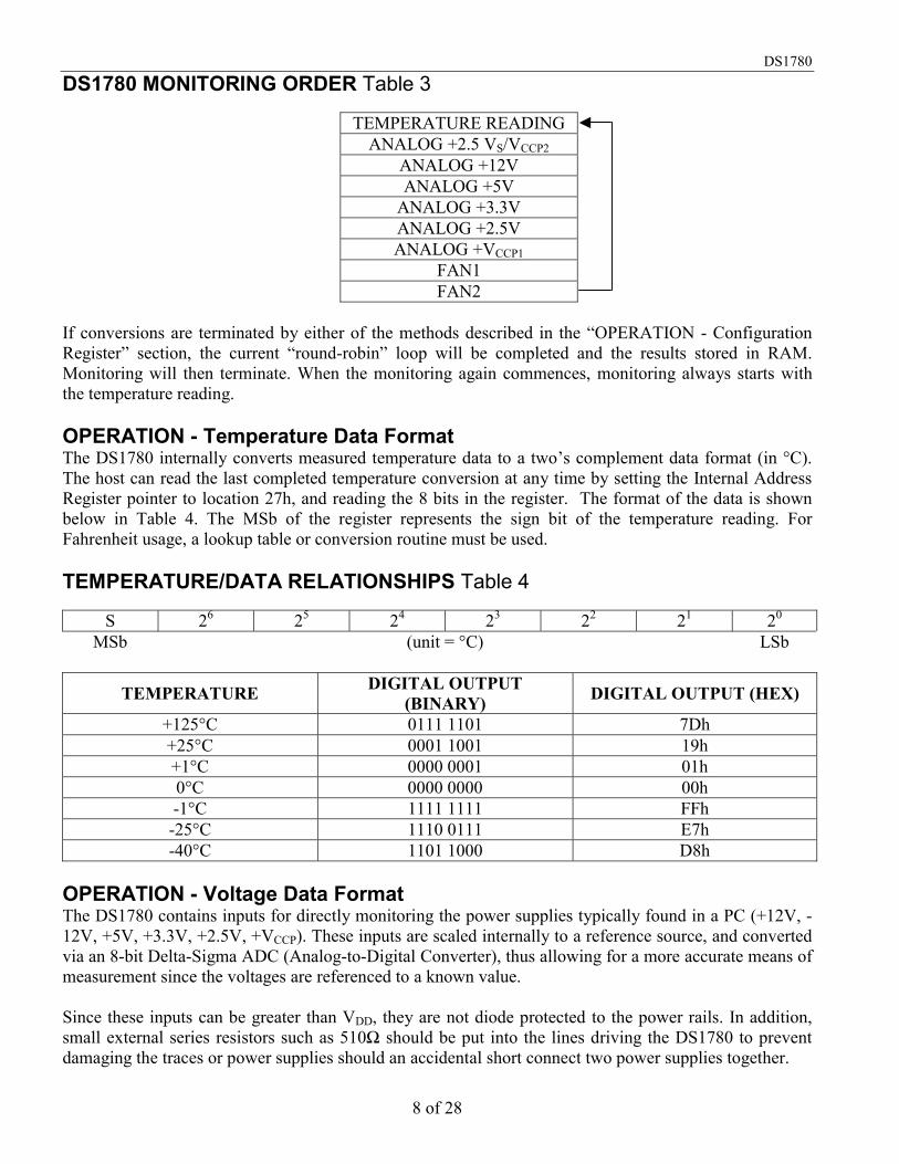
DS1780 MONITORING ORDER Table 3
TEMPERATURE READING ANALOG +2.5 VS/VCCP2
ANALOG +12V ANALOG +5V
ANALOG +3.3V ANALOG +2.5V ANALOG +VCCP1
FAN1 FAN2
If conversions are terminated by either of the methods described in the “OPERATION - Configuration Register” section, the current “round-robin” loop will be completed and the results stored in RAM. Monitoring will then terminate. When the monitoring again commences, monitoring always starts with the temperature reading. OPERATION - Temperature Data Format The DS1780 internally converts measured temperature data to a two’s complement data format (in °C). The host can read the last completed temperature conversion at any time by setting the Internal Address Register pointer to location 27h, and reading the 8 bits in the register. The format of the data is shown below in Table 4. The MSb of the register represents the sign bit of the temperature reading. For Fahrenheit usage, a lookup table or conversion routine must be used. TEMPERATURE/DATA RELATIONSHIPS Table 4
S 26 25 24 23 22 21 20 MSb (unit = °C) LSb
TEMPERATURE DIGITAL OUTPUT (BINARY) DIGITAL OUTPUT (HEX)
+125°C 0111 1101 7Dh +25°C 0001 1001 19h +1°C 0000 0001 01h 0°C 0000 0000 00h -1°C 1111 1111 FFh -25°C 1110 0111 E7h -40°C 1101 1000 D8h
OPERATION - Voltage Data Format The DS1780 contains inputs for directly monitoring the power supplies typically found in a PC (+12V, -12V, +5V, +3.3V, +2.5V, +VCCP). These inputs are scaled internally to a reference source, and converted via an 8-bit Delta-Sigma ADC (Analog-to-Digital Converter), thus allowing for a more accurate means of measurement since the voltages are referenced to a known value. Since these inputs can be greater than VDD, they are not diode protected to the power rails. In addition, small external series resistors such as 510Ω should be put into the lines driving the DS1780 to prevent damaging the traces or power supplies should an accidental short connect two power supplies together.
DS1780
9 of 28
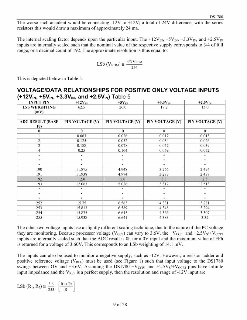
The worse such accident would be connecting -12V to +12V; a total of 24V difference, with the series resistors this would draw a maximum of approximately 24 ma. The internal scaling factor depends upon the particular input. The +12VIN, +5VIN, +3.3VIN, and +2.5VIN inputs are internally scaled such that the nominal value of the respective supply corresponds to 3/4 of full range, or a decimal count of 192. The approximate resolution is thus equal to:
LSb (VNOM) 256V 4/3 NOM
This is depicted below in Table 5. VOLTAGE/DATA RELATIONSHIPS FOR POSITIVE ONLY VOLTAGE INPUTS (+12VIN, +5VIN, +3.3VIN, and +2.5VIN) Table 5
INPUT PIN +12VIN +5VIN +3.3VIN +2.5VIN LSb WEIGHTING
(mV) 62.5 26.0 17.2 13.0
ADC RESULT (BASE
10) PIN VOLTAGE (V) PIN VOLTAGE (V) PIN VOLTAGE (V) PIN VOLTAGE (V)
0 0 0 0 0 1 0.063 0.026 0.017 0.013 2 0.125 0.052 0.034 0.026 3 0.188 0.078 0.052 0.039 4 0.25 0.104 0.069 0.052 • • •
• • •
• • •
• • •
• • •
190 11.875 4.948 3.266 2.474 191 11.938 4.974 3.283 2.487 192 12.0 5.0 3.3 2.5 193 12.063 5.026 3.317 2.513
• • •
• • •
• • •
• • •
• • •
252 15.75 6.563 4.331 3.281 253 15.813 6.589 4.348 3.294 254 15.875 6.615 4.366 3.307 255 15.938 6.641 4.383 3.32
The other two voltage inputs use a slightly different scaling technique, due to the nature of the PC voltage they are monitoring. Because processor voltage (VCCP) can vary to 3.6V, the +VCCP1 and +2.5VS/+VCCP1 inputs are internally scaled such that the ADC result is 0h for a 0V input and the maximum value of FFh is returned for a voltage of 3.60V. This corresponds to an LSb weighting of 14.1 mV. The inputs can also be used to monitor a negative supply, such as -12V. However, a resistor ladder and positive reference voltage (VREF) must be used (see Figure 1) such that input voltage to the DS1780 swings between OV and +3.6V. Assuming the DS1780 +VCCP1 and +2.5VS/+VCCP2 pins have infinite input impedance and the VREF is a perfect supply, then the resolution and range of -12V input are:
LSb (R1, R2) 2553.6
1
21
RRR

DS1780
10 of 28
VMIN (VREF, R1, R2) - 1
2
RR VREF
VMAX (VREF, R1, R2) VREF-(VREF-3.6)
1
21
RRR
If the +2.5VS/+VCCP2 is to be used to monitor a secondary processor core voltage (VCCP2), R2 should be removed and R1=500Ω. Table 6 below shows the voltage/data relationship for these inputs in the ideal case. In this example, VREF=+5.0V, R1=4.0 kΩ, and R2=23.2 kΩ. Analog inputs will provide best accuracy when referred to the GNDA pin. A separate, low-impedance ground plane for analog ground, which provides a ground point for the voltage dividers and analog components will provide best performance but is not mandatory. Analog components such as voltage dividers should be located physically as close as possible to the DS1780. The power supply bypass, the parallel combination of 10 µF (electrolytic or tantalum) and 0.1 µF (ceramic) bypass capacitors connected between pin 9 and ground, should also be located as close as possible to the DS1780. VOLTAGE/DATA RELATIONSHIPS FOR VCCP VOLTAGE INPUTS (+VCCP1, +2.5VS/ +VCCP2) Table 6
INPUT PIN +VCCP1 +2.5VS/+VCCP2 LSb WEIGHTING (mV) 14.1 96.0
(Used to monitor VCCP) (Used to monitor -12V) ADC RESULT (BASE 10) PIN VOLTAGE (V) SUPPLY VOLTAGE (V)
0 0 -29.0 1 0.014 -28.90 2 0.028 -28.81 3 0.042 -28.71 4 0.056 -28.62 • • •
• • •
• • •
136 1.920 -15.94 137 1.934 -15.85 138 1.948 -15.75 139 1.962 -15.66
• • •
• • •
• • •
252 3.558 -4.808 253 3.572 -4.712 254 3.586 -4.616 255 3.60 -4.52
OPERATION - FAN Speed Data Format Inputs are provided for signals from fans equipped with tachometer outputs. These are logic-level inputs with an approximate threshold of 1.4V. Signal conditioning in the DS1780 accommodates the slow rise and fall times typical of fan tachometer outputs. The maximum input signal range is 0 to VDD. In the event these inputs are supplied from fan outputs which exceed 0 to VDD, either resistive division or diode clamping must be included to keep inputs within an acceptable range, as shown in Figure 3. R2 is selected so that it does not develop excessive voltage due to input leakage. R1 is selected based on R2 to provide a minimum input of 2V and a maximum of VDD. R1 should be as low as possible to provide the

DS1780
11 of 28
maximum possible input up to VDD for best noise immunity. Alternatively, use a shunt reference or Zener diode to clamp the input level. Tables 7 and 8 describe the format of the data stored in the FAN reading registers (Internal Address Registers 28h and 29h). FAN TACHOMETER INPUT OPTIONS Figure 3
VOLTAGE/DATA RELATIONSHIPS FOR FAN INPUTS (FAN1, FAN2) UNDER DEFAULT (÷2) MODE Table 7
RPM Timer Per Revolution Counts for “Divide by 2” (default mode) in decimal Comments 4400 13.64 ms 153 Typical RPM 3080 19.48 ms 219 70% RPM 2640 22.73 ms 255 (maximum) 60% RPM
VOLTAGE/DATA RELATIONSHIPS FOR FAN INPUTS (FAN1, FAN 2) Table 8
MODE SELECT
NOMINAL RPM
TIME PER REVOLUTION
COUNTS FOR THE NOMINAL
SPEED IN DECIMAL 70% RPM
TIME PER REVOLUTION FOR
70% RPM Divide by 1 8800 6.82 ms 153 6160 9.74 ms Divide by 2 4400 13.64 ms 153 3080 19.48 ms Divide by 4 2200 27.27 ms 153 1540 38.96 ms Divide by 8 1100 54.54 ms 153 770 77.92 ms
In general, the value stored in the FAN registers (in decimal) follows the equation:
Count (RPM, Divisor) Divisor RPM
10 x 1.35 6
If fans can be powered while the power to the DS1780 is off, the DS1780 inputs will provide diode clamping. Limit input current to the Input Current at Any Pin specification shown in the ABSOLUTE MAXIMUM RATINGS section. In most cases, open collector outputs with pullup resistors inherently limit this current. If this maximum current could be exceeded, either a larger pullup resistor should be used or resistors connected in series with the fan inputs. The Fan Inputs gate an internal 22.5 kHz oscillator for one period of the Fan signal into an 8-bit counter (maximum count = 255). The default divisor, located in the Fan Divisor/RST_Register, is set to 2 (choices are 1, 2, 4, and 8) providing a nominal count of 153 for a 4400 rpm fan with two pulses per revolution. Typical practice is to consider 70% of normal RPM a fan failure, at which point the count will be 219.

DS1780
12 of 28
OPERATION - Interrupts An external interrupt can come from the following sources. While the label suggests a specific type or source of interrupt, this label is not a restriction on the usage; it could come from any desired source. 1. Analog Voltage: An interrupt will be generated if a analog voltage high or low limit has been
exceeded; this is generally when a power supply is out of its normal operating range. 2. Temperature: An interrupt will be generated if a high or a low hot temperature limit has been
exceeded. 3. Fan speed: An interrupt will be generated if a fan count limit has been exceeded. 4. Chassis Intrusion: This is an active high interrupt from any type of device that detects and captures
chassis intrusion violations. This could be accomplished mechanically, optically, or electrically, and circuitry external to the DS1780 is expected to latch the event.
All System Management Interrupts (SMIs) are indicated in the two Interrupt Status Registers. The INT output has individual mask registers and individual masks for each Interrupt. As described in the “OPERATION - Configuration Register” Section, this hardware Interrupt line can also be enabled/disabled in the Configuration Register. Reading an Interrupt Status Register will output the contents of the Register, and reset the Register. A subsequent read done before the analog ‘round-robin’ monitoring loop is complete will indicate a cleared Register. Allow at least 1 second to allow all Registers to be updated between reads. In summary, the Interrupt Status Register clears upon being read, and requires at least 1 second to be updated. When the Interrupt Status Register clears, the hardwire interrupt line will also clear until the Registers are updated by the monitoring loop. The INT hardware Interrupt output is cleared with the INT_Clear bit, which is Bit 3 of the Configuration Register, without affecting the contents of the Interrupt Status Registers. When this bit is high, the DS1780 monitoring loop will stop. It will resume when the bit is low. Analog Voltage Limits The limits for the analog voltage comparison are programmed into the Value RAM at Internal Address Registers 2Bh - 36h. A high and low limit is associated with each of the 6 analog voltage inputs of the DS1780. Care must be taken to program the limit registers in the same format as the respective voltage data register. Please see “OPERATION - Voltage Data Format” for details. For setting a voltage interrupt, the DS1780 compares on a “greater than” basis for high limits and a “less than or equal to” basis for low limits. The host can mask any or all of the voltage limits for interrupt contention. Temperature Limits and Interrupt Modes The host programs an 8-bit high temperature limit and hysteresis/low temperature limit into the DS1780 at Internal Address Registers 39h and 3 Ah in the same two’s complement format described in the “OPERATION - Temperature Data Format” section. The temperature mode is programmed into the Temperature Configuration Register (0x4Bh). A digital 8-bit comparator is also incorporated that compares the temperature readings to the programmed limits. There are three interrupt modes of operation. The INT output can be programmed for either of the three interrupt modes of operation and the host can program the DS1780 to completely mask temperature interrupts from controlling the INT output.
DS1780
13 of 28
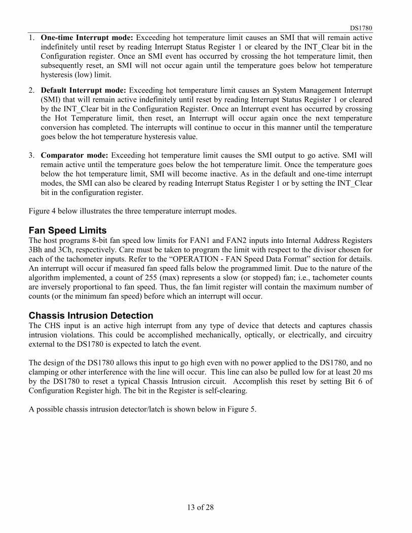
1. One-time Interrupt mode: Exceeding hot temperature limit causes an SMI that will remain active indefinitely until reset by reading Interrupt Status Register 1 or cleared by the INT_Clear bit in the Configuration register. Once an SMI event has occurred by crossing the hot temperature limit, then subsequently reset, an SMI will not occur again until the temperature goes below hot temperature hysteresis (low) limit.
2. Default Interrupt mode: Exceeding hot temperature limit causes an System Management Interrupt
(SMI) that will remain active indefinitely until reset by reading Interrupt Status Register 1 or cleared by the INT_Clear bit in the Configuration Register. Once an Interrupt event has occurred by crossing the Hot Temperature limit, then reset, an Interrupt will occur again once the next temperature conversion has completed. The interrupts will continue to occur in this manner until the temperature goes below the hot temperature hysteresis value.
3. Comparator mode: Exceeding hot temperature limit causes the SMI output to go active. SMI will
remain active until the temperature goes below the hot temperature limit. Once the temperature goes below the hot temperature limit, SMI will become inactive. As in the default and one-time interrupt modes, the SMI can also be cleared by reading Interrupt Status Register 1 or by setting the INT_Clear bit in the configuration register.
Figure 4 below illustrates the three temperature interrupt modes. Fan Speed Limits The host programs 8-bit fan speed low limits for FAN1 and FAN2 inputs into Internal Address Registers 3Bh and 3Ch, respectively. Care must be taken to program the limit with respect to the divisor chosen for each of the tachometer inputs. Refer to the “OPERATION - FAN Speed Data Format” section for details. An interrupt will occur if measured fan speed falls below the programmed limit. Due to the nature of the algorithm implemented, a count of 255 (max) represents a slow (or stopped) fan; i.e., tachometer counts are inversely proportional to fan speed. Thus, the fan limit register will contain the maximum number of counts (or the minimum fan speed) before which an interrupt will occur. Chassis Intrusion Detection The CHS input is an active high interrupt from any type of device that detects and captures chassis intrusion violations. This could be accomplished mechanically, optically, or electrically, and circuitry external to the DS1780 is expected to latch the event. The design of the DS1780 allows this input to go high even with no power applied to the DS1780, and no clamping or other interference with the line will occur. This line can also be pulled low for at least 20 ms by the DS1780 to reset a typical Chassis Intrusion circuit. Accomplish this reset by setting Bit 6 of Configuration Register high. The bit in the Register is self-clearing. A possible chassis intrusion detector/latch is shown below in Figure 5.

DS1780
14 of 28
TEMPERATURE INTERRUPT MODE ILLUSTRATION Figure 4
SAMPLE CHASSIS INTRUSION DETECTOR/LATCH Figure 5

DS1780
15 of 28
OPERATION - Analog Output The DS1780 has a single analog output from a unsigned 8-bit D/A which produces 0-1.25 volts; this is amplified and scaled with external circuitry such as a op-amp and transistor to provide fan speed control. This register is set to 0xFF on power-up, which produces full fan speed. The analog output register (19h) is unaffected by any reset other than power-on. This voltage must be scaled and have an output current of at least 250 mA which is needed to drive the fans; Figure 6 is a simple circuit that can be used, and Table 9 suggest R1 and R2 to select gain. Although it is recommended to connect the DS1780 analog output to a high impedance node such as that in Figure 6, the output driver can source 2.0 mA (max) at VOUT = 1.25V while maintaining the error spec of 5% of FSR over temperature and supply voltage. Stability is guaranteed for a load capacitance up to 100 pF. More capacitance could cause severe overshoots and possible oscillation. FAN AMPLIFIER CIRCUIT EXAMPLE Figure 6
AMPLIFIER DESIGN EXAMPLES Table 9 Input 1.22 Output 12 Gain 9.84
R1 R2 1,000 9,000 2,200 19,439 3,300 29,159 4,700 41,530 10,000 88,361
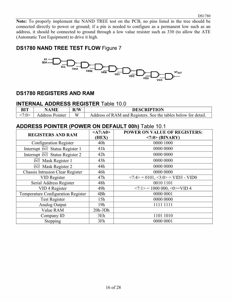
OPERATION - NAND TREE Test A NAND tree is provided in the DS1780 for Automated Test Equipment (ATE) board level connectivity testing. If the user applies (VDD - 0.5V) to the NTIN input, the device will be in the NAND tree test mode. A0/NTOUT will become the NAND tree output pin. To perform a NAND tree test all pins included in the NAND tree (see Figure 7 below) should be driven high. Beginning with A1 and working around the chip, each pin can be toggled and a resulting toggle can be observed on A0/NTOUT. Allow for a typical propagation delay of 100 ns.
DS1780
16 of 28
Note: To properly implement the NAND TREE test on the PCB, no pins listed in the tree should be connected directly to power or ground; if a pin is needed to configure as a permanent low such as an address, it should be connected to ground through a low value resister such as 330 (to allow the ATE (Automatic Test Equipment) to drive it high. DS1780 NAND TREE TEST FLOW Figure 7
DS1780 REGISTERS AND RAM INTERNAL ADDRESS REGISTER Table 10.0
BIT NAME R/W DESCRIPTION <7:0> Address Pointer W Address of RAM and Registers. See the tables below for detail.
ADDRESS POINTER (POWER ON DEFAULT 00h) Table 10.1
REGISTERS AND RAM <A7:A0> (HEX)
POWER ON VALUE OF REGISTERS: <7:0> (BINARY)
Configuration Register 40h 0000 1000 Interrupt INT Status Register 1 41h 0000 0000 Interrupt INT Status Register 2 42h 0000 0000
INT Mask Register 1 43h 0000 0000 INT Mask Register 2 44h 0000 0000
Chassis Intrusion Clear Register 46h 0000 0000 VID Register 47h <7:4> = 0101, <3:0> = VID3 - VID0
Serial Address Register 48h 0010 1101 VID 4 Register 49h <7:1> = 1000 000, <0>=VID 4
Temperature Configuration Register 4Bh 0000 0001 Test Register 15h 0000 0000
Analog Output 19h 1111 1111 Value RAM 20h-3Dh Company ID 3Eh 1101 1010
Stepping 3Fh 0000 0001
DS1780
17 of 28
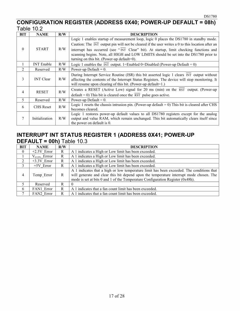
CONFIGURATION REGISTER (ADDRESS 0X40; POWER-UP DEFAULT = 08h) Table 10.2
BIT NAME R/W DESCRIPTION
0 START R/W
Logic 1 enables startup of measurement loop, logic 0 places the DS1780 in standby mode. Caution: The INT output pin will not be cleared if the user writes a 0 to this location after an interrupt has occurred (see “ INT Clear” bit). At startup, limit checking functions and scanning begins. Note, all HIGH and LOW LIMITS should be set into the DS1780 prior to turning on this bit. (Power-up default=0).
1 INT Enable R/W Logic 1 enables the INT output. 1=Enabled 0=Disabled (Power-up Default = 0) 2 Reserved R/W Power-up Default = 0.
3 INT Clear R/W During Interrupt Service Routine (ISR) this bit asserted logic 1 clears INT output without affecting the contents of the Interrupt Status Registers. The device will stop monitoring. It will resume upon clearing of this bit. (Power-up default=1.)
4 RESET R/W Creates a RESET (Active Low) signal for 20 ms (min) on the RST output. (Power-up default = 0) This bit is cleared once the RST pulse goes active.
5 Reserved R/W Power-up Default = 0.
6 CHS Reset R/W Logic 1 resets the chassis intrusion pin. (Power-up default = 0) This bit is cleared after CHS becomes cleared.
7 Initialization R/W Logic 1 restores power-up default values to all DS1780 registers except for the analog output and value RAM, which remain unchanged. This bit automatically clears itself since the power on default is 0.
INTERRUPT INT STATUS REGISTER 1 (ADDRESS 0X41; POWER-UP
DEFAULT = 00h) Table 10.3 BIT NAME R/W DESCRIPTION
0 +2.5V_Error R A 1 indicates a High or Low limit has been exceeded. 1 VCCP1_Errror R A 1 indicates a High or Low limit has been exceeded. 2 +3.3V_Error R A 1 indicates a High or Low limit has been exceeded. 3 +5V_Error R A 1 indicates a High or Low limit has been exceeded.
4 Temp_Error R A 1 indicates that a high or low temperature limit has been exceeded. The conditions that will generate and clear this bit depend upon the temperature interrupt mode chosen. The mode is set at bits 0 and 1 of the Temperature Configuration Register (0x48h).
5 Reserved R 0 6 FAN1_Error R A 1 indicates that a fan count limit has been exceeded. 7 FAN2_Error R A 1 indicates that a fan count limit has been exceeded.

DS1780
18 of 28
INTERRUPT INT STATUS REGISTER 2 (ADDRESS 0X42; POWER-UP
DEFAULT=00h) Table 10.4 BIT NAME R/W DESCRIPTION
0 +12V_Error R A 1 indicates a High or Low limit has been exceeded.
1 -12V/ VCCP2_Error R A 1 indicates a High or Low limit has been exceeded.
2 Reserved R 0 3 Reserved R 0 4 Chassis_Error R A 1 indicates Chassis Intrusion has gone high. 5 Reserved R 0 6 Reserved R 0 7 Reserved R 0
Note: Anytime the INT Status Registers are read out, the conditions (i.e., Registers) that are read are automatically reset to power-up state (except CHS, which can only be cleared by CHS reset). In the case of the VOLTAGE priority indication, if two or more voltages were out of LIMITS, then another indication would automatically be generated if it were not handled during the ISR. The errant voltage may be masked until the operator has time to clear the errant condition or set the limit higher/lower. INT MASK REGISTER 1 (ADDRESS 0X43; POWER-UP DEFAULT=00h) Table 10.5
BIT NAME R/W DESCRIPTION 0 +2.5V R/W A 1 disables the corresponding interrupt status bit for INT interrupt. 1 +VCCP1 R/W A 1 disables the corresponding interrupt status bit for INT interrupt. 2 +3.3V R/W A 1 disables the corresponding interrupt status bit for INT interrupt. 3 +5V R/W A 1 disables the corresponding interrupt status bit for INT interrupt. 4 Temp R/W A 1 disables the corresponding interrupt status bit for INT interrupt. 5 Reserved R/W Power on default = 0. 6 FAN1 R/W A 1 disables the corresponding interrupt status bit for INT interrupt. 7 FAN2 R/W A 1 disables the corresponding interrupt status bit for INT interrupt.
INT MASK REGISTER 2 (ADDRESS 0X44; POWER-UP DEFAULT=00h) Table 10.6
BIT NAME R/W DESCRIPTION 0 +12V R/W A 1 disables the corresponding interrupt status bit for INT interrupt. 1 -12V/VCCP2 R/W A 1 disables the corresponding interrupt status bit for INT interrupt. 2 Reserved R/W Power-up Default = 0. 3 Reserved R/W Power-up Default = 0.
4 CHS_sec (Chassis
Intrusion) R/W A 1 disables the corresponding interrupt status bit for INT interrupt.
5 Reserved R/W Power-up Default = 0. 6 Reserved R/W Power-up Default = 0. 7 Reset Enable R/W A 1 enables the RESET in the configuration register.

DS1780
19 of 28
RESERVED REGISTER (ADDRESS 0X45; POWER-UP DEFAULT=00h) Table 10.7
BIT NAME R/W DESCRIPTION <7:0> RESERVED R/W Undefined (Power On = 00h).
CHASSIS INTRUSION CLEAR REGISTER (ADDRESS 0X46; POWER-UP
DEFAULT=00h) Table 10.8 BIT NAME R/W DESCRIPTION 0-6 RESERVED R/W Undefined (Power On = 00h).
7 Chassis Int Clear R/W A 1 outputs a minimum 20 ms active low pulse on the Chassis Intrusion (CHS) pin. The
register bit clears itself after the pulse has been output. VID REGISTER (ADDRESS 0x47; POWER-UP DEFAULT = SEE “ADDRESS POINTER” TABLE) Table 10.9
BIT NAME R/W DESCRIPTION
0-3 VID R The VID[3:0] inputs from Pentium/PRO power supplies to indicate the operating voltage (e.g., 1.5V to 2.9V).
4-5 FAN1 RPM control R/W
FAN1 Speed Control. <5:4> = 00 - divide by 1 <5:4> = 01 - divide by 2 <5:4> = 10 - divide by 4 <5:4> = 11 - divide by 8
6-7 FAN2 RPM control R/W
FAN2 Speed Control. <7:6> = 00 - divide by 1 <7:6> = 01 - divide by 2 <7:6> = 10 - divide by 4 <7:6> = 11 - divide by 8
SERIAL ADDRESS REGISTER (ADDRESS 0x48; POWER-UP DEFAULT = SEE DESCRIPTION BELOW) Table 10.10
BIT NAME R/W DESCRIPTION
0-7 2-Wire Bus Address R/W 2-Wire Bus Address (Power On = 001011(A1)(A0)).
VID4 REGISTER (ADDRESS 0x49; POWER-UP DEFAULT = SEE DESCRIPTION BELOW Table 10.11
BIT NAME R/W DESCRIPTION 0 VID 4 R VID4 Input.
1-7 Reserved R/W Default Power On Values = 1000000.
DS1780
20 of 28
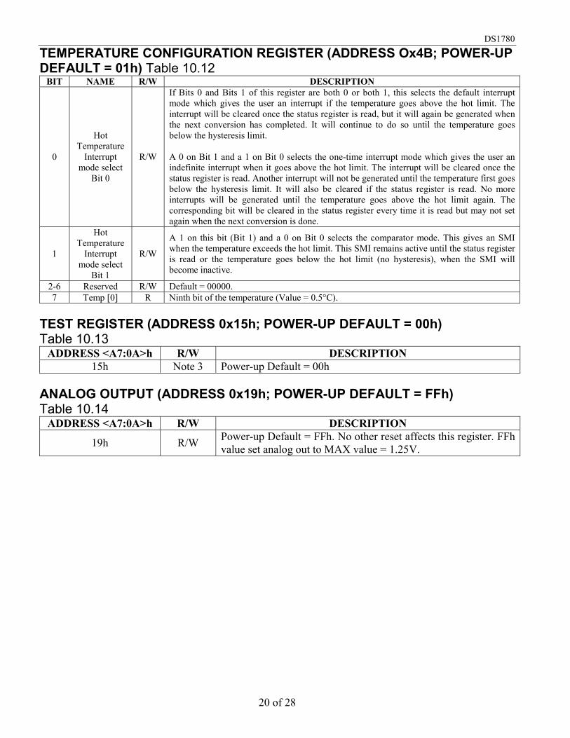
TEMPERATURE CONFIGURATION REGISTER (ADDRESS Ox4B; POWER-UP
DEFAULT = 01h) Table 10.12 BIT NAME R/W DESCRIPTION
0
Hot Temperature
Interrupt mode select
Bit 0
R/W
If Bits 0 and Bits 1 of this register are both 0 or both 1, this selects the default interrupt mode which gives the user an interrupt if the temperature goes above the hot limit. The interrupt will be cleared once the status register is read, but it will again be generated when the next conversion has completed. It will continue to do so until the temperature goes below the hysteresis limit. A 0 on Bit 1 and a 1 on Bit 0 selects the one-time interrupt mode which gives the user an indefinite interrupt when it goes above the hot limit. The interrupt will be cleared once the status register is read. Another interrupt will not be generated until the temperature first goes below the hysteresis limit. It will also be cleared if the status register is read. No more interrupts will be generated until the temperature goes above the hot limit again. The corresponding bit will be cleared in the status register every time it is read but may not set again when the next conversion is done.
1
Hot Temperature
Interrupt mode select
Bit 1
R/W
A 1 on this bit (Bit 1) and a 0 on Bit 0 selects the comparator mode. This gives an SMI when the temperature exceeds the hot limit. This SMI remains active until the status register is read or the temperature goes below the hot limit (no hysteresis), when the SMI will become inactive.
2-6 Reserved R/W Default = 00000. 7 Temp [0] R Ninth bit of the temperature (Value = 0.5°C).
TEST REGISTER (ADDRESS 0x15h; POWER-UP DEFAULT = 00h) Table 10.13
ADDRESS <A7:0A>h R/W DESCRIPTION 15h Note 3 Power-up Default = 00h
ANALOG OUTPUT (ADDRESS 0x19h; POWER-UP DEFAULT = FFh) Table 10.14
ADDRESS <A7:0A>h R/W DESCRIPTION
19h R/W Power-up Default = FFh. No other reset affects this register. FFh value set analog out to MAX value = 1.25V.

DS1780
21 of 28
VALUE RAM (ADDRESS 0x15h - 0x3Dh) Table 10.15 ADDRESS <A7:A0>h R/W DESCRIPTION
20h R +2.5V Input Reading. 21h R VCCP1 Input Reading. 22h R +3.3V Input Reading. 23h R +5V Input Reading. 24h R +12V Input Reading. 25h R +2.5V_Sense/VCCP2 Input Reading. 26h R Reserved. 27h R Temperature reading (Most significant 8-bits).
28h R FAN1 reading: This location stores the number of counts of the internal clock per revolution.
29h R FAN2 reading: This location stores the number of counts of the internal clock per revolution.
2Ah R/W Reserved. 2Bh R/W +2.5V High Limit (Note 1, 2). 2Ch R/W +2.5V Low Limit (Note 2). 2Dh R/W +VCCP1 High Limit (Note 1, 2). 2Eh R/W +V CCP1 Low Limit (Note 2). 2Fh R/W +3.3V High Limit (Note 1, 2). 30h R/W +3.3V Low Limit (Note 2). 31h R/W +5V High Limit (Note 1, 2). 32h R/W +5V Low Limit (Note 2). 33h R/W +12V High Limit (Note 1, 2). 34h R/W +12V Low Limit (Note 2). 35h R/W +2.5V_Sense/Vccp2 High Limit (Note 1, 2). 36h R/W +2.5V_Sense/Vccp2 Low Limit (Note 2). 37h Reserved. 38h Reserved. 39h R/W Hot Temperature (High) Limit (Note 1). 3Ah R/W Hot Temperature Hysteresis (Low) Limit. 3Bh R/W FAN1 Fan Count Limit: It is the number of counts of the internal clock for the
Low Limit of the fan speed.
3Ch R/W FAN2 Fan Count Limit: It is the number of counts of the internal clock for the Low Limit of the fan speed.
3Dh Reserved. 3Eh R Company id number (Note 5). 3Fh R Stepping id number (Note 6).
NOTES: 1. Setting all 1s to the high limits for voltages and fans (0111 1111 binary for temperature) means
interrupts will never be generated except the case when voltages go below the low limits. 2. For the high limits of the voltages, the device is doing a greater than comparison. For the low limits,
however, it is doing a less than or equal comparison. 3. This register should only be used by the manufacturer for testing of the ASIC. Reading or writing to
this register during normal use may lead to erroneous events.

DS1780
22 of 28
4. This register will latch an 8-bit value into an R-2R D/A to provide a range of 0-1.25 volts; accuracy can be ±5% or more.
5. This location will contain the company identification number which will be used by software to
determine analog voltage curves; this register is read only. 6. This location will contain the stepping number of the part; this register is read only. ABSOLUTE MAXIMUM RATINGS* Voltage on VDD (GNDD-0.3V) to +6.5V Voltage on any other pin (except Analog Inputs) (GNDD-0.3V) to (VDD + 0.3V) Voltage at +12VIN pin (GNDD-0.3V) to 18V Voltage at other Analog input pins (GNDD-0.3V) to 7.0V Ground Difference (GNDD-GNDA) ±0.3V Input Current at any Pin (Note 2) ±5 mA Package Input Current (Note 2) ±20 mA Operating Temperature -40°C to +125°C Storage Temperature -65°C to +150°C ESD Susceptibility (Human Body Model) 2kV Soldering Temperature (Note 3) 215°C for 60 seconds (Vapor Phase) 220°C for 15 seconds (IR)
* This is a stress rating only and functional operation of the device at these or any other conditions above those indicated in the operation sections of this specification is not implied. Exposure to absolute maximum rating conditions for extended periods of time may affect reliability. The Dallas Semiconductor DS1780 is built to the highest quality standards and manufactured for long term reliability. All Dallas Semiconductor devices are made using the same quality materials and manufacturing methods. However, the DS1780 is not exposed to environmental stresses, such as burn-in, that some industrial applications require. For specific reliability information on this product, please contact the factory in Dallas at (972) 371-4448. RECOMMENDED DC OPERATING CONDITIONS (-40°C to +125°C, 2.8V VDD 5.75V)
PARAMETER SYMBOL CONDITION MIN TYP MAX UNITS NOTES Supply Voltage VDD 2.8 5.75 V
Ground Difference ∆GND IGNDD-GNDAI 0.1 V
Digital Input Voltage VIND -0.05 VDD+0.05 V
DS1780
23 of 28
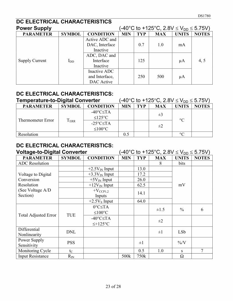
DC ELECTRICAL CHARACTERISTICS Power Supply (-40°C to +125°C, 2.8V VDD 5.75V)
PARAMETER SYMBOL CONDITION MIN TYP MAX UNITS NOTES Active ADC and DAC, Interface
Inactive 0.7 1.0 mA
ADC, DAC and Interface Inactive
125 µA Supply Current IDD
Inactive ADC and Interface, DAC Active
250 500 µA
4, 5
DC ELECTRICAL CHARACTERISTICS: Temperature-to-Digital Converter (-40C to +125C, 2.8V VDD 5.75V)
PARAMETER SYMBOL CONDITION MIN TYP MAX UNITS NOTES -40°CTA 125°C ±3
Thermometer Error TERR -25°CTA 100°C ±2
°C
Resolution 0.5 °C DC ELECTRICAL CHARACTERISTICS: Voltage-to-Digital Converter (-40°C to +125°C, 2.8V VDD 5.75V)
PARAMETER SYMBOL CONDITION MIN TYP MAX UNITS NOTES ADC Resolution 8 bits
+2.5VIN Input 13.0 +3.3VIN Input 17.2 +5VIN Input 26.0 +12VIN Input 62.5
+VCCP1,2 Inputs 14.1
Voltage to Digital Conversion Resolution (See Voltage A/D Section)
+2.5VS Input 64.0
mV
0°CTA 100°C
±1.5 % 6 Total Adjusted Error TUE
-40°CTA +125°C ±2
Differential Nonlinearity DNL ±1 LSb
Power Supply Sensitivity PSS ±1 %/V
Monitoring Cycle tC 0.5 1.0 s 7 Input Resistance RIN 500k 750k Ω

DS1780
24 of 28
DC ELECTRICAL CHARACTERISTICS: Fan RPM-to-Digital Converter (-40°C to +125°C, 2.8V VDD 5.75V)
PARAMETER SYMBOL CONDITION MIN TYP MAX UNITS NOTES
0°CTA 100°C ±6
Accuracy -40°CTA
+125°C ±12 %
Full scale count 255 decimal
Divisor=1; Fan Count=153 8800
Divisor=2; Fan Count=153 4400
Divisor=4; Fan Count=153 2200
FAN1 & FAN2 Normal Input RPM
Divisor=8; Fan Count=153 1100
RPM 8
Internal Oscillator Frequency +25°CTA
+75°C 21.15 22.5 23.85 kHz
DC ELECTRICAL CHARACTERISTICS: Analog Output VOUT (-40°C to +125°C, 2.8V VDD 5.75V)
PARAMETER SYMBOL CONDITION MIN TYP MAX UNITS NOTES DAC Resolution 8 bits Voltage Range 0 1.25 V
Error DACERR ±5 % of FSR
Output Current IOUT 2.0 mA Load Capacitance CLOAD 100 pF
DC ELECTRICAL CHARACTERISTICS: Digital Outputs: A0NTOUT (-40°C to +125°C, 2.8V VDD 5.75V)
PARAMETER SYMBOL CONDITION MIN TYP MAX UNITS NOTES IOUT=±5 mA at
VDD=4.25V Logical “1” Output Voltage VOUT(1) IOUT=±3 mA at
VDD=2.85V
2.4
V
IOUT=±5 mA at VDD=5.75V Logical “0”
Output Voltage VOUT(0) IOUT=±3 mA at VDD=3.45V
0.4 V
DS1780
25 of 28
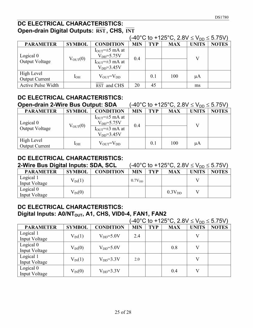
DC ELECTRICAL CHARACTERISTICS: Open-drain Digital Outputs: RST , CHS, INT (-40°C to +125°C, 2.8V VDD 5.75V)
PARAMETER SYMBOL CONDITION MIN TYP MAX UNITS NOTES IOUT=±5 mA at
VDD=5.75V Logical 0 Output Voltage VOUT(0) IOUT=±3 mA at
VDD=3.45V
0.4
V
High Level Output Current IOH VOUT=VDD 0.1 100 µA
Active Pulse Width RST and CHS 20 45 ms DC ELECTRICAL CHARACTERISTICS: Open-drain 2-Wire Bus Output: SDA (-40°C to +125°C, 2.8V VDD 5.75V)
PARAMETER SYMBOL CONDITION MIN TYP MAX UNITS NOTES IOUT=±5 mA at
VDD=5.75V Logical 0 Output Voltage VOUT(0) IOUT=±3 mA at
VDD=3.45V
0.4
V
High Level Output Current IOH VOUT=VDD 0.1 100 µA
DC ELECTRICAL CHARACTERISTICS: 2-Wire Bus Digital Inputs: SDA, SCL (-40°C to +125°C, 2.8V VDD 5.75V)
PARAMETER SYMBOL CONDITION MIN TYP MAX UNITS NOTES Logical 1 Input Voltage VIN(1) 0.7VDD V
Logical 0 Input Voltage VIN(0) 0.3VDD V
DC ELECTRICAL CHARACTERISTICS: Digital Inputs: A0/NTOUT, A1, CHS, VID0-4, FAN1, FAN2 (-40°C to +125°C, 2.8V VDD 5.75V)
PARAMETER SYMBOL CONDITION MIN TYP MAX UNITS NOTES Logical 1 Input Voltage VIN(1) VDD=5.0V 2.4 V
Logical 0 Input Voltage VIN(0) VDD=5.0V 0.8 V
Logical 1 Input Voltage VIN(1) VDD=3.3V 2.0 V
Logical 0 Input Voltage VIN(0) VDD=3.3V 0.4 V

DS1780
26 of 28
DC ELECTRICAL CHARACTERISTICS: All Digital Inputs (-40°C to +125°C, 2.8V VDD 5.75V)
PARAMETER SYMBOL CONDITION MIN TYP MAX UNITS NOTES Logical 1 Input Current IIN(1) VIN=VDD -1 -0.005 µA
Logical 0 Input Current IIN(0) VIN=0V 0.005 1 µA
Input Capacitance CIN 20 pF AC ELECTRICAL CHARACTERISTICS: 2-Wire Interface (-40°C to +125°C, 2.8V VDD 5.75V)
PARAMETER SYMBOL CONDITION MIN TYP MAX UNITS NOTES SCL Clock Period t1 2.5 µs Data In Setup Time to SCL High t2 100 ns
Data Out Stable after SCL Low t3 0 ns
SDA Low Setup Time to SCL Low (START)
t4 100 ns
SDA High Hold Time after SCL High (STOP)
t5 100 ns

DS1780
27 of 28
2-WIRE BUS TIMING DIAGRAM Figure 8
NOTES: 1. All voltages are referenced to ground, unless otherwise specified. When the input voltage (VIN) at any pin exceeds the power supplies (VIN< (GND or GNDA) or VIN
>VDD, except for analog voltage inputs), the current at that pin should be limited to 5 mA. The 20 mA maximum package input current rating limits the number of pins that can safely exceed the power supplies with an input current of 5 mA to four.
2. Solder according to IPC standards. 3. IDD specified with open-drain output pin open. 4. IDD specified with VCC at 5.0V and SDA, SCL = 5.0V. 5. TUE (Total Unadjusted Error) includes Offset, Gain and Linearity errors of the ADC. 6. Monitoring Cycle Time includes temperature conversion, voltage conversions, and fan speed
readings. 7. The total fan count is based on 2 pulses per revolution of the fan tachometer output. 8. Limits (Min and Max specs) are defined for the full temperature range -40°C TA +125°C and
voltage range 2.8V VDD 5.75V, unless otherwise stated as a condition. Typical values represent parametric norms at TA = 25°C at 4.5V VDD 5.5V, unless otherwise stated as a condition.
ORDERING INFORMATION Table 11
ORDERING NUMBER
PACKAGE MARKING DESCRIPTION
DS1780E+ DS1780 (See Note) DS1780 in Lead-Free 24-pin TSSOP
DS1780E+T&R DS1780 (See Note) DS1780 in Lead-Free 24-pin TSSOP, 1000 Piece Tape-and-Reel
DS1780E DS1780 DS1780 in 24-pin TSSOP DS1780E/T&R DS1780 DS1780 in 24-pin TSSOP, 1000 Piece Tape-and-Reel
Note: A "+" symbol will also be marked on the package near the Pin 1 indicator
DS1780
28 of 28
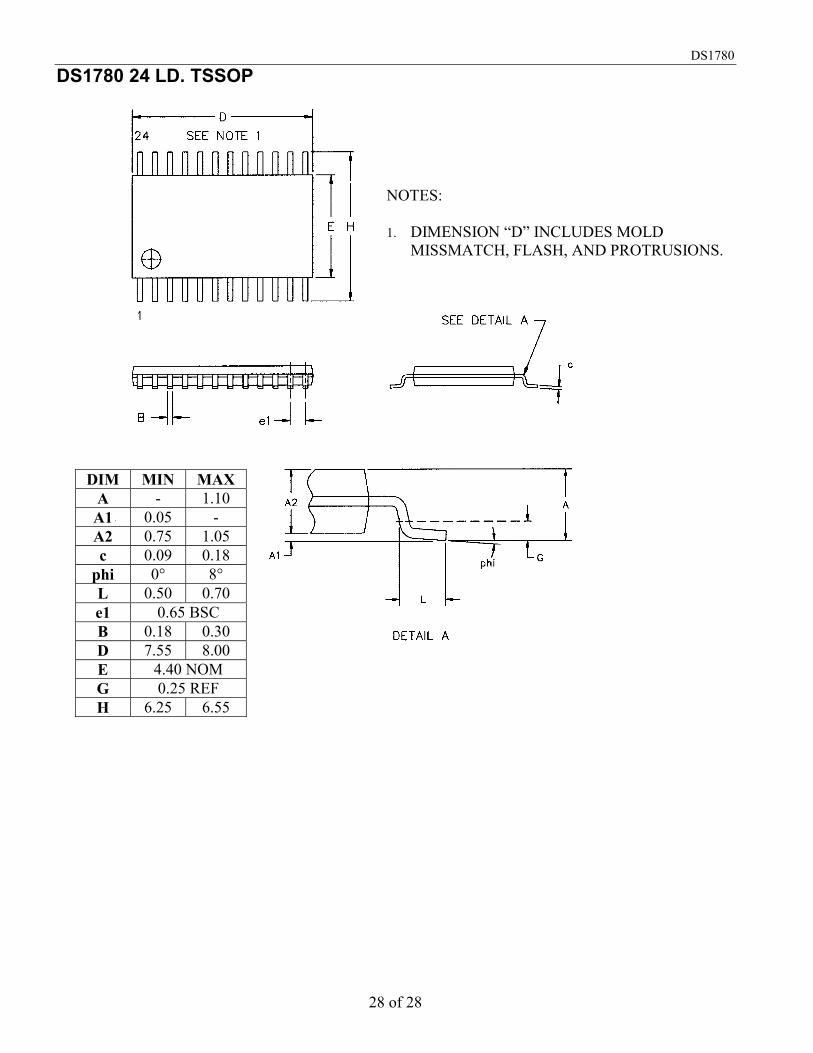
DS1780 24 LD. TSSOP
DIM MIN MAX A - 1.10 A1 0.05 - A2 0.75 1.05 c 0.09 0.18
phi 0° 8° L 0.50 0.70 e1 0.65 BSC B 0.18 0.30 D 7.55 8.00 E 4.40 NOM G 0.25 REF H 6.25 6.55
NOTES: 1. DIMENSION “D” INCLUDES MOLD
MISSMATCH, FLASH, AND PROTRUSIONS.