drop-in refrigeration system installation & operation manual
TRANSCRIPT

www.manitowocfsusa.com 800-225-9916 1
Drop-In Refrigeration System Installation & Operation
Manual
Manitowoc Foodservice Walk-In Division 2915 Tennessee Avenue North
Parsons, TN 38363 Phone: 800-225-9916
www.manitowocfsusa.com
550002878-3 May 2013

www.manitowocfsusa.com 800-225-9916 2
Table of Contents
Safety Information...…………………..………………………………………. 3 Receiving Inspection ……………………………………………………. ….. 3 Walk-In Installation………………………….………………………………… 4 Clearance Requirements………………….…………………………………. 4 Roof Curb and Membrane……………………………………………………. 5 Top Mount Installation...………………………………………………………. 6 - 7 Drain Line………………………………………………………………………. 7 Side Mount Installation.………………………………………………………. 8 - 9 Start Up and Operation………………………………………………………… 10 Thermostat……………….……………………………………………………… 11 Electric Defrost Timer ……………………………………………………….. 12 Air Defrost Timer …………………………………………………………….. 13 Maintenance ………………………………………………………………….. 14 Warranty Information ………………………………………………………… 14 Wiring Diagrams……………………………………………………………… 15 - 22

www.manitowocfsusa.com 800-225-9916 3
General Safety Information
Read this manual carefully before beginning the installation and operation of the refrigeration system. Special attention is required to all sections identified with the following warning and caution notices:
WARNING Text in a Warning box alerts you to a potential personal injury situation. Read each Warning statement before proceeding and work carefully.
CAUTION Text in a Caution box alerts you to a situation in which you could damage the refrigeration system. Read each Caution statement before proceeding and work carefully. Disregarding these special notices may result in personal injury and/or damage to the refrigeration system. Safety Notices:
Installation and maintenance/servicing are to be performed only by trained and qualified personnel familiar with commercial refrigeration systems.
Ensure that all field wiring conforms to the equipment requirements and all
applicable local and national codes.
Disconnect all power sources before servicing the refrigeration equipment.
Sheet metal and coil surfaces have sharp edges. Use appropriate protective gloves to prevent injury.
Use appropriate eye protection during installation and servicing.
Receiving Inspection
Check the shipment carefully and compare to the bill of lading. Account for all items listed and inspect each container for damage. Carefully inspect for any concealed damage. Report any shortages or damages to the carrier, note on the bill of lading, and file a freight claim. Damaged material cannot be returned to the manufacturer without prior approval. A Return Material Authorization (RMA) must be obtained. Contact a sales representative at 800-826-7036.

www.manitowocfsusa.com 800-225-9916 4
Walk-In Installation
Installation and operation instructions for the walk-in are provided separately. A copy of this manual can be obtained from the website at www.manitowocfsusa.com or by calling technical service at 800-225-9916.
Clearance Requirements
A minimum of 18” clearance is required on all sides of the unit to allow proper air
flow and serviceability of the system.
A supply of clean ambient air or ventilated air is required to maintain acceptable condensing temperatures (less than 110° ambient) and allow removal of heated discharge air from the condensing unit area.
Example of Minimum Clearance Requirements
CAUTION Failure to observe clearance and air flow requirements will result in poor system performance, premature equipment failure, and inability to service the system!
Drop-In Refrigeration Unit Building Wall
Building Wall
18” min
18” min

www.manitowocfsusa.com 800-225-9916 5
Roof Curb and Membrane – Outdoor Models Only:

www.manitowocfsusa.com 800-225-9916 6
Top Mount Models - Installation Installing Unit to Ceiling Panel: Lift the unit from its shipping crate using the lift rings located on top of the unit. Center the evaporator air intake/discharge over the panel opening and lower into position. To ensure there is no air infiltration into the walk-in, the gasket around the evaporator box must seal around the panel opening. Loosen the screws with slotted holes that connect the condensing unit to the evaporator box. Push down on the evaporator box to ensure the gasket is sealed, check to ensure the condensing unit base is level and supported, then retighten the screws. Once the unit is level and sealed, secure the unit to the ceiling panel and remove the diagonal shipping braces from the condensing and louvered ends of the unit.
WARNING Do not lift the unit by the refrigerant tubing or other components. These features will not support the unit weight. Injury and unit damage may occur!

www.manitowocfsusa.com 800-225-9916 7
Wiring and Electrical Connections:
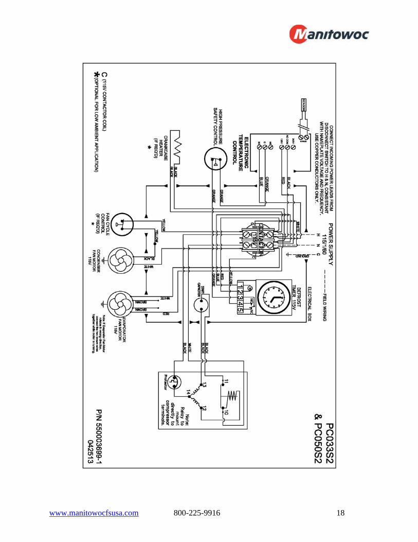
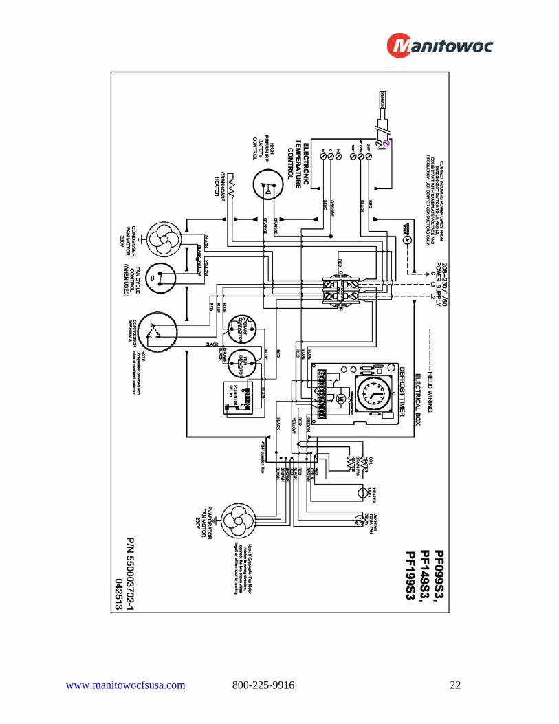
All electrical connections and routing must comply with local and national codes. Do not modify the factory installed wiring without written factory approval. Refer to the serial plate on the unit to determine the proper electrical power supply. Wire type should be of copper conductor only and properly sized to handle the electrical load. Unit wiring diagrams are attached inside the electrical box cover and in the back of this manual. The electrical box is located behind the condensing unit housing louver.
WARNING All wiring must comply with local and national codes. Wiring must be performed only by a refrigeration technician or certified electrician. Failure to follow these guidelines may result in injury!
CAUTION Check all wiring connections, including factory terminals, before operation. Connections can become loose during shipment and installation. Drain Line – Outdoor Models Only: Connect a copper drain line to the evaporator drain using a compression fitting. Do not reduce the drain line size. Slope the drain line a minimum of ½” per foot to allow proper drainage. The drain line must be wrapped with heat tape and insulated with a minimum ½” thick Armaflex. Install a P-trap in the drain line to prevent the suction of ambient temperatures into the evaporator compartment which can lead to excessive humidity and icing issues.

www.manitowocfsusa.com 800-225-9916 8
Side Mount Models - Installation
Installing Unit to Wall Panel: Position the unit as close as possible to the walk-in before removing from the shipping skid. Remove the system from the shipping skid and carefully slide the unit into the wall panel opening. Level the unit by adjusting the leveling legs. There are rivnuts around the perimeter of the opening. Using the supplied bolts, attach the unit to the walk-in by the flange around the evaporator compartment. Tighten the bolts until the gasket material is compressed to a thickness of approximately 1/8”. Apply a 3/8” bead of silicone around the perimeter of the evaporator compartment to ensure an air tight seal.
WARNING The Side Mount Unit is top heavy and can easily tip over causing injury and unit damage!

www.manitowocfsusa.com 800-225-9916 9
Wiring and Electrical Connections:
All electrical connections and routing must comply with local and national codes. Do not modify the factory installed wiring without written factory approval. Refer to the serial plate on the unit to determine the proper electrical power supply. Wire type should be of copper conductor only and properly sized to handle the electrical load. Unit wiring diagrams are attached inside the electrical box cover and in the back of this manual. The electrical box is located behind the condensing unit housing side panel.
WARNING All wiring must comply with local and national codes. Wiring must be performed only by a refrigeration technician or certified electrician. Failure to follow these guidelines may result in injury!
CAUTION Check all wiring connections, including factory terminals, before operation. Connections can become loose during shipment and installation.

www.manitowocfsusa.com 800-225-9916 10
Start-Up – All Models
The Drop-In refrigeration systems are designed for quick and easy startup. Once electrical connects are made per the wiring diagram, the following settings and checks should be performed:
Set the defrost control time and verify the defrost initiation settings. See pages 12 - 13 for additional details.
Verify/Set the temperature control to desired temperature range. Coolers are
factory preset to 35° F; Freezers are factory preset to -10° F. See page 11 for instructions on how to adjust the thermostat.
After the all system checks have been checked, properly adjusted, and verified, replace all electrical box covers, housings, etc. File a copy of this manual for future reference.
Operation – All Models
The Drop-In refrigeration systems are of the draw through design. The walk-in air is drawn into the supply air grill, through the evaporator coil, and discharged out the return air grill into the walk-in. Any interruption or obstruction of the supply or return air streams will result in unsatisfactory operation of the system.
Coolers: When powered on, the evaporator fan(s) run continuously, even during defrost cycles, and the condensing unit will cycle on/off to maintain the walk-in temperature.
Freezers: When powered on, the evaporator fan(s) run continuously except
when the system is in defrost and for a short period after the defrost cycle is complete. The condensing unit will cycle on/off to maintain walk-in temperature.
o Notice – walk-in temperatures will elevate above the set point during
defrost cycles (approximately 30 – 45 minutes, 4 times per day) but will return to the set point once the defrost cycle is complete.
CAUTION Do not block the the supply and return air grills or the air space around the air grills. Keep plastic wrappings, paper, labels, etc. from being airborne and lodging in the grills. Failure to keep the air grills clear will result in unsatisfactory operation of the system.
www.manitowocfsusa.com 800-225-9916 11
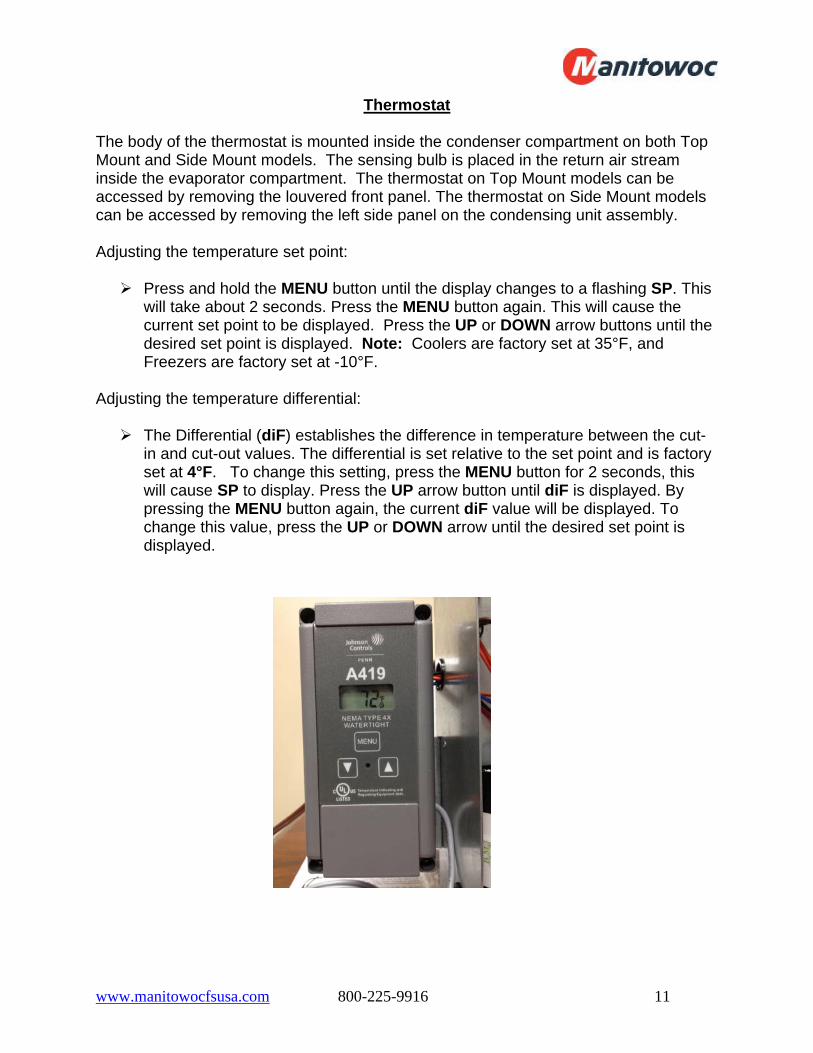
Thermostat
The body of the thermostat is mounted inside the condenser compartment on both Top Mount and Side Mount models. The sensing bulb is placed in the return air stream inside the evaporator compartment. The thermostat on Top Mount models can be accessed by removing the louvered front panel. The thermostat on Side Mount models can be accessed by removing the left side panel on the condensing unit assembly. Adjusting the temperature set point:
Press and hold the MENU button until the display changes to a flashing SP. This will take about 2 seconds. Press the MENU button again. This will cause the current set point to be displayed. Press the UP or DOWN arrow buttons until the desired set point is displayed. Note: Coolers are factory set at 35°F, and Freezers are factory set at -10°F.
Adjusting the temperature differential:
The Differential (diF) establishes the difference in temperature between the cut-in and cut-out values. The differential is set relative to the set point and is factory set at 4°F. To change this setting, press the MENU button for 2 seconds, this will cause SP to display. Press the UP arrow button until diF is displayed. By pressing the MENU button again, the current diF value will be displayed. To change this value, press the UP or DOWN arrow until the desired set point is displayed.

www.manitowocfsusa.com 800-225-9916 12
Electric Defrost Timer (Freezers)
Defrost Time Clock The defrost timer clock must be set to the correct time at initial start-up and after any power interruptions. Set the clock by rotating the clock face until the correct time is at the arrow on the face of the timer. The switch is programmed by pushing the captive trippers to the inner ring for the entire period the load is to be turned “ON”. When a tripper is pushed to the outside, the switch is in the “DEFROST” position. Each defrost tripper represents 15 minutes of defrost time. The timer is factory set for four defrost cycles daily at the following times: 4:00AM, 10:00AM, 4:00PM, and 10:00PM. Each defrost cycle is programmed for 45 minutes duration. The defrost times can be changed to initiate at periods of low activity. Note: If the defrost termination thermostat fails to close, the fail safe setting on the timer will terminate the defrost cycle. The timer starts the defrost cycle automatically at the predetermined times. A setting of two to four defrost cycles per day is typical. For heavier frost loads, additional cycles may be required. When the defrost cycle begins: 1. The compressor and evaporator fan motors will stop. 2. The evaporator coil heaters will activate and increase the coil temperatures above 32°F,
melting the frost and ice. Note: Walk-in temperatures will elevate above the set point during defrost cycles (approximately 30 – 45 minutes, 4 times per day) but will return to the set point once the defrost cycle is complete.
3. When the defrost time is complete or the evaporator coil warms to approximately 55°F, the compressor will start the refrigeration cycle but the evaporator fan(s) will remain idle until the evaporator coil temperature is at or below freezing.
4. Once the evaporator coil temperature reaches approximately 30°F, the evaporator fan(s) will activate.
5. The system operates in the refrigeration cycle until another defrost cycle is initiated by the timer.
www.manitowocfsusa.com 800-225-9916 13
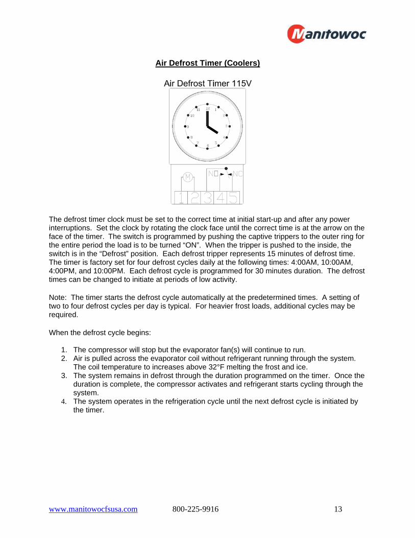
Air Defrost Timer (Coolers)
The defrost timer clock must be set to the correct time at initial start-up and after any power interruptions. Set the clock by rotating the clock face until the correct time is at the arrow on the face of the timer. The switch is programmed by pushing the captive trippers to the outer ring for the entire period the load is to be turned “ON”. When the tripper is pushed to the inside, the switch is in the “Defrost” position. Each defrost tripper represents 15 minutes of defrost time. The timer is factory set for four defrost cycles daily at the following times: 4:00AM, 10:00AM, 4:00PM, and 10:00PM. Each defrost cycle is programmed for 30 minutes duration. The defrost times can be changed to initiate at periods of low activity. Note: The timer starts the defrost cycle automatically at the predetermined times. A setting of two to four defrost cycles per day is typical. For heavier frost loads, additional cycles may be required. When the defrost cycle begins:
1. The compressor will stop but the evaporator fan(s) will continue to run. 2. Air is pulled across the evaporator coil without refrigerant running through the system.
The coil temperature to increases above 32°F melting the frost and ice. 3. The system remains in defrost through the duration programmed on the timer. Once the
duration is complete, the compressor activates and refrigerant starts cycling through the system.
4. The system operates in the refrigeration cycle until the next defrost cycle is initiated by the timer.
www.manitowocfsusa.com 800-225-9916 14
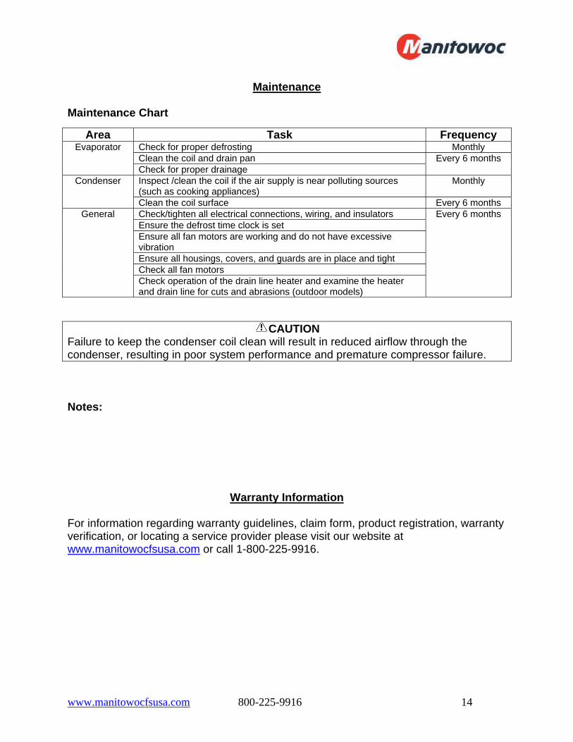
Maintenance
Maintenance Chart
Area Task Frequency Check for proper defrosting Monthly Clean the coil and drain pan
Evaporator
Check for proper drainage Every 6 months
Inspect /clean the coil if the air supply is near polluting sources (such as cooking appliances)
Monthly Condenser
Clean the coil surface Every 6 months Check/tighten all electrical connections, wiring, and insulators Ensure the defrost time clock is set Ensure all fan motors are working and do not have excessive vibration Ensure all housings, covers, and guards are in place and tight Check all fan motors
General
Check operation of the drain line heater and examine the heater and drain line for cuts and abrasions (outdoor models)
Every 6 months
CAUTION Failure to keep the condenser coil clean will result in reduced airflow through the condenser, resulting in poor system performance and premature compressor failure. Notes:
Warranty Information
For information regarding warranty guidelines, claim form, product registration, warranty verification, or locating a service provider please visit our website at www.manitowocfsusa.com or call 1-800-225-9916.

www.manitowocfsusa.com 800-225-9916 15
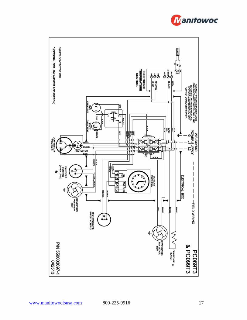
Wiring Diagrams

www.manitowocfsusa.com 800-225-9916 16
www.manitowocfsusa.com 800-225-9916 17
www.manitowocfsusa.com 800-225-9916 18

www.manitowocfsusa.com 800-225-9916 19

www.manitowocfsusa.com 800-225-9916 20

www.manitowocfsusa.com 800-225-9916 21
www.manitowocfsusa.com 800-225-9916 22