drift and breakup of spiral waves in reaction–diffusion ... · reaction–diffusion–mechanics...
TRANSCRIPT
Corrections
BIOPHYSICS. For the article ‘‘Drift and breakup of spiral waves inreaction–diffusion–mechanics systems,’’ by A. V. Panfilov, R. H.Keldermann, and M. P. Nash, which appeared in issue 19, May8, 2007, of Proc Natl Acad Sci USA (104:7922–7926; first pub-lished April 27, 2007; 10.1073�pnas.0701895104), the authorsnote that on page 7922, right column, the first sentence inMathematical Model, ‘‘Our RDM model is based on a three-variable Fenton–Karma RD model for cardiac excitation (15),coupled with the soft-tissue mechanics equations described inrefs. 12 and 16 . . . , where �(x) is the standard Heaviside stepfunction: �(x) � 1 for x � 0 and �(x) � 0 for x � 0,’’ shouldinstead read: ‘‘Our RDM model consists of RD equationsdeveloped by F. H. Fenton (personal communication) and isbased on a three-variable Fenton–Karma RD model for cardiacexcitation (15), coupled with the soft-tissue mechanics equationsdescribed in refs. 12 and 16 . . . , where �(x) is the standardHeaviside step function: �(x) � 1 for x � 0 and �(x) � 0 for x� 0.’’ Additionally, on page 7923, left column, beginning on line10 of the text, the formula for Isi is incorrect in part. The portionof the formula appearing as ‘‘(0.46 � 0.085 � tanh[k(u � 0.5)])’’should instead appear as: ‘‘(0.23 � 0.085tanh[10(u � 0.65)]).’’Thus, the corrected formula should read Isi(u, w) � �(u �0.2)uw(0.23 � 0.085tanh[10(u � 0.65)]). Finally, on page 7926,in the first sentence of the Acknowledgments, the authors wouldlike to more specifically acknowledge the assistance of Dr.Fenton. Therefore, ‘‘We thank Dr. F. Fenton, Prof. P. J. Hunter,and Dr. P. Kohl for valuable discussions’’ should instead read:‘‘We are grateful to Dr. F. H. Fenton, who kindly providedequations used in the construction of our RDM model, and toProf. P. J. Hunter and Dr. P. Kohl for valuable discussions.’’These errors do not affect the conclusions of the article.
www.pnas.org�cgi�doi�10.1073�pnas.0710559104
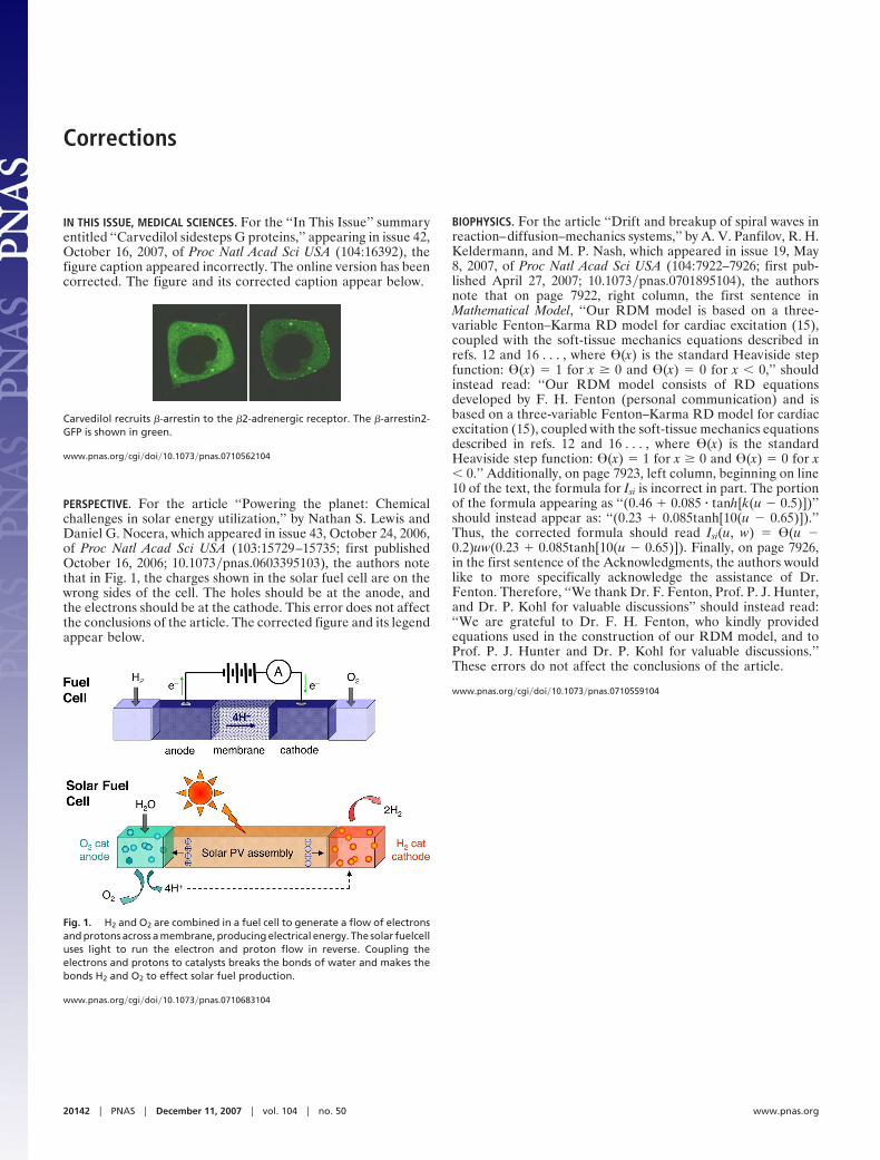
IN THIS ISSUE, MEDICAL SCIENCES. For the ‘‘In This Issue’’ summaryentitled ‘‘Carvedilol sidesteps G proteins,’’ appearing in issue 42,October 16, 2007, of Proc Natl Acad Sci USA (104:16392), thefigure caption appeared incorrectly. The online version has beencorrected. The figure and its corrected caption appear below.
Carvedilol recruits �-arrestin to the �2-adrenergic receptor. The �-arrestin2-GFP is shown in green.
www.pnas.org�cgi�doi�10.1073�pnas.0710562104
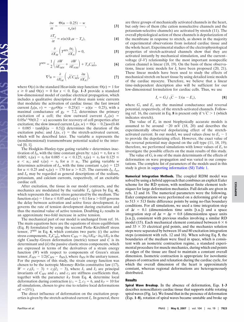
PERSPECTIVE. For the article ‘‘Powering the planet: Chemicalchallenges in solar energy utilization,’’ by Nathan S. Lewis andDaniel G. Nocera, which appeared in issue 43, October 24, 2006,of Proc Natl Acad Sci USA (103:15729–15735; first publishedOctober 16, 2006; 10.1073�pnas.0603395103), the authors notethat in Fig. 1, the charges shown in the solar fuel cell are on thewrong sides of the cell. The holes should be at the anode, andthe electrons should be at the cathode. This error does not affectthe conclusions of the article. The corrected figure and its legendappear below.
Fig. 1. H2 and O2 are combined in a fuel cell to generate a flow of electronsand protons across a membrane, producing electrical energy. The solar fuelcelluses light to run the electron and proton flow in reverse. Coupling theelectrons and protons to catalysts breaks the bonds of water and makes thebonds H2 and O2 to effect solar fuel production.
www.pnas.org�cgi�doi�10.1073�pnas.0710683104
20142 � PNAS � December 11, 2007 � vol. 104 � no. 50 www.pnas.org

Drift and breakup of spiral waves inreaction–diffusion–mechanics systemsA. V. Panfilov*†, R. H. Keldermann*, and M. P. Nash‡
*Department of Theoretical Biology, Utrecht University, Padualaan 8, Utrecht 3584 CH, The Netherlands; and ‡Bioengineering Institute andDepartment of Engineering Science, University of Auckland, Auckland, New Zealand
Communicated by Charles S. Peskin, New York University, New York, NY, March 3, 2007 (received for review January 24, 2006)
Rotating spiral waves organize excitation in various biological,physical, and chemical systems. They underpin a variety of impor-tant phenomena, such as cardiac arrhythmias, morphogenesisprocesses, and spatial patterns in chemical reactions. Importantinsights into spiral wave dynamics have been obtained fromtheoretical studies of the reaction–diffusion (RD) partial differen-tial equations. However, most of these studies have ignored thefact that spiral wave rotation is often accompanied by substantialdeformations of the medium. Here, we show that joint consider-ation of the RD equations with the equations of continuummechanics for tissue deformations (RD–mechanics systems), yieldimportant effects on spiral wave dynamics. We show that defor-mation can induce the breakup of spiral waves into complexspatiotemporal patterns. We also show that mechanics leads tospiral wave drift throughout the medium approaching dynamicalattractors, which are determined by the parameters of the modeland the size of the medium. We study mechanisms of these effectsand discuss their applicability to the theory of cardiac arrhythmias.Overall, we demonstrate the importance of RD–mechanics systemsfor mathematics applied to life sciences.
electromechanics � nonlinear dynamics � stretch-activated channels �cardiac arrhythmias
Rotating spiral waves have been found in a wide variety ofnonlinear systems in physics, chemistry, and biology. For
example, they occur in Belousov–Zhabotinsky (BZ) chemicalreactions (1, 2) and on platinum surfaces during the process ofcatalytic oxidation of carbon monoxide (3). Biological examplesof spiral waves include spiral waves during morphogenesis of theDictyostelium discoideum amoebae (4), spiral waves of calcium-induced calcium release in Xenopus oocytes (5), and spiral wavesin retinal and cortical nerve tissue (2). Another importantexample is in the heart, for which spiral waves of electricalactivity are thought to lead to life-threatening cardiac arrhyth-mias (2, 6).
Spiral waves have been studied extensively by using mathe-matical modeling. In this context, spiral waves are solutions ofthe reaction–diffusion (RD) equations in two dimensions. Thereare a wide range of analytical and numerical approaches to studythe basic features of these systems, as well as specific models fora variety of biological or chemical processes.
Spiral wave rotation typically is accompanied by other importantprocesses. One of the most fundamental is the mechanical defor-mation of the medium. For example, spiral waves during D.discoideum morphogenesis are relayed by chemotactically movingcells (4), and chemical spiral waves in BZ reaction cause deforma-tion of the medium in which they rotate (7). In the heart, theelectrical waves initiate muscle contraction, resulting in substantiallocal deformations. These deformations in turn affect the processof wave propagation in the heart, which is known as the phenom-enon of mechano-electrical feedback. Mechano-electrical feedbackhas been studied in electrophysiology for over a century (seereviews in ref. 8) and may have both anti- and pro-arrhythmicconsequences. Although deformation is known to be important inthe above-mentioned systems, most previous theoretical and ex-
perimental studies have not addressed the combined effects ofmedium mechanics and spiral wave dynamics.
To study the interactive effects of deformation and RDsystems, one needs to combine two classes of partial differentialequations: the RD equations (as above) and the equations ofcontinuum mechanics, which govern the deformation of themedium. Furthermore, one must define the feedback relationsthat exist between them. In the heart, local deformations of upto 10–15% have been observed experimentally (9), thus finitedeformation elasticity theory must be used to describe the tissuemechanics. The detailed coupling of the RD processes andmechanical deformations is complex and not completely under-stood; however, general relationships have been established. Forexample, it is well known that heart tissue contraction is initiatedby an influx of calcium ions into the cardiac myocytes, which isa typical state variable of biophysical RD models (10). On theother hand, deformation changes the geometry of cardiac cellsand ionic currents through the cardiac membrane [via stretch-activated channels (11)], thereby affecting the parameters of theRD system. We have proposed the concept of a RD–mechanics(RDM) system (12), which combines a very general descriptionof deformation with a low-dimensional RD system to study thebasic effects of mechanics on nonlinear wave propagation.
In this article, we apply our RDM modeling approach to studythe fundamental effects of deformation on spiral wave dynamics.We find two types of dynamics: mechanically induced breakup ofspiral waves and drift of spiral waves toward dynamical attractorscaused by mechanical deformation. These types of dynamics maybe important in many applications. For example, in cardiactissue, spiral breakup is considered as a likely mechanism ofventricular fibrillation, whereas meander and drift of spiralwaves are believed to determine the type of cardiac arrhythmia(13, 14).
Mathematical ModelOur RDM model is based on a three-variable Fenton–KarmaRD model for cardiac excitation (15), coupled with the soft-tissue mechanics equations described in refs. 12 and 16:
�u�t
� �2u � Ifi�u, v� � Iso�u� � Isi�u, w� � Is�u, C�, [1]
�v�t
���uc � u� � v
�v�u�, [2]
Author contributions: A.V.P. and M.P.N. designed research; A.V.P. and R.H.K. performedresearch; and A.V.P., R.H.K., and M.P.N. wrote the paper.
The authors declare no conflict of interest.
Abbreviations: RD, reaction–diffusion; RDM, RD–mechanics; BZ, Belousov–Zhabotinsky;[t.u.], dimensionless time units; [s.u.], dimensionless space units.
†To whom correspondence should be addressed. E-mail: [email protected].
This article contains supporting information online at www.pnas.org/cgi/content/full/0701895104/DC1.
© 2007 by The National Academy of Sciences of the USA
7922–7926 � PNAS � May 8, 2007 � vol. 104 � no. 19 www.pnas.org�cgi�doi�10.1073�pnas.0701895104
�w�t
���u � 0.25� � w
�w�u�, [3]
�Ta
�t� ��u��kTu � Ta�, [4]
�
�XM�TMN
�xj
�XN� � 0, [5]
TMN �12 � �W
�EMN�
�W�ENM
� � TaCMN�1 , [6]
�2u ��
�XM��CCMN
�1 �u�XN
�, [7]
where �(x) is the standard Heaviside step function: �(x) � 1 forx � 0 and �(x) � 0 for x � 0. Eqs. 1–3 provide a standardlow-dimensional model of cardiac electrical propagation, whichincludes a qualitative description of three main ionic currentsthat modulate the activation of cardiac tissue: the fast inwardcurrent Ifi(u, v) � �gfiv�(u � 0.25)(1 � u)(u � 0.25), with amaximal conductance of gfi � 7.2, determines the primaryexcitation of a cell; the slow outward current Iso(u) �0.05u1.4�(0.2 � u) accounts for recovery of cell properties afterexcitation; the slow inward current Isi(u, w) � �(u � 0.2)uw(0.46 0.085 � tanh[k(u � 0.5)]) determines the duration of theexcitation pulse; and Is(u, c) � the stretch-activated current,which will be described later. The variable u represents the(nondimensional) transmembrane potential scaled to the inter-val [0, 1].
The Hodgkin–Huxley-type gating variable v determines inac-tivation of Ifi, with the time constant given by: �v(u) � �1 for u �0.085; �v(u) � �2 for 0.085 � u � 0.125; �v(u) � �3 for 0.125 �u � uc; and �v(u) � �4 for u � uc. The gating variable wdetermines activation of Isi, with the time constant �w(u) � 125for u � 0.25 and �w(u) � 170 for u 0.25. The currents Ifi, Iso,and Isi may be regarded as general descriptions of the sodium,potassium, and calcium currents, respectively, of an excitablecardiac cell.
After excitation, the tissue in our model contracts, and themechanics are modulated by the variable Ta (given by Eq. 4),which represents the active stress generated by the medium. Thefunction �(u) � 1 for u � 0.05 and �(u) � 0.1 for u 0.05 governsthe delay between activation and active force development. kTgoverns the rate of tension development during excitation andthus the maximal value of active tension. Doubling kT results inan approximate two-fold increase in active tension.
The mechanical part of our model is unchanged from ref. 16.The main equations here are the equations of stress equilibrium(Eq. 5) formulated by using the second Piola–Kirchhoff stresstensor, TMN in Eq. 6, which contains two parts: (i) the activestress components, TaCMN
�1 , where CMN � �xk/�XM � �xk/�XN is theright Cauchy–Green deformation (metric) tensor and C is itsdeterminant and (ii) the passive elastic stress components, whichare expressed in terms of the derivatives of a strain energyfunction (W) with respect to components of Green’s straintensor, EMN � 1/2(CMN � MN), where MN is the unitary tensor.For the purposes of this study, the strain energy function waschosen to be the isotropic Mooney–Rivlin constitutive law (17),W � c1(I1 � 3) c2(I2 � 3), where I1 and I2 are principalinvariants of CMN and c1 and c2 are stiffness coefficients that,together with the parameter kT from Eq. 4, determine localdeformation during contraction (c1 � 2, c2 � 6, and kT � 10 forall simulations, chosen to give rise to relative local deformationsof �15%).
The direct influence of deformation on the excitation prop-erties is given by the stretch-activated current Is. In general, there
are three groups of mechanically activated channels in the heart,but only two of them (the cation nonselective channels and thepotassium-selective channels) are activated by stretch (11). Theoverall physiological action of these channels is depolarization ofthe membrane in response to stretch, as shown in the majorityof experimental observations from isolated cardiac tissue andthe whole heart. Experimental studies of the electrophysiologicalproperties of stretch-activated channels show that they areactivated instantly by mechanical stimulation, and the current–voltage (I–V) relationship for the most important nonspecificcation channel is linear (18, 19). On the basis of these observa-tions, linear ionic models for Is have been proposed (20, 21).These linear models have been used to study the effects ofmechanical stretch on heart tissue by using detailed ionic modelsof the cardiac myocyte. Therefore, we believe that a lineartime-independent description also will be sufficient for ourlow-dimensional formulation for cardiac cells. Thus, we use
Is � Gs��C � 1��u � Es�, [8]
where Gs and Es are the maximal conductance and reversalpotential, respectively, of the stretch-activated channels. Follow-ing ref. 16, the current in Eq. 8 is present only if �C 1 (whichindicates stretch).
The value of Es in most biophysically accurate models isassumed to be around �20 mV (18, 20) and describes theexperimentally observed depolarizing effect of the stretch-activated current. In our model, we used values close to Es 1to provide the depolarizing effect. However, the exact value ofthe reversal potential may depend on the cell type (11, 18, 19);therefore, we performed simulations with lower values of Es toinvestigate the possible effects on the main results of this study.
The value of Gs is one of the main determinants of the effects ofdeformation on wave propagation and was varied in our compu-tations. The complete list of parameters of the models used in thisstudy is given in supporting information (SI) Table 1.
Numerical Integration Methods. The coupled RDM model wassolved by using a hybrid approach that combines an explicit Eulerscheme for the RD system, with nonlinear finite element tech-niques for large deformation mechanics. Full details are given inrefs. 12 and 16. The numerical parameters were the following.Euler computations were performed on a deforming grid of upto 513 � 513 finite difference points by using no-flux boundaryconditions. For all simulations, we used a time integration stepof �t � 0.1 (dimensionless time units [t.u.]) and a spaceintegration step of �x � �y � 0.8 (dimensionless space units[s.u.]), consistent with previous studies involving a similar RDmodel (15). Each mechanical element contained between 6 � 6and 33 � 33 electrical grid points, and the mechanics solutionsteps were separated by between 10 and 80 excitation integrationsteps (consistent with refs. 12 and 16). When solving Eq. 5, theboundaries of the medium were fixed in space, which is consis-tent with an isometric contraction regime, a standard experi-mental procedure for muscle mechanics, during which end pointsor edges of the tissue are fixed to maintain a constant overalldimension. Isometric contraction is appropriate for isovolumicphases of contraction and relaxation during the cardiac cycle, forwhich the overall dimension of the heart is approximatelyconstant, whereas regional deformations are heterogeneouslydistributed.
ResultsSpiral Wave Breakup. In the absence of deformation, Eqs. 1–3describes nonoscillatory cardiac tissue that supports stable rotatingspiral waves (Fig. 1a). We found that in the presence of deformation(Eqs. 1–8), rotation of spiral waves became unstable and broke up
Panfilov et al. PNAS � May 8, 2007 � vol. 104 � no. 19 � 7923
BIO
PHYS
ICS

into complex spatiotemporal patterns (Fig. 1b) that persisted for theduration of our simulations (�50 rotations).
We investigated the factors underpinning the transition froma stable rotating spiral into spiral breakup. In Eqs. 1–3, the maininfluence of mechanical deformation on excitation appears intwo ways: (i) via the stretch-activated current Is in Eq. 1 and (ii)caused by deformation of the tissue, as expressed in Eq. 7. Westudied the relative contributions of these two factors to thespiral wave instability. We performed one simulation using thesame parameter values and initial conditions as the simulation inFig. 1b but in the absence of Is. In this case, spiral wave stabilitypersisted despite the tissue deformations (SI Fig. 6a).
In another simulation, Is was maintained similarly to thecomputation illustrated in Fig. 1b, but the effect of tissuedeformation on wave propagation was neglected [i.e., rather thanby using Eq. 7, the Laplacian was evaluated by using �2u �(�2/�X2) (�2/�Y2), as for the undeformed configuration]. In thiscase, we observed that the onset of spiral breakup, and itssubsequent complexity, was similar to the simulation in Fig. 1b(see SI Fig. 6b).
In additional sets of computations, we found that spiralbreakup occurred only if the conductance of the stretch-activated channel was Gs � 0.028. We found that this thresholdvalue (which we denote as GsTH) was modulated by otherparameters of the model that influence the stretch-activatedcurrent in Eq. 8. If the reversal potential for the stretch-activatedcurrent was decreased to Es � 0.75, then the conductancethreshold for breakup increased to GsTH � 0.039, and a furtherdecrease to Es � 0.5 resulted in GsTH � 0.065. Clearly, decreasingEs in Eq. 8 reduces the magnitude of the stretch-activatedcurrent, and thus a larger value of Gs is necessary for breakup tooccur. The complete dependence of GsTH on Es is illustrated inSI Fig. 7.
The observation that mechanically induced spiral wavebreakup was primarily caused by the stretch-activated currentwas somewhat unexpected, because it is a depolarizing current,and such currents typically promote excitation in cardiac tissue.Thus, we investigated how propagation block could be caused bythe stretch-activated current, and it turns out that the mechanismof this effect is related to the so-called ‘‘accommodation phe-nomenon,’’ whereby the threshold for activation increases as therate of depolarization is decreased. This effect has been studiedin electrophysiology since 1936 (22, 23).
We illustrate this effect by using an example that incorporatesa recent detailed ionic model for human cardiac cells (24). Thismodel uses a widely accepted biophysical description of the
sodium current, for which conductance of the sodium channelsis proportional to the product of activation (m) and inactivation(h, j) gates: INa m3hj. Following the Hodgkin–Huxley approach(23), the dynamics of the gating variables are given by equationsof the form: dm/dt � (m�(u) � m)/�m(u), where the parametersof the voltage-dependent functions m�(u) and �m(u) are fitted toexperimental measurements. Similar exponential relaxationequations are used for the h and j gates. The steady-state valuesm�(u), h�(u), and j�(u) depend on the transmembrane voltageand are shown in Fig. 2a. As voltage increases, we see that theactivation gate goes from 0 to 1, and the inactivation gate goesfrom 1 to 0. It is important to note that the inactivation curveapproaches zero at a voltage of around u 0.15, whereas theactivation curve starts to increase for higher values of voltageabove about u 0.25. Thus, if cardiac tissue is depolarized slowlyfrom the resting state u � 0 such that the gating variablesapproximately follow their steady-state values, then INa will beinactivated (at u � 0.15) before the voltage reaches the activationthreshold (u � 0.25). A similar situation will occur if cardiactissue is incompletely repolarized after excitation such that theresting potential is above the inactivation value of u � 0.15. Thistype of INa inactivation occurs in our simulations and results inspiral wave breakup.
This finding is illustrated in Fig. 3a, which shows the timecourse of the transmembrane voltage u, the Fenton–Karmavariable v (which accounts for inactivation of the fast inwardcurrent Ifi), and the currents Ifi and Is at a point where the waveblock occurs (marked by the filled square in Fig. 3b). Thehorizontal pink lines in Fig. 3 a Upper and c show the voltageabove which Ifi is inactivated by the v gating variable (u � 0.15).Because Ifi is responsible for excitation and thus wave propaga-tion, inactivation of Ifi results in wave block.
Now let us explain the onset of new wave breaks. During spiralwave rotation (Fig. 3 a Upper and c Inset), we see that theminimal diastolic value of the transmembrane potential initiallyis slightly below the pink (inactivation) line, resulting in recoveryof the variable v up to values of �0.6 (Fig. 3a Lower), whichallows recovery of Ifi required for generation of a new actionpotential. However, we also observed that the minimal diastolicvoltage increased, and after the third action potential thetransmembrane potential did not decrease below the inactivationvalue. As a result, the inactivation variable v was not recoveredand remained at zero, and thus Ifi did not recover as well (aroundthe vertical dashed line in Fig. 3a Lower). In the absence of thefast inward current, excitation is not possible, and wave propa-gation was blocked. This nonrecovery of the transmembrane
Fig. 1. Spiral wave breakup caused by mechanical activity. (a) Spiral waverotation in a RD system based on Eqs. 1–3 and in the absence of deformationwith uc � 0.15, �1 � �2 � �3 � 30, and �4 � 3. (b) Similar computations in adeforming medium using Eqs. 1–8 with Gs � 0.03. Both snapshots are taken at1,800 [t.u.]. The medium consists of 513 � 513 grid points and 16 � 16mechanical elements, each containing 33 � 33 grid points.
Fig. 2. Breakup in a model with biophysical activation and inactivation of thefast inward current Ifi. (a) The scaled activation and inactivation curves fromthe TNNP model (24) (black lines). (The values are scaled from the originalvalues of voltage to the interval of voltage between 0 and 1 for the Fenton–Karma model.) Plotted are the scaled curves of h�(u) � j�(u) (solid black line)and of m3
�(u) (dashed black line) from ref. 24. The gray lines show theHeaviside description of the activation (dashed gray line) and inactivation(solid gray line) curves in Eqs. 1–3. (b) Spiral wave breakup in a model withbiophysical activation and inactivation of the fast inward current Ifi (see textfor details). The snapshot is taken at 1,200 [t.u.], gfi � 14.2, and all otherparameters and initial conditions are the same as in Fig. 1.
7924 � www.pnas.org�cgi�doi�10.1073�pnas.0701895104 Panfilov et al.

potential was caused by the stretch-activated current. We can seethat Is was maximal during the late repolarization phase, whichprevented the voltage from decreasing below the pink line. Toconfirm this effect, we performed a similar simulation but withIs blocked (Fig. 3d). In this case, repolarization continued belowthe inactivation threshold. Thus, the Ifi current was not inacti-vated, and the spiral wave did not break up.
The breakup we observed was caused by sodium currentinactivation. However, although the representation of the so-dium current in the Fenton–Karma model provides a qualita-tively correct description of the activation–inactivation proper-ties of this current, it is not based on experimental data of theseprocesses. To underline the importance of the activation–inactivation processes for our mechanisms, we developed amodification of the Fenton–Karma model, which included bio-physically based activation and inactivation curves of the fastsodium current. We replaced the Heaviside-based activationfunction �(u � 0.25)(u � 0.25) from Eq. 1 with the activationcurve (m3) from the TNNP model (24), scaled to the interval[0, 1] (Fig. 2a) and the Heaviside inactivation function �(uc � u)from Eq. 2 with the voltage-dependent inactivation curve h � j(Fig. 2a). Thus, in this modified model, activation and inactiva-tion processes are based on experimentally measured propertiesof the sodium current. We studied spiral wave rotation with thismodel and found that with these modifications we also obtainedmechanically induced breakup of the spiral wave. As in the caseof the Fenton–Karma model, after a few rotations the spiralwave broke down into a complex spatiotemporal pattern (Fig.2b). Overall, the breakup process was similar to that observed inthe Fenton–Karma model; however, our modification of Ifiresulted in some increase in the wavelength of the spiral waves.
Spiral Wave Drift. We studied the dynamics of spiral wave rotationby using parameter values for which spiral breakup was absent inthe absence of deformation. Under these conditions, the spiralwave rotation was stationary with a circular motion of the spiraltip (Fig. 1a). Using the same parameter values in the presenceof mechanical activity, we observed drift of the spiral wave to thecenter of the medium (Fig. 4a) and subsequent meander of thespiral around the center. The meander pattern in Fig. 4a was acombination of two motions: a counterclockwise rotation of thespiral wave tip along a circular trajectory (similar to that in Fig.1a), with the motion of the center of rotation of this circle after
another circular trajectory in the clockwise direction. This tiptrajectory was reproduced accurately in the complex plane Z �X iY (up to initial phases) by using:
Z�t� � R0 exp� i2f0t� � R1 exp� � i2f1t� . [9]
Eq. 9 describes a cycloidal motion that is a superposition of aclockwise spiral wave rotation with frequency f0 along a circle ofradius R0 and a counterclockwise circular motion along theradius R1 with frequency f1. For Fig. 4a, these parameters areR0 � 7.50 [s.u.], f0 � 11.95 � 10�3 [t.u.]�1, R1 � 4.86 [s.u.], f1 �0.56 � 10�3 [t.u.]�1. We performed several simulations withdifferent initial spiral wave locations, and in all cases, the spiralwave approached the center of the medium and meanderedalong a similar trajectory to that in Fig. 4.
We also have studied how the size of the medium affects spiralwave drift. Fig. 4b illustrates the behavior of a spiral wave in alarger medium (151 � 151 grid points, compared with the 141 �141 grid in Fig. 4b). In this case, the spiral wave also drifted tothe center, but its meander pattern was of larger overall dimen-sion. This meander also was reproduced by using Eq. 9 with R0 �7.50 [s.u.], f0 � 11.95 � 10�3 [t.u.]�1, R1 � 10.67 [s.u.], f1 � 0.37 �10�3 [t.u.]�1. Thus, the change in medium size did not affect thespiral wave rotation (R0 and f0 are the same for Fig. 4 a and b);however, the radius and the period of the circular meandertrajectory were greater for the larger medium.
Fig. 5a shows the effect of medium size on the characteristicsof the meander pattern. We observed that R0 and f0 remainedconstant, whereas R1 increased and f1 decreased with the in-crease in medium size. As a result, the radius of the meanderpattern increased, and the speed along the circular trajectory2 � R1 � f1 increased only slightly with size (data not shown).
Fig. 3. Mechanism of breakup caused by mechanical activity. (a) Timecourses of voltage u (black trace in Upper), stretch-activated current Is multi-plied by 100 (green trace in Lower), the fast inward current Ifi (blue trace inLower), and the variable v (red trace in Lower), which are responsible for theinactivation of Ifi at the point marked by the filled square in b. The dashed lineis located at 560 [t.u.], and the pink line is at u � 0.15. (b) Fragmentation of thespiral wave, showing the same simulation as in Fig. 1b but at time 560 [t.u.].All parameters and conditions are the same as in Fig. 1b. (c) Magnification ofthe dashed rectangular region from a. (d) A similar computation as in a but inthe absence of Is (Gs � 0 in Eq. 8).
Fig. 4. Spiral wave drift caused by mechanical activity. (a) Initial position ofa spiral wave tip (black circle) and the final state of the spiral wave after 120rotations (shaded image) in a medium containing 141 � 141 grid points with11 � 11 points per mechanics element and Gs � 0.01. The arrow indicates thedirection of spiral wave drift, and the solid curve illustrates the trajectory ofthe spiral tip. (b) A similar simulation to that in a but in a medium containing151 � 151 grid points. Other parameter values were the same as those for Fig.1b, except uc � 0.25, �1 � 95, and �3 � 300.
Fig. 5. Characteristics of meander patterns. (a) R0 and R1 in [s.u.] versusmedium size (in grid points). (b) f0 and f1 in [t.u.]�1 versus medium size.
Panfilov et al. PNAS � May 8, 2007 � vol. 104 � no. 19 � 7925
BIO
PHYS
ICS

In a similar manner to the spiral breakup analysis, we studiedhow this drift was modulated by the two feedback effects ofdeformation: the stretch-activated current Is and the effect oftissue deformation of wave propagation. We observed that driftof the spiral wave occurred in the absence of Is, although themeander pattern was not cycloidal (SI Fig. 8a). However, thedrift speed was much slower than that in Fig. 4a. After 120rotations, the spiral wave had drifted approximately one-third ofthe medium width, whereas by the same time in Fig. 4b, the spiralhad approached and made several rotations about the center ofthe medium. In SI Fig. 8b, we see that Is alone induced drift andmeander of the spiral wave similar to that in Fig. 4a. Thecharacteristics of the meander trajectories also were similar(R0 � 7.36 [s.u.], f0 � 12.07 � 10�3 [t.u.]�1, R1 � 4.23 [s.u.], f1 �0.56 � 10�3 [t.u.]�1), although there was a small increase in thespiral wave frequency f0 and a slight decrease in the radius of thecircular motion R1 compared with that of Fig. 4a. Thus, for theseparameters, we conclude that the dominant factor driving spiraldrift is the stretch-activated current.
We believe that the mechanism of this drift is similar to theresonant drift of spiral waves reported in refs. 25 and 26. Asdemonstrated in ref. 26, a periodical variation of the propertiesof an excitable medium in synchrony with the period of a spiralwave resulted in drift and subsequent stable meandering of thespiral wave tip. In our model, deformation of the medium alsoproduced a periodical modulation of the tissue properties insynchrony with the spiral wave period as a result of the excita-tion–contraction coupling. Thus, the effects of mechanics in thepresent study are likely to be similar to the effects of periodicalforcing during resonant drift, leading to drift and meanderingattractors for spiral wave rotation.
DiscussionWe have demonstrated that deformation has a pronouncedeffect on spiral wave rotation and can induce either breakup ordrift and meander of spiral waves.
By using very general descriptions of the excitation–mechanicsproperties, our modeling has demonstrated that stretch-activated channels can induce spiral wave breakup. This conclu-
sion requires confirmation both experimentally and by usingmodeling studies involving detailed ionic descriptions of cardiactissue. In support of the latter, we have shown that spiral breakupoccurred as a result of inactivation of the fast inward current Ifi,which was caused by diastolic depolarization mediated by thestretch-activated current. Furthermore, the notion that thestretch-activated current can block action potential has beendemonstrated by using the Beeler–Reuter ionic model for ven-tricular cells (20), for which it was shown that increasing theconductance of the stretch-activated current resulted in failureof excitation of cardiac cells (see figure 3 in ref. 20). Note alsothat inactivation of the fast sodium current by depolarization hasbeen observed experimentally (e.g., ref. 23) and reproduced byusing ionic models of cardiac tissue (27), for which it can causeblock of propagation.
We suggest that the mechanism of spiral drift is similar to theresonant drift mechanism. Resonant drift of spiral waves incardiac tissue has not been studied experimentally in biologicaltissues but has been shown to exist in detailed ionic models ofcardiac tissue (28), as well as in experiments involving BZreactions (26). Therefore, it is likely that these effects ofmechanics on spiral wave dynamics also could be reproduced byusing more detailed experimental and modeling studies incardiac tissue and in BZ reaction.
Here, we have presented a general study of spiral wavedynamics in a deforming medium, but many potentially impor-tant factors have been neglected, such as the fibrous anisotropyof cardiac tissue, which is important both for the electrical andmechanical properties of the heart. We chose not to consider thisfactor because the main aim of this study was to investigate thebasic effects of mechanics on a general RD system. The influ-ence of cardiac anisotropy is likely to add additional effects andwill need to be addressed in future studies.
We thank Dr. F. Fenton, Prof. P. J. Hunter, and Dr. P. Kohl for valuablediscussions. This research is funded by The Netherlands Organization forScientific Research Grant 814.02.014. M.P.N. is supported by the Mars-den Fund Council from New Zealand government funding, administeredby the Royal Society of New Zealand.
1. Zaikin AN, Zhabotinsky AM (1970) Nature 225:535–537.2. Winfree AT, Strogatz SH (1984) Nature 311:611–615.3. Imbihl R, Ertl G (1995) Chem Rev 95:697–733.4. Weijer C (2004) Curr Opin Genet Dev 14:392–398.5. Lechleiter J, Girard S, Peralta E, Clapham, D (1991) Science 252:123–126.6. Davidenko JM, Pertsov AM, Salomonsz R, Baxter W, Jalife J (1991) Nature
355:349–351.7. Yoshida R, Takahashi T, Yamaguchi T, Ichijo H (1996) J Am Chem Soc
118:5134–5135.8. Kohl P, Ravens U (2003) Prog Biophys Mol Biol 82:1–266.9. McCulloch AD, Smaill BH, Hunter PJ (1987) Am J Physiol 252:H233–H241.
10. DiFrancesco D, Noble D (1985) Philos Trans R Soc B 307:353–398.11. Kohl P, Hunter PJ, Noble D (1999) Prog Biophys Mol Biol 71:91–138.12. Nash MP, Panfilov AV (2004) Prog Biophys Mol Biol 85:501–522.13. Gray RA, Jalife J, Panfilov A, Baxter WT, Cabo C, Pertsov AM (1995)
Circulation 91:2454–2469.14. Garfinkel A, Qu Z (1999) in Nonlinear Dynamics of Excitation and Propagation
in Cardiac Tissue, eds Zipes DP, Jalife J (Saunders, Philadelphia), pp 315–320.
15. Fenton F, Karma A (1998) Chaos 8:20–47.16. Panfilov AV, Keldermann RH, Nash MP (2005) Phys Rev Lett 95:258104.17. Hunter PJ, Nash MP, Sands GB (1997) in Computational Electromechanics of
the Heart, eds Panfilov AV, Holden AV (Wiley, Chichester, UK), pp 345–407.18. Hu H, Sachs F (1997) J Mol Cell Cardiol 29:1511–1523.19. Zhang Y, Youm J, Sung H, Lee S, Ryu S, Ho W, Earm Y (2000) J Physiol
(London) 523:607–619.20. Vetter F, McCulloch A (2001) Ann Biomed Eng 29:414–426.21. Trayanova N, Li W, Eason J, Kohl P (2004) Heart Rhythm 1:67–77.22. Hill AV (1936) Proc R Soc London 119:305–355.23. Hodgkin AL, Huxley AF (1952) J Physiol (London) 117:500–544.24. ten Tusscher, KHWJ, Noble D, Noble PJ, Panfilov AV (2004) Am J Physiol
286:H1573–H1589.25. Agladze KI, Davydov VA, Mikhailov AS (1987) JETP Lett 45:767–769.26. Grill S, Zykov VS, Muller SC (1995) Phys Rev Lett 75:3368–3371.27. Biktashev VN (2002) Phys Rev Lett 89:168102.28. Biktashev VN, Holden AV (1995) Proc R Soc London B 260:211–217.
7926 � www.pnas.org�cgi�doi�10.1073�pnas.0701895104 Panfilov et al.