drdo student robot competition - iiit hyderabadbasil.george/files/drdo.pdfdrdo student robot...
TRANSCRIPT
DRDO Student Robot Competition
International Institute of Information Technology - Hyderabad
Team IIITTeam IIITTeam IIITTeam IIIT----HyderabadHyderabadHyderabadHyderabadDRDO 2010
1
Introduction
2
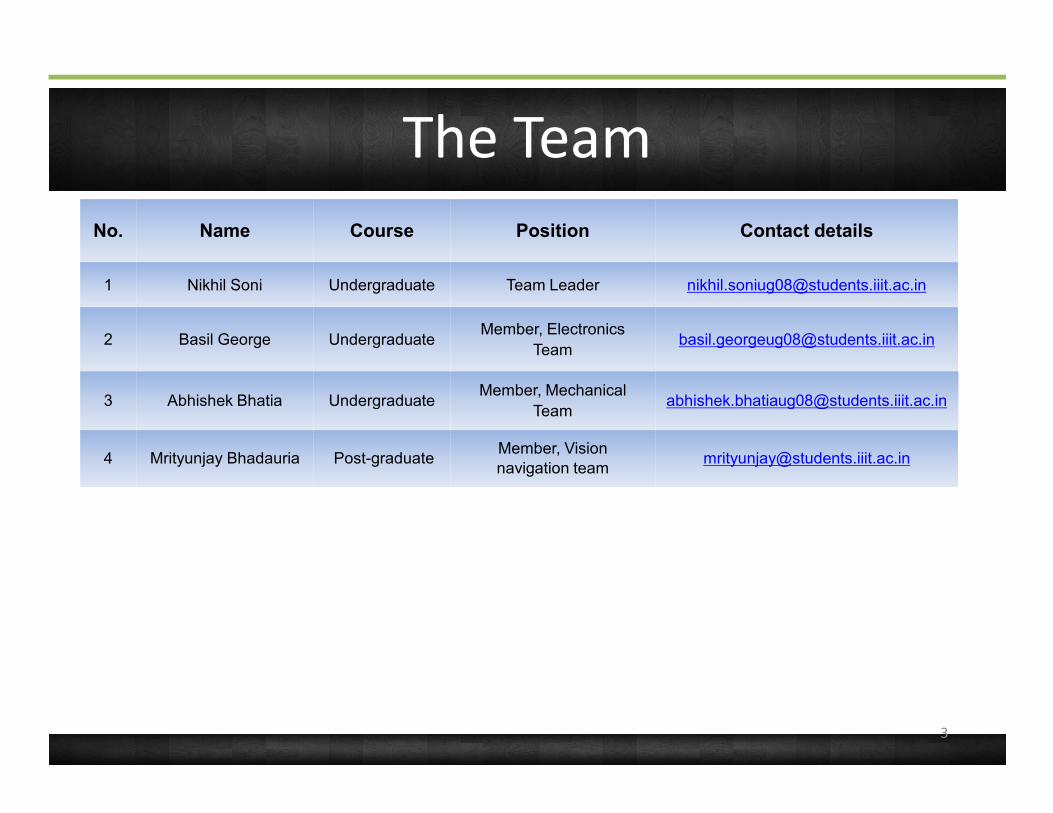
The TeamNo. Name Course Position Contact details
1 Nikhil Soni Undergraduate Team Leader [email protected]
2 Basil George UndergraduateMember, Electronics
3 Abhishek Bhatia UndergraduateMember, Mechanical
[email protected] Abhishek Bhatia Undergraduate
4 Mrityunjay Bhadauria Post-graduateMember, Vision navigation team
3

Organisation Chart
Team MentorMr. Ravi Prasad
Faculty Advisor
Electronics DesignTeam:
Lead : Nikhil SoniBasil GeorgeFaculty Advisor
Dr. K. Madhava Krishna
Team LeaderNikhil Soni
Alternate Team LeaderMrityunjay Bhadauria
Basil George
Mechanical Structure:Abhishek Bhatia
Vision Navigation Algorithm:Mrityunjay Bhadauria
4

Introduction
Systems Overview
5
Mission Summary
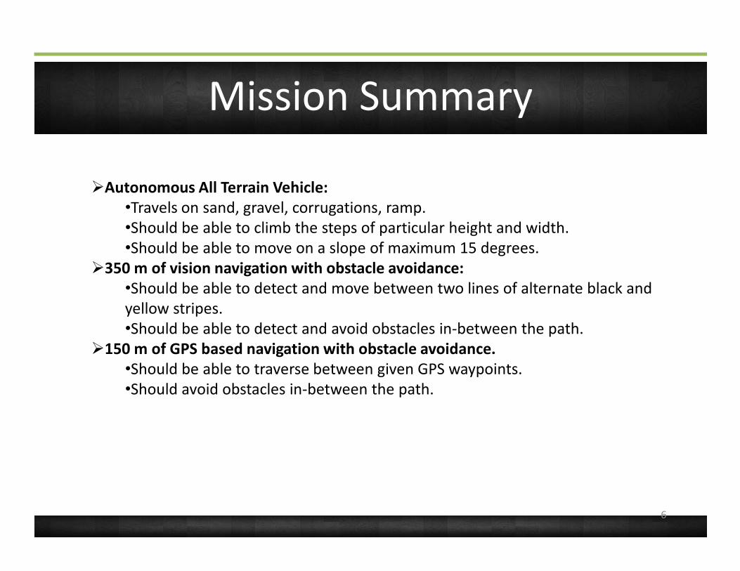
ØAutonomous All Terrain Vehicle: •Travels on sand, gravel, corrugations, ramp. •Should be able to climb the steps of particular height and width. •Should be able to move on a slope of maximum 15 degrees.
Ø350 m of vision navigation with obstacle avoidance: •Should be able to detect and move between two lines of alternate black and •Should be able to detect and move between two lines of alternate black and yellow stripes. •Should be able to detect and avoid obstacles in-between the path.
Ø150 m of GPS based navigation with obstacle avoidance. •Should be able to traverse between given GPS waypoints. •Should avoid obstacles in-between the path.
6

Overview of Changes since PDR
ØMechanical Design:•4 wheel drive changed to 6 wheel, with flexible front portion.•The front portion is fixed to the back using aluminum door hinges, which provides a great flexibility to the structure.•This rocker-bogey-inspired structure is fabricated for efficient stair climbing and flexible all terrain navigation.flexible all terrain navigation.
ØCommand and Data handling subsystem:•Main processing unit changed from Beagle-Board (rev.C3, ARM Processor + DSP Processor) to INTEL ATOM NEBOOK for better real time response characteristics.
ØSensor Subsystem:•Stereo Vision Camera is changed to single VGA USB Camera.
7

System Context Diagram
8

Physical Layout
9
Introduction
Systems Overview
Sensor Systems Design
10

Sensor Systems Overview
Sonar1
(LV-MaxSonar –EZ0)
Laptop(Lenovo Ideapad S-10
GPS sensor( SIRF -StarIII GSC3f/LPx-7989)
Microcontroller1 (ATmega16)
Sonar2
(LV-MaxSonar –EZ0)
(Lenovo Ideapad S-10 Netbook)
Digital Compass Module(CMPS03)
11

Summary of Sensor Procurement
(a) GPS Procurement Status
Item Description
Component GPS Sensor iWave-GPS Module with PatchAntenna Chip manufaccture:
12
Antenna Chip manufaccture: Sirf.
Vendor iWave Systems Technology Pvt. Ltd Bangalore.
Quantity 1
Model Procurement IIIT-H Robotics Lab
Unit Cost 4590 Rs.
Comments -

Summary of Sensor Procurement
(b) Sonar
Item Description
Component LV-MaxSonar –EZ0
Vendor Nex Robotics Mumbai.
13
Vendor Nex Robotics Mumbai.
Quantity 2
Date of Order September 10, 2010
Date of Delivery September 16, 2010
Unit Cost 1296 Rs.
Total Cost 2592 Rs.
Comments -
Summary of Sensor Procurement
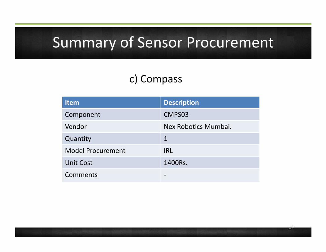
c) Compass
Item Description
Component CMPS03
Vendor Nex Robotics Mumbai.
14
Vendor Nex Robotics Mumbai.
Quantity 1
Model Procurement IRL
Unit Cost 1400Rs.
Comments -

Summary of Sensor Procurement
d) Camera
Item Description
Component Logitech USB VGA Camera
Vendor Croma, Hyderabad
15
Vendor Croma, Hyderabad
Quantity 1
Unit Cost 1400Rs.
Comments -

GPS Summary
Manufacturer Model Dimensions Accuracy Mass Power/voltage
SiRF StarIIIGSC3f/LPx-7989
Length:27mm Width: 23mm
5m 10g 75mw/3.3v
SiRF GSC3 GPS Sensor
• It works at 3.3 V , which we already generated for other requirements using buck converter. Hence it reduces our effort in generating any other voltage. •It has a 20 receiver which was giving a resolution upto 3 m, which was sufficient for our requirement.
16

GPS Measurement Processing
• Four formats of Data (GGA,GSA,GSV,RMC) being received of NMEA protocol through USART to USB adapter.
Receive Extracted values and use it in
Receive GPS valuesand store in array
Read array and Parse relevant data in our case it in
Data packet buffer
and store in array data in our caseGPRMC
Data Frame Format/StructureRecommended Minimum Data (RMC)
$GPRMC,hhmmss.status,latitude.N,longitude,E.spd,cog,ddmmyy,mv.mvE,mode*cs<CR><LF>
$GPRMC suits our requirement of receiving latitude, longitude, speed, number of satellites tracked and Date-Time.
17
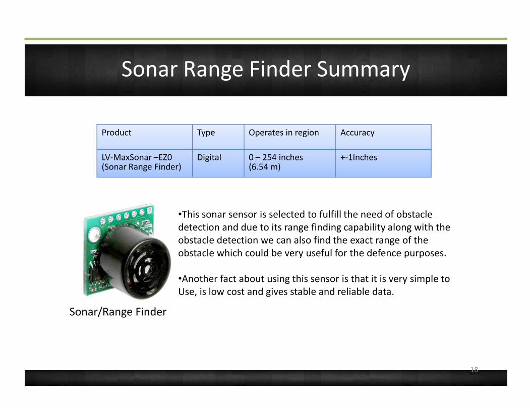
Sonar Range Finder Summary
Product Type Operates in region Accuracy
LV-MaxSonar –EZ0(Sonar Range Finder)
Digital 0 – 254 inches(6.54 m)
+-1Inches
Sonar/Range Finder
•This sonar sensor is selected to fulfill the need of obstacle detection and due to its range finding capability along with the obstacle detection we can also find the exact range of the obstacle which could be very useful for the defence purposes.
•Another fact about using this sensor is that it is very simple to Use, is low cost and gives stable and reliable data.
18

Sonar Range Finder Measurement and Processing
Accept the Analog values from the Collect Continuous Converting the values from the
ADC and convert it to Centigrade from
Digital values obtained
Collect Continuous analog data from
Sonar Range Finder Sensor into the microcontroller.
Converting the Analog voltage value
into digital calibrated value
19

Sonar Range Finder Measurement and Processing
Sonar Range Finder Measurement and Processing
Sonar Range Finder Measurement and Processing
Sonar Range Finder Measurement and Processing
Sonar Range Finder Measurement and Processing(Range shown on 1-foot Grid to various diameter dowels)
20
ProcessingProcessingProcessingProcessing

Compass Sensor Summary
Model Accuracy Mass Power/voltage Dimensions A/D
CMPS03(Philips KMZ51 magnetic field sensor)
1 degrees 50g 0.5ma/5v 2*2cm D
CMPS03 Compass Sensor
• I2C Interface.• Less in weight and size.• Works at 5 V , which is generated for other requirements too.• Digital in nature, thus easy to use with Microcontrollers, directly gives digital magnetic reading.
21
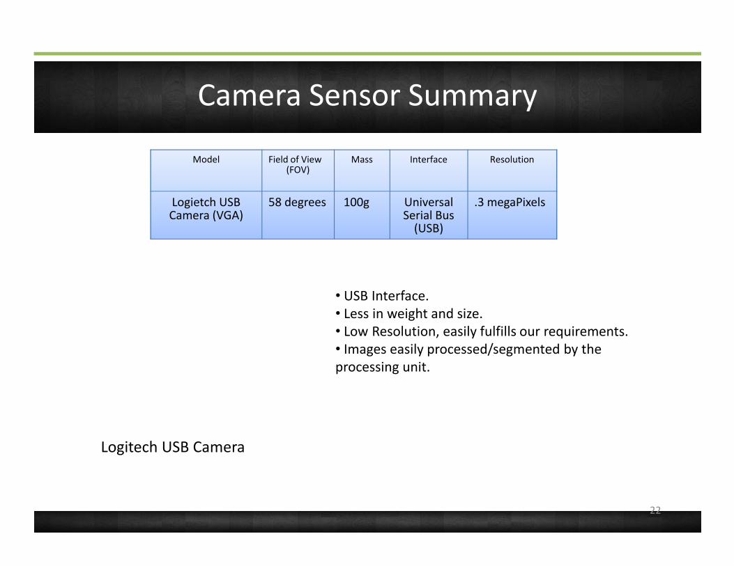
Camera Sensor Summary
Model Field of View(FOV)
Mass Interface Resolution
Logietch USB Camera (VGA)
58 degrees 100g Universal Serial Bus
(USB)
.3 megaPixels
Logitech USB Camera
• USB Interface.• Less in weight and size.• Low Resolution, easily fulfills our requirements.• Images easily processed/segmented by the processing unit.
22
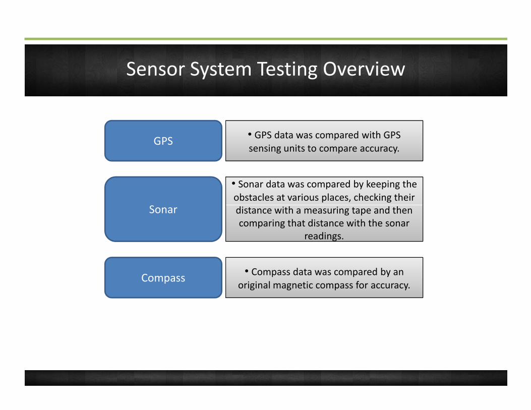
Sensor System Testing Overview
GPS • GPS data was compared with GPS sensing units to compare accuracy.
Sonar
•• Sonar data was compared by keeping the obstacles at various places, checking their distance with a measuring tape and then Sonar
readings.
distance with a measuring tape and then comparing that distance with the sonar
readings.
Compass • Compass data was compared by an original magnetic compass for accuracy.
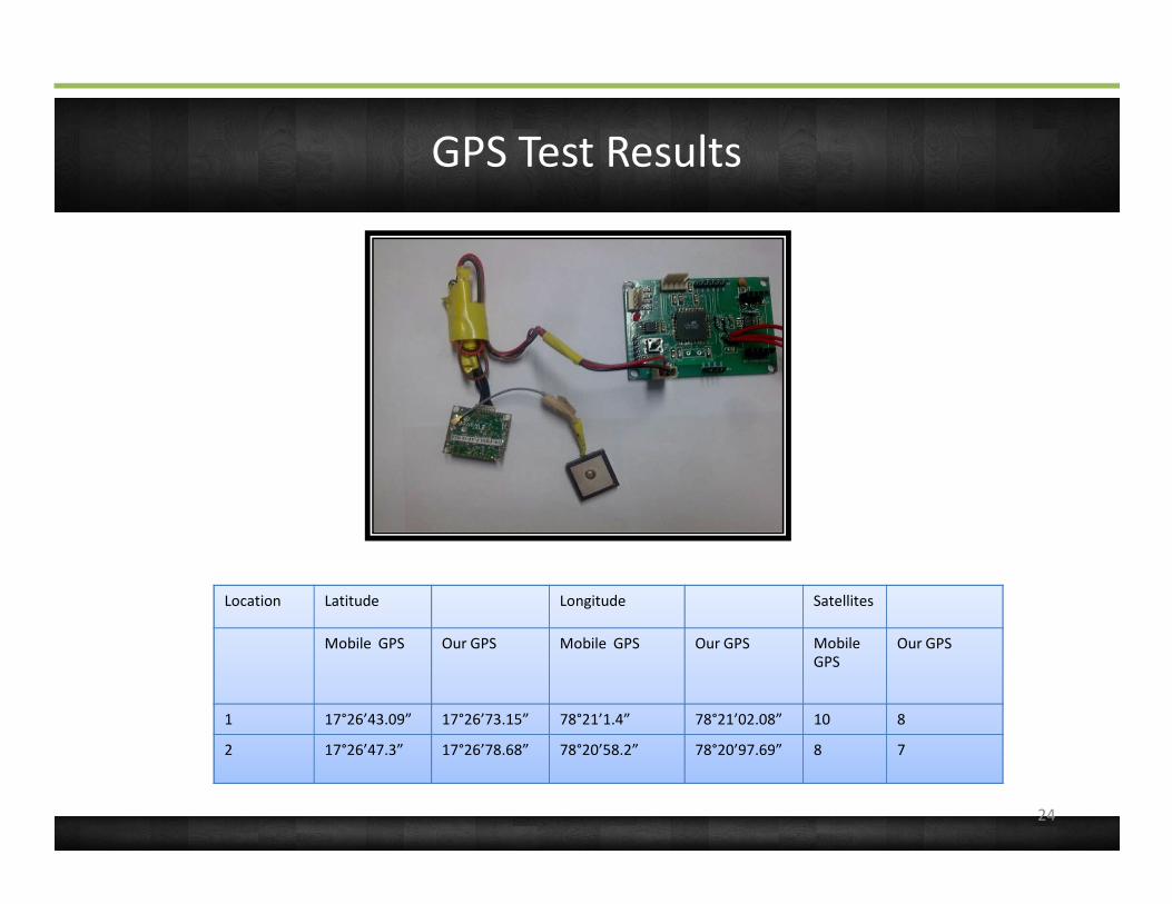
GPS Test Results
Location Latitude Longitude Satellites
Mobile GPS Our GPS Mobile GPS Our GPS Mobile GPS
Our GPS
1 17°26’43.09” 17°26’73.15” 78°21’1.4” 78°21’02.08” 10 8
2 17°26’47.3” 17°26’78.68” 78°20’58.2” 78°20’97.69” 8 7
24
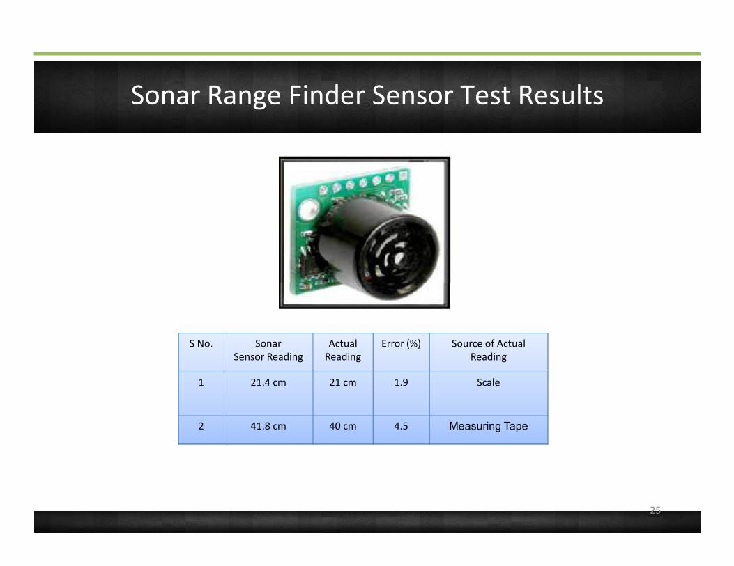
Sonar Range Finder Sensor Test Results
S No. SonarSensor Reading
ActualReading
Error (%) Source of ActualReading
1 21.4 cm 21 cm 1.9 Scale
2 41.8 cm 40 cm 4.5 Measuring Tape
25

Compass Sensor Test Results
S No. SonarSensor Reading
ActualReading
Error (%) Source of ActualReading
1 326 degrees 324 degrees
0.8 Iphone 3GS built in compass
2 40 degrees 41 degrees 0.4 Iphone 3GS built in compass
26

System overview: Interface level
Dual Core Intel Atom
@1.86GHzMCU 1 : Sensor collection
ATmega16 @ 12 MHz
MCU 2 : Motor control
ATmega16 @ 8 MHz
iWave
USB-UARTUSB-UART
USB-UART
27
MHz MHziWaveGPS
CompassLeft
SonarRight Sonar
LeftMotors
Right Motors
Set PWM and rotation logic
Motor driversADC ADCIIC

Introduction
Systems Overview
Sensor Systems Design
Mechanical Systems Design
28

Mechanical Systems Overview
Ø The mechanical subsystem consists of the chassis along with the motors and motor drivers. The mechanical design is inspired from the rocker-bogie suspension system used in Mars rovers.
Ø The design is of a six-wheel drive. The chassis consists of 2 parts: a
29
Ø The design is of a six-wheel drive. The chassis consists of 2 parts: a flexible front portion with 2 wheel’s which Is hinged on a back portion to which 4 wheel’s are attached as shown in the figure:

Mechanical Structure
30

Dimensions:
Ø Wheel diameter: 8inches keeping in mind the maximum step height.
Ø Length of front portion: 30cms. Ø Length of back portion: 50cms.Ø Length between front and middle
31
Ø Length between front and middle wheel = 30cms.
Ø Length between back and middle wheel = 32cms.
Ø Width: 38cms.Ø Weight: 15kg, along with motors and
Wheel’s.

Chassis negotiating a slope
32
Introduction
Systems Overview
Sensor Systems Design
Mechanical Systems Design
Command and Data Handling
33
CDH Overview
This subsystem deals with the processors used in the system, data rate estimation, communication configuration and various protocols employed for inter-processor as well as
34
processor-peripheral device communication.

CDH Overview
• Should implement image processing algorithms in real-time.
• Should handle sensor-data fusion in real-time.
• Require an ADC interface with at • Require an ADC interface with at least 2 ADC ports for SONAR interface.
• Require an I2C interface for digital compass interface.
• Require 1 UART port for GPS interface.
• Should handle power estimated by power budget.
Criterion for microcontroller
selection
35
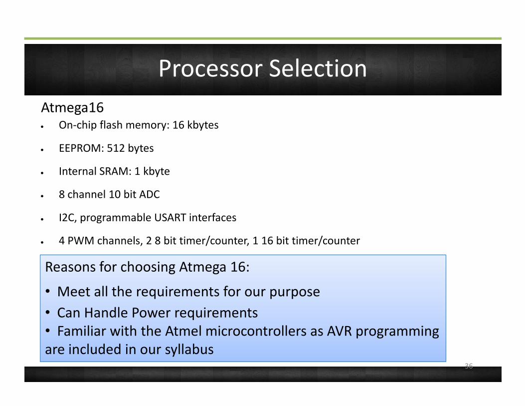
Processor SelectionAtmega16• On-chip flash memory: 16 kbytes
• EEPROM: 512 bytes
• Internal SRAM: 1 kbyte
• 8 channel 10 bit ADC
• I2C, programmable USART interfaces
• 4 PWM channels, 2 8 bit timer/counter, 1 16 bit timer/counter
• 32 programmable I/O pinsOther Processor Considered:
• Atmega 16 : Only one USART ; Less number of I/O ports• 8051 family : Maximum Clock frequency up to 12 MHZ ; Less Memory
Reasons for choosing Atmega 16:
• Meet all the requirements for our purpose • Can Handle Power requirements• Familiar with the Atmel microcontrollers as AVR programming are included in our syllabus
36

Processor Selection
Intel Atom processor is very suitable for mobile robotics applications because its small foam factor and high battery life. The Lenovo Ideapad S10 chosen by us has the following features which makes it suitable for real-time processing include:1.86GHz processor1.86GHz processorRAM: 1GB, DDR3RAM frequency: 1.33GHz3 USB portsOther Processor Considered:
• Though TI Beagleboad's dual core of ARM and DSP was initially considered as the main
processing unit, we discarded it due to its low real-time computation power and higher
delays involved in implementing image processing algorithms. Another reason was its low
community support which made our progress very sluggish.
Other options considered TI Beagle Board:
37
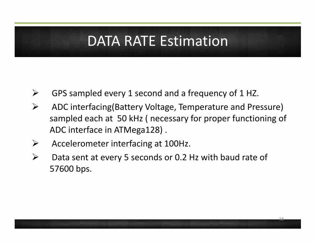
DATA RATE Estimation
Ø GPS sampled every 1 second and a frequency of 1 HZ.Ø ADC interfacing(Battery Voltage, Temperature and Pressure)
sampled each at 50 kHz ( necessary for proper functioning of sampled each at 50 kHz ( necessary for proper functioning of ADC interface in ATMega128) .
Ø Accelerometer interfacing at 100Hz.Ø Data sent at every 5 seconds or 0.2 Hz with baud rate of
57600 bps.
38

Data Package Definition
Characters Definition
hhmmss Data time tag in hours , minutes and seconds
AAAA.aaaa Cansat latitude
N END of latitude data
BBBB.bbbb Cansat Longitude
W END of longitude dataW END of longitude data
hh.hh.. Cansat GPS altitude
Ab Number of satellites tracked in decimal
hh.hh.. Altitude via non GPS sensor(meters)
tt Air temperature ( 1 degree resolution)
vv.v Battery voltage
Total estimated character data including comma delimiters and headers: 60 bytes
39
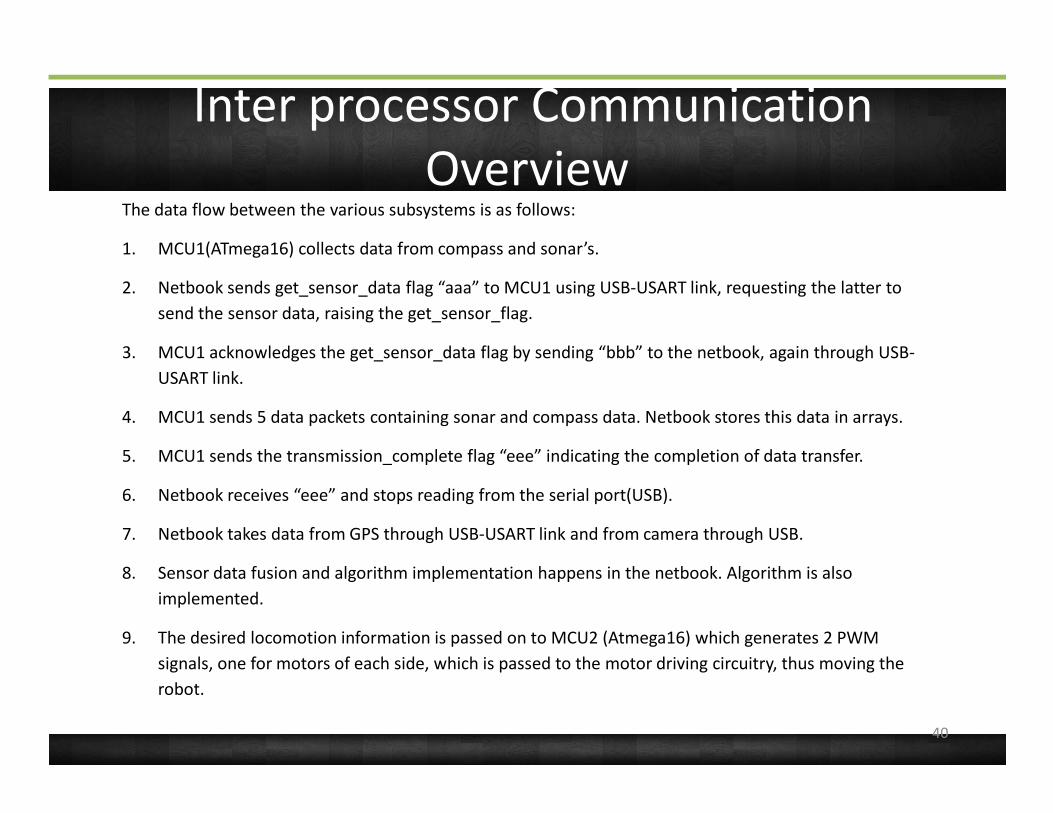
Inter processor Communication Overview
The data flow between the various subsystems is as follows:
1. MCU1(ATmega16) collects data from compass and sonar’s.
2. Netbook sends get_sensor_data flag “aaa” to MCU1 using USB-USART link, requesting the latter to send the sensor data, raising the get_sensor_flag.
3. MCU1 acknowledges the get_sensor_data flag by sending “bbb” to the netbook, again through USB-USART link.
4. MCU1 sends 5 data packets containing sonar and compass data. Netbook stores this data in arrays.
40
4. MCU1 sends 5 data packets containing sonar and compass data. Netbook stores this data in arrays.
5. MCU1 sends the transmission_complete flag “eee” indicating the completion of data transfer.
6. Netbook receives “eee” and stops reading from the serial port(USB).
7. Netbook takes data from GPS through USB-USART link and from camera through USB.
8. Sensor data fusion and algorithm implementation happens in the netbook. Algorithm is also implemented.
9. The desired locomotion information is passed on to MCU2 (Atmega16) which generates 2 PWM signals, one for motors of each side, which is passed to the motor driving circuitry, thus moving the robot.

Introduction
Systems Overview
Sensor Systems Design
Mechanical Systems Design
Command and Data Handling
Electrical Power System Design
41

EPS Overview
Laptop Battery
MCU 1 : Sensor collection
ATmega16 @ 12 MHz
MCU 2 : Motor control
ATmega16 @ 8 MHz
iWave GPS
Compass
Motor driving
USART to USB
42
iWave GPS ModuleLeft
Sonar
Right Sonar
Motor driving unitLinear
Regulator 5V
7.4V Lithium Polymer (Li-Po)
Battery
12V Lead Acid Battery
Powered from the Laptop
Battery (Through USB)

EPS Summary/Budget
Type Voltage/Power Qty Purpose
Lithium Polymer(LiPo) 7.4V/2.2Ah 1 Power logic circuitry
Lead Acid 12V/7Ah 2 Power motors
Summary:
Budget:
43
Component Voltage (V) Current (mA)
Power (mW) Qty Time of usage (%)
SONAR 5 3 15 2 100
Compass 5 25 125 1 100
GPS 3.3 22.7 72.6 1 100
MCU1(12MHz) 5 16 80 1 100
MCU2(8MHz) 5 12 60 1 100
Motor driver 12 1200 14400 6 100
Budget:

EPS Requirements
Ø Logic circuitry:• Power required P1 = 295mW• Time before battery drains out > 37
hours
44
hours Ø Motor driving unit:
• Power required for each lead acid battery P2 = 43.2W
• Time before the batteries drain out = 2 hours
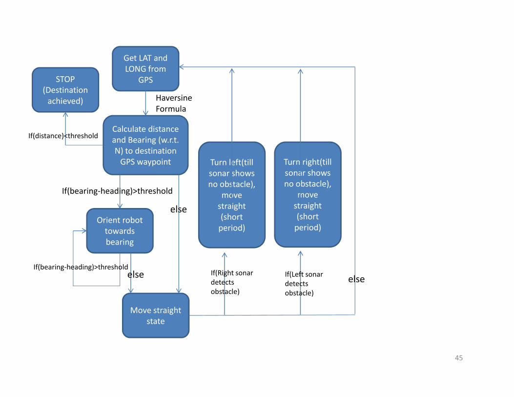
Get LAT and LONG from
GPS
Calculate distance and Bearing (w.r.t. N) to destination
GPS waypoint
Haversine Formula
If(bearing-heading)>threshold
Turn left(till sonar shows no obstacle),
move
Turn right(till sonar shows no obstacle),
move
STOP(Destination
achieved)
If(distance)<threshold
Orient robot towards bearing
If(bearing-heading)>threshold
Move straightstate
else
else
move straight(short
period)
move straight(short
period)
If(Right sonar detects obstacle)
If(Left sonar detects obstacle)
else
45

Introduction
Systems Overview
Sensor Systems Design
Descent Control Design
Mechanical Systems Design
Command and Data Handling
Electrical Power System Design
Conclusions
46

Conclusion
• Though we were lacking in the mechanical front (since our college does not have mechanical branch), we managed to build a robust robot which could navigate sandy and gravel terrains and uneven surfaces with ease.
• We developed and implemented the complete algorithm • We developed and implemented the complete algorithm within the short time-limit given.
47