drawing guide ma nu will rich
TRANSCRIPT

8/2/2019 Drawing Guide Ma Nu Will Rich
http://slidepdf.com/reader/full/drawing-guide-ma-nu-will-rich 1/236

8/2/2019 Drawing Guide Ma Nu Will Rich
http://slidepdf.com/reader/full/drawing-guide-ma-nu-will-rich 2/236
LI BRARYOF THE
UNIVERSITY OF CALIFORNIA.GIRT OR
Received
AccessionsNO._^__^J^^_
. SJulf fto'.._^__

8/2/2019 Drawing Guide Ma Nu Will Rich
http://slidepdf.com/reader/full/drawing-guide-ma-nu-will-rich 3/236

8/2/2019 Drawing Guide Ma Nu Will Rich
http://slidepdf.com/reader/full/drawing-guide-ma-nu-will-rich 4/236

8/2/2019 Drawing Guide Ma Nu Will Rich
http://slidepdf.com/reader/full/drawing-guide-ma-nu-will-rich 5/236

8/2/2019 Drawing Guide Ma Nu Will Rich
http://slidepdf.com/reader/full/drawing-guide-ma-nu-will-rich 6/236

8/2/2019 Drawing Guide Ma Nu Will Rich
http://slidepdf.com/reader/full/drawing-guide-ma-nu-will-rich 7/236
THE
DRAWING GUIDE;A MANUAL OF INSTRUCTION IN
INDUSTRIAL DRAWING,DESIGNED TO ACCOMPANY THE
INDUSTRIAL DRAWING SERIES.
WITH AN INTRODUCTORY ARTICLE ON THE
PRINCIPLES AND PRACTICE OF ORNAMENTAL ART.
BY MARCIUS WILLSOST,ATJTIIOE or "BCUOOL AND FAMILY BEBIES or READEJIS," "MANUAL or OBJECT LESSONS,
ETC., ETC.
UNIVERSITY
HARPER & BROTHERS, PUBLISHERS,
FRANKLIN SQUARE.
1881.

8/2/2019 Drawing Guide Ma Nu Will Rich
http://slidepdf.com/reader/full/drawing-guide-ma-nu-will-rich 8/236
Entered according to Act of Congress, in the year 1873, by
HARPER & BROTHERS,
In the Office of the Librarian of Congress, at Washington.

8/2/2019 Drawing Guide Ma Nu Will Rich
http://slidepdf.com/reader/full/drawing-guide-ma-nu-will-rich 9/236
CONTENTS.Preface Page v
PART I. ORNAMENTAL ART.
I. Introductory 13
II. General Principles of Ornamental Art 18
Prop. I. The Cardinal Principle in Decoration, 18: Prop. II. Of
Angular and Winding Forms, 19: Prop. III. Of Firm and Unbroken,and Fine and Faint Lines, 20 : Prop. IV. Of Construction and Deco-
ration, 21 : Prop.V. Of General Forms, 22 : Prop.VI. Of Geometrical
Construction, 22: Prop.VII. OfMethods of Surface Decoration, 23:
Prop.VIII. Of Proportion in Ornamentation, 24 : Prop. IX. Of Har-
mony and Contrast, 25: Prop. X. Of Distribution, Radiation, and
Continuity,26 :
Prop.XI. Of Conventional
Representationsof Natu-
ral Objects, 27.
III. Ornamental Art among different Nations, and in different Periods of
Civilization 28
I. Ornament of Savage Tribes, 28 : II. Egyptian Ornament, 29 :
III. Assyrian and Persian Ornament, 30 : IV. Greek Ornament, 31 :
V. Pompeian Ornament, 32 : VI. Roman Ornament, 32 : VII.
Byzantine Ornament, 33 : VIII. Arabian Ornament, 34: IX. Turk-
ish Ornament, 35: X. Moresque or Moorish Ornament, 36: XI.
Persian Ornament, 37: XII. East Indian Ornament, 37: XIII.
Hindoo Ornament, 38:
XIV. Chinese Ornament, 38:
XV. CelticOrnament, 39 : XVI. Mediaeval or Gothic Ornament, 39 : XVII.Renaissance Ornament, 41: XVIII. Elizabethan Ornament, 42:
Modern Ornamental Art, 42.
PART II. PRINCIPLES AND PRACTICE OF INDUSTRIALDRAWING.
DRAWING-BOOK No. I.
I. Materials and Directions 47
II. Straight Lines and Plane Surfaces 51
Horizontal and Vertical Lines, 51 : Angles and Plane Figures, 52:
Principles of Surface Measurement, 53 : Rules, 53-61 : Problems,53 : Diagonals, 55 : Problems, 55 : Two-space Diagonals, 57 :
Problems, 59, 60 : Three -space Diagonals, 61 : Problems, 62:
Egyptian Patterns, 66, 67: Arabian, 67, 71, 72 : Byzantine, 67, 69 :
Pompeian, 67: Grecian, 68-72: East Indian, 69: Braided
Work, 68 -.Problems, 64, 66, 68.
III. Curved Lines and Plane Surfaces 73
Regular Curves,73:
Irregular Curves,74:
Symmetrical Figures,75 : Problems, 76 : Conventional Leafage, 77 : Problems, 78 :
Renaissance Ornament, 78: Bulb Pattern, 79: Problems, 79:
Assyrian and Byzantine Patterns, 79-81: Problems, 81: Quarter-
foil, 81: Original Designs, 81.
DRAWING-BOOK No. II.
Cabinet Perspective Plane Solids 84
Diagonal Cabinet Perspective, 84 : Elementary Rule, 85 : Solid
Contents of a Cube Rule, 86 : Parallelepipeds Rule, 87 : Hatch-
ing, 88 : Problems, 89 : Stairs, 90 : Cabinet Frame-work, 91 :

8/2/2019 Drawing Guide Ma Nu Will Rich
http://slidepdf.com/reader/full/drawing-guide-ma-nu-will-rich 10/236
IV CONTENTS.
Problems, 92 : Scarfing, 92 : Problems, 91 : Brick-work, EnglishBond and Flemish Bond, 94 : Problems, 90 : Divisions of the Cube,96 : Solid Frets, 97 : Timber Framing, 97 -.Problems, 97 : Mould-
ings and Cabinet-work, 98: Table, 99
:
Problems, 100: Irregular
Block Forms, 100: Problems, 102: Pyramidal Structures, 102:
Problems,l05 : Fence Frame-work, 1 05 : Problems, 10G : Post-and-
Kail Fence, 106 : Arabian Fret, Solid, 107: Problems, 108: Picket
Fence, Grecian Frets, Chest with Tray, 108, 109 : Problems, 109 :
Solid and Hollow Geometrical Block Forms, 109-111: Bridge-work,112: Cubical Block Patterns, 112 -.Problems, 112.
DPvAWING-BOOK No. III.
Cabinet Perspective Curvilinear Solids 114
Cylinders, Solid, Hollow, and Divided, 114-116: Problems, 116 :
Semicircular Arches, 117: Problems, 118: Braces, Straight and
Curvilinear, 119 : Quarterfoil, 120 : Problems, 121 : Brackets, 121 :
Trefoil and Quarterfoil, 122 -.Problems, 123 -.Conventional Leaf
Pattern, 123: Solid Triangle, 124: Curvilinear and Quadrangular
Solids, 125: Architectural Band, 126: Problems, 126: Rims of
Wheels, 126: Beveled Tub, 127: Hollow Cylinders, 128: IrregularCurved Solids, 128 : Problems, 129 : Curvilinear Frame-works, 129 :
Problems, 131 : Large Wheel, with Spokes, 131 -.Problem, 133 :
Large Wheel, with Spokes and Double Kim, 133 : Crown-wheel, 135 :
Ratchet Wheel, 136 : Windlass, with Spokes, 138.
DRAWING-BOOK No. IV.
Cabinet Perspective Miscellaneous Applications 1 43
I. Different Diagonal Views of Objects 143
II. Ground-Plans and Cabinet-Plans of Buildings 144
Problem, 146 : Series of Platform Structures, 147: Problem, 149.
III. Cylindrical Objects in Vertical Positions 149
I. Ellipses on Diagonal Bases 150
II. Ellipses on Rectangular Bases152
Ellipses in Vertical Positions, 153 : Rule, 155 : Problems, 155:
Hollow Cylinders, 156 -.Problems, 159 : Horizontal Wheel with
Spokes, 161 : Vertical Tub with Twenty-four Uniform Staves, 162 :
Problems, 163: Crown-wheel, with Axis vertical, 164: Tub
beveling upward, 166: Beveled Octagonal Tub, 168.
III. Arches in Diagonal Perspective 1 69
IV. Semi-diagonal Cabinet Perspective 1 71-1 78
V. Shadows in Cabinet Perspective 179-187
APPENDIX.
ISOMETRICAL DRAWING.I. Elementary Principles 189
II. Figures having Plane Angles 191
III. The Drawing of Isometrical Angles 194
IV. The Isometric Ellipse, and its Applications 197
V. Miscellaneous Applications 202
VI. Table for drawing Circles in Isometrical Perspective 205
Isometric Plates, I. to VIII. inclusive 207-221

8/2/2019 Drawing Guide Ma Nu Will Rich
http://slidepdf.com/reader/full/drawing-guide-ma-nu-will-rich 11/236
PREFACE.
Ix presenting to the public the first four numbers of TOE
INDUSTRIAL DRAWING SERIES, a few words of explanationare needed. More than thirty years ago the undersigned
prepared a work on Perspective, Architectural, and Landscape
Drawing, for the use of an Institution with which he was
then connected; but, as the work was designed for a local
purpose only, it has long been out of print. It is not, there-
fore, to the writer, a new subject which he has now taken
in hand, but the elaboration of an art which, from boyhood,
he has indulged in as a pastime, with constantly enlarging
views of its importance in the business of both a practical-
ly useful and disciplinary education.
A few years ago our attention was specially called to the
subject of Isometrical drawing, which had been brought for-
ward in England, and there highly recommended for the use
of mechanics, architects, etc., and for all purposes in which
working drawings are desirable. But the strict mathemat-
ical accuracy required in the guiding slope lines, which must
be drawn to a particular angle, and for the drawing of
which no means were suggested beyond ordinary pencil rul-
ing, placed this valuable method of
representing objects
be-
yond the reach of all except the most accurate draughtsmen,and thus rendered it almost wholly useless for all practical
purposes, and especially for school uses.
This difficulty in the ruling, however, we were enabled to
overcome by the preparation of"Isometrical Drawing-Pa-
per," printed from stone in fine tinted lines accurately drawn

8/2/2019 Drawing Guide Ma Nu Will Rich
http://slidepdf.com/reader/full/drawing-guide-ma-nu-will-rich 12/236
VI PREFACE.
to the required angle. We then proceeded to prepare a
somewhat elaborate work on Isometrical Drawing, in which,
we have the assurance to believe, we were able to extend
and simplify the principles of the art;but when the draw-
ings were all made, and the book was ready for the press, it
occurred to us that a still more easy system of industrial
drawing, more nearly approaching linear perspective in ap-
pearance, and equally practical with isometrical drawing,
might be invented;and the result has been the system of
Cabinet Perspective, which is now offered to the public in
the Second, Third, and Fourth Numbers of the"Industrial
Drawing Series." If we are not greatly mistaken, this sys-
tem of Cabinet Perspective, which is so very simple in plan,
and so easy of execution as to render its more valuable
portions capable of being understood and practiced by the
children in ourprimary schools,
willgive
to thesubject
of
industrial drawing, in its application to the representation of
solids of every variety of form, a value hitherto unknown.
While we regard it, however, as better for most industrial
drawings, especially for school purposes, than Isometrical
Perspective, yet the latter has some very valuable adapta-
tions; and, as it can be easily applied by those who under-
stand Cabinet Perspective, we have given an exposition of
its principles in the Appendix to the present volume.
A peculiarity in the plan of the system now offered to the
public consists in placing the drawings which are to be im-
itated, or which are to serve as models for suggesting orig-
inal designs, on paper printed with fine lines one eighth of
an inch apart, and in furnishing the pupil with similarly
printed red or pink-lined paper on which to make his draw-
ings. These lines cross each other at right angles, vertically
and horizontally. Any draughtsman will see at a glance
with what facility and accuracy a figure may be copied from
the Drawing-Book on paper thus prepared ;how readily it
may be enlarged to any extent, or diminished, in true pro-

8/2/2019 Drawing Guide Ma Nu Will Rich
http://slidepdf.com/reader/full/drawing-guide-ma-nu-will-rich 13/236
PREFACE. Vll
portion ;and how easy it
is, with the aid of such paper, to de-
sign new patterns and models, and draw them in perfect sym-
metry in all their parts. Draughtsmen are often obliged to
rule paper in a similar manner, for their own use, in making
intricate patterns ;and it is perfectly evident that the vast
variety of decorative designs which we find among the re-
mains of Egyptian, Grecian, Roman, Byzantine, and Arabian
art, was formed upon paper, or papyrus, ruled by pencil in
this identical manner, although not on the scale which we
have used. Indeed, these ancient patterns could not pos-
sibly have been executed with the accuracy which they ex-
hibit without such aid. They show the accurate direction
of the diagonal and other oblique lines, which are so easily
formed upon such ruling. For all purposes of illustrating
industrial art, the two kinds of ruled drawing-paper both
Cabinet and Isometrical will be found invaluable. Their
varied applications will be seen throughout the Industrial
Drawing Series.
In Drawing-Book No. I. we have taken up, in an element-
ary manner, the subject of Decorative Design both on ac-
count of its being well adapted to elementary practice in
drawing, and because of its importance in nearly all depart-
ments of industrial art.
In our drawing-lessons under this head, we have aimed,
in the first place, to furnish a variety of such copies as are
most suitable for elementary exercises in training the hand
and the eye, while at the same time they shall be adapted to
cultivate a correct taste for that which combines harmony of
designwith
graceand
beautyof form.
Hence,instead of
thinking it desirable that we should originate all of our
figures for the drawing exercises, we have selected them, in
great part, from the best examples of the decorative art of
all ages, being parts, or wholes, of patterns which have stood
the test of time, the only true standard of taste. By this
course we are not only able to give a very great variety of

8/2/2019 Drawing Guide Ma Nu Will Rich
http://slidepdf.com/reader/full/drawing-guide-ma-nu-will-rich 14/236
Vlll PREFACE.
excellent patterns for imitation, and for suggestion in de-
signing, but we are also enabled to impart to the pupil some
general knowledge of those principles of form and propor-tion which govern all true art decoration
;and in the intro-
ductory articles we have given brief sketches of the growth
and development of these principles in different nations and
in different periods of civilization. Should the Series be car-
ried so far as we now anticipate, we hope, in higher numbers,
to greatly enlarge upon the designs here given ;to show the
application of industrial drawing to various specific forms of
industry ;and also to illustrate the Harmonies of Color, as
applied to decorative art.
But we would, furthermore, call special attention to the
new method of representing objects, called CABINET PER-
SPECTIVE, as illustrated in Drawing-Books Numbers II., III.,
and IV., and embracing both plane -and curvilinear solids in
almost every variety of form and position. This kind of per-
spective, when carried out by the use of the ruled drawing-
paper, enables us to construct all kinds of working drawings
for artisans drawings which, instead of giving a geometrical
representation of but one side of a rectilinear object, present
in one view three sides, at the same time avoiding the appear-
ance of distortion, and giving, with perfect accuracy, the same
as Isometrical Perspective, the dimensions of the objects rep-
resented, according to whatever scale the draughtsman may
adopt. Moreover, the principles of the system are so simple
that a child can understand them;while any one who can
draw straight lines by the aid of a ruler, and curved lines
by the aid of a pair of compasses, can apply them.
As indicating something of the scope of the system, as ap-
plied to solids, we have represented, under this head, within
the narrow limits which we have assigned to ourselves, such
objects as cabinet frame-works of various forms; tables; cu-
bical, hexagonal, octagonal, and other blocks, either entire,
or variously cut and divided; crosses; star figures; boxes;

8/2/2019 Drawing Guide Ma Nu Will Rich
http://slidepdf.com/reader/full/drawing-guide-ma-nu-will-rich 15/236
PREFACE, x
English bond and Flemish bond forms of brick-laying ; pil-
lars and their mouldings ; pyramids, obelisks, etc.; post and
board, post and rail, and picket fences;various forms of the
solid Grecian fret, and other architectural ornaments;frame-
work of bridges ; cylinders, solid or hollow, entire, or various-
ly cut and divided, and in both horizontal and vertical po-
sitions; arches, both pointed and semicircular
;braces and
brackets, both plain and curvilinear; solid quarterfoils and
trefoils; wheels, in sections, and entire with crown-wheel,
ratchet-wheel, chain-pulley wheel, etc. ; windlass ; vertical
and beveled tubs, both circular and octagonal ; ground-plans
and elevations of buildings ;tenon and mortise work
;scarf-
jointing oftimbers; stairways; platforms; ellipses; rings, etc.,
etc., and all drawn to definite dimensions, while the measure-
ments are indicated by the drawing-paper itself. By this
system
the study of drawing, in its application to the indus-
trial arts, is rendered one of the exact sciences, wholly me-
chanical in execution, and as accurate in its delineations as
geometry itself. We have here presented only an elementary
exposition of the system, designed for school purposes ;but
the system itself is so simple, that, with the helps here given,
the intelligent teacher and pupil will find little difficulty in
carrying out the application of its principles to any extent
which may be desired.
For several of the rules and principles of Ornamental Art,
and also for many of the designs in Drawing-Book Xo. I.,
we are indebted to the" Grammar of Ornament" by Owen
Jones. It may, perhaps, be thought that it was not especial-
ly
desirable to
preface
an
Elementary DrawingSeries with
a statement of the general principles of Art Decoration, and
an account of the Leading Schools or Periods of Art, for the
reason that such information will seldom be appreciated by
beginners in drawing. But to teachers at least and not
merely teachers of drawing we may hope that these intro-
ductory pages will be of some value; and if they shall serve
A2

8/2/2019 Drawing Guide Ma Nu Will Rich
http://slidepdf.com/reader/full/drawing-guide-ma-nu-will-rich 16/236
X PREFACE.
merely to enlarge the ideas of both teachers and pupils as to
the magnitude and importance of the subject of art repre-
sentation, they will thereby have done a good service to the
cause of education.
We would take this occasion to impress upon educators,
and those who have the management of our Public Schools,
the extreme desirability that all the school instruction in ele-
mentary industrial drawing shall be given by the ordinary
teachers;and that professional drawing-masters shall be em-
ployed, if at all, only in the training of the teachers them-
selvesin a general superintendence of the whole subject of
art instruction in all the schools of a city, or county, or even
larger district or in giving instruction to advanced stu-
dents in the higher Schools of Design. The teachers in our
Public Schools are competent to give all the instruction re-
quired by their classes in industrial drawing ; and care should
be taken that pupils do not get the idea that they are re-
quired to do something which their teachers themselves can
not do.
MARCIUS WILLSON.
VINELAND, N. J., June 5, 1873.

8/2/2019 Drawing Guide Ma Nu Will Rich
http://slidepdf.com/reader/full/drawing-guide-ma-nu-will-rich 17/236
PART I.
PRINCIPLES AND PRACTICEOP
ORNAMENTAL ART.

8/2/2019 Drawing Guide Ma Nu Will Rich
http://slidepdf.com/reader/full/drawing-guide-ma-nu-will-rich 18/236

8/2/2019 Drawing Guide Ma Nu Will Rich
http://slidepdf.com/reader/full/drawing-guide-ma-nu-will-rich 19/236
L ^StomifiKINTRODUCTORY.
WE desire to offer to the public a few introductory re*
marks on Ornamental Art, a subject which we have en-
deavored to illustrate, in a very elementary manner, in the
first book of our Industrial Drawing Series.
We are aware that those who have given the subject but
little attention entertain very erroneous ideas of the im-
portance and value of a knowledge of the principles and
practice of decoration, as applied to the products of human
industry. A very little reflection, however, must convince
the most utilitarian, that, in an advanced stage of society,
decoration enters so fully into all works of art as to consti-
tute, in perhaps a majority of cases, the greater part of
their market value. We see the principle illustrated in the
importance that is attached to surface ornamentation in the
manufacture of carpets, and oil-cloths, and matting, and
wall-paper, and curtains; in printed cloths, and other arti-
cles designed for dress ; in crochet and tapestry work ; in
the elegant forms required for vases, and all crockery and
earthenware;alike in the fine sculpture of the most delicate
ornaments and the chiseling of stone for public and private
dwellings; in all mouldings of wood, and iron, and other
ornamental work in architecture;and it is found to enter
into all plans and patterns of utensils and tools, and into
allobjects of art which may be deemed capable of improve-
ment by giving to them increased beauty of form and pro-
portion. Indeed, all the vast variety of form and color
which we observe in the works of man, beyond the require-
ments of the most barren utility, is, simply, ornamentation.
Beginning with the savage, with whom ornament precedes
dress, it has been the study of man in all ages not only to
make art beautiful, but to
improve uponnature also. The

8/2/2019 Drawing Guide Ma Nu Will Rich
http://slidepdf.com/reader/full/drawing-guide-ma-nu-will-rich 20/236
14 INDUSTRIAL DRAWING.
subject is thus seen to embrace all that, in industrial art,
marks the advance of civilization;and decoration may be
taken as a trueexponent,
in
every stageof its
development,of the progress of society ;
for the comforts and the elegan-
cies of life are ever found to grow together.
Inasmuch, therefore, as ornamentation enters so largely
into the daily life of civilized society as to be every where
recognized, studied, admired, and practiced, it would seem
not only appropriate, but very desirable, that its elementary
principles,at
least,should find a
placeat the
beginningof
every system of public instruction and, where they prop-
erly belong, in the study and practice ofIndustrial Drawing.
England is so decidedly a manufacturing country, that
art education has there long been deemed a national neces-
sity : and it is not only thought important that the manufac-
turer should understand the laws of beauty, and the princi-
plesof
design,in order that his
products maycommand a
ready market, but that the artisan also the mere workman
in art shall possess something of the skill which comes
from educated taste. More than thirty years ago a British
Association for the Advancement of Art, composed of the
chief nobility, capitalists, bankers, merchants, and manufac-
turers of the kingdom, sent out the declaration and appeal,
that, withoutapre-eminence
in the arts ofdesign,
British
manufacturers could not retain, and must eventually lose,
their superiority in foreign markets. But the English gov-
ernment remained, for years, deaf to the warning ;and at
the great Exhibition of the Industry of all Nations, held in
London in 1851, England found herself almost at the bot-
tom of the list in respect to excellence of design in her
art manufacturesonly
the UnitedStates, among
thegreat
nations, being below her. This discovery aroused the En-
glish government to a realizing sense of the vast importance
of the highest and most widely diffused art education for a
manufacturing people ;and the result was the speedy estab-
lishment of an Educational Department of Science and Art,
from which Schools of Design have radiated all over the
country.In these and other
schools,even ten
years ago,two thousand students were in training as future teachers

8/2/2019 Drawing Guide Ma Nu Will Rich
http://slidepdf.com/reader/full/drawing-guide-ma-nu-will-rich 21/236
ORNAMENTAL AKT. 15
of art, and fifteen thousand pupils were receiving an art
education;while in the parish and public schools more than
fiftythousand children of the
laboringand
poorerclasses
were receiving more or less instruction in elementary draw-
ing. In the higher art schools the pupils are taught not
only the practice, but the principles also, of ornamental de-
sign ; they are shown how all assemblages of ornamental
forms are arranged in geometrical proportions : how curves
must flow, the one into the other, without break or interrup-
tion;
andthey
aretaught
to
analyzeand
interpretthe char-
acteristic ideas of various styles and schools of art, such as
we have given a brief synopsis of under the heading of"Ornamental Art among Different Nations, and in Different
Periods of Civilization." The wisdom of England's course
was very apparent at the Paris Exhibition of 1867, when
it was seen that England had risen, in a period of six-
teenyears,
from aposition among
thelowest,
to one fore-
most among the nations in art manufactures showing the
effects of the art education which she had so sedulously fos-
tered. As humiliating as it is to our national pride, truth
compels us to add, in the language of another" The United
States still held her place at the foot of the column." In
England, in 1870, besides the attention given to drawing in
thepublic
schools and in
evening classes,there were more
than twenty thousand students in the art schools, and more
than thirty thousand in the schools of industrial science;
and it is reported that, in the two following years, the num-
bers in both were doubled.
A notable illustration of the commercial value of the
beautiful in art is afforded in the colossal growth of the
earthenware trade in
England,which started into sudden
notoriety when the young sculptor, Flaxman, was employedto model, from fine specimens of antique sculpture, those
beautiful urns, vases, goblets, and other articles for table
service and other domestic uses, long known as the Wedge-wood ware. The clay pits of Staffordshire were turned into
gold mines, and made a source of national wealth, when the
proprietors employed goodartists to draw
designsand se-
lect antique models for their workmen; and it has been

8/2/2019 Drawing Guide Ma Nu Will Rich
http://slidepdf.com/reader/full/drawing-guide-ma-nu-will-rich 22/236
16 INDUSTRIAL DBAWIXG.
stated by competent judges that, through the establishment
of Art Museums and Schools of Design, and the influences
exerted thereby, combined with popular instruction in in-
dustrial drawing, England has added fifty per cent, to the
value of her manufactured products during the past twenty-
five years. And, turning to the Continent, we find it is the
art instruction imparted in the schools and in the manufac-
tories of France, showing how colors are distributed, bal-
anced, and harmonized, both in nature and in art, that has
given to the silk fabrics of Lyons, the Gobelin tapestry, andto other national products, their world-wide renown for har-
mony and beauty. In France, education in science and art
is now placed by law in the same rank as classical education.
In our own country public attention is now being turned,
in a very marked manner, to the subject of art education :
and in Massachusetts, after the subject had been agitated
by the leading manufacturers and merchants, laws havebeen passed securing to pupils instruction in elementary
drawing in every public school in the state; making
uin-
dustrial or mechanical drawing" free to persons over fif-
teen years of age either in day or evening classes, in cities
and towns that have a population above ten thousand;and
a State Director of Art Education has been appointed to
supervise the system; but, generally, throughout our schools,
what little imperfect instruction in art has been given has
thus far been confined, mostly, to the mere copying of pic-
tures and, where it has gone beyond that, to the education
of artists rather than of artisans. It is seldom addressed,
as it should be, to the principles and practice of ornamental
design ;to the harmonies of color, form, and proportion ;
and to such representations of objects as are most needed
by workingmen in the arts. This kind of art knowledge and
practice would not only be of interest, but of utility to all;
and the mechanic who could make the best use of it in his
line of business would ever have a decided advantage overO
all competitors. An incident bearing upon this point is re-
lated by the State Director of Art Education for Massa-
chusetts, to the effect that,"
some years ago a class of thir-
teen young men spent all their leisure time in studying
8/2/2019 Drawing Guide Ma Nu Will Rich
http://slidepdf.com/reader/full/drawing-guide-ma-nu-will-rich 23/236
OEXAMENTAL AKT. 17
drawing, and that now, at the time of writing, every one of
them holds some important position, either as manufacturer
ordesigner."
And if we would build
upour manufactories
on a broad scale, so as to bring their products into success-
ful competition with those of England and France, we must
not rely upon a few imported draughtsmen and designers,
and vainly hope that uneducated artisans will work out
foreign patterns with taste and beauty; but we must lay
the foundations of art superiority broad and deep in the art
education of all
mechanics,
and in the educated tastes of the
people. Then draughtsmen and designers will spring upwherever needed
;and the workmen in our shops and manu-
factories, understanding the principles of their several trades
and professions, will be all the more skilled in the practice
of them. And what we need for this is not merely a few
Schools of Design, and Art Museums, valuable as these maybe, but the introduction of the
principles
of
design,
and the
practice of art representation, into the education of the
people at large.
But here the practical question is suggested : How shall
we introduce Industrial Drawing into our schools, so that
all our youth may profit by it, when so many other impor-
tant studies are crowding for admission, and our teachers
havealready quite
as much as
theycan attend to? We
reply, Alternate it with the writing -lessons; and experi-
ence fully proves that better penmanship will be attained
thereby, while the drawing, and the knowledge which it
introduces, will be a positive gain, without any attendant
loss. Long ago, said that veteran educator, Horace Mann,"I believe a child will learn both to draw and write sooner,
and with moreease,
than he will learn
writingalone."
In conclusion, wre commend this wrhole subject of Indus-
trial Art Education as worthy the earnest consideration,
not only of all educators, but also of all mechanics and ar-
tisans, and of all who appreciate the vast proportions which
our manufacturing interests are destined to assume in the
not far distant future.

8/2/2019 Drawing Guide Ma Nu Will Rich
http://slidepdf.com/reader/full/drawing-guide-ma-nu-will-rich 24/236
II.
GENERAL PRINCIPLES OF ORNAMENTAL ART.
THERE are two kinds of beauty in Ornamental Art : the
oneis
the beauty of design and execution, arising from theexhibition of skill on the part of the designer and artisan
;
the other is the beauty of character, which arises from the
expression of thought or soul in the object itself. The
beauty of the former is fully realized only by those whoare proficients in the art, and ceases to be felt when the art
has made a farther progress. The beauty of the latter, in-
asmuch as it appeals to the sensibilities of all, is universallyfelt, although in a different degree by different individuals,
and is by far the most lasting ;and the former should ever
be subordinate to it. The difference between the two kinds
of beauty is best illustrated in architecture, of which orna-
ment is the very soul andspirit.
All that utility requires
in the structure, skill may accomplish by the aid of mere
rule and compass ; but the ornamentation shows how far thearchitect was, at the same time, an artist.
PROPOSITION I. A CARDINAL PRINCIPLE.
All decoration should exhibit a fitness or propriety of
things,just proportions, and harmony of design.
All ornaments should harmonize in expression with the
expression designed to be given to the objects to whichthey are affixed. Thus there are art objects of convenience
and use, of sublimity, of splendor, of magnificence, ofgayety,
of delicacy, of melancholy, etc.;and the ornaments affixed
to each should fully harmonize with its character. Anyfabric to be ornamented should, in the first place, be suited
to its proposed uses;and then, in strict keeping with the
main design, must be the decoration which adorns its sur-face. Hence, to cover an oil-cloth, or a chair cushion, with

8/2/2019 Drawing Guide Ma Nu Will Rich
http://slidepdf.com/reader/full/drawing-guide-ma-nu-will-rich 25/236
ORNAMENTAL AET. 19
drawings of cubical blocks set on edge, as we have seen, is
an outrage upon the uses to which either is to be put ;and
alike
improper
is it to load a carpet, designed for the tread
of feet, with vases filled with fruits, and to cover it thick
with garlands of flowers. It is only in the richest velvet
carpets, elastic to the tread, and where the flowers are par-
tially lost in the profusion of herbage, that such excessive
adornment may be deemed not inappropriate. As is well
known, the Greek orders of architecture have manifest dif-
ferences of character or expression. Thus the heavy Tus-
can is distinguished by its severity; the manly Doric by its
simplicity, purity, and grandeur ;the Ionic by its grace and
elegance; the Corinthian by its lightness, delicacy, and
gayety; and the Composite by its profusion and luxury;
while the ornaments of the several orders fully harmonize
with them in expression. Thus every product of art has
some character of its own, and good taste demands that
there shall be a correspondence in the decoration given to
it. A degree of ornamentation that would be becoming in
one object, would be insipid or mean in another; as what
would be in good taste, and beautiful, in the robes of a
queen, would be inappropriate in the dress of a plain lady,
and tawdry in that of a peasant girl.And although wreaths
of flowers
mayalike deck the tomb and adorn the festive
hall, yet the variety and profusion suited to the latter would
not comport with the subdued feeling which is in unison
with the former; and the true artist will at once discern
the difference. The vase upon a tomb will not bear the va-
riety of contour that may be given to a goblet ;nor should
the latter have the uniformity of moulding characteristic of
a funeral urn.
PROPOSITION II. OF ANGULAR AND WINDING FORMS.
Angular forms denote harshness, maturity, strength, and
vigor. Winding forms, on the contrary, are expressive of
infancy, weakness, tenderness, and delicacy, as also of ease, .
grace, beauty, luxury, andfreedomfrom force and restraint.
As in all objects of taste the lightest forms consistent
with the required strength are considered the most beauti-

8/2/2019 Drawing Guide Ma Nu Will Rich
http://slidepdf.com/reader/full/drawing-guide-ma-nu-will-rich 26/236
20 INDUSTRIAL DRAWING.
fill,so in all articles in which much strength is required
angular forms are generally adopted, because they require
a less amount of material than curvilinear forms. Henceangular forms as of squares, lozenges, etc. are not only
best suited to such articles of furniture as chairs, tables,
desks, stands, etc., but also to oil-cloths, matting, plain car-
pets, etc., because we associate with these latter articles
much tread of feet and daily use;and yet it is equally ap-
parent that these angular forms would not be appropriate
forcarpets of luxurious ease, for flowing robes, curtains,
etc. In architecture we expect direct and angular lines,
because they give the impression of stability and strength ;
and architectural ornaments are beautiful only as they are
in harmony with the general character of the structure to
which they are affixed. An angular vase, designed for
holding flowers, would be exceedingly inappropriate ; while,
on the contrary, to make the sides of a house, or of a pyra-mid, curvilinear, would none the less violate our ideas of
[fitness and propriety. The weeping willow, as it is appro-
priately named, is adapted to mournful occasions, because
|
it bends and droops like one in affliction;while the sturdy
j.oak, on the contrary, of angular outlines, is representative
Vof firmness and strength. It may break, but can not bend.
PROPOSITION III. OF FIRM AND UNBROKEN, AND FINE AND
FAINT LINES.
Firm and unbroken lines are expressive of strength and
boldness, with some degree of harshness.
Fine and faint lines are indicative of smoothness, fine-
ness, delicacy, and ease.
When the forms of objects are used to ornament articlesof taste or utility, they should be drawn in keeping with
the character of the objects themselves. Thus the visual
line of a column, or of a pyramid, should be bold and un-
broken, unless modified by distance* of view; while the
winding outlines of the tendrils of a vine, of a wreath, of a
festoon, should be exceedingly \delicate, as we say our very
language conforming to our ideas of the fitness of things.But see Proposition XI.

8/2/2019 Drawing Guide Ma Nu Will Rich
http://slidepdf.com/reader/full/drawing-guide-ma-nu-will-rich 27/236
ORNAMENTAL ART. 21
PROPOSITION IV. OF CONSTRUCTION AND DECORATION.
Construction should be decorated;
bat decoration should
never be, purposely constructed.
In the weaving of lace, muslin, and other fabrics of one
color, in a variety of suitable patterns, and in the similar
braiding of mats, baskets, etc., the construction itselfis, ap-
propriately, decorated. So may any construction as a
building, a robe, an article of furniture, etc. be decorated in
the making of it ; but to construct or plan a decoration with-out regard to the application or use that is to be made of
it,and as if it might serve a variety of purposes, is a viola-
tion of the principles of true art. It is, therefore, the cor-
rect principle, to make the construction itself ornamental,
rather than to depend upon applied ornament. Hence the
veneering of the fronts of brick or wooden buildings with
marble, or articles of wooden furniture with thin layers ofricher wood, is a sham that gives us a feeling of disappoint-
ment when the cheat is known. So the painting or grain-
ing of wood is far less satisfactory, as a decorative agent,
than the bringing out and preservation of the natural grain
by a suitable varnish. Artistic arrangements of American
woods properly prepared would furnish a wonderful variety,
in pattern and coloring, for decorative purposes, and in farbetter taste than most of the surface decoration that is pur-
posely constructed.
Every object of art production is supposed to be con-
structed with some definite aim, and to be designed to sub-
serve some purpose of utility ; or, if it be merely ornament-
al, it is still designed to aid in giving the true and proper
expression to that object to which it is affixed. In either
case, the style, character, and expression of the ornamental
are to be considered as the accessories, and to be governed
wholly by the character of the object of which they are
the appendages. A carpet, a dress, a curtain, or a chair,
etc., should be ornamented with reference to the circum-
stances and occasions of its uses; and, evidently, it must
vary in decoration according as it may be designed for acottage or for a palace. So mere ornaments, as rings, brace'

8/2/2019 Drawing Guide Ma Nu Will Rich
http://slidepdf.com/reader/full/drawing-guide-ma-nu-will-rich 28/236
22 INDUSTRIAL DRAWING.
lets, brooches, etc., should be adapted to the character, per-
sonal appearance, and position in society of the wearer;
for, not all beautiful things are becoming to all places, orto all persons. The proprieties of life have a very wide
range of application. See Proverbs xi., 22.
PROPOSITION V. OF GENERAL FORMS.
True beauty ofform is produced by lines growing out ofone another in gradual undulations, and supported by one
another. Thereare
noexcrescences
; and nothing could beremoved and leave the design equally good or better.
These principles are best illustrated in the several orders
of Grecian architecture, from no one of which could any
portion be taken away without leaving the general form
defective;and certainly no part could be enlarged without
giving to it the appearance of an unseemly excrescence.
PROPOSITION VI. OF GEOMETRICAL CONSTRUCTION.
All surface ornamentation should be based upon a geo-
metrical construction.
Whatever the pattern of the ornament, it should be
such that it can be traced back to a geometrical basis;and
no ornament can be properly designed without such aid as a
groundwork. Especially is this the case in woven fabrics,
which are necessarily constructed on a geometrical plan.
As in the infancy of art uniformity of design was most
valued, as evincing the skill of the artist; and as what chil-
dren most admire, and, in their little attempts at art, first
try to execute, is uniformity and regularity, so elementary
drawing should begin with those simple geometrical pat-
terns which are the groundwork of all artistic ornamentation.Patterns in which the geometrical arrangement is at
once apparent, owing to the uniformity or regularity of
the details, owe the first impression of beauty which they
give us to their expression of design on the part of the art-
ist; and the more intricate the pattern, and the greater
the number of its parts, while it still preserves its uniform-
ity, the higher, in the estimation of educated taste, is its de-
gree of beauty ; only the number of parts must not be so

8/2/2019 Drawing Guide Ma Nu Will Rich
http://slidepdf.com/reader/full/drawing-guide-ma-nu-will-rich 29/236
ORNAMENTAL ART. 23
great as to produce confusion, and thus obscure the expres-
sion of design. Where, however, a confused intricacy of
detail at first seems to prevail, nothing is more delightful
than to find order gradually emerging out of chaos, and a
consistent plan pervading the whole. When there is add-
ed to a beautiful design intricacy and variety of detail
amid uniformity, there is only needed elegance and embel-
lishment in the workmanship to constitute the highest de-
gree of ornamental art.
PROPOSITION VII. OF METHODS OF SURFACE DECORATION.
The general forms of the desired ornamentation having
been first drawn on some geometrical basis, consistent with
the character of the object to be ornamented, these formsshould then be subdivided and ornamented by general lines ;
the intermediate spaces may then be filed in ; and the sub-
division may be continued to any extent required, and until
the details can be appreciated only by close inspection.
This method of designing is adapted no less to the some-
times elaborate patterns of embroidered robes and tapestry
work, than to the more obvious geometrical arrangements
of squares, and parallelograms, and lozenges, and circles,
that are often seen in oil-cloths and carpeting. The great
secret of success, even in the mostcomplicated
ornamenta-
tion, is the production of a broad general effect by the rep-
etition of a few simple elements.uVariety should rather
be sought in the arrangement of the several portions of a
design, than in the multiplicity of varied forms."
In the wall or floor ornamentation of dwellings, an im-
portant principle to be observed is the use of modest tints
as a
back-ground,against which the furniture can be dis-
played to advantage, and a due subordination to the uses
to which the room is to be applied as, for example, wheth-
er it is to express the brightness, cheerfulness, and welcome
of a reception-room, or the tranquillity of studious ease
which is adapted to the library. If to the walls be given
high colors, relief and roundness of ornamentation, and
shade and shadow, instead of flat neutral tints of one or
two colors, the walls are thereby apparently thrust for-

8/2/2019 Drawing Guide Ma Nu Will Rich
http://slidepdf.com/reader/full/drawing-guide-ma-nu-will-rich 30/236
24 INDUSTRIAL DRAWING.
ward, the room is made to appear smaller than itis,
and
the furniture is dwarfed, and its natural effect destroyed.
So, large patternsin the
carpetof a small room
producea
like damaging effect upon both room and furniture, and
destroy that feeling of satisfied repose which is ever at-
tendant upon true art. Vertical patterns on the walls,
such as columns, stripes, etc., make the walls appear higher,
while horizontal lines and patterns lower the ceiling.
PROPOSITION VIII. OF PROPORTION IN ORNAMENTATION.
As in every perfect tcorJc of Architecture a true propor-
tion will be found to reign between all the members which
compose it, so throughout the decorative Arts every assem-
blage offorms should be arranged on certain definite pro-
portions / the whole and each particular member should be
a multiple of some simple unit.
Thusthe
heightof the
Doric column was e'qualto
sixtimes the diameter of the lower end of the shaft
;the di-
ameter of the upper end of the shaft was three fourths of
the diameter of the lower end;and the architrave, frieze,
and cornice, and all other parts, had certain definite pro-
portions. In the other orders the proportions were differ-
ent;but in each the several parts were in just proportion
the one to the other, andto the
whole. Nor werethese
proportions arbitrary; for they were such as were best
adapted to give expression to the character of the order;
and in no one of these orders could any important part be
materially changed in its proportions without doing vio-
lence to that harmony of design which characterized the
entire structure.
In the infancyof
Decorative Artthe
proportions wereof the most simple kind, in accordance with the natural or-
der of development. It is the same with the growth of
art in individuals. Thus as soon as a child can draw a
square, its first effort is to divide it into four squares, and
then into a greater number; then to draw and subdivide
parallelograms ;then out of the squares to form lozenge-
shaped figures, etc., and so on,as
taste and skillare devel-
oped. As art advances, those proportions will be deemed

8/2/2019 Drawing Guide Ma Nu Will Rich
http://slidepdf.com/reader/full/drawing-guide-ma-nu-will-rich 31/236
or.:; AMENTAL ACT. 25
the most beautiful which the uneducated eye does net
readily detect.
PROPOSITION IX. OF HARMONY AND CONTRAST.
Where great variety ofform is introduced, harmony con-
sists in the proper balancing and contrast of the straight,
the inclined, and the curved.
Whether we confine our attention to structural arrange-ment of edifices, or to decoration of surfaces, there can be
noperfect composition
in whichany
one of the threepri-
mary forms is wanting. In the Greek temple the straight,
the angular or inclined, and the curved, are in most perfect
relation to one another. In the best examples of Gothic
architecture every tendency of lines to run vertically or
horizontally is immediately counteracted by the oblique or
the curved. Thus the capping of the buttress is exactly
what is
required
to counteract the
upward tendencyof the

8/2/2019 Drawing Guide Ma Nu Will Rich
http://slidepdf.com/reader/full/drawing-guide-ma-nu-will-rich 32/236
26 INDUSTRIAL DRAWING.
straight lines;so the gable contrasts admirably with the
curved window-head and its perpendicular mullions.
In surface decoration any arrangement of forms, as at A,consisting only of straight lines, is monotonous, and affords
but little pleasure. By introducing lines which tend to
carry the eye toward the angles, as at B, the monotony is
broken, and the improvement is very apparent. Then add
lines giving a circular tendency, as at C, and the eye reposes
itself within the outlines of the figure, and the harmony is
complete. In this case the square is the leading form ortonic
;the oblique and curved forms are subordinate.
An effect similar to A, but an improvement upon it, is
produced by the lozenge composition, as at D. Add the
lines as at E, and the tendency to follow the oblique di-
rection is corrected;but interpose the circles, as at F, and
the eye at once feels that repose which is the result of per-
fect harmony in the combination.It is owing to a neglect of the principle here stated that
there are so many failures in wall-paper, carpets, oil-cloths,
and articles of clothing. The lines of wall-paper very gen-
erally run through the ceiling most disagreeably, because
the vertical is not corrected by the inclined, nor the in-
clined by the curved. So of carpets, the lines of which fre-
quently run in one direction only, carrying the eye right
through the walls of the apartment. Many of the checks
and plaids in common use are objectionable for the same
reason, although a great relief is sometimes found in their
coloring.
PROPOSITION X. OF DISTRIBUTION, RADIATION, AND CON-
TINUITY.
In surface decoration by curvilinearforms, all lines should
be harmoniously distributed, and should radiatefrom a par-rent stem and alljunctions of curved lines with curved, and
of curved lines with straight, should be tangential to one an-
other.
This is a law of the vegetable world, as seen in all plants
that have curvilinear forms; and Oriental practice in orna-mental art is in accordance with it.

8/2/2019 Drawing Guide Ma Nu Will Rich
http://slidepdf.com/reader/full/drawing-guide-ma-nu-will-rich 33/236
ORNAMENTAL ART. 27
PROPOSITION XL OF CONVENTIONAL REPRESENTATIONS
OF NATURAL OBJECTS.
Flowers, or other natural objects, should not be used as or-
naments, but, instead thereof, we should use conventional rep-
resentations founded upon them, sufficiently suggestive to
convey the intended image to the mind without destroying
the unity of the object they are employed to decorate. The
former is called the NATURALISTIC style of ornamentation,the latter the CONVENTIONAL style.
Although this rule has been universally obeyed in what
are deemed the classic periods of art, it has been equallyviolated when art has been on the decline.
A fragile flower, or a delicate vine, carved in wood, stone,
or iron, shocks our feeling of consistency an improprietyof which the Egyptians, the Greeks, and the early Romans
werenever
guilty. They made conventional representa-tions of natural objects, strictly adhering to their generallaws of form
;and hence their ornaments, however conven-
tionalized (but more especially those of the ^Egyptians),were always true to nature, while they never, by a too
servile imitation of the type, destroyed the consistency of
the representation.
Whenflowers in miniature
are carved upon preciousstones, or even in iron, the delicacy of the workmanship mayovercome our sense of the unfitness of things. The flower,
leaf, vine, and fruit ornaments on vases and fruit-dishes are
certainly not beautiful except when of diminished size;
and even then, if carved, they should be executed in slight
relief, or merely etched in outline.
Incontradistinction, however, to the use of color andform as mere accessories in industrial art, when we come to
the fine art of painting, and employ it to give a representa-tion of real objects or scenes in nature, or of those which
fancy creates, it is the naturalistic method which should
prevail ;for here the leading idea is a faithful portraiture
of what is seen or imagined ;and all other ideas must be
subordinate to it.
Here conventionality of representationwould defeat the very object in view.

8/2/2019 Drawing Guide Ma Nu Will Rich
http://slidepdf.com/reader/full/drawing-guide-ma-nu-will-rich 34/236
III.
ORNAMENTAL ART AMONG DIFFERENT NA-
TIONS, AND IN DIFFERENT PERIODS OF CIV-
ILIZATION.
I. ORNAMENT OF SAVAGE TRIBES.
THE desire for ornament is universal, and it increases
with all people in the ratio of their progress in civilization.
Every where it owes its origin to man's ambition to create
to imitate the works of the Creator. In the tattooing of
the human face the savage strives to increase the expres-
sion by which he hopes to strike terror on his enemies or
rivals, or to create what appears to him a new beauty ;
and it is often surprising how admirably adapted are the
forms and colors he uses to the purposes he has in view.
After tattooing usually comes the formation of ornament
by painting or stamping patterns on the skins used for
clothing, or on woven cloths or braided matting. Then
follows the carving of ornaments on their utensils or weap-ons of war. When the principal island of the Friendly
group was first visited, one woman was found to be the
designer of all the patterns on cloths, matting, etc., in use
there;and for every new one, she received, as a reward, a
certain number of yards of cloth.
What strikes us especially in most ornamental work of
savages, is the adherence to that rule of art which requires
a skillful balancing of the masses, whether of form or color,
and a judicious correction of the tendency of the eye to
run in any one direction, by interposing lines that have an
opposite tendency. (See Prop, ix.)
Captain Cook, noticing the extent to which decoration
was carried by the Islanders of the Pacific and South Seas,
speaks of their cloths, their basket-work, their matting, etc.,
as painted"in such an endless variety of figures that one

8/2/2019 Drawing Guide Ma Nu Will Rich
http://slidepdf.com/reader/full/drawing-guide-ma-nu-will-rich 35/236
ORNAMENTAL ABT. 29
might suppose they borrowed their patterns from a mer-
cer's shop, in which the most elegant productions of China
andEurope
arecollected,
besides someoriginal patterns
of their own."
II. EGYPTIAN ORNAMENT.
The origin of art among the Egyptians is unknown;and
in their architecture, the more ancient the monument the
more nearly perfect is the art. As far back as we can
trace their
ornamentation,
a few of the moreimportant
natural productions of the country formed the basis of the
immense variety of ornament with which the Egyptians
decorated their temples, their palaces, dress, utensils, arti-
cles of luxury, etc.
All Egyptian art was symbolic. Thus the lotus and
papyrus, growing so luxuriantly on the banks of the Nile,
the formersymbolizing
food for the
body,
and the latter,
being used for parchment, and thus symbolizing food for
the mind; certain rare feathers carried before the king,
and thus symbolizing royalty ;the branches of the palm,
and twisted cord made from its bark, etc. such natural
products were conventionally used in their decoration;and
hence they were types of Egyptian civilization. A lotus
conventionally
carved in stone, andforming
a graceful ter-
mination to a column, was a fitting symbol both ofplenty and
prosperity, and of the power of the king over countries where
the lotus grew ;and thus the ornament added a poetic idea
to what would otherwise have been but a rude support.
On this basis of symbolism, Egyptian art was of three
kinds :
1st. Constructive. Thus, an Egyptian column represent-
ed an enlarged lotus or papyrus plant, or a bundle of such
plants ;the base representing the root, the shaft the stalk,
and the capital the full-blown flower surrounded by a bou-
quet of smaller plants tied together by bands. And as
the column represented one plant, three, or a greater num-
ber, and so of the other parts, the variety of form to which
the various combinations gave rise was far beyond what
any other style of architecture ever attained to.

8/2/2019 Drawing Guide Ma Nu Will Rich
http://slidepdf.com/reader/full/drawing-guide-ma-nu-will-rich 36/236
30 INDUSTRIAL DRAWING.
2d. Representative. In their representation of objects, ev-
ery thing as a flower, for example was portrayed, not
as a reality, but as an ideal representation. They did not
attempt to portray the real flower, but something that
should give the idea of one;and hence they adhered to
the principles of the growth of plants, in the radiation of
leaves, and all veins on the leaves, in graceful curves from
the main stalk, or the stem. (See Prop, x.) They took
the general form of the lotus plant, and changed it into
the form of the base, shaft, and capital of a column, whileit still retained sufficient resemblance to the lotus plant
to show whence the idea originated. And so on, in all their
art representations. (See Prop, xi.)
3d. Decorative. All the paintings of the Egyptians, pro-
duced by few types, are distinguished by graceful sym-
metry and perfect distribution of parts. They painted ev-
ery thing ; but using color as they did form, conventionally,and to distinguish one part from another, they dealt in flat
tints only, using neither shade nor shadow; and they in-
differently colored the leaves of the lotus green or blue.
III. ASSYRIAN AND PERSIAN ORNAMENT.
The Assyrian and Persian ornaments which have been
discovered seem to belong to a period of decline in art, andto have been borrowed, far back in the obscurity of ages,
from an original and more nearly perfect style perhapsthat from which the Egyptian itself was derived.
Assyrian ornament is represented in the same way as the
Egyptian, although it is not based on the same types ;and
indeed the natural types are very few, Yet the natural
laws of radiation from the parent stem, and tangential
curvature, are observed, although not so strictly as in
Egyptian art. In both styles, the carved ornaments, as
well as those that were painted, are mostly in the nature
of diagrams geometrial patterns being closely adhered to.
The little surface modeling that was attempted was mostlyin slight relief.

8/2/2019 Drawing Guide Ma Nu Will Rich
http://slidepdf.com/reader/full/drawing-guide-ma-nu-will-rich 37/236
ORNAMENTAL ART. 31
IV. GREEK ORNAMENT.
Greek art, borrowed partly from the
Egyptian
and part-
ly from the Assyrian, gave to old ideas of ornament a new
direction. Rising rapidly to a high state of perfection, it
carried the development of pure form to a degree of fitness
and beauty which has never since been reached; and, from
the very abundant remains we have of Greek ornament,
we are led to believe that the presence of refined taste
among
the people was almost universal, and that the land
was overflowing with artists, whose hands and minds were
so trained as to enable them to execute with unerring
truth those beautiful ornaments which to this day are the
great wonder of art. Greek ornament, never in profusion
or excess, was always strictly subordinate to the general
expression of the object to which it was affixed.
But Greek art was not symbolical like the Egyptian ;it
was meaningless, purely decorative the very embodiment
of beauty for beauty's sake and hence wholly aesthetic;
seldom representative; and it can hardly be said to be
constructive. The conventional rendering of natural ob-
jects was so far removed from the original types as often
to make it difficult to recognize any attempt at imitation.
The ornament was no part of the construction, and was
thus unlike the Egyptian ;it could be removed, and the
structure remain unchanged. On the Corinthian capital,
that leading feature of Grecian ornament, the acanthus leaf,
is applied, not constructed as a part of the edifice. In the
Egyptian, the whole capital, conventionally representing
the full-blown flower of the lotus plant, is the ornament;
and to remove any part would destroy the whole.
The three great laws which we find every where in nat-
ure radiation from the parent stem, proportionate distri-
bution of the areas, and the tangential curvature of the
lines are always obeyed in Greek art, and with so great a
degree of perfection that the attempt to reproduce Greek
ornament is rarely done with success.
There is now little doubt that the white marble temples
of the Greeks were entirely covered with painted ornament.

8/2/2019 Drawing Guide Ma Nu Will Rich
http://slidepdf.com/reader/full/drawing-guide-ma-nu-will-rich 38/236
32 INDUSTRIAL DRAWING.
This certainly was true as to the ornaments of the mouldings
on architrave, frieze, and cornice;and doubtless the object
in these cases was to render themouldings
andcarvings
distinct, and make the pattern visible from a distance.
V. POMPEIAN ORNAMENT.
Pompeii, a town of Italy, fifteen miles south-east from
Naples, was destroyed by an eruption of Mount Vesuvius
in the year A.D. 79. It has since been extensively exca-
vated, disclosingthe
city walls, streets, temples, theatres,the forum, baths, monuments, private dwellings, domestic
utensils, etc., the whole conveying the impression of the
actual presence of a Roman town in all the circumstantial
reality of its existence two thousand years ago.
Pompeian ornamentation was of two kinds partly of
Grecian and partly of Roman origin but sufficiently dis-
tinct from either to
requireaseparate
notice in thehistory
of ornamental art. That derived from the Greek was com-
posed of conventional representations of objects in flat
tints, without shade or attempt at relief; the other, more
Roman in character, was based mainly upon the acanthus
scroll, and was interwoven with natural representations of
leaves, flowers, animals, etc. the germs of a later Italian
styleof ornamentation. But the
Pompeian stylewas ex-
ceedingly capricious, beyond the range of true art. The
Pompeian pavements are the types from which may be
traced the immense variety of Byzantine, Arabian, and Mo-
resque mosaics.
VI. ROMAN ORNAMENT.
Thetemples
of the Romans were overloaded with orna-
ment;and the general proportions of Roman edifices, and
the contours of their moulded surfaces, were entirely de-
stroyed by the elaborate surface modeling carved on them.
Nor do the Roman ornaments grow naturally from the
surface like the conventional forms of the Egyptian capi-
tal : they are merely applied to it. The acanthus leaves,
whichby
the Greeks werebeautifully conventionalized,
were used by the Romans with too close an approxima-

8/2/2019 Drawing Guide Ma Nu Will Rich
http://slidepdf.com/reader/full/drawing-guide-ma-nu-will-rich 39/236
ORNAMENTAL ART. 33
tion to nature : they were also arranged iuartistically,be-
ing not even bound together by the necking at the top of
the shaft, but merely resting upon it. In the Egyptian
capital, on the contrary, the stems of the flowers round the
bell-shaped capital being continued through the necking,
at the same time represent a beauty and express a truth.
The introduction of the Ionic volute a Grecian feature
into the Roman Composite order, fails to add a beauty, but
rather increases the deformity. The leaf ornamentation of
the Romans adhered to the principle of one leaf growing
out of another in a continuous line, leaf within leaf, and
leaf over leaf a principle very limited in its application;
and it was only in the later Byzantine period that this
style began to be abandoned for the true one of a continu-
ous stem throwing off ornaments on either side. Then
pure conventional ornament began to receive a new devel-
opment. The true principle became common in the elev-
enth, twelfth, and thirteenth centuries, and is the founda-
tion of the Early English foliage style.
While Roman Decorative Art abounds in the most ex-
quisite specimens of drawing and modeling, its great de-
fect consists in its frequent want of adaptation to the pur-
poses it was required to fill as an aid to the true expres-
sion of architectural design. Roman decoration, like the
Grecian, was strictly aesthetic based on an almost rever.
ential regard for the beautiful, for beauty's sake alone.
VII. BYZANTINE ORNAMENT.
When in the year A.D. 328 the Emperor Constantine
transferred the seat of the Roman government to Byzan-
tium (afterward called Constantinople, from its founder),
Roman art was already in a state of decline, or transforma-
tion. Constantine employed Persian and other Oriental
artists, and artists from the provinces, in the decoration of
his capital ;and these together soon began to work a
change in the traditional Roman style, until at length the
motley mass became fused into one systematic whole dur-
ing the long and (for art) prosperous reign of the first Jus-
tinian. (A.D. 527 to 565.)
B2

8/2/2019 Drawing Guide Ma Nu Will Rich
http://slidepdf.com/reader/full/drawing-guide-ma-nu-will-rich 40/236
Si I3'DUSTIAL DliAIYI^G.
Byzantine art is characterized by elliptical curved out-
lines, acute-pointed and broad-toothed leaves, and thin con-
tinuous foliage springing from a common stem. In sculp-ture the leaves are beveled at the edge, and deeply chan-
neled throughout, and drilled, at the several springings of
the teeth, with deep holes. Thin interlaced patterns are
preferred to geometrical designs; animal or other figures
are sparingly introduced in sculpture, while in color they
are principally confined to subjects of a holy character.
Rome, Syria, Persia, and other countries, all took part as
formative causes in the Byzantine style of art and its ac-
companying decoration. The character of the Byzantine
school is strongly impressed on all the earlier works of
Central and even Western Europe, which are generally
termed the Romanesque or Romanized style, which is con-
sidered a fantastic and debauched style when applied to
architecture. The geometrical mosaic work of Byzantineart belongs particularly to the Romanesque period, espe-
cially in Italy. This art, which flourished principally in the
twelfth and thirteenth centuries, consists in the arrange-
ment of small diamond-shaped pieces of glass into a com-
plicated series of diagonal lines. Marble mosaic work dif-
fers from the glass only in the material used.
The influence of Byzantine art was all powerful in Eu-rope from the sixth to the eleventh century, and even later
;
and it has served in a great degree as the basis of all the
modern schools of decorative art in the East and in East-
ern Europe. ,
VIII. ARABIAN ORNAMENT.
As every distinct form or mode of civilization has beencharacterized by its own peculiar style of art, so when the
religion of Mohammed spread with astonishing rapidity
over the East about the middle of the seventh century, and
over Spain in the early part of the eighth, a new style of
art arose, which gradually encroached, in those regions, uponthe already waning glories of the Byzantine period.
Some of the Arabian mosques of Cairo, erected in theninth century, remarkable alike for the grandeur and sim-

8/2/2019 Drawing Guide Ma Nu Will Rich
http://slidepdf.com/reader/full/drawing-guide-ma-nu-will-rich 41/236
OEXAMENTAL AET. 35
plicityof their general forms, and the refinement and el-
egance of their decoration, are among the most beautiful
buildings in the world. Their elegance of ornamentationwas probably derived primarily from the Persians, perhaps
modified by Byzantine influence. In their leafage orna-
ments we observe traces of Greek origin, especially in the
modified form of the acanthus leaf; but they abandoned
the principle of leaves growing out one from another, and
made the scroll continuous without break, while they re-
tained that universal principle of true art, the radiation oflines from a parent stem, and their tangential curvature.
Like the Romans, they covered the floors of their public
buildings with mosaic patterns arranged on a geometrical
plan ;but it is surprising that, while the same pattern forms
of mosaics exist in Roman, Byzantine, Arabian, and Moor-
ish art, the general style of each differs widely from all the
others. It is like the same idea expressed in four differ-
ent languages. The twisted cord, the interlacing of lines
straight or curved, the crossing and interlacing of two
squares, and the equilateral triangle within a hexagon, are
the starting-points in each.
What is called Arabesque ornament consists of a fanciful,
capricious, and ideal mixture of all sorts of figures of men
and animals, both real and imaginary; also all sorts of
plants, fruit, and foliage, involved and twisted, and uponwhich the animals and other objects rest. The Arabians
did not originate this style, although it is named from
them;and in pure Arabesque, figures of animals are ex-
cluded, as they were forbidden by the Koran.
It is strange that while the Arabians have left traces of
fine Saracenic art all through Northern Africa, and in Spain,
scarcely a vestige of it can now be found in their native
country, Arabia.
IX. TURKISH ORXAMEXT.
Although the Turks and the Arabians have the same re-
ligion, yet, being of different national origin, their art rep-
resentations are, as might be expected, somewhat different.The architecture of the Turks, as seen at Constantinople,

8/2/2019 Drawing Guide Ma Nu Will Rich
http://slidepdf.com/reader/full/drawing-guide-ma-nu-will-rich 42/236
36 INDUSTRIAL DBAWING.
is mainly based upon the early Byzantine monuments, ex-
cept their modern edifices, which are designed in the most
European style. Their system of ornamentation is of a
mixed character Arabian and Persian floral ornaments
being found side by side with debased Roman and Renais-
sance details. The art instinct of the Turks is quite in-
ferior to that of the East Indians. The only good exam-
ples we have of Turkish ornamentation is in Turkey car-
pets ;and these are chiefly executed in Asia Minor, and
most probably not by Turks. The designs are thoroughly
Arabian. The Turk is unimaginative.
X. MORESQUE OR MOORISH ORNAMENT.
In the ornamental art of the Moors, who established the
seat of their power in Spain during the eighth century, we
have another illustration of the results produced by corre-
sponding influences of religious faith and diversities of na-
tional character. The main differences between the Ara-
bian and Moorish edifices consist in this : that the former
are distinguished most for their grandeur, the latter for
their refinement and elegance. In ornamentation the Moors
were unsurpassed ;and in it they carried out the princi-
ples of true art, even beyond the attainments of the Greeks
themselves.
Arabian and Moorish art were alike wanting in symbol-
ism; but the Moors compensated for this want by the
beauty of their ornamental written inscriptions, and the
nobleness of the sentiments they expressed. To the artist
these inscriptions furnished the most exquisite lessons in
art; to the people they proclaimed the might, majesty, and
good deeds of the king ; and to the king they never ceased
to declare that there was none powerful but God;that He
alone was conqueror, and that to Him alone was ever due
praise and glory. A law of the Mohammedan religion for-
bade the representation of animals, or of the human figure.
In the best specimens of Moorish architecture the deco-
ration always arises naturally from the construction; and,
although every part of the surface may be decorated, there
is never a useless or a superfluous ornament. All lines

8/2/2019 Drawing Guide Ma Nu Will Rich
http://slidepdf.com/reader/full/drawing-guide-ma-nu-will-rich 43/236
OEXAMEXTAL AET. 37
o-row out of one another in natural undulations, and every
ornament can be traced to its branch or root;and there is
no such thingas an ornament
just jotted
down to fill a
space, without any other reason for its existence.
The best Moorish ornamentation is found in the Alham-
bra, a celebrated palace of the Moorish kings, at Granada,
in Spain. This immense and justly famous structure, of
rather forbidding exterior, but gorgeous within almost be-
yond description, was erected in the thirteenth century;
andmuch
of it remainsperfect
at the
present day.
It has
been said by a competent judge that "Every principle
which we can derive from the study of the ornamental art
of any other people is not only ever present here, but was
by the Moors more universally and truly obeyed." And
further, that" We find in the Alhambra the speaking art
of the Egyptians, the natural grace and refinement of the
Greeks,and the
geometricalcombinations of the
Romans,the Byzantines, and the Arabs." The walls of the Alham-
bra were covered with a profusion of ornamentation, which
had the appearance of a congeries of paintings,incrusta-
tions, mosaics, gilding, and foliage ;and nothing could be
more splendid and brilliant than the effects that resulted
from their combinations. The mode of piercing the domes
forlight, by
means of star-like
openings, produced
an al-
most magical effect.
XI. PERSIAN ORNAMENT.
The Mohammedan architecture of Persia, and Persian or-
namentation, are alike a mixed style, and are far inferior to
the Arabian, as exhibited in the buildings at Cairo. The
Persians, unlike the Arabs and the Moors, mixed
up
the
forms of natural flowers and animal life with conventional
ornament.
XII. EAST -INDIAN ORNAMENT.
Numerous manufactures calculated to give a high idea
of the ingenuity and taste of the people of British India
appeared in the Great Exhibition of the Industry of all Na-
tions, in London, in 1851. Among these were various ar-

8/2/2019 Drawing Guide Ma Nu Will Rich
http://slidepdf.com/reader/full/drawing-guide-ma-nu-will-rich 44/236
38 INDUSTRIAL DRAWING.
tides in agate from Bombay, mirrors from Lahore, marble
chairs from Ajmeer, embroidered shawls, scarfs, etc., from
Cashmere, carpets from Bangalore, and a variety of articlesin iron inlaid with silver. In the application of art to man-
ufactures the East Indians exhibit great unity of design,
and skill and judgment in the application, with great ele-
gance and refinement in the execution. In these respects
they seem far to surpass the Europeans, who, says Mr.
Owen Jones, "in a fruitless struggle after novelty, irrespec-
tive of fitness, base their designs upon a system of copyingand misapplying the received forms of beauty of every by-
gone style of art." All the laws of the distribution of form
which are observed in the Arabian and Moresque orna-
'ments are equally to be found in the productions of India,
while the coloring of the latter is said to be so perfectly
harmonized that it is impossible to find a discord. This, of
course, refers to the selected articles placed on exhibitionin 1851.
XIII. HINDOO ORNAMENT.
We have but little reliable information about the an-
cient, or Hindoo, architecture of India; yet we know this
much, that the Hindoos had definite rules of architectural
proportion and symmetry. One of their ancient precepts,
quoted by a modern writer, says,u Woe to them who dwell
in a house not built according to the proportions of sym-
metry. In building an edifice, therefore, let all its parts,
from the basement to the roof, be duly considered."
The architectural features of Hindoo buildings consist
chiefly of mouldings heaped up one over the other. There
is very little marked character in their ornaments, whichare never elaborately profuse, and which show both an
Egyptian and a Grecian influence.
XIV. CHINESE ORNAMENT.
Notwithstanding the great antiquity of Chinese civiliza-
tion, and the perfection reached in their manufacturing pro-
cesses ages before our time, the Chinese do not appear tohave made much advance in the fine arts. They show very

8/2/2019 Drawing Guide Ma Nu Will Rich
http://slidepdf.com/reader/full/drawing-guide-ma-nu-will-rich 45/236
OEXAMENTAL AET. 39
little appreciation of pure form, beyond geometrical pat-
terns;but they possess the happy instinct of harmonizing
colors. Their decoration is of a very primitive kind. The
Chinese are totally unimaginative ;and their ornamentation
is a very faithful expression of the nature of this peculiar
people oddness.
XV. CELTIC ORNAMENT.
The Celts the early inhabitants of the British Isles had
a style of ornamentation peculiarly their own, and singu-
larly at variance with any thing that can be found in anyother part of the world. Celtic ornament was doubtless of
independent origin, but it every where bears the impressreceived by the early introduction of Christianity into the
islands.
The chief peculiarities of Celtic ornament consist, first, in
the entire absence of foliage or other vegetable ornament;
and, secondly, in the extreme intricacy and excessive mi-
nuteness and elaboration of the various patterns, mostly
geometrical, consisting of interlaced ribbon-work; diago-
nal, straight, or spiral lines;and strange, monstrous ani-
mals or birds, with their tail-feathers, top-knots, and tonguesextended into long interlacing ribbons, which were inter-
twined in almost endless forms, and in the most fantastic
manner. Celtic manuscripts of the Gospels were often orna-
mented with a great profusion of these intricate designs.
What is called the Celtic ornamentation was practiced
throughout Great Britain and Ireland from the fourth or
fifth to the tenth or eleventh centuries. There was a later
Anglo-Saxon ornamentation, equally elaborate, employed in
the decoration of manuscripts of the Gospels and other holy
writings ;but here leaves, stems, birds, etc., were intro-
duced, and interwoven with gold bars, circles, squares, loz-
enges, quarterfoils, etc.
XVI. MEDIAEVAL OK GOTHIC ORNAMENT.
The high-pitched gable and the pointed arch, with a con-
sequent slender proportion of towers, columns, and capitals,
are the leading characteristics of medieval or Gothic archi-

8/2/2019 Drawing Guide Ma Nu Will Rich
http://slidepdf.com/reader/full/drawing-guide-ma-nu-will-rich 46/236
40 INDUSTRIAL DRAWING.
lecture, which came into general use in Europe in the thir-
teenth century. Mediaeval Gothic art, like the Egyptian,
was symbolic, derivingits
types from the prevailing religiousideas of the period. Thus the churches and the cathedrals
ofthe Middle Ages were built in the form of a cross the sign
and symbol of the Christian faith. The numbers three, five,
and seven, denoting the Trinity, the five traditional wounds
of the Saviour, and the seven Sacraments, were preserved
as emblematical in the nave and two aisles, in the trefoiled
arches and windows,in
thefoils of the
tracery, andin
theseven leaflets of the sculptured foliage ;
while the narrow-
pointed arches, and the numerous finger-like pinnacles, ris-
ing above the gloom of the dimly lighted place of worship,
symbolized the faith which pointed the soul upward from
the trials of earth to the happy homes of the redeemed.
The transition from the Romanesque (later Roman) or
roundedstyle
tothe pointed
is
easily tracedin the numer-
ous buildings in which the two styles are intermingled ;but
the passage from Romanesque ornament to Gothic is not so
clear. In the latter, new combinations of ornaments and
tracery suddenly arise. The piercings for windows be-
come clustered in groups, soon to be moulded into a net-
work of enveloping tracery; the acanthus leaf disappears;
in thecapitals
of columns ofpure Gothic style, the orna-
ment arises directly from the shaft, which, above the neck-
ing, issplit into a series of stems, each terminating in a
conventional flower the whole being quite analogous to
the Egyptian mode of decorating the capital.
In the interior of the early Gothic buildings every mould-
ing had its color best adapted to develop its form; and
from the floor to the roof not an inch ofspace
buthad
its
appropriate ornament, the whole producing an effect grandalmost beyond description. But so suddenly did this pro-
fuse style of ornament attain its perfection, that it almost
immediately began to decline. What is called ornamental
illumination, thatis,
the decoration of writing by means of
colors, and, especially, the decoration of the initial letters to
pagesof
manuscript,attained a
high degreeof
perfectionunder the influence of the Gothic style.

8/2/2019 Drawing Guide Ma Nu Will Rich
http://slidepdf.com/reader/full/drawing-guide-ma-nu-will-rich 47/236
OEXAMENTAL ART. 41
While Gothic ornamentation retained its conventional
character, there was a boundless field for development :
when it became a mere imitation ofnatural
objects,and
rep-resented stems, flowers, insects, etc., true to life, all ideality
fled, and there could be no further progress in the art.
XVII. RENAISSANCE ORNAMENT.
The fact that the soil of Italy was so covered with the re-
mains of Roman greatness that it was impossible for the
Italiansto
forget them,however
they might neglectthe les-
sons they were calculated to teach, was probably the rea-
son why Gothic art took but little root in Italy, where it
was ever regarded as of barbarian origin. When, in the fif-
teenth century, classical learning revived in Italy, and the
art of printing disseminated its treasures, a taste for classic
art revived also; and the style of ornamentation to which
it
gave rise,formed
uponclassic
models,is called Renais-
sance ornament;and the period of its glory the Restora-
tion, or Renaissance period.
A combination of architecture and decorative sculpture
was a distinguishing feature of the Renaissance style. Fig-
ures, foliage, and conventional ornaments were so happily
blended with mouldings, and other structural forms, as to
conveythe idea that the whole
sprungto life in one
perfectform in the mind of the artist by whom the work was ex-
ecuted. To Raphael (early in the sixteenth century), both
sculptor and painter, we owe the most splendid specimens
of the Arabesque style, which he dignified, and left with
nothing more to be desired. (See Arabian Ornament.) Ara-
besques lose their character when applied to large objects;
neither arethey appropriate
wheregravity
ofstyle
is re-
quired.
All the great painters of Italy were ornamental sculptors
also. Their sculptured ornaments were ingeniously arranged
on different planes, instead of on one uniform flat surface,
so as best to show the diversities of light and shade. Much
of the splendid painting done by the Italian masters, from
Giotto to
Raphaelfrom the
year1290 to 1520 was mu-
ral decoration, now generally called fresco. In true fresco.

8/2/2019 Drawing Guide Ma Nu Will Rich
http://slidepdf.com/reader/full/drawing-guide-ma-nu-will-rich 48/236
42 INDUSTRIAL DRAWING.
the artist incorporated his colors with the plaster before it
was dry, by which the colors became as permanent as the
wall itself. This kind of painting was so clear and trans-
parent, and reflected the light so well, as to be peculiarly
suited to the interior of dimly lighted buildings ;and it is
said that the eye which has been accustomed to look uponit can scarcely be reconciled to oil pictures. It is a well-
known saying of Michael Angelo, that fresco is fit for men,
oil painting for women, and the luxurious and idle.
XVIII. ELIZABETHAN ORNAMENT.
The revival of art in Italy soon spread over France and
Germany, and about the year 1520 extended into England,
where it soon triumphed over the late Gothic style. The
true Elizabethan period of art embraced only about a cent-
ury. It is simply a modification of foreign models, and has
little claim to originality.
The characteristics of Elizabethan ornament may be de-
scribed as consisting chiefly of a grotesque and complicated
variety of pierced scroll-work, with curled edges; interlaced
bands, sometimes on a geometrical pattern, but generally
flowing and capricious; curved and broken outlines; fes-
toons, fruit, and drapery, interspersed with roughly exe-
cuted figures of human beings ; grotesque monsters and ani-
mals, with here and there large and flowing designs of nat-
ural branch and leaf ornament;
rustic ball and diamond
work; paneled compartments, often filled with foliage, or
coats of arms, etc., etc. : the whole founded on exaggerated
models of the early Renaissance school. By the middle of
the seventeenth century the more marked characteristics
of the Elizabethan style had completely died out.
MODERN ORNAMENTAL ART.
There is, no doubt, a very decided tendency in modern
ornamental art to copy natural forms as faithfully as pos-
sible for all decorative purposes. We see this, alike, in ourfloral carpets, floral wall-papers, floral curtains, and in the
8/2/2019 Drawing Guide Ma Nu Will Rich
http://slidepdf.com/reader/full/drawing-guide-ma-nu-will-rich 49/236
ORNAMENTAL AET. 43
floral carvings of our structures of wood, stone, and iron.
Yet when perfection shall have been attained in this mode
of ornamentation if it has not been already and which is
but the mere copying of nature, and devoid of all original-
ity of design, how little has the artist accomplished in the
development and application of art principles, and what fur-
ther can he attain to ?
But when, on the contrary, the progress of true art shall
be acknowledged to lie in the direction of idealizing the
forms of nature giving to them a conventional represen-tation while adhering to the principles of natural growth, in
the manner in which art grew up among the Egyptians and
the Greeks the artist will be left free to follow the bent of
his genius, and to select from, and conventionally adopt,
whatever natural forms he may find best suited to his pur-
poses. Then there may be advance in art beyond the copy-
ing and intermingling of those olden styles, which now ex-cite in us but little sympathy ;
but until then we shall prob-
ably rest content in the idea that all available modes and
forms have been used by those who preceded us, and that
there are no untrodden domains of art left for us to explore.

8/2/2019 Drawing Guide Ma Nu Will Rich
http://slidepdf.com/reader/full/drawing-guide-ma-nu-will-rich 50/236

8/2/2019 Drawing Guide Ma Nu Will Rich
http://slidepdf.com/reader/full/drawing-guide-ma-nu-will-rich 51/236
PART II.
PRINCIPLES AND PRACTICE
OP
INDUSTRIAL DRAWING.

8/2/2019 Drawing Guide Ma Nu Will Rich
http://slidepdf.com/reader/full/drawing-guide-ma-nu-will-rich 52/236

8/2/2019 Drawing Guide Ma Nu Will Rich
http://slidepdf.com/reader/full/drawing-guide-ma-nu-will-rich 53/236
DRAWING-BOOK No. I.
I. MATERIALS AND DIRECTIONS.
1. FOB PAPER to draw on, use"Wittson's Cabinet Draio-
ing -Paper" for Drawing-Books Nos. I., IL, III., and IV.
This paper is printed in fine red or pink lines, to correspond
to the ruling in the Drawing-Books ;and it has a border so
ruled and lettered as to furnish convenient guides for the
accurate drawing of the diagonal and serai-diagonal linesof Cabinet Perspective, as illustrated in the Second, Third,
and Fourth Drawing-Books. Of this drawing-paper, No. 1
is the same in size as the pages in the Drawing-Books, and
No. 2 is four times the size. There is also"Isometrical
Drawing-Paper No. 1," of the same size as the No. 1 Cab-
inet Drawing-Paper, for use in isometrical drawings, as il-
lustrated in the Appendix to this volume. The fine pinklines of the drawing -paper do not in the least interfere
with the pencil drawings.
2. For PENCILS, use Faber's Nos. 1, 2, 3, and 4, which are
round black pencils. No. 4 being the hardest of these, is
used for fine, hard lines only, or very light shading ;No. 3
for common outline drawing and shading ;and No. 2 for
heavy and distinct dark lines and edges. No. 1, very darkand soft, is little used. There are also very superior Fa-
ber pencils, of light wood, hexagonal in form, and numbered
by letters H, HH, HHH, and HHHH : H being soft pencils,
and HHHH very hard and fine.
There are also what are called the Eagle pencils the Hpencil for light shading and lines, and the F for common
shading. The common Eagle pencils marked 1, 2, and 3,are of inferior grade.

8/2/2019 Drawing Guide Ma Nu Will Rich
http://slidepdf.com/reader/full/drawing-guide-ma-nu-will-rich 54/236
48 INDUSTRIAL DRAWING. [BOOK NO. I.
3. For most industrial drawings, however, India ink is
more convenient, and better, for shading, than the pencil.
Acake of
goodIndia
ink,about two inches
long,that will
go further in shading than a hundred pencils, may be boughtof almost any bookseller or stationer for some twenty or
thirty cents. Two or three camel's-hair pencils (or brush-
es) will also be needed. Price, three or four cents each.
To use the ink, put half a teaspoonful, or less, of water in a
small saucer (or the smallest china plate, about two inches
in
diameter;or a small
glasssalt-cellar is
better),and rub
one end of the India-ink cake init, giving the water the
depth of tint that is required. With one of the brushes
flow the ink over those portions of the drawing that are to
be shaded. When the ink is dry, apply the wash a second
time to those portions that require a darker shade than the
lighter portions, and apply it a third time to those portions,
if
any,that
requirea still darker shade. In this
mannerany required depth of even shade may be given. Be care-
ful and not make the ink too dark at first; and, as it dries
up quite rapidly in the saucer, water must be supplied from
time to time to keep it of a uniform tint. It produces a
good eifect to first wash lightly, with India ink, those por-
tions of a drawing that require shading ;and then, when
the inkis
dry, to put on theline
shading with the pencil.4. For many of the curvilinear drawings, in which parts
or wholes of perfect circbs are used, a pair of compasses
adapted to receive a pencil will be needed; or, what will
answer the purpose very well, a pencil may be split and
tied firmly to one of the legs of a pair of ordinary brass
compasses or dividers.
5.
Aruler will also be needed for
drawing long straightlines. It should be beveled oif on one side to a very thin
edge. A ruler with one thin metallic edge is the most con-
venient.
6. For the purpose of Blackboard Exercises in connection
with drawing on paper, every school in which industrial
drawing is taught should be provided with a blackboard
ofconvenient size, having fine
red linespainted on it, both
vertically and horizontally, at right angles to one another,

8/2/2019 Drawing Guide Ma Nu Will Rich
http://slidepdf.com/reader/full/drawing-guide-ma-nu-will-rich 55/236
MATERIALS AND i>I2ECTIOXS. 49
and two inches apart. Any careful painter an prepare a
board in this manner. The board should not be varnished.
The red lines drawn on the board will interfere very little
with the use of the board for ordinary purposes. Thoschool should also be provided with one pair of chalk-cray-
on compasses, for the drawing of regular curves on the
blackboard. Any ingenious carpenter can make a pair that
will answer very well. One of the points may be hollowed
out to receive the crayon, which may be tied in.
7. All the figures in a lesson, or on a page of the Drawing-
Books, should be first copied by the pupils on the lined
drawing-paper, and then the accompanying Problems should
be drawn, and then the free-hand blackboard exercises,
when such are suggested. The pupils should also explain
the drawings fully their measurements according to the
scale given on the paper, and their real measures when
drawn on the blackboard. But if any of the pupils are
too young to understand the few elementary principles ofsurface measurement that are given in Drawing-Book No. I.,
these principles may be passed over for the present, as
they will come up again in a more extended exposition of
the Drawing, Measurement, and Relations of Surfaces and
Solids.
8. Although free-hand drawing can be carried out in the
present series quite as extensively as in any other series,
and perhaps with more effect than in any other, as the
guide-lines at once detect all inaccuracies; and although
this kind of preliminary practice is important for all de-
signers in art, and especially for artists by profession, yet
we would remind teachers and pupils that it is never re-
lied on by architects, draughtsmen, and artisans for the
drawing of working-patterns or designs for industrial pur-
poses,and that most of the copies which are given in the
drawing-books for practice in free-hand drawing are there
executed, with elaborate care, by the aid of ruler and com-
pass. Even the best of artists do not hesitate to resort to
all possible mechanical appliances by which their work can
be improved ;and it would be strange, indeed, if we should
deny to children those aids which we allow to age and ex-
C

8/2/2019 Drawing Guide Ma Nu Will Rich
http://slidepdf.com/reader/full/drawing-guide-ma-nu-will-rich 56/236
50 INDUSTRIAL DBAWING. [BOOK NO. I.
perience. While, therefore, we recommend free-hand draw-
ing in elementary exercises, and also in all portions of
copiesor
original designswhich can be well executed there-
by, we would advise advanced pupils to make use of all
other aids that are essential to accuracy of result. Fre-
quent directions are given throughout the work for free-
hand exercises in drawing on the blackboard.
9. For the purpose of getting the full cfiect of a drawingin diagonal Cabinet Perspective (Books II., III., and IV.),
partiallyclose the
hand,and
throughthe tubular
openingthus formed look at the drawing from a position a little
above and at the right of it. On thus viewing it intently
for half a minute, the drawing will seem to stand out in
bold relief from the paper; and if there are any inaccura-
cies in the perspective, they will be readily detected bythe unnatural apJ3earances which they will thus be made
topresent.10. If the teacher should find some few slight inaccura-
cies in which the diagrams in the Drawing-Books do not
fully come up to the descriptions of them, they must at-
tribute it to the occasional want of care in the artists who
copied them from the original drawings. The errors, how-
ever, are believed to be few, and of little importance ;and
the teacher who gets hold of the principles will easily cor-rect them.
11. It should be remarked, also, that drawings in pencil
and India ink, if well executed, and especially if made on
the pink-ruled drawing-paper, will be clearer in shading,
more distinct in outline, and will show to better advantage
generally, than those in the Drawing-Books.
ElSir" 12. For convenience of adapting the explanations ofdrawings given in the Drawing-Books to those made on
the blackboard, let it be understood that the lines on the
blackboard are in all cases (unless otherwise directed) sup-
posed to be drawn to the same scale as those assigned for
the lines of the printed drawings.

8/2/2019 Drawing Guide Ma Nu Will Rich
http://slidepdf.com/reader/full/drawing-guide-ma-nu-will-rich 57/236
STRAIGHT LIXES AND PLANE SURFACES. 51
H. STRAIGHT LINES AND PLANE SURFACES.
PAGE ONE.
LESSON I. Horizontal Parallel Lines. A horizontal line
is a line that has all its points equally high, or on a level
with the horizon. Parallel lines are lines that extend in the
same direction, and that are equally distant from one anoth-
er, however far they may be extended. Thus, the lines thatcross the paper from left to right are parallel lines, one
eighth of an inch apart ;and they are also horizontal lines
when the paper lies flat upon the table, and also when it is
raised to an upright position. All the lines in Lesson I.
may be considered horizontal and parallel.
In drawing the copies on this page, use a No. 3 or No. 2
pencil, rounded at the point, and not sharp. Use no ruler.
In figure No. 1, draw all the lines on the fine-ruled horizontal
red lines seen on the drawing-paper first tracing each line
very lightly, carrying the pencil a part of the time from left
to right, and a part of the time from right to left, so as to
acquire a free command of the hand. Finish by drawing
each line firm and distinct, and as true and even as possible.
In the first column the lines are one eighth of an inch long;in the second column two eighths, or one quarter of an
inch;and in the third column three eighths of an inch long.
The printed vertical and horizontal lines in the Drawing-
Book, and also on the drawing-paper, are one eighth of an
inch apart.
In No. I.,the pencil lines are drawn on the ruled lines, one
eighth of an inch apart ; in No. II., they are first drawn thesame as in No. I., and then a line is drawn between every
two; in No. III., two lines are drawn equally distant between
every two lines first drawn as in No. I. No. III. represents
coarse shading. Let the pupil imitate the foregoing with
free-hand drawing on the red-lined blackboard, and tell the
lengths of the lines thus drawn as two inches four inches,
six inches, etc. ; and their distances apart.

8/2/2019 Drawing Guide Ma Nu Will Rich
http://slidepdf.com/reader/full/drawing-guide-ma-nu-will-rich 58/236
52 INDUSTRIAL DRAWING. [BOOK NO. I.
LESSON II. Vertical Parallel Lines. A vertical line is
one that is exactly upright in position such a line as that
which is formed by suspending a weight by a string. Thelines in Lesson II. represent vertical lines
;but they are
really vertical only when the paper is placed in an upright
position, and with the heading of the page upward. These
vertical lines are parallel, for the same reason that those in
Lesson I. are parallel.
Draw the lines in Lesson II. from the top downward,
first going over each line lightly, once or twice ; and, whenthe line is accurately traced from point to point, finish by
marking it firmly.
What are the respective lengths of the lines in No. 1 ? In
No. 3? In No. 4?
In Nos. 2 and 3 the lines are drawn at the same distances
apart as in the corresponding numbers ofLesson I. In No. 4,
three lines are drawn equidistant between the ruled lines.
No. 2 represents coarse shading ;No. 3, ordinary shading ;
and No. 4, fine shading.
Free-hand exercises on the blackboard, similar to those di-
rected for Lesson I.
LESSON III. Angles, and Plane Figures. No. 1 repre-
sents two right angles, x, x, formed by one line meeting an-
other. An angle is the opening between two lines that meet.
When one straight line (a b)falls upon another straight
line (c d), so as to make the adjacent angles (x, x) equal,
the two angles thus formed are right angles. The angle at
a*,No. 2, is also a right angle.
An acute angle (e)is an angle that is less than a right
angle ; an obtuse angle (n) is an angle that is greater than
a right angle.
Aplane is a surface, on which, if any two points be taken,
the straight line which joins them touches the surface in its
whole length.
Nos. 3, 4, and 5 tare plane figures called squares.
A rectilinear plane figure is a plane figure bounded by
straight lines.
A square is a plane figure that has four equal sides and

8/2/2019 Drawing Guide Ma Nu Will Rich
http://slidepdf.com/reader/full/drawing-guide-ma-nu-will-rich 59/236
STRAIGHT LINES AXD PLANE SURFACES. 53
four right angles. Nos. 3, 4, and 5 are squares. They are
also called erect squares, because two of the sides of each
are erect,or vertical.
A rectangle is a four-sided figure having only right an-
gles. The term is generally applied to those rectangular
(right-angled) figures which are not squares. Nos. 6, 7, and
8 are rectangles. Nos. 9 and 10 may be divided into rect-
angles.
Principles of Surface Measurement.
We will supposethat
throughout Drawing-Book No.I.
the direct distance from one line to another on the ruled
paper is one inch, unless otherwise directed.
Then, how much space will one of the small ruled squares
contain ? (One square inch.) How much will four of them
contain ? (Four square inches.) As a standard of meas-
urement, each of the small squares formed by the ruling of
the paperis called &
primaryerect
square.How large is No. 3 ? (One inch square.) How much
area, or surface, does it contain? (One square inch.)
How large is No. 4 ? (Two inches square. That is, it
measures two inches on each side.) How much area, or sur-
face, does it contain? (Four square inches, as may be seen
by counting the primary squares within it.)
How largeis
No.5 ?
(Fourinches
square.) How mucharea, or surface, does it contain ? (Sixteen square inches.)
How large is No. C ? (Two inches by three inches.) Howmuch area, or surface, does it contain ? (Six square inches.)
How large is No. Y, and what is its area? How large is
No. 8, and what is its area ?
Hence,
To find the area or surface measurement of any rectangle :
RULE I. Multiply the length by the breadth, and the prod-
uct will be the area.
PROBLEMS FOR PRACTICE.
1. Draw a square of three inches to a side. "What is its area?
Ans. 9 square inches.
2. Draw a square of nine inches to a side. "What is its area ?
Ans. 81 square inches.

8/2/2019 Drawing Guide Ma Nu Will Rich
http://slidepdf.com/reader/full/drawing-guide-ma-nu-will-rich 60/236
54 INDUSTRIAL DRAWING. [BOOK NO. I.
3. Draw a rectangle of four by five inches. What is its area ?
Ana. 20 square inches.
4. Draw a rectangle of six by eight inches. What is its area ?
Ans.
Let the Pupil draw the foregoing Problems on the Hlac7c-
board.
No. 4 has twice the length of sides of No. 3. How manytimes larger than No. 3 is it ? (Four times larger ;
because
No. 3 contains one square inch, and No. 4 contains four
square inches.)No. 5 has four times the length of sides of No. 3. How
much larger than No. 3 is it ? (Sixteen times larger.)
No. 5 has twice the length of sides of No. 4. How much
larger than No. 4 is it ? (Four times larger.)
No. 7 has twice the length of sides of No. G. How much
larger is No. 7 than No. 6 ? (Four times larger.)
From the foregoing it appears that, by increasing thelengths of the sides of a square or a rectangle to two times
their length, we form a similar figure four times as large ;
by increasing to three times, we form a similar figure nine
times as large ; by increasing to four times, we form one
sixteen times as large ; by increasing to Jive times, we form
one twenty -five times as large, etc. The same princi-
ple holds true with regard to a figure of any number ofsides.
ELEMENTARY PRINCIPLE. The areas of'similar plane fig-
ures are as the squares of their similar sides.
If, therefore, we have a plane figure of any number of
sides, and wish to make another similar to it, loutfour times
as large, we double the lengths of the sides ; because 2times 2 are four : if we wish to make one nine times as
large, we treble the lengths of the sides;because 3 times 3
arc nine: if we wish to make one sixteen times as large, we
quadrille the lengths of the sides;because 4 times 4 are
sixteen: and so on to the square of any given number.
IrIP Let the teacher explain more fully,if necessary,
what is meant by the square of a number, and especiallywhen that number represents the length of a given line.

8/2/2019 Drawing Guide Ma Nu Will Rich
http://slidepdf.com/reader/full/drawing-guide-ma-nu-will-rich 61/236
STRAIGHT LINES AND PLANE SURFACES. 55
PROBLEMS FOR PRACTICE.
1. Draw a square similar to No. 3, but nine times as large.
2.
Drawasquare
similar to No.4,
but nine times aslarge.
3. Draw a square similar to No. 4, but twenty-five times as large.
4. Draw a rectangle similar to No. 6, but nine times as large.
5. Draw a rectangle similar to No. 6, but four times as large.
G. Draw a polygon similar to No. 10, but four times as large.
A polygon is a plane figure having many sides and miiny
angles. The term is generally applied to a plane figure of
more than fourangles
and four sides.
Free-hand exercises on the blackboard. Let the pupil fol-
low out, on the blackboard, a course of exercises similar to
those prescribed for the tint-lined drawing-paper.
LESSON IV. Diagonals. Diagonals are lines drawn in
the direction of a diagonal of a primary erect square.
Aprimary diagonal
is a line drawndiagonally
from one
corner to another of a primary erect square.
No. 1 is made up of primary diagonals in two directions.
No. 2 is a primary diagonal square. What is its area
equal to ? (Two square inches;inasmuch as it includes
four halves of the small primary erect squares.)
What is the area of No. 3 ?*
What is the area of No. 4 ? No. 5 ? No. 6 ?
If No. 2 have its sides doubled in length, how much larger
will the figure be ?
If No. 2 have its sides trebled in length, how much larger
will the figure be ?
PROBLEMS FOR PRACTICE.
1.
Draw a diagonal square similar to No. 2, but sixteen times as large;that is, containing sixteen times the area of No. 2. How long must the
sides be, compared with the sides of No. 2 ?
2. Draw a diagonal square similar to No. 2, but twenty-five times as
large. How long must the sides be, compared with the sides of No. 2 ?
3. Draw a diagonal square similar to No. 3, but nine times as large.
4. Draw a diagonal rectangle similar to No. 5, but four times as large.
* The halves ofsquare
inches included within thefigures
in this lesson
might be marked with dots, for greater facilityin counting them.

8/2/2019 Drawing Guide Ma Nu Will Rich
http://slidepdf.com/reader/full/drawing-guide-ma-nu-will-rich 62/236
56 INDUSTRIAL DRAWING. [BOOK NO. 1.
Iii drawing these problems let the pupils arrange
them in such a manner as to economize the space on the
drawing-paper.
To find the area of any diagonal square, or other diagonal rectangle :
RULE A. Multiply the length in primary diagonals bythe breadth in primary diagonals, and TWICE the productwill be the area, in measures of the primary erect squares.
Kule A is only a special application of Rule I.
(Reason for the ride. The length in primary diagonals
multiplied by the breadth in primary diagonals will give
the number of primary diagonal squares ; and we then mul-
tiply by 2, because there are two primary erect squares in
each primary diagonal square.)
Thus, in No. 3, multiply 2, the length in primary diago-
nals of one side, by 2, the length in primary diagonals of
another side, and the product will be 4 ; and twice four will
be the area in primary erect squares, or square inches.
What is the area of a diagonal square of 7 diagonals to
a side ? (Ans. 98 square inches.)
What is the area of a diagonal rectangle of 5 by 7 diag-
onals ? (Ans. 70 square inches.)
Let the pupil carry out the same system on the black-
board.
LESSON Y. No. 1 is an erect cross, representing one thin
piece, 2 inches by 8 inches, laid at right angles across
another piece 2 inches by 6 inches. First draw the upper
piece, marked 1, and shade it lightly. The lower piece
might have the shading described in No. 4 of Lesson II.
No. 2. Draw the pieces in the order in which they are
numbered. The lower piece is first shaded with diagonal
lines, the same as the upper piece, and the shading is finish-
ed by drawing lines between the diagonals first drawn.
Nos. 3 and 4. In these, and in all similar figures, the up-
per pieces supposing that the pieces are in a horizontal
position should be drawn first. In most outline draw-
ings, and in lightly shaded drawings, the outline is madeheaviest on the side opposite to the direction from which

8/2/2019 Drawing Guide Ma Nu Will Rich
http://slidepdf.com/reader/full/drawing-guide-ma-nu-will-rich 63/236
STRAIGHT LINES AND PLANE SURFACES. 57
the light is supposed to come. Thus, in No. 4, the light
is supposed to come in the direction of the arrow / and
hence the outlines are made the heaviest where the shad-
ows would naturally fall.
No. 5. Observe the direction in which the light falls uponthis figure,
as indicated by the arrow #, and the consequent
heavy outlines of those sides of the four pieces which would
be in shadow.
The shading in No. 7 should render each square distinct
from the others.
No. 8 is a pattern made up of only one figure, repeated
continuously, and so arranged as to cover the entire sur-
face. A very great variety of patterns, consisting whollyof repetitions of one figure to each pattern, may easily be
designed, and drawn by the aid of the ruled paper.
What is the area of each of the squares, as they are num-
bered, in No. 7.
The area of the pattern figure in No. 8 ?
Free-hand exercises on the blackboard.
PAGE TWO.
LESSON VI. Tico-space Diagonals. By a two-space diag-
onal is meant the diagonal of a rectangle which is twice as
long
as it is broad. It is a
diagonal
whichpasses
over two
spaces on the ruled paper.
No. 1. The lines in No. 1 are two-space diagonals. Theyshould be copied, without the aid of a ruler, until they can
be drawn with tolerable accuracy, and withfacility. At b
lines are first drawn as at a; and then lines are drawn in-
termediate between them; c is first drawn the same as bt
and is then filled in with intermediates. In this manner
great uniformity of shading may be attained.
No. 2 is drawn in a manner similar to No. 1. First trace
each line lightly, and continue to pass the pencil over it un-
til it is drawn with accuracy.
No. 3. As two square inches are represented in the dot-
ted rectangle, and as the line a b divides the rectangle into
twoequal parts,
therefore on each side of the line there is
an area equal to one square inch,
O 9 ~ " "
THE
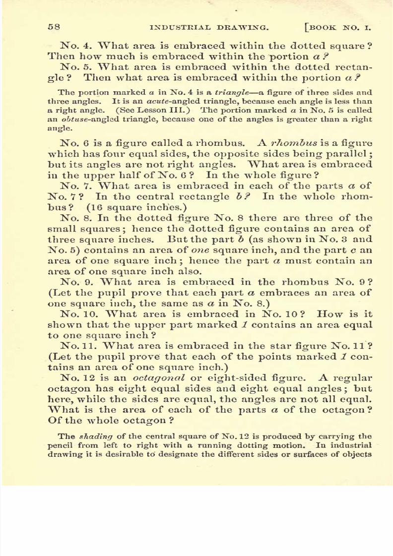
8/2/2019 Drawing Guide Ma Nu Will Rich
http://slidepdf.com/reader/full/drawing-guide-ma-nu-will-rich 64/236
58 INDUSTRIAL DEAWIXG. [BOOK NO. I.
No. 4. What area is embraced within the dotted square ?
Then how much is embraced within the portion a f
No. 5. What area is embraced within the dotted rectan-
gle ? Then what area is embraced within the portion a ?
The portion marked a in No. 4 is a triangle a figure of three sides and
three angles. It is an acute-angled triangle, because each angle is less than
a right angle. (See Lesson III.) The portion marked a in No. 5 is called
an obtuse-angled triangle, because one of the angles is greater than a right
angle.
No. 6 is afigure
called a rhombus. A rhombus is afigure
which has four equal sides, the opposite sides being parallel ;
but its angles are not right angles. What area is embraced
in the upper half of No. 6 ? In the whole figure ?
No. Y. What area is embraced in each of the parts a of
No. 7 ? In the central rectangle b f In the whole rhom-
bus? (16 square inches.)
No. 8. In the dottedfigure
No. 8 there are three of the
small squares ;hence the dotted figure contains an area of
three square inches. But the part b (as shown in No. 3 and
No. 5) contains an area of one square inch, and the part c an
area of one square inch;hence the part a must contain an
area of one square inch also.
No. 9. What area is embraced in the rhombus No. 9?
(Letthe
pupil provethat each
parta embraces an area of
one square inch, the same as a in No. 8.)
No. 10. What area is embraced in No. 10? How is it
shown that the upper part marked 1 contains an area equal
to one square inch ?
No. 11. What area is embraced in the star figure No. 11 ?
(Let the pupil prove that each of the points marked 1 con-
tains an area of onesquare inch.)
No. 12 is an octagonal or eight-sided figure. A regular
octagon has eight equal sides and eight equal angles; but
here, while the sides are equal, the angles are not all equal.
What is the area of each of the parts a of the octagon ?
Of the whole octagon ?
The shading of the central square of No. 12 is produced by carrying the
pencil from left to right with a running dotting motion. In industrial
drawing it is desirable to designate the different sides or surfaces of objects

8/2/2019 Drawing Guide Ma Nu Will Rich
http://slidepdf.com/reader/full/drawing-guide-ma-nu-will-rich 65/236
STRAIGHT LINES AND PLANE SURFACES. 59
very distinctly by the shading ;and this is one of the kinds of shading
very appropriate for that purpose.
No. 13. What is the area of each of the rhombuses mark-ed a f (See No. 4 and No. 6.) What is the area of the
central star figure ? (See No. 11.) What is the area of the
whole octagon ?
No. 14. What is the area of each of the rhombuses marked
a ? (See No. 9.)Of each of the star points marked b f (See
No. 4.)Of the central square c f Of the whole octagon ?
PROBLEMS FOB PRACTICE.
1. Draw a rectangle similar to the dotted rectangle No. 4. but four times
as large. (See ELEMENTARY PRINCIPLE, page 54.)
2. Draw a triangle similar to a of No. 4, but nine times as large. Howmust the sides compare in length with those of a of No. 4 ? What will
be the area of the triangle ?
3. Draw a triangle similar to a of No. 5, but containing sixteen times the
area of No. 5.
4. Draw a rhombus similar to No. 6, but containing twenty-five times the
area of No. 6. Shade it with two-space diagonals like 6, or c, of No. 1 .
5. Draw a rhombus similar to No. 7, but containing only one fourth the
area of No. 7.
6. Draw a figure similar to the a portion of No. 8, but sixteen times as
large.
7. Draw a rhombus similar to No. 9, but containing twenty-five times the
area of No. 9.
8. Draw a rhombus similar to No. 10, but having four times the area ofNo. 10.
9. Draw a star figure similar to No. 11, but containing nine times the area
of No. 11.
10. Draw an octagon similar to No. 12, but containing four times the area
of No. 12.
11. Draw an octagon similar to No. 13, but containing nine times the area
of No. 13. Divide it as No. 1 3 is divided, and mark within each rhombus,
its area, and mark the area of the star also.
12. Draw a figure similar to No. 14, but sixteen times as large, and mark
within the parts a, 6, and c the area of each.
Let problems similar to the foregoing be drawn on the
blackboard, or selections from them, at the option of the
teacher.
LESSON VII. No. 1 is a two-space diagonal square ;and
No. 2 is the same in a different position. The area of No.1 can easily be counted up, when it is seen that each of the

8/2/2019 Drawing Guide Ma Nu Will Rich
http://slidepdf.com/reader/full/drawing-guide-ma-nu-will-rich 66/236
60 INDUSTRIAL DRAWING. [BOOK NO. I.
parts marked 1 is equal to one square inch. Hence thefig-
ure contains five square inches.
The area of a two-space diagonal square, or of any two-
space diagonal rectangle, may be found by the following
modification of Rule I. :
To find the area of a two-space diagonal rectangle :
RULE B. Multiply the length in two-space diagonals by
the breadth in two-space diagonals, and FIVE times the prod-
uct will be the area, in measures of the primary erect squares.
Thus, in No. 1, multiply the length 1 by the breadth 1, and
5 times the product will be the area: 5 square inches.
What is the area of the two-space diagonal square No. 3 ?
Solution. Multiply the length 2 by the breadth 2, and
the product will be 4, which, multiplied by 5, will give 20
squareinches the area. The same result will be found
bycounting the squares, etc.
What is the area of No. 4 ? No. 5 ? No. 6 ?
No. 7 is the same form of star seen in No. 14 of Lesson
VI.;and No. 8 is the same form that is seen in No. 13. In
drawing these figures, first trace the outlines very lightly;
and do not mark firmly until the positions of all the lines
areclearly
determined. Use no ruler.
No. 9 shows two octagons intersecting each other in a
diagonal direction, and in such a manner that the rhombus
a is common to both. Any octagon may have an octagon
intersecting it in this manner on all of its four divisions;
and when the series is continued they form the pattern
seen in No. 10 sometimes seen in oil-cloths, carpets, etc.
No. 1 1 shows a series ofoctagons intersecting
one another
vertically and horizontally, instead of diagonally as in No.
10. In No. 10 the rhombuses, and in No. 11 the star fig-
ures, are represented as shaded with a light tint ofIndia ink.
PROBLEMS FOR PRACTICE.
1. Draw, on the drawing-paper, a two-space diagonal square, similar to
No. 1, but embracing twenty-five times the area of No. 1. Draw another
within the last, embracing nine times the area of No. 1. What will be the
lengths of the sides of each, in two-space diagonals ? The area of the small-
er square ? Of that portion of the larger square outside of the smaller ?

8/2/2019 Drawing Guide Ma Nu Will Rich
http://slidepdf.com/reader/full/drawing-guide-ma-nu-will-rich 67/236
STRAIGHT LINES AND PLANE SURFACES. 61
2. Draw a rectangle similar to No. 4, but embracing four times the area
of No. 4.
3. Draw a rectangle similar to No. 6, but embracing four times the area
of No. 6.
4. What area would be included in a two-space diagonal rectangle hav-
ing a length of eight two-space diagonal measures, and a breadth of five ?
(See Rule B.)
5. Draw a pattern similar to No. 10, but with the figures embracing four
times the area of those in No. 10.
6. Draw a pattern similar to No. 11, but with the figures embracing four
times the area of those in No. 11.
Free-hand drawing ofproblems similar to the foregoing
on the blackboard.
LESSON YIIL Three-space Diagonals. By a three-space
diagonal is meant the diagonal of a rectangle which is three
times as long as it is broad. Thus, the diagonal of the rect-
angle atcr,No. 1, passes over three spaces, and divides the
rectangle into two equal parts. As the rectangle includesan area of three square inches, each half of it, as marked ^,
has an area of one and a half square inches.
No. 2. What area is included in the dotted rectangle No.
2 ? In each of the three parts, a, b, and c ?
No. 3 is a three -space diagonal square. Observe that
each of the parts marked 1 has an area of one and a half
square inches. Then what is the area of the whole square ?
(Ans. 10 square inches.)
No. 4 is a rhombus. What is its area ? The area of the
dotted rectangle ?
No. 5 is a three -space diagonal rectangle. Its area is
easily found, by counting, to be twenty square inches. But
the area of any three-space diagonal square, or other three-
space diagonal rectangle, however large, may easily be found
by the following rule, also a modification of Rule I.
To find the area of a three-space diagonal rectangle :
RULE C. Multiply the length in three-space diagonals bythe breadth in three-space diagonals, and TEN times the prod-
uct will be the area, in measures of the primary erect squares.
Thus, in the square No. 3, the length 1, of one side, multi-
plied by 1, the length of another side, gives the product

8/2/2019 Drawing Guide Ma Nu Will Rich
http://slidepdf.com/reader/full/drawing-guide-ma-nu-will-rich 68/236
G2 INDUSTRIAL DRAWING. [BOOK NO. I.
1, which, multiplied by 10, gives 10 square inches as the
area.
Apply the rule to No. 5, and test the result by counting.What is the area ?
No. 6. What is the area of the inner dotted rectangle?
Of the large rectangle ? Then what is the area of the space
included between the two ?
"No. 7. The area of the space included within the dotted
figures,,./,2
93 is seen, by counting, to be five square inches.
But the area of the part marked a is one and a half squareinches, and the area of c is the same, the two parts a and c
making three square inches. Therefore the part b embraces
two square inches.
No. 8. What is the area of the rhombus No. 8 ?
No. 9 is a three -space diagonal octagon. What is the
area of each of the parts , #, c, and df Of the inner dotted
square ? Of the whole octagon ?
No. 10. What is the area of the four rhombuses a, #, c, d?
Of the star g ? Of the whole octagon ?
No. 11. What is the area of the four rhombuses a, , c, d?
Of the four parts e, /, g, h ? Of the central square k f Of
the whole octagon ?
No. 12. What is the area of the star in No. 12 ? What is
the area of the star in No. 8 of Lesson VII. ? What is thedifference in their areas ?
Let all the foregoing be drawn on the drawing-paper.
PROBLEMS FOR PRACTICE.
1 . Draw, on the drawing-paper, a three-space diagonal square that shall
contain 9 times the area of No. 3.
2. Draw a rhombus similar to No. 4, but containing nine times the area
of No. 4. Within the rhombus thus
drawn,and
equidistantfrom its
sides,draw a rhombus containing four times the area of No. 4. Within this latter,
and equidistant from its sides, draw another equal to No. 4. Mark the
rhombuses thus drawn No. 1, No. 2, and No. 3, beginning with the smallest,
and mark the area of each.
3. Draw a rectangle similar to No. 5, but containing sixteen times the area
of No. 5. Draw one within this latter containing four times the area ofNo. 5.
4. Draw a rhombus similar to No. 8, but containing four times the area
of No. 8.
5. Draw an octagon similar to No. 9, but containing four times the area
of No. 9.

8/2/2019 Drawing Guide Ma Nu Will Rich
http://slidepdf.com/reader/full/drawing-guide-ma-nu-will-rich 69/236
STRAIGHT LINES AND PLANE SURFACES. 63
6. Draw an octagon similar to No. 10, but with other interlacing octa-
gons on its diagonal sides, similar to No. 10 of Lesson VII.
7. Draw an octagon similar to No. 11, but with other interlacing octa-
gons on its vertical and horizontal sides, similar to No. 11 of Lesson VII.8. Draw a star similar to g of No. 10, but having four times the area of
ff,and inclose it with an interlacing square similar to No. 7 of Lesson VII.
Free-hand drawing ofproblems similar to the foregoing
on the blackboard.
PAGE THREE.
LESSON IX. This lesson consists of a series of net-work,
the finer examples of which, when used in drawing or en-
graving, for the purposes of shading, are called hatching.
No. 1 is a coarse diagonal net-work, in the form of squares.
No. 2 is drawn, in the first place, in the same manner as
No. 1;after which another set of lines is put in, in both
diagonal directions, intermediate between those first drawn.
No. 3 is first drawn the same as No. 2, after which another
set of lines is put in intermediate between those first drawn.
This kind of hatching is seen in No. 6 of the next lesson.
No. 4 is a coarse two-space diagonal net-work.
No. 5 is first drawn the same as No. 4, and is then filled
in with another set of lines between those first drawn.
No. 6 is a fine hatching, first drawn the same as No. 5, and
then filled in with another set of lines intermediate between
those first drawn. A sharp-pointed, hard pencil is required
for this shading.
No. 7 is a coarse three-space diagonal net-work. Whenfilled in with two lines intermediate between those here
drawn, it forms a good hatching for some kinds of shading.
All the examples in this lesson, which should be copied
without the aid of a ruler, will furnish good exercises in
drawing straight, uniform, and equidistant lines. The di-
rections, and the distances apart, are given in the ruling of
the paper.
Free-hand drawing of Lesson IX. on the blackboard.
LESSON X. No. 1 gives the outline of a star-shaped fig-
ure;and No. 2 is the same divided into eight pairs of wings
by a vertical, a horizontal, and two diagonal lines, and then

8/2/2019 Drawing Guide Ma Nu Will Rich
http://slidepdf.com/reader/full/drawing-guide-ma-nu-will-rich 70/236
64 INDUSTRIAL DRAWING. [BOOK NO. T.
shaded. This peculiar star-shaped figure is a common form
of ornament in examples of Byzantine art. What is the
area of each of the eight pairs of wings of No. 2 ? Of thewhole star?
No. 3 is a star similar to No. 2, inclosed in a diagonal
square, but with twice the length of sides of No. 2. How,
then, does its area compare with that of No. 2 ? What is
the area of the diagonal square? (See Rule A, page 56.)
No. 4 is a hexagonal pattern covering the entire surface.
A hexagon is a plane figure of six sides and six angles.When the sides are all equal, and the angles all equal, it is
a regular hexagon. What is the area of one of the hexagonsof No. 4?
No. 5 is a pattern composed of an elongated octagonal
figure and a square, the two forms combined covering the
whole surface. What is the area of one of the octagons ?
Nos. 4 and 5 may be varied so as to embrace a great va-
riety of similar patterns by changing the relative lengths
of the sides. Numerous oil-cloth and carpet patterns are
formed on this basis. Additional variety is given to Nos.
4 and 5 by the bordering, as indicated at a and b. Observe
that the exact distance of the inner lines from the outer
border is given by the intersections of the ruled lines.
No. 6 is an original Moorish pavement pattern, called mo-saic / but it is now common, with various modifications, in
pavements, oil-cloths, etc. It is easily drawn on the ruled
paper. The hatching used in the shading is that of No. 3
of Lesson IX.
No. 7 is an elongated hexagonal link pattern, for borders,
etc. Observe the position of the heavy shaded lines on the
right hand and lower sides.
No. 8 is a double interlacing square. First trace lightly.
PROBLEMS FOR
1. Draw a star similar to No. 2, but nine tittles as lai'ge. What will le
its area ?
2. Draw a star similar to No. 3, but four times as large, and inclose it
with a diagonal square similar to the inclosure of No. 3. Centrally within
each of the corner diagonal squares similar to o, 6, c, d ofNo. 3 place a star
Ufce No, 2 within its qwi] diagqnaj square,'
......
\

8/2/2019 Drawing Guide Ma Nu Will Rich
http://slidepdf.com/reader/full/drawing-guide-ma-nu-will-rich 71/236
STRAIGHT LINES AND PLANE SURFACES. 65
3. Draw a pattern made up of hexagons similar to those of Xo. 4, but of
four times the area, and complete each in a manner similar to a.
4. Draw a pattern like No. 5, but with the exception that the shade;1,
squares shall contain four times the area of those in No. 5. Complete the
several hexagons in a manner similar to b.
5. Draw a pattern composed wholly of figures like No. G. The addition
at a will show how the several figures are to be connected. Shade all like
No. 6j or use different tints of India ink.
G. Draw a link pattern like No. 7, with the exception that each link shall
be two spaces longer than in No. 7, but of the same width.
free-handdrawing of
Lesson
J,and the
problems,on
the blackboard.
LESSON XL No. 1 and No. 2 are the elements of slightly
different patterns formed on the basis of either an erect or
a diagonal square.
No. 3 is the basis of an octagonal pattern. At No. 4 the
short lines
a a a a show the method of marking out anin-
ner octagon whose sides shall be uniformly distant from and
parallel to the sides of the larger octagon ;and No. 5 shows
the figure completed.
No. 6 is the pattern, as carried out, from the preceding
three figures. The central octagons should be shaded with
a light tint of India ink, and the squares with the running
dotsin
horizontallines.
The different kinds of shadingused in the patterns given in these books denote the variety
of colors employed when the pattern is used either in orna-
mental art, or in the designs of oil-cloths, carpets, wall-pa-
per, etc.
No. 7 is a dodecagon a figure of twelve sides and twelve
angles. When the sides are equal, and the angles equal,
the figureis
a regular dodecagon. Whatis
the area ofeach of the parts a, , c, d of this figure ? Of the central
dotted square ? Of the whole dodecagon ?
No. 8 is a dodecagon divided into a border of squares and
triangles, and a central hexagon. What is the area of each
of the two vertical squares ? Of each of the four two-space
diagonal squares? Of each of the six white triangles that
incloses the small darktriangle? Of
the centralhexagon.
9
Of the whole figure ?

8/2/2019 Drawing Guide Ma Nu Will Rich
http://slidepdf.com/reader/full/drawing-guide-ma-nu-will-rich 72/236
66 INDUSTRIAL DRAWING. [BOOK NO. I.
No. 9 is a pattern composed wholly ofintersecting dodec-
agons like No. 8. Each figure, it will be seen, forms a por-
tion .of six other like figures surrounding it. This combina-tion of dodecagons is an original pavement pattern takenfrom a Roman church in the Byzantine period of Roman
history. It is an admirable specimen of geometrical mosaicwork so common in that period; and it must have beenformed upon lines drawn precisely like those given on our
ruled paper; for in no other manner could a series of such
figures be drawn with accuracy.
PROBLEMS FOR PRACTICE.
1. Draw a pattern formed of figures like No.l, allowing the figures to
touchvertically and horizontally. Give to these figures the running dot
shading; and shade the intermediate figures formed between them with a
light tint of India ink.
2. Draw a pattern formed of figures like No. 2, and shade the diagonal
cross with a tint of India ink, and the intermediate figures with the runningdot shading. Leave the diagonal squares unshaded.
3. Draw a double interlacing square like No. 8 of Lesson X., and cen-
trally within it draw a figure like No. 8 of Lesson XI.
Patterns similar to No. 6 and No. 9 may be drawn 4, 9, 16, 25, or 3G
times, etc., larger than the figures here given, by increasing the lengths of
the sides 2, 3, 4, 5, or G times, etc., according to the principles explained
on pages 53 and 54.
Free-hand drawing of Lesson XI., and the problems, on
the blackboard.
PAGE FOUR.
For convenience, we now drop the method of groupingthe examples under the head of Lessons, and here designate
them as separate Figures.Fig. 1 represents an ancient Egyptian pattern of a braid-
ed or woven mat on which the king stood. It is formed of
flat strands of only two colors, each strand passing continu-
ously, in a diagonal direction, over two strands of different
colors, and then under two. The portion of a strand pre-
sented at one view is rectangular, and twice as long as it is
broad.All
the linesin this
figure are diagonals, and shouldbe drawn without the aid of a ruler. The shaded strands

8/2/2019 Drawing Guide Ma Nu Will Rich
http://slidepdf.com/reader/full/drawing-guide-ma-nu-will-rich 73/236
STRAIGHT LINES AND PLANE SURFACES. 67
may be gone over, first lightly, with India ink, and then
with pencil.
Fig. 2 is another Egyptian pattern of matting, in onlytwo colors, but presenting a view quite different from Fig. 1.
Here each light strand passes continuously over two dark
strands, and then under three dark strands. The dark
strands may be considered as the icarp, and are arrangedside by side, all running diagonally; and then the light
strands, being the filling, are woven in diagonally, as stated,
at right angles to the warp. Patterns similar to Figs. 1 and2 may be formed of worsted of two colors.
Fig. 3 is the pattern of an Arabian pavement found at
Cairo, formed of black and of white marble, except the diag-
onal squares, which are of red tile. Go over the diagonal
squares once, and the rectangles twice, with a light tint of
India ink. The Arabians imitated the universal practice of
the Komans of covering the floors of their public buildings,mosques, etc., with mosaic patterns arranged on a geomet-rical system.
Fig. 4 is a decorative pattern, in different colors, from an
ancient Egyptian tomb. It is supposed to have suggestedthe meander, or fret, to the Greeks. (See page 6 of draw-
ings.) The ruler may be used in this figure, after first indi-
catingthe lines
with the pencil alone.
Fig. 5 is an ancient Egyptian pattern, in different col-
ors, from the painting on a tomb. In most of these Egyp-tian paintings the colors are as fresh as if put on yesterday.
Fig. 6 is an octagonal pattern forming intermediate fig-
ures of diagonal squares. The ruled lines furnish conven-
ient guides for forming the width of the octagon border.
Figs.7 and 8 are
samples of mosaic patterns based upontwo of the forms of the central eight-pointed star figure, so
common in specimens of Byzantine ornamental art.
Fig. 9 is another modification of the star figure in mosaic,
here inclosed by an interlacing border.
Fig. 10 represents a portion of a mosaic pavement, in dif-
ferent colors, from the ruins of Pompeii. Observe that the
runningdotted
shadingis done
very lightly,and with a
sharp pencil, in Figs. 7, 8, and 9;but much more heavily, and
with a blunt pencil, in a portion of Fig. 10.

8/2/2019 Drawing Guide Ma Nu Will Rich
http://slidepdf.com/reader/full/drawing-guide-ma-nu-will-rich 74/236
68 INDUSTRIAL DRAWING. [BOOK NO. I.
PROBLEMS FOR PRACTICE.
1. Draw a pattern similar to Fig. 1, but with strands of only half thev/idth of those there represented. The rectangles shown will be of only
half the length of those shown in Fig. 1.
2. Draw a pattern similar to Fig. 2, but with strands of only half the
width of those there represented.
3. Draw a pattern similar to Fig. ?>, but make the lines of every figure
contained in it twice the length of those there represented. How, then,
will the area of each of the figures compare with the area of a similar fig-
ure in the copy ?
4. Draw a pattern similar to and arranged like Fig. G, but make the di-
agonal squares one quarter of the area of those there represented, and the
octagons only three spaces in height and three in width. Let the borders
of the figures be only straight lines. Give to the primary diagonal squares
the dotted shading, and leave the octagons unshaded. This will form a
handsome oil-cloth pattern.
5. Draw a pattern similar to Fig. 7, and of the same proportions, but
containing an area 4 times that of the copy.
6. Draw a pattern similar to Fig. 8, and of the same proportions, but con-
taining an area 4 times that of the copy.
7. Draw Fig. 9, extended upward, but make dark diagonal and smaller
squares in place of the dark erect- squares now shown;then draw the same
pattern on the right, and also on the left, touching at the extreme angles,
so as thus to cover the whole paper with a harmonious pattern.
Free-hand drawing of thefigures ofpage 4, and of all the
problems exceptthe
1th, onthe
blackboard.
PAGE FIVE.
Figs. 11, 12, 13, and 14 are plain border patterns; 11 and
12 being forms of the Grecian /;<#, to be noticed hereafter.
Figs. 15, 16, 17, 18, 19, and 20 are representations of flat
braid of 3, 4, 5, 7, 9, and 1 1 strands. In Fig. 1 6 the next move-
ment is to turn the a strand upward, break it down on the
dotted line 1 2, and pass it over 1) and under c. Then break
the strand d downward on the line 34-,
and pass it under a,
and so on continuously.
In Fig. 17 the movement is continuously from the out-
side, over one and under one / in Fig. 18, over one and under
two, beginning on the left;in Fig. 19, beginning on the left,
over one, under two, and over one; in Fig. 20, beginning onthe left, over one, under two, and over two.
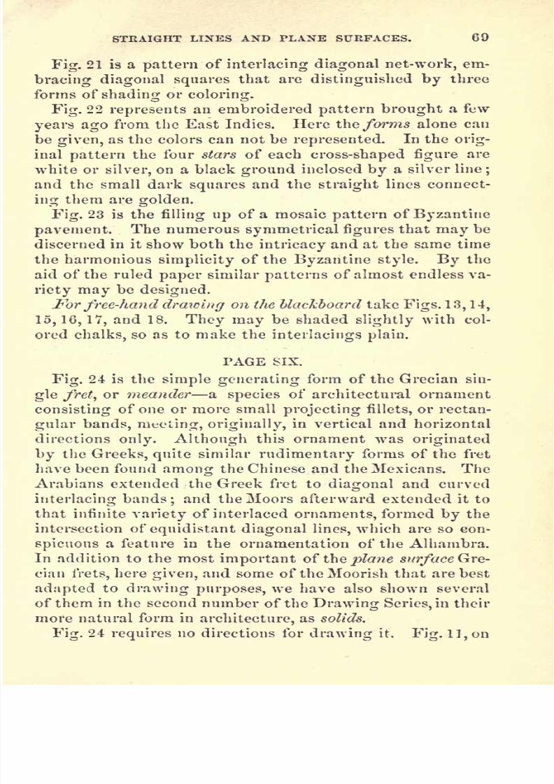
8/2/2019 Drawing Guide Ma Nu Will Rich
http://slidepdf.com/reader/full/drawing-guide-ma-nu-will-rich 75/236
STEAIGHT LINES AND PLANE SURFACES. 69
Fig. 21 is a pattern of interlacing diagonal net-work, em-
bracing diagonal squares that are distinguished by three
forms of shading or coloring.
Fig. 22 represents an embroidered pattern brought a few
years ago from the East Indies. Here \\\Q forms alone can
be given, as the colors can not be represented. In the orig-
inal pattern the four stars of each cross-shaped figure are
white or silver, on a black ground inclosed by a silver line;
and the small dark squares and the straight lines connect-
ing them are golden.
Fig. 23 is the filling up of a mosaic pattern of Byzantine
pavement. The numerous symmetrical figures that may be
discerned in it show both the intricacy and at the same time
the harmonious simplicity of the Byzantine style. By the
aid of the ruled paper similar patterns of almost endless va-
riety may be designed.
For free-hand drawing on the blackboard take Figs. 13, 14,
15,16,17, and 18. They may be shaded slightly with col-
ored chalks, so as to make the interlacings plain.
PAGE SIX.
Fig. 24 is the simple generating form of the Grecian sin-
gle fret, or meander a species of architectural ornament
consisting of one or more small projecting fillets, or rectan-
gular bands, meeting, originally, in vertical and horizontal
directions only. Although this ornament was originated
by the Greeks, quite similar rudimentary forms of the fret
have been found among the Chinese and the Mexicans. The
Arabians extended the Greek fret to diagonal and curved
interlacing bands; and the Moors afterward extended it to
that infinite variety of interlaced ornaments, formed by the
intersection of equidistant diagonal lines, which are so con-
spicuous a feature in the ornamentation of the Alhambra.
In addition to the most important of ihz plane surface Gre-
cian frets, here given, and some of the Moorish that are best
adapted to drawing purposes, we have also shown several
of them in the second number of the Drawing Series, in their
more natural form in architecture, as solids.
Fig. 24 requires no directions for drawing it. Fig. 11, on

8/2/2019 Drawing Guide Ma Nu Will Rich
http://slidepdf.com/reader/full/drawing-guide-ma-nu-will-rich 76/236

8/2/2019 Drawing Guide Ma Nu Will Rich
http://slidepdf.com/reader/full/drawing-guide-ma-nu-will-rich 77/236
STRAIGHT LINES AND PLANE SURFACES. 71
been found in the ruins of Pompeii. The two bands com-
posing the fret, which are here differently shaded, were.of
whitemarble,
formed of the same number ofsquare pieces
as is designated by the ruling of the paper ;and the inter-
mediate spaces, here left unshaded, were of black marble.
Fig. 32 is an interlacing double fret with panels.
Fig. 33 is a double fret with panels, but is not interlacing.
Take away the panels, and the frets are doubly backed uponone another.
Fig.
34 is aninterlacing
doublefret,
formed of distinct
portions connected by a rectangular link.
Fig. 35 is a diagonal and horizontal interlacing double
fret; and, as its form shows, is not Grecian. It is of Moor-
ish origin, and is one of the numerous kinds of complicated
frets, painted in various colors, and on variously colored
grounds, on panels of the walls of temples.
Fig.36 is an
interlacingdouble
fret,
also of Moorish ori-
gin.
Forfree-hand blackboard exercises take Figs. 28, 29, 34, and
36. They may be shaded lightly.
PAGE SEVEN.
Figs. 37 and 38 are borders of fret -work, formed after
Moorish and Arabianpatterns.
Fig. 39 is an Arabian pattern of a mosaic pavement, with
some of the smaller subdivisions omitted. The peculiarstar-form of ornamentation here shown, which is of Byzan-tine origin, was also used by the Arabians.
Fig. 40 is a diagonal double fret, which has been slightly
varied from an Arabian pattern to fit it to our purpose. In
copying it,
either one of the bands should first belightly
traced throughout.
Fig. 41 consists of two four-pointed stars interlacing, so as
to show an eight-rayed or eight-pointed star. In drawing
it, first take the centre, c, then the four inner vertical and
horizontal points marked 3, then the four inner diagonal
points marked 2. Also take the eight ray points in a sim-
ilar manner. Trace lines
very faintlyfrom the outer to the
inner points; then trace an inner set of lines equidistant

8/2/2019 Drawing Guide Ma Nu Will Rich
http://slidepdf.com/reader/full/drawing-guide-ma-nu-will-rich 78/236
72 INDUSTRIAL DRAWING. [BOOK NO. I.
from these; after which mark firmly every alternate ray
border across the other border lines, when, the intersections
being distinct, the whole can easily be finished. The rays
may be made either longer or shorter than those in the
drawing, it being considered that two diagonal spaces are
nearly equal to three vertical or horizontal spaces.
Fig. 42 is copied from an Arabian pattern of a mosaic
pavement in three colors;white (or cream-colored), red, and
black. The groundwork may be said to consist of elon-
gated hexagons connected by interlacing diagonal squares ;
then there is a central interlacing fret ingeniously varied to
adapt it to the other portions, so as to make a perfectly har-
monious meander. In drawing it,first trace the three parts
lightly in the order here described.
Fig. 43 is also copied from an Arabian mosaic, in white,
red, and black. It is taken from a pavement in Cairo. It
will be seen that the diagonal lines here are all two-space
diagonals; and as the drawing conforms strictly to the orig-
inal, it must be true that the original pattern was formed
by the aid of precisely such horizontal and vertical lines as
we have used for guides on the ruled paper.
Observe how beautifully the nine small figures, in three
colors, and three diiferent forms, fill out the six -pointed
star-shapedfigure at the intersection of the several bands.
The entire pattern is a fine example illustrating the fund-
amental principles of decoration;that all ornament should
be based upon a geometrical construction, and that every
pattern should possess fitness, proportion, and harmony, the
result of all which will be a feeling of satisfied repose, with
which every such decoration will impress the beholder,
leaving nothing
further to be desired within the scope of
the ornamentation.
For free-hand blackboard exercises take Figs. 37, 38, and
41. Observe the heavy shading on those sides that would
be in shade if the light came in the direction indicated bythe arrow.

8/2/2019 Drawing Guide Ma Nu Will Rich
http://slidepdf.com/reader/full/drawing-guide-ma-nu-will-rich 79/236
CURVED LINES AND PLANE SURFACES. 73
III. CURVED LINES AND PLANE SURFACES.
PAGE EIGHT.
A curved line is one which is continually changing its di-
rection. If the curve be uniform, it forms part of the cir-
cumference of a circle.
A circle is a plane bounded by a single curved line called
its circumference, every part of which is equally distant
from a point within it called the centre. The circumference
itself is usually called a circle. A straight line drawn from
the centre to any part of the circumference is called a ra-
dius.
Fig. I. At A are six uniform curves of five spaces' span
(five inches), and a depth of one space ;and at Fig. 1 this curve
forms part of a perfect circle. At a and b the directions
of the curves are changed ; but all combined form a harmo-
nious and equally balanced figure, because the additions a
and b are uniform in position and curvature. These figures
should be drawn with the compasses, using the pencil to
make the connections of the curves uniform. Let the pupil
find the centres from which the curves a and b are struck.
Fig. 2 is formed of the same pattern curve used in differ-
ent positions, but all combined to form a harmonious figure.
If either of the half curves, c or d, were omitted, or changedin position, the harmony of the figure would be destroyed.
At Yihe same form of curve is used. Let the pupil find the
centres from which the curves are struck.
Fig. 3 is also a harmonious figure, described wholly by the
compasses ;but the inner border lines from e to h and from
g to f are described with a less radius than that used for
the other curves. The curves e i and g % are, each, only half
of the pattern curve, and are described from the points 1
and 2.
Fig. 4. At _Z? is another pattern curve representing a spanof six inches and a depth of one inch, described from the
centre c, with a radius of five inches. In the shaded four-
angled figure the pattern curve is used in four different po-
D

8/2/2019 Drawing Guide Ma Nu Will Rich
http://slidepdf.com/reader/full/drawing-guide-ma-nu-will-rich 80/236
74 INDUSTRIAL DRAWING. [BOOK NO. I.
sitions. The centres from which these curves are described
are easily obtained on the ruled paper.
Fig.
5 is formedwholly
of combinations of the
patterncurve .Z?, with two half curves at the base, which, however,
are not described from the same centres as the curves with
which they unite.
Fig. 6 is also formed of combinations of the pattern curve
JB. Remembering that all these curves are described with
a radius of five spaces (or five inches), it will be easy for the
pupil
to find their centres.
Fig. 7. We have here, at(7,
a new pattern curve, of a span
of three spaces, and a radius of one space and a half. This
curve forms more than a quarter of the circumference of a
circle, as may be seen in the completed circle at b.
Fig. 8 is formed by very simple combinations of the en-
tire pattern curve C.
Fig.
9 is formed
by adding,
in Fig. 8,
portions
of the pat-
tern curve to the upper and lower extremities.
From the foregoing figures it will be seen that we maytake different portions of any one regular curve, and com-
bine them in a great variety of harmonious patterns. It is
only to a very limited extent, however, that we can combine
uniform curves of different radii in the same pattern, with-
out
destroying
that gracefulness of form which is required
to please the eye, and give to the mind a feeling of repose
in the contemplation.
We now come to the consideration of irregular curves,
such as can not be drawn, to any great extent, by the aid of
compasses.
Fig. 10. We have here a bell-shaped figure, drawn uni-
formly on both sides of the central and balancing line a b.
We must draw one side by the eye alone, and give to the
waving line as graceful a curvature as we can;and a great
many different forms and proportions will answer the re-
quirements of graceful curvature ; but the line must, never-
theless, be such as will please a cultivated eye. Having,
therefore, the point x and the central line a b, we connect a
and x by a curved line that pleases the eye. If, now, we
can draw a line exactly like it on the other side of a #, we

8/2/2019 Drawing Guide Ma Nu Will Rich
http://slidepdf.com/reader/full/drawing-guide-ma-nu-will-rich 81/236
CURVED LINES AND PLANE SURFACES. <"5
shall have a figure of harmonious form, whether a a; be the
most graceful line, by itself, that could be drawn, or not.
But if a x should be drawn of the most graceful form pos-
sible, and a y just as graceful in itself, but differing from u
x, the combination of the two graceful forms would be dis-
cordant, and make an inharmonious figure, because wanting
in symmetry of parts.
Having, therefore, a x, we designate in it any number of
points in which it crosses either the horizontal or vertical
lines of the paper. Let 1, 2, 3, 4, and 5 be these points.
Then dot, lightly, the corresponding points 1, 2, 3, 4, 5 on the
other side of a b, and through them trace the curve, at first
lightly, and afterward fill it out to correspond with the line
a x. The figure is thus made perfectly symmetrical. The
top of the figure may be either pointed or circular;and the
bell may be longer, or narrower, or broader, or any one out
of a great variety of suitable proportions ; yet if the two
sides are alike, the figure will not be unpleasant to the eye.
The two inner dotted curves give different proportions for
the bell, while the base remains the same.
Fig. 11 represents the harmonious outlines of a leaf form.
Observe that the border lines of the leaf pass through the
points 1, 2, <?, 4, 5, on each side of the central line c d, cor-
responding to one other. Thus the points 1 are, each, one
space from the central line; the points , each two spaces ;
the points 3, each three spaces, etc. la this manner the two
sides of the leaf are made perfectly symmetrical. The radi-
ations of the veins from the midrib of the leaf are also sym-metrical.
Fig. 12 is another form of leaf, and although very differ-
ent from Fig. 11 is equally harmonious in proportions. The
pupU should now have no difficulty in copying it accurately
on the ruled paper.
Fig. 13. Here is a group of eight uniform leaves, uniform-
ly radiating from a common centre. The four points a,c,
, (7, are, each, four spaces from the centre, and on lines at
right angles with one another. Hence these four points are
symmetrically arranged. The other four points, , d, /, A,
are in the diagonals, which are intermediate between the

8/2/2019 Drawing Guide Ma Nu Will Rich
http://slidepdf.com/reader/full/drawing-guide-ma-nu-will-rich 82/236
76 INDUSTRIAL DRAWING. [BOOK NO. I.
other lines, and are, each, at the distance of three diagonals
from the centre, a trifle greater than the distance of the
other four points, but sufficiently accurate to give the figureall the symmetry required. Then each leaf must be drawn
by hand. At D the method of beginning the drawing is
shown;atE it is carried still farther forward
;and in Fig.
13 it is completed.
PROBLEMS FOR PRACTICE.
1. Draw Fig. 1, and draw within it a curved line one space distant from
the outer border line.
2. Draw Fig. 2 in the same manner.
3. Draw Y with an outer border line one space distant from the inner
border line, and tint the space between the two.
4. Draw Fig. 3 inverted, with the upper part downward.
5. Draw the upper part of Fig. 5 on each of the four sides of the square
H, so that it shall project in four directions from the central square.
6. Draw Fig. 10 of the same length as at present, but with a base, x y, of
ten spaces.
7. Draw Fig. 11 eight spaces broad at 3 3.
8. Draw Fig. 12 four spaces broader than in the book, and give to the fig-
ure a graceful curve throughout.
Blackboard Exercises. Figs. 1 to 9 inclusive. For these
a pair of chalk-crayon compasses will be needed. See di-
rections, page 49.
PAGE NINE.
Fig. 14. The circle here drawn from the centre c has
longitudinal divisions, by pure curves drawn from different-
points on the central vertical line.
Fig. 15. The irregular curve on the left of the central line
a b had first to be drawn by the eye the design being to
forma
graceful, well-proportioned curve.Its
counterpart,on the other side of the line, is to be drawn in the manner
directed for drawing the preceding figures, 10, 11, and 12.
Fig. 16 is Fig. 15 completed in outline; the two portions
on each side of the central line a b being made symmetrical.
Fig. 17, the completed form, is a portion of a Pompeianborder ornament, painted in yellow on a black ground. The
centralfigure
is
proportioned symmetricallyalso. The
whole is, doubtless, of Greek origin.

8/2/2019 Drawing Guide Ma Nu Will Rich
http://slidepdf.com/reader/full/drawing-guide-ma-nu-will-rich 83/236
CURVED LINES AXD PLANE SURFACES. 77
Figs. 18 and 19 are symmetrically formed leaves, the
drawing ofwhich now requires no farther explanation. Ob-
serve how perfectly the one side corresponds to the other,
and how easy it is to draw such forms on the ruled paper.
Fig. 20, a common form of Grecian conventional leaf or-
namentation, is arranged symmetrically on each side of a
vertical central line.
Fig. 21, a conventional leaf form of ornamentation, can
now be easily drawn.
Fig. 22, also a leaf form, is (or should be) equally bal-
anced on each side of the line a b. Observe that the points
c and d are at equal distances, horizontally, from the line a
by so also the points e and/*, and g and h ; and each leaf di-
vision on one side must have a corresponding division on
the other side.
Fig. 23, a Grecian pattern, shows one of the many forms
of conventional leafage found on Grecian vases. The leaf
forms which the Greeks (and all the ancients) used in their
ornamentation were far removed from any natural types;
and while they are constructed on the general principles
which reign in all plants, they never attempt to represent
any particular species. The moderns, departing from the
true principles of ornamentation which prevail in ancient
art, attempt to give representations of real leaves, flowers,
etc., being even guilty of the anomaly of sculpturing the
most delicate flowers in stone !
Observe that the two portions of each pattern figure are
arranged, symmetrically, on each side of a central line (as a
o), which equally divides not only the inclosing border, but
the symmetrical group of leaves also. Therefore one half of
each group is first to be drawn, and then the other half is to
be made to correspond to it, as shown in preceding figures.
The pupils should trace the leaf forms very lightly at first.
Fig. 24 is the form of a Grecian ornament, painted in goldon a blue ground, on a sunken panel of the ceiling of a Gre-
cian temple. Here, also, it will be observed, the leafage is
purely conventional in form, and not designed to represent
any particular group in nature.
The pattern is arranged symmetrically around the centre c,

8/2/2019 Drawing Guide Ma Nu Will Rich
http://slidepdf.com/reader/full/drawing-guide-ma-nu-will-rich 84/236
78 INDUSTRIAL DRAWING. [BOOK NO. I.
the diagonal leablades dividing it into four equal portions.
Taking the upper quarter section, observe that the points
of the leaves b b are equidistant from the central line ; the
slender volutes bend over equally in graceful curves, and
the radiating leafage below them fills the figure with grace-
ful forms symmetrically disposed. Having the ruled paper,
the pattern can be accurately drawn withoutdifficulty.
PROBLEMS FOB PRACTICE.
After the
pupil
hascopied
the
exampleson
page 9,
let him draw the fol-
lowing :
1 . Draw a figure similar to Fig. 1 7, but two spaces higher, and two spaces
naiTOwer.
2. Draw Figs. 18 and 19, each four spaces longer, and of the same width,
in the widest parts, as in the book.
3. Draw Fig. 21, symmetrically, on a smaller scale.
4. Let the pupil design a figure similar to Fig. 22, but of different propor-
tions.
5. Let the pupil draw the pattern figures in Fig. 23, each two spaces high-
er, but of the same width as at present.
Blackboard Iticercises.Figs. 16, 18, 19, 20, 21, and 22.
PAGE TEN.
All the patterns on this page are plain examples of what
is called Renaissance ornament; by which is understood
the style of ornamentation which sprung up in Italy uponthe revival of art after the Dark Ages. (See page 41.). The
examples here given are from beautiful colored specimens
of glazed pottery of the sixteenth century.
Fig. 25. In copying this pattern the outlines should first
be drawn lightly, as shown at A. First draw a single-line
outline of all the figures in the pattern, making each figure
symmetrical on each side of its central line; then finish thetwo-line border of each figure. The minor divisions of each
figure can then easily be drawn.
Fig. 26. The outlines of this figure are to be drawn bythe compasses, as shown at B. Thus, the points a are the
centres of the semicircles which make up the general outline
of the pattern.
Fig. 27. In this pattern the outer semicircle of each fig-
ure is drawn from the centre a, with a radius of five spaces ;

8/2/2019 Drawing Guide Ma Nu Will Rich
http://slidepdf.com/reader/full/drawing-guide-ma-nu-will-rich 85/236
CURVED LINES AND PLANE SURFACES. 79
and the inner and smaller carves are described from the
points b, cy d, etc.
Fig.28. While the lower
portionof this bulb
patternis to
be drawn with the compasses, they can afford no aid in
drawing the upper portion. The outlines of the central
row of bulbs are first to be drawn of uniform curves on
both sides, for which the ruling will be a perfect guide.
PROBLEMS FOR PRACTICE.
1 . Draw and shade Fig. 25 in full, after the enlarged outline form shown
atZ>.
2. Draw and shade Fig. 26, according to the enlarged outline form shown
at (7, which is four times the size of the pattern. Why is it four times the
size?
3. Draw an outline ofone of the series in Fig. 27, four times its present size.
4. Draw Fig. 28 lengthwise of the paper, and four times its present size.
Blackboard Exercises. The bulb-pattern Fig., and Fig.
25, enlargedas at
D.
PAGE ELEVEN.
Fig. 29 is a Grecian pattern of a painting on vases. It is
still another example of conventional flower representation,
in which only the general principle of the pendulous flower-
bud is retained. It is drawn with the greatest regard to
symmetry.The
right-hand portion,left
partly unshaded,shows how the forms of the pendulous buds are drawn sym-
metrically, and of uniform size.
Fig. 30 is a Byzantine interlaced circular pattern, sculp-
tured in stone, from Milan, Italy. It is very easily drawn,
almost wholly by the compasses. Trace the whole very
lightly at first. The light is supposed to come diagonally
fromabove,
from the
right
hand.
Fig. 31 is a copy of one of the Assyrian painted ornaments
found among the ruins of Nineveh. The central circles, a
(see the end marked -S), were black;the inclosing ring, b
y
dark reddish brown;the winding band, c, orange ;
and the
other winding band, d, blue;while the spaces within the
borders, outside of the winding bands, had a groundwork
of reddish brown. The blue winding band wasseparatedfrom the orange, wherever they were contiguous, by a black

8/2/2019 Drawing Guide Ma Nu Will Rich
http://slidepdf.com/reader/full/drawing-guide-ma-nu-will-rich 86/236
80 INDUSTRIAL DKAWIXG. [BOOK NO. L
line. Thus the ancient Assyrians understood the now ad-
mitted principle that one color should never impinge upon
another, and that all contiguous colors should be separated,
generally by either white or black lines. The entire pattern
may be easily and accurately drawn by the compasses.
The same pattern is also found differently lined and colored,
somewhat as shown at the end marked C.
Fig. 32 is a Byzantine pattern of interlaced ornament, to
be drawn wholly by the compasses. The central points
from which the several circles and semicircles are describedcan easily be found by the pupil.
Fig. 33 is a partially completed pattern, showing the meth-
od of putting in a series of uniform divisions that radiate
from the centre of a circle. The circle is easily divided into
eight equal parts by lines radiating from the centre on the
vertical, horizontal, and diagonal lines, as indicated by the
lettering. Each eighth of the circumference is then to bedivided into three equal parts by the compasses, and the
opposite points in the circumference are connected by slight-
ly traced or dotted lines passing through the centre. The
bases of the radiating white stars can then be designated
with sufficient accuracy by the eye, as the points to which
the sides of the stars are to be drawn, on the second circle,
are intermediate between the radiating dotted lines. Fig-ures similar to this are numerous in ancient ornamental art.
Fig. 34 is a Byzantine pattern of interlacing circles.
Though seemingly intricate, it is quite easily drawn, and
wholly by the compasses. It would, however, be impossi-
ble to draw it with any approach to accuracy without the
aid of the ruled paper ;and there can be no doubt that it
was originally drawn onaground prepared with
linessuch
as those we have given. The ruling gives the exact centre
of every circle, and renders all measuring unnecessary. Ob-
serve that the heavy shadows indicate that the light comes
from above, and from the left. The background may be
shaded with a uniform tint of India ink, or by the pencil,
as indicated in the upper left-hand portion.
Fig.35 is also a
Byzantineinterlaced
ornament,a consid-
erable portion of which may be drawn by the compasses.

8/2/2019 Drawing Guide Ma Nu Will Rich
http://slidepdf.com/reader/full/drawing-guide-ma-nu-will-rich 87/236
CURVED LINES AND PLANE SUEFACES. 81
Thus the three circular bands, and the projections of the in-
terlacing loops as described from, the vertical, horizontal,
and diagonal centres a, a, a, etc., are all easily and accurate-
ly drawn. The connecting and interlacing of the loops cen-
trally must be done by hand, guided by the eye alone;but
after having drawn one of the connections, as from b to d,
the others may be drawn in symmetrical conformity to it.
Observe how the shadows are cast, the light coming diag-
onally from the left, and from above.
PROBLEMS FOR PRACTICE.1. Draw a pattern similar to Fig. 29, but let the semicircular black line,
from the end of which the flower-bud is suspended, be drawn with a radius
offour spaces, instead of three;and let the flower-bud be two spaces longer
and one space broader at the broadest part.
2. Draw a pattern similar to Fig. 31, but describe the larger circles with
a radius one space greater than in the figure.
3. Draw a pattern similar to Fig. 33, but describe the outer circle with
a radius of eight spaces, and divide each eighth part of the circumferenceinto four equal parts, instead of three, thus giving to each eighth part one
ray more than in the figure.
4. Draw Fig. 34 on a larger scale, having the radius of the larger circles
six spaces, instead of five.
5. Draw Fig. 35 on a larger scale, at the option of the pupil.
Blackboard Exercise. So much of Fig. 35 as there is
room for on the board. It would require a board four feet
square to draw it in accordance with the enlarged ruling
of the board. .#
PAGE TWELVE.
We have given on this page a number of original designs,
for the purpose of indicating the facility with which an im-
mense variety of very pleasing patterns may be drawn al-
most wholly by the compasses alone.
Fig. 36 is an ornamental figure called a quarterfoil, in-
closed within a circle. The quarterfoil, often used in archi-
tecture, is disposed in four segments of circles, and is a con-
ventional representation of an expanded flower of four pe-
tals. The lettering shows with what ease and accuracy it
is drawn on the ruled paper.
Fig. 37 is an ornamental figure consisting of eight e'D2

8/2/2019 Drawing Guide Ma Nu Will Rich
http://slidepdf.com/reader/full/drawing-guide-ma-nu-will-rich 88/236
82 INDUSTRIAL DRAWING. [BOOK NO. I.
ments of circles, described from the eight numbered points
which are at the extremities of the dotted vertical, horizon-
tal^
anddiagonal
lines. After
drawingthese dotted
lines^,of indefinite extent, but all passing through the centre c,
equidistant points in all of them, for describing the seg-
ments, may be found by cutting the lines with the circum-
ference of a circle described from the centre c. From the
points ./, #, 3, 4> etc., the segments are described with a
length of radius that will barely allow the inner segments
of circles to touch one another.
Fig. 38. The segments of circles are here drawn in a
manner similar to those shown in Fig. 37; and then these
segments are connected by ribs passing through the centre.
The intervening spaces are then shaded, so as to give the
filling -up a raised and rounded appearance, the heaviest
shades being found on the lower right-hand portions the
light being indicated
by
the arrow A. as
coming diagonallyfrom the left hand, and from above. The spaces covered
by the heavy dark shade on the outside borders of thefig-
ure the heaviest at the right and below are marked out
accurately by the compasses, by moving the fi^ed point of
the compasses uniform distances, diagonally, from the cen-
tres 1 to the points 2. By looking at the figure through a
tubular opening, it will seem to stand out from the
paper
as
if embossed upon it inrelief.
Fig. 39 is similar in its border outlines to Fig. 38; and
all of it, with the exception of the central portion, may be
easily and accurately drawn, and mostly shaded, by the
compasses alone. To draw the central figure accurately,
first trace out lightly, in the space which it covers, the ver-
tical, horizontal, and diagonal lines, after which the raised
wedge-shaped oval figures may be drawn in between
these lines by hand. Observe how the heavy shadows are
formed^
Fig. 40, drawn on the same general plan as the precedingtwo figures, requires no additional explanation. The shaded
cross-ribs are easily drawn after making the raised circles
of uniform size around their given central points. As theset~" 1
r>oints are determined by the tint lines on the draw-

8/2/2019 Drawing Guide Ma Nu Will Rich
http://slidepdf.com/reader/full/drawing-guide-ma-nu-will-rich 89/236
CURVED LINES AND PLANE SURFACES. 83
ing-paper, the whole figure may be drawn with the greatest
ease and accuracy.
Fig. 41 is a pattern of seeming intricacy, but very easily
drawn, and planned on the same general principles as the
preceding figures on the same page. Every thing is drawn
by the compasses from points indicated by the ruling of the
paper, except the raised wedge-shaped ovals, that look as if
embossed.
Fig. 42 is an interlaced pattern, drawn wholly by the com-
passes, with the exception of the central figure. The figures
./, , #, 4, etc., show the eight central points from which the
interlacing curves are described.
blackboard Exwcises. Figures 41 and 42, omitting the
central eight-leaf flower patterns.
Page 12 of this book illustrates, very happily, the great
advantage which the ruled paper affords for drawing curvi-
linear patterns. It would be next to an impossibility to
draw these designs with accuracy without this aid; butwith this ruling, this kind of drawing, which is used to a
great extent in all the decorative arts, becomes a very sim-
ple matter, easy of attainment by all who can describe a
circle by the aid of the compasses.

8/2/2019 Drawing Guide Ma Nu Will Rich
http://slidepdf.com/reader/full/drawing-guide-ma-nu-will-rich 90/236
DRAWING-BOOK No. II.
CABINET PERSPECTIVE PLANE SOLIDS.
THE Cabinet Perspective presented in this series is a meth-
od of representing solids, both plane and curvilinear, in
such a manner that the drawings shall give, by the aid of
the ruled paper, the correct measurements of the objects
represented. The ruling on the paper is adapted to any
scale of measurement ; but, for the purposes of the present
illustration, let it be supposed that the vertical and horizon-
tal lines on the paper are respectively one inch apart.
In all drawings in what is called Diagonal Cabinet Per-
spective? objects are supposed to be viewed in a manner
similar to that in which the two cubesf in Fig. 1, on page 1
of Drawing-Book No. II., are represented. Taking the cube
at JB for illustration, this may be supposed to be a cube six
inches square, the front face of which is in a vertical posi-
tion. The spectator is supposed to view this cube from
such a point, above and at the right of the cube, that he
may see just as much of the upper side .of the cube as of the
right-hand side; so that the apparent width, 10 9 of the
upper face, or 12 of the side face, shall measure, in the
directions indicated, one half the width of the front face ;
and so that the diagonal corner lines, 1 2, 3 4-> and 5 6, will
seem to rise diagonally at an angle of forty-five degrees ;
while the distance from which the view is taken is supposed
* There is a beautiful practical application of Cabinet Perspective, called
/Semi-diagonal Cabinet Perspective, which will be found illustrated on pages
9-11 of Drawing-Book No. IV. See page 171.
t A cube is a regular solid body, having six equal square sides.

8/2/2019 Drawing Guide Ma Nu Will Rich
http://slidepdf.com/reader/full/drawing-guide-ma-nu-will-rich 91/236
CABINET PERSPECTIVE PLANE SOLIDS. 85
to be so great that these lines will appear to be, as they are
here drawn, parallel.
The front face of the cube is drawn in its real proportions
as a square, and as though it were seen in a vertical plane
directly fronting the spectator. According to the scale
supposed to be adopted in the ruling, the front of the cube
measures six inches to a side. The farther face of the cube,
being also vertical and parallel with the front face, and
therefore in a plane also directly fronting the spectator,
would also be drawn as a square if it could all be seen, meas-
uring six inches to a side. Hence each of the lines 2 4 and4 6 measure six inches, the same as 1 3 and 3 5.
But each of the diagonal lines 1 2, 3 h and 5 6, being
corner lines of the cube, must also represent a measure of
six inches;and as each of these lines extends over three di-
agonals of the small squares, it follows that what we call
one diagonal space measures twice as much as a vertical or
a horizontal space,whenever this diagonal space is applied to
the measurement of a line representing a horizontal line.
We may, therefore, adopt the following rule for the meas-
urement (and also for the drawing) of all objects in diag-
onal cabinet perspective.
ELEMENTARY RULE.
Drawings of surfaces that are supposed to be in a vertical
plane fronting the spectator are measurable, in any direc-
tion, according to the scale adoptedfor the vertical and hor-
izontal spaces of the ruling; while each DIAGONAL space
fhat measures a line in a horizontal and diagonalposition is
to be taken as TWICE the measure ofa space of the other kind.
Applying this rule to the cube at 2?, Fig. 1, we find that
all the horizontal lines, and also all the vertical lines thatcross the front face of the cube, measure each six inches in
length, because each extends over just six of the ruled
spaces, and all are in a vertical plane fronting the spectator.
For a similar reason each one of the vertical lines on the
right-hand side of the cube, and each one of the horizontal
lines on the top of the cube, measures six inches, because
each may be supposed to be in a plane like that which

8/2/2019 Drawing Guide Ma Nu Will Rich
http://slidepdf.com/reader/full/drawing-guide-ma-nu-will-rich 92/236
86 INDUSTRIAL DRAWING. [BOOK NO. II.
forms the front face of the cube directly fronting the spec-
tator. But such lines as 1 2, 3 4, 5 6, 8 9, 10 11, and 12 IS,
being seen obliquely, can not be in any plane fronting the
spectator; and as they lie in a diagonal direction, and rep-
resent horizontal lines, they are measurable by the prin-
ciple adopted in the latter part of the rule. Hence the line
a b measures five inches;c d four inches
; g 13 four inches;
m n six inches : but 8 9 measures six inches;10 11 nieas-
sures four inches;12 IS measures four inches, etc. The
cube atA measures two inches on each of its corners.
Fig. 2. Applying the scale of measurement which we have
adopted to the representation of the cube at D, Fig. 2, we
find that the front face of the cube is a square of four inches
to a side;and that the diagonal horizontal distance 1 2, or
8 4, or 5 6, also measures four inches. Also, if we draw in-
termediate lines between the ruled lines on the paper, on
the upperface and
right-handface of the
cube,so as to
giveowe-inch diagonal measures, then sixteen one-inch squares
may be counted on each of the three visible faces or sides
of the cube. We thus have, according to the scale of one
inch to a space horizontally or vertically between the lines,
and two inches for a diagonal space, the exact measurement
of the three visible sides of the cube.
To find the contents of a cube:
RULE. Multiply the length of a side of the cube by itself,
and that product again by a side, and this last product will
give the contents required. (See RuleI., page 53, for the
measurement of surfaces.)
Thus, in the cube at D, Fig. 2, if we multiply the length
(1 2)
of one side, which is four inches,
bythe
length (2 4)of another side, which is also four inches, we get the prod-
uct 16, which is the number of solid cubic inches contain-
ed in the upper tier of the cube as may also be seen by
counting them;and as there are four of these tiers, we mul-
tiply the 16 by 4, and get 64, the number of cubic inches in
the four tiers, or in the whole cube. Or, 4 x 4 x 4= 64 cubic
inches.
One cubic inch is represented at C, which, according to

8/2/2019 Drawing Guide Ma Nu Will Rich
http://slidepdf.com/reader/full/drawing-guide-ma-nu-will-rich 93/236

8/2/2019 Drawing Guide Ma Nu Will Rich
http://slidepdf.com/reader/full/drawing-guide-ma-nu-will-rich 94/236
88 INDUSTRIAL DRAWING. [BOOK NO. II.
pipeds, all of the same size;Gr being viewed in a vertical
position,H horizontally, and ^Tand 7 horizontally and diag-
onally. They may be considered pieces of timber, each twoinches square at the ends, and twelve inches long. What
are the solid contents of each? Ans. 48 cubic inches.
Observe that, according to the scale of measurement al-
ready explained, these pieces measure precisely the same in
these three different positions.
Fig. 4. According to the definition of a parallelepiped,
this figure, also,is
one of that kind. What are its meas-urements, and its contents ?
Observe that the right-hand sides of the foregoing figures
are represented as shaded with a deep tint of India ink, the
front with a lighter tint, and the top of Fig. 4 with the run-
ning dotted shading. The kinds of shading used in Fig. 4
are well adapted to all plane solids, as the object of shad-
ing,in cabinet
perspective,is
to render theseveral
surfacesas marked and distinct as possible, one from another.
Fig. 5 is a square frame composed of four pieces, each two
inches square; the two diagonal side-pieces each twelve
inches long, and the other two each eight inches long.
What is the size of the square which they inclose?
Fig. 6. Let the pupil describe Fig. 6 that is, tell how
many pieces composethe
figure,their
size, position,etc.
Fig. 7 is drawn, first, in the same manner as Gr of Fig. 3;
it is then divided so as to represent cubical blocks, each two
inches square, placed one above another. Three of these
blocks are represented as shaded with the hatching de-
Hcribed in Lesson IX. of Drawing- Book No. I., after first
tinting the surface with India ink.
Fig.8 is
composedof two vertical
blocks,each two inches
square and five inches long, resting upon the ends of a piece
one inch by two inches, and twelve inches long; the latter
being viewed diagonally.
Fig. 9 is the same as No. 8 inverted, and still viewed di-
agonally.
Fig. 10 is also the same as Fig. 8;but it is here viewed hori-
zontally.
Thus the samefigure may
berepresented
in several
different positions, so as to bring each side into full view.

8/2/2019 Drawing Guide Ma Nu Will Rich
http://slidepdf.com/reader/full/drawing-guide-ma-nu-will-rich 95/236
CABINET PERSPECTIVE PLANE OLIDS. 89
In these several figures observe the effect of the shading,
which is rapidly executed with different tints of India ink,
exceptthe
upper surfaces,which have the
runningdot-line
shading.
PROBLEMS FOR PRACTICE.
1. Draw the representation of a square frame similar to Fig. />,of the
same outside and inside measure as Fig. 5, but composed of pieces only one
inch thick instead of two inches;and all of them two inches wide.
2. Draw a figure similar to Fig. 6, but let the upper pieces be only one
inch thick (or high), and let them project each one inch at both ends be-
yond the lower pieces.
3. Draw a figure similar to Fig. 7 in position, but four inches wide and
two inches thick the wide side being in front.
4. Draw a figure similar in position to Fig. 8, but composed of three pieces,
each twelve inches long, four inches wide, and one inch thick.
5. Draw Fig. 9 with the side in a plane fronting the spectator.
Free-handBlackboardExercises.Figs.
5 to 10 inclusive
letting a space on the blackboard represent its true meas-
ure, two inches. In this case only one half of a diagonal
measure will be required for a distance of two inches. In
order to render the several surfaces distinct one from an-
other, the dark shades may be represented by heavy ver-
tical chalk lines, and the lighter shades by very light ver-
tical lines. Or, where colored chalk crayons are accessible,
the dark shades may be represented by blue lines.
Fig. 11, in its complete outline, is a cube eight inches
square, having a small cube two inches square cut from
each of its four upper corners. See the form of the entire
cube, as represented by the dotted lines. What were the
contents of the entire cube ? What the contents after the
four corners were taken out.
Fig. 12 is a cube twelve inches square, having a piece eight
inches square and two inches thick taken from the centre of
each of its three visible sides. What were the contents of the
entire cube before the three pieces were taken out ? Whatwere the contents after these pieces were taken out ? Let
the pupil be careful, in drawing the figure, that his measures
shall be correct. Thus, the depth of the recess in each side
must measure two inches. Thus c d and m n are measures

8/2/2019 Drawing Guide Ma Nu Will Rich
http://slidepdf.com/reader/full/drawing-guide-ma-nu-will-rich 96/236
90 INDUSTRIAL DRAWING. [BOOK NO. II.
of two inches each;and a b, being one diagonal, is also a
measure of two inches.
Fig. 13 represents a rectangular frame measuring ten byfourteen inches, and composed of pieces two inches square
framed into posts two inches square and ten inches long.
CrifP' To get the full effect of the figures on this page,
view them from a point at the right, and above them,
through the opening formed by the partially closed hand.
The pupil should be accustomed to view his drawings in
the same manner.
PROBLEMS FOR PRACTICE.
1. Draw a figure similar to Fig. 11, but twelve inches square, having a
block four inches square cut from each of its four upper corners.
What would be the contents of the entire cube? What the contents after
the four comers were taken out?
2. Draw a figure similar to Fig. 12, but fourteen inches square, and show-
inga
rectangular pieceten inches
squareand four inches in thickness cut
from the centre of each of its three visible sides.
What would be the contents of the entire cube? What the contents after
the three rectangular pieces were taken out.
3. Draw a figure similar in all respects to Fig. 13, except that the four
horizontal pieces of the frame-work are to be only one inch in veriicr.l
thickness.
Free-hand Blackboard Exercises. Figs. 11, 12, and 13;
also the accompanying problems.
PAGE TWO. SCALE OF ONE INCH TO A SPACE.
Fig. 14 represents a cube eight inches square; and Fig.
15 represents a box formed of one-inch stuff, open at the top,
and of a size that will just receive the cube; so that the lat-
ter, when placed within the box, shall fill it even with the
top. AtA is the cover that will just fit the top of the box.
What is the size of the cover ? Of the side J3 of the box ?
Of the sides C Cf Of the bottom of the box ? What arc
the outside measures of the box when the cover is on it ?
Fig. 16 represents a series of five blocks placed one upon
another, and rising in the form of stairs. The upright piece
in a stair (as a) is called the riser, and the part on which
the foot is placed (as b) is called the tread In Fig. 16 the
stairs are so placed that the risers front the spectator; but

8/2/2019 Drawing Guide Ma Nu Will Rich
http://slidepdf.com/reader/full/drawing-guide-ma-nu-will-rich 97/236
CABINET PERSPECTIVE PLANE SOLIDS. 91
in Fig. 17 the side of the stairway fronts the spectator, and
the riser is viewed diagonally. Fig. 17 measures the same
as Fig. 16, with the exception that in Fig. 17 the lower blockis omitted.
If these two figures are supposed to be drawn to a scale
of four inches to a space, what will be the height of each
riser, and the width of each tread ? What the width of the
stairway ?
Fig. 18 represents a cabinet frame-work formed of pieces
twoinches
squareat the ends
;
thewhole
framemeasuring
ten* inches by twenty-six. Here the longest side fronts the
spectator; but in Fig. 19 the same frame-work is represent-
ed with the end fronting the spectator. Observe that the
end below c d of Fig. 18, which is there seen diagonally, is
not seen at all in Fig. 19;and that the end below a b of Fig,
19 is not seen at all in Fig. 18. Let the pupil describe tho
severalpieces
of which the frame-work is
composed.Fig. 20 represents a cross made of pieces measuring, at
the ends, two by three inches.
Fig. 21 represents a cabinet square made of one-by-two-
inch stuff, and placed horizontally ; but, as the spectator is
supposed to be above and to the right of it, one of the arms
seems to rise at an angle of forty-five degrees being in the
diagonaldirection of the small ruled
squares.Fig. 22 represents the same cabinet square in a vertical
position, and so placed that the wide side shall front the
spectator. The former, as placed, is a measure for horizon-
tal and diagonal distances;the latter, for horizontal and
vertical distances.
Fig. 23 is an upright frame-work resting on four blocks,
each two inches
square;
having onlytwo of its sides and
the top and bottom inclosed, and containing three shelves
in addition to the top and bottom. Let the pupil describe
this frame-work more fully; and tell (or write out) its meas-
ures in all it's parts distances apart of the shelves, etc. The
whole on the supposition that it is drawn to the scale of
one inch to the space.
The shading on this
page
is
supposed
to be done, first,
with India ink; some of the sides are then shaded with lines

8/2/2019 Drawing Guide Ma Nu Will Rich
http://slidepdf.com/reader/full/drawing-guide-ma-nu-will-rich 98/236
92 INDUSTRIAL DRAWING. [BOOK NO. II.
by the pencil, which, when not too heavy, give additional
life and spirit to the drawing.
PROBLEMS FOR PRACTICE.
As Fig. 14 represents a cube eight inches square, what are its contents in
cubic inches ? A ns. 8x8x8=512 cubic inches.
As it takes 231 cubic inches to make a gallon, how many gallons of water
would the box, Fig. 15, contain ? Ans. 2 gallons and 50 cubic inches.
1. Draw a box, similar to Fig. 15, that would contain a cube twelve inches
square ;and draw the cover separately. How many gallons of water would
such a box contain ?
2. Draw a rectangular box open at the top, the bottom of which shall
measure, on the inside, ten by twelve inches, and let the box be ten inches
deep. How many gallons of water will it contain ?
3. Draw a flight of stairs, similar to Fig. 1 7, to a scale of six inches to
a space, and having the risers twelve inches high, and the tread eighteen
inches wide.
4. Draw a frame similar to Fig. 18, but formed of stuff one by two inches
the one-inch being the height.
Free-hand Blackboard Exercises. Figs. 17, 18, and 20,
and problems 2 and 3.
PAGE THREE. SCALE OF THREE INCHES TO A SPACE.
Fig. 24. At A is represented a piece of timber six bytwelve inches at the end, and four feet long, broadest side
down, having a piece cut from the centre of the upper sideone foot square and three inches deep, to receive crosswise
nnother timber cut in like manner. At B the two pieces
of timber are united at right angles to one another.
The remaining figures on this page are examples of what
carpenters call scarfing, which means the uniting of two
pieces of timber longitudinally by a scarf-joint in common
languageoften called
splicing ; butthe latter term is
moreproperly applied to an overlapping joint that is not notched.
Fig. 25. At C and D are two pieces of timber prepared
for being joined lengthwise by a square scarf-joint. After
placing the timbers in the right position, they are pinned or
bolted together. Let the pupil describe the two pieces.
Fig. 26. At E is the upper piece of timber, and atF the
lower,to be united
bya
scarf-joint,which is formed of the
square scarf-joint combined with the splice-joint. Observe

8/2/2019 Drawing Guide Ma Nu Will Rich
http://slidepdf.com/reader/full/drawing-guide-ma-nu-will-rich 99/236
CABINET PERSPECTIVE PLANE SOLIDS. 93
that the line of union, 2 4, in both E and F, is in the direc-
tion of two-space diagonals ;and as the two lines are of
the same length, and the two timbers lie in the same rela-
tive positions, the cut sections must correspond with one
another. Moreover, E and F are redrawn at G and H;and there it is seen that the diagonal line of union, 2 J^
is in both cases the diagonal of the same rectangle 1 2,
3kFig. 27 shows two pieces of timber, Jand J", prepared for
being joined by the ordinary splice-joint.The two tim-
bers are to be firmly bolted together. But this is by no
means so firm a mode of union as is shown in Figs. 25
and 26.
Fig. 28 shows a still firmer mode of the scarf-joint than
Figs. 25 and 26. Observe that the lines of union inKmeas-
ure precisely the same, and are in precisely the same posi-
tions, as in L. Thus the lines 1 2 and 3 4. are the same in
length and position as the lines 5 6 and 7 8, both being
two-space diagonals.
Fig. 29 shows, perhaps, the firmest of all modes of the
scarf-joint, especially for heavy timbers. JV is the upper
piece; and the two must be united by placingM and Nside by side, and driving them together. Even then, with-
out bolting, they can not be drawn apart lengthwise ; nor, if
the joints be good, can they be easily sprung in any direc-
tion. At Jf the two pieces are shown as they appear when
united.
Fig. 30 represents the same pieces that are shown in Fig.
29;but here drawn in a different position, being placed
sidewise toward the spectator, instead of endwise toward
him as in Fig. 29. Observe that the measures, according to
the scale, are the same in the one case as in the other. That
mode of representation which will give the best view of
the object should in all cases be adopted; and in some
cases both modes should be used, as the one will often give
views of parts that are not shown in the other.
Fig. 31 shows a still different mode of scarfing, and one
that is very firm, and much more easily executed than Fig.
30. When the pieces are firmly bolted together, the inter-

8/2/2019 Drawing Guide Ma Nu Will Rich
http://slidepdf.com/reader/full/drawing-guide-ma-nu-will-rich 100/236
04 INDUSTRIAL DRAWING. [BOOK NO. II.
locking gives them great additional strength against any
force that might tend to wrench them sideways.*
PROBLEMS FOR PRACTICE.
1 . DrawA of Fig. 24 with the narrow side toward the spectator.
2. Draw the two parts of Fig. 25 with the narrow sides toward the spec-
tator.
3. Draw Tig. 28 with the dark sides of both pieces toward the spectator.
4. Design a figure similar to Fig. 30, but of different proportions in the
interlocking parts.
5. What are the contents of
A, Fig.
24;the scale
beingthree inches to a
space ?
6. What are the contents of the entire Figure B ?
Free-hand Blackboard Exercises. Any or all of thefig-
ures on page 3.
PAGE FOUR. SCALE OF TWO INCHES TO A SPACE.
This page shows the different methods adopted by ma-
sons and engineers in laying bricks. A brick of ordinary
size is two inches thick, four inches wide, and eight inches
long. Bricks which are laid lengthwise across the wall,
with their ends toward the face of the wall, are called head-
ers; and those which are laid with their lengths parallel to
the face of the wall, are called stretchers. The two principal
methods of laying bricks in walls, where much strength
is required, are what is called the English bond and the
Flemish bond. In the former, the face of the wall always
shows the headers and stretchers in alternate layers, or
courses, as they are called by bricklayers. Thus at A is a
* It may here be remarked that the only lines in Diagonal Cabinet Per-
spective which are susceptible of direct measurement are the horizontal,
vertical, and diagonal lines;and that when any other line occurs, if it is to
be measured, it must be done by mathematical calculation, after first re-
solving it into the hypothenuse of a right-angled triangle. Thus at G the
lines 2 1 and 1 4 are measurable;the former, according to the scale here
adopted, measures nine inches, and the latter thirty-six inches;and the an-
gle 2 1 4 represents a right angle. Hence the line 2 4 is the hypothenuse
of a right-angled triangle ;and the teacher may show the advanced pupil
how to ascertain its precise length by adding together the squares of the
sides 2 1 and 1 4, nnd then extracting their square root. And so in all
similar cases of the measurement of lines that are neither diagonal, vertical,
nor horizontal.

8/2/2019 Drawing Guide Ma Nu Will Rich
http://slidepdf.com/reader/full/drawing-guide-ma-nu-will-rich 101/236
CABINET PERSPECTIVE PLANE SOLIDS. 95
course of headers, and at B is a course of stretchers ; and
in English bond the face of the wall shows alternate courses
of the two. For Flemish bond, however, the face of each
course is composed of a combination of headers and stretch-
ers. In both, a brick of half the ordinary width, and also
one of half the ordinary length, is often required ;and these
half bricks should be made in every brick-yard.
Fig. 32 represents a wall eight inches thick, laid in En-
glish bond. Observe that the first or upper course is coin-
posed of headers;the second of stretchers
;the third of
headers ;the fourth of stretchers, etc. In drawing these ex-
amples (as in nearly all other cases of drawing), it is neces-
sary to draw the upper portions first that is,to begin at
the top.
Fig. 33 represents a twelve-inch wall in English bond.
Observe that the face of the wall shows alternate courses
of headers and stretchers;while each course is composed
of both kinds, arranged in a peculiar order, as shown in the
drawing.
Fig. 34 represents a sixteen-inch wall in English bond.
The face is the same as in the eight and twelve inch walls.
The upper two courses show the arrangement.
Fig. 35 represents an eight-inch wall in Flemish bond;
showing that each course is composed of both headers and
stretchers.
Fig. 36 represents a twelve-inch wall in Flemish bond.
Here half bricks of both kinds are used.
Fig. 37 represents a sixteen-inch wall in Flemish bond.
Fig. 38 represents what is called English cross bond.
Here the face of the wall shows an arrangement in the sec-
ond stretcher line by which its joints come exactly below
the middle of the bricks in the first stretcher line ; and the
same arrangement of stretchers comes back every fifth line.
By comparing Fig. 38 with Fig. 32 the difference will be
manifest.
Fig. 39 represents a twenty-four-inch wall laid in Flemish
bond, on the farther half of which rises a twelve-inch wall in
English bond, both halves being capped with twelve-by-
twelve-inch stones two inches thick. There are also two

8/2/2019 Drawing Guide Ma Nu Will Rich
http://slidepdf.com/reader/full/drawing-guide-ma-nu-will-rich 102/236
96 INDUSTRIAL DRAWING. [BOOK ]STO. II.
triangular abutments resting on the front half of the lower
wall, and abutting against the upper wall. These abut-
ments are twelve inches high at the back, and their bases
project forward twelve inches, the width of the lower half
of the wall. Their faces, therefore, are laid at an angle of
forty-five degrees ;and hence each layer of stones, of which
the abutment is composed, although only two inches thick,
presents a much greater front surface view. The teacher
may require of the advanced pupil the length of the face of
the abutment, as designated by the line 2 3 or 4 5. SeeNote, page 94.
PROBLEMS FOR PRACTICE.
1. Draw an eight-inch wall in English bond, forty inches in length at the
base, and showing three partial courses and four full courses.
2. Draw a twelve-inch wall in English bond, forty-eight inches in length
at the base, and showing four partial courses and four full courses.
3. Draw a twelve-inch wall in Flemish bond, fifty-six inches in length at
the base, and showing four partial courses and four full courses.
4. Let the pupil design a twenty-inch wall in English bond, and also a
twenty-inch wall in Flemish bond, and so that the bricks will break joint in
the best manner possible.
JBlachboard ^Exercises. Any of the figures of page 4,
showing the true size of the bricks.
PAGE FIVE. SCALE OF TWO INCHES TO A SPACE.
Fig. 40 represents a cross-shaped figure formed by so cut-
ting a cube twenty inches square, that vertical sections,
eight inches square at the ends, are taken away from its
four corners. The form and extent of the entire cube are
shown by the dotted lines. Let the pupil calculate the
number of cubic inches taken away, and the number re-
maining.Fig. 41 represents a cube of the same original size as Fig.
40, from which several sections are cut away, leaving what
is shown in the figure. Let the pupil calculate the number
of cubic inches taken away, and the number remaining.
Fig. 42 shows, on its front vertical face, a single fret of
the same form as is seen at Fig. 24, page 6, of Book No. I.;
but here,in
Fig. 42, thefret is
shown, notas a surface deco-
ration merely, but in the solid form, four inches in thickness.

8/2/2019 Drawing Guide Ma Nu Will Rich
http://slidepdf.com/reader/full/drawing-guide-ma-nu-will-rich 103/236
CABINET PERSPECTIVE PLANE SOLIDS. 97
Observe that the thickness is represented by one diagonal
space.
Fig. 43 shows the same solid fret, but with the addition
of a solid piece four inches square running through it cen-
trally, the two being framed together.
Fig. 44 represents a frame-work thirty-four inches wide
and fifty-sixinches long, the side pieces formed of timbers
six inches square at the ends, and the end pieces formed of
timbers six by sixteen inches at the ends, the end pieces
being mortised into the side pieces by tenons two inches
thick, eight inches wide, and six inches in length. Hencethe mortises which receive the tenons must extend entirely
through the timbers. At A, B^ C, and D, the four timbers
which compose the frame are drawn separately, and in their
relative positions ;and at F they are put together. The
side pieces show mortises for upright posts. At E, one of
the end timbers is represented as standing vertically on one
of its tenons, with its broadest side fronting the spectator.
Observe that, according to the scale, it measures precisely
the same as C or D.
PROBLEMS FOR PRACTICE.
1. Draw the lightly dotted outlines of a cube of the same dimensions as
Fig. 40;and then represent the cube as it would be after taking vertical
sections from its fourcorners,
anl from the centres of its fourbides, each
four inches square at the ends. First mark out, on the upper face of the
dotted cube, the upper face as it would appear after the pieces were taken
out. What would be the solid contents of the eight pieces thus taken out ?
The solid contents remaining in the cube ?
2. Draw a fret similar to Fig. 34, page G, of Book No. L, representing the
solid form of the fret, two inches in thickness;but draw it on an enlarged
plan, so that the width of the fret-line shall occupy a full space. Scale, two
inches to a space.
3. Draw F of Fig. 44 so that the longest side shall front the spectator.
4. Draw the same frame standing on one end, with the broad side front-
ing the spectator.
5. Draw the same frame standing on one end, with the edye of the frame
fronting the spectator.
Blackboard Zeroises. Any of the figures and problemson page 5.
E

8/2/2019 Drawing Guide Ma Nu Will Rich
http://slidepdf.com/reader/full/drawing-guide-ma-nu-will-rich 104/236
98 INDUSTRIAL DKAWING. [BOOK NO. II.
PAGE SIX. SCALE OF TWO INCHES TO A SPACE.
Figs. 45 and 46 represent the same frame-work, but placedin different positions in relation to the spectator ;
and Fig.
47 represents these two frames united by string-pieces, in
the form of a bedstead. Let the pupil give the dimensions,
according to the scale adopted for the page two inches to
a space.
Fig. 48 represents a vertical pillar twelve inches square,
surrounded at the top by a moulding four inches in heightand projecting four inches. Observe that the projection of
the moulding, whether measured horizontally by the dis-
tances 1 2 and 5 6, or diagonally by the distances 2 3 and
4 5, etc., is in all parts four inches. The height of the pillar
is the distance 29, which is twenty inches. Observe the
following rules: 1. A horizontal moulding, or any hori-
zontal projection, conceals from view a portion of the frontvertical surface immediately below
it, equal in height to one
half the projection. Thus the dotted line 7 8 indicates the
lower line of the attachment of the moulding to the front
face of the pillar; by which it is seen that the moulding,fourinches in projection, conceals from view the two inches in
height of the front face of the pillar immediately below the
attachment of the moulding. This principle is also seen in
the fact that the distance from the base of the pillar to the
moulding is measured from 9 to 7 thus making the mould-
ing sixteen inches above the base. 2. A horizontal projec-
tion conceals from view a portion of tJie DIAGONAL vertical
surface immediately beloioit, equal in height to the extent of
the projection.
Thus 8 12 is the line of the attachment of the under sideof the moulding to the side of the pillar; and 12 13 shows
the vertical extent of the side of the pillar which the mould-
ing conceals.
But suppose the front moulding did not project at all
beyond the face of the left-hand side of the column. It will
be seen that, in that case, the front end of the moulding
would terminate in the line S 10; thus having an apparentprojection of two inches beyond the line 7 9, the same as the

8/2/2019 Drawing Guide Ma Nu Will Rich
http://slidepdf.com/reader/full/drawing-guide-ma-nu-will-rich 105/236

8/2/2019 Drawing Guide Ma Nu Will Rich
http://slidepdf.com/reader/full/drawing-guide-ma-nu-will-rich 106/236
100 INDUSTRIAL DRAWING. [BOOK NO. II.
frame, length of its sides, and how joined at the corners;
size of the top of the table, its projection beyond the frame,
thickness and number of the boards which compose it,etc.
Fig. 54 represents a diamond or lozenge-shaped figure
formed of two-space diagonals, and having a thickness of
four inches. What is its length ? Its breadth ? Its front-
face measure in square inches? (See page 58; No7.)
Its
contents in cubic inches ?
Fig. 55 is the same figure as 54, but its length is here
placed in a front vertical position.
PROBLEMS FOR PRACTICE.
1 . Represent a vertical piece of timber twelve inches square at the ends,
and twenty-four inches in height, surrounded by a moulding even with the
top, two inches in height, and projecting four inches; also a like moulding
even with the base of the timber. Be careful to get the correct height of
the timber, as portions of the top and bottom are concealed by the moulding.
2. Make a drawing like Fig. 47, with the exception that the postsshall
rest upon a frame formed of stuff four inches thick and four inches in width,
and that a frame formed of stuff four inches in width and one inch in thick-
ness (or height) shall rest upon the tops of the posts. Be careful to trace
the outlines very lightly at first, and only mark them firmly when the visi-
ble portions are correctly represented.
3. Draw a lozenge whose front face shall be like Fig. 54, but whose diago-
nal length shall be twelve inches.
4. Draw the same lozenge twelve inches in diagonal length, but in the po-
sition of Fig. 55.
Blackboard Exercises. Figures 47, 48, 49, and the fore-
going problems.
PAGE SEVEN. SCALE OF FOUR INCHES TO A SPACE.
All the figures on this page, except Fig. G4, contain some
lines that are neither true diagonals, verticals, nor horizon-
tals; yet their positions are as accurately defined as the
positions of those lines that are directly measurable.
Fig. 56 represents a kind of heavy block table, thirty-two
inches in height, having its top surface thirty-two inches
square, and resting on a base thirty-two inches square. The
base bevels upward, and the top bevels downward to the
same extent. As the line a b is drawn diagonally from the
corner , thirty-two inches, so must the line c d, drawn from
the corresponding cornerc,run diagonally in the same di-

8/2/2019 Drawing Guide Ma Nu Will Rich
http://slidepdf.com/reader/full/drawing-guide-ma-nu-will-rich 107/236
CABINET PERSPECTIYE PLANE SOLIDS. 101
rection;and its real length is thirty-two inches, but the far-
ther eight inches are not visible. It is best to draw the
top first;then the front face
;then the diagonal lines.
Fig. 57 represents the same block table, with the excep-
tion that the vertical section, eight inches in length, is cut
out of the centres of both sides of the base. Observe that
as the distance if is eight inches, so must the distance g a
be eight inches also;and that a b must run toward the point
c, which is a point on the left-hand side of the table corre-
sponding to d. And c and d must be the same distance
apart as n and m.
Fig. 58 is the same as Fig. 57, with the exception that the
section cut out here extends through the entire central sup-
port ;and Fig. 59 shows the same as Fig. 58, with the top
removed.
Figs. 60, 61, 62, and 63 are the same as the figures directly
above them, with their sides turned to the front. Observe
that Fig. 60 measures in all respects, according to the scale,
the same as Fig. 56. Thus the dotted vertical lines in the
base front of Fig. 56, although seen in a side view in Fig.
60, are in the latter, as in the former, the downward con-
tinuation of the columnar support, and in both cases are
eight inches apart, eight inches in length or height, and at
the same distances from the corners a and c. And if the
length of the line a o, in Fig. 60, should be calculated math-
ematically, it would be found to be of the same length as
the same line a o in Fig. 56. Let the pupil trace out the
like measurements in Figs. 61,62, and 63, with the figures
above them.
Fig. 64 represents a heavy frame-work sixteen inches in
height or thickness, and seven feet four inches square, with
a vertical recess of twelve by forty inches in the centre of
each of its four sides, and a vertical opening forty inches
square through the centre of the frame.
Fig. 65 represents the same frame-work as Fig. 64;but in
place of the square opening in the centre, there rises, above
the frame-work in Fig. 65 a four-sided pyramid, forty inches
square at the base, and thirty-six inches in vertical height.
Observe that the outlines of the base of the pyramid are

8/2/2019 Drawing Guide Ma Nu Will Rich
http://slidepdf.com/reader/full/drawing-guide-ma-nu-will-rich 108/236
102 INDUSTRIAL DRAWING. [BOOK NO. II.
the same as the upper surface outlines of the square open-
ing in the centre of Fig. 64, and are represented by: the
same figures, 1, 2, 3, J, in both cases. The centre of the
base of the pyramid, it will be seen, must be the point 9
the point of intersection of the lines 5 6 and 7 8, which
connect the centres of opposite sides of the base. The ver-
tical height of the pyramid above the base must therefore
be the length of the line 9 10, which represents a line drawn
vertically upward from the centre of the base to the apex
of the pyramid.
PROBLEMS FOR PRACTICE.
1. Draw a figure similar to Fig. 56, but forty-four inches square at the
bottom and top ;and with the central vertical support twenty inches high
from o toar,
and only four inches in thickness.
2. Draw the same with the side view brought in front.
3. Draw a figure whose base shall be similar to that of Fig. 65, but whose
extreme side measures from corner to corner shall be six feet, and the
height or thickness eight inches;the recesses on the centres of the sides
sixteen by twenty-four inches;the base of the pyramid twenty-four inches
square, and its vertical height fifty inches.
Blackboard Exercises. Figs. 56, 57, 58, and 62. Also
draw Fig. 65, giving to the frame-work one half the measures
denoted on the paper; but make the pyramid thirty-six
inches in vertical height. The dark shades may be desig-
nated by heavy vertical lines, with either blue or white
crayons.
PAGE EIGHT. SCALE OF ONE FOOT TO A SPACE.
Fig. 66 may be supposed to represent a block of stone
twelve feet square, and four feet in height or thickness.
Suppose that we wish to place, centrally, on the top of this
block a four-sided pyramid, eight feet square at the base,
and fifteen feet in vertical height from the top of the base.
Evidently the base of the pyramid will be, on all sides,
two feet within the outlines of the top of the base on which
it rests. The lines a#, b f, f d, and d a, representing the
outlines of the base of the pyramid, must therefore be drawn
two horizontal spaces within the upper side lines i m and
n j of the base, and one diagonal space within the front
and back lines i n and mj. The centre, c, of the base of

8/2/2019 Drawing Guide Ma Nu Will Rich
http://slidepdf.com/reader/full/drawing-guide-ma-nu-will-rich 109/236
CABINET PERSPECTIVE PLANE SOLIDS. 103
the pyramid, must evidently be at the intersection of the
central lines o p and h g, and these lines will be sufficient
to designate it;but it must also be at the intersection of
the diagonal lines a f and d b of the base. The apex of
the pyramid must be vertical to the point c.
Fig. 67. The top of the base of this figure is the same as
the top of the base drawn in the preceding figure, and on
this base the pyramid, of the same dimensions as that desig-
nated for Fig. 66, is placed. The dotted lines and the let-
ters are put in to designate the same points that are given
in Fig. 66. Observe that the point cc,the apex or vertex of
the pyramid, is taken fifteen spaces vertically above the
centre, c, of the base;and from x lines are drawn to the
corners d, /, and b. The fourth corner-line of the pyramidextends from x to a, but it can not be seen because it is on
the side opposite to the spectator. The line c x is called
the axis of the pyramid.
The base of Fig. 67 is represented as ten feet in height
and twelve feet square ;and it has recesses in the centres of
its sides six feet high, eight feet wide, and two feet in depth.
Fig. 68 is a wedge-shaped pyramid, eight feet square at
the base, and eleven feet in vertical height. Observe how
the edge, a byof the pyramid is drawn so as to be directly
above the central diagonal line, g A, of the base.
Fig. 69 is the same as Fig. 68 ; but the side view of the
wedge is here brought in front of the spectator. Observe
that the measurements are the same in both cases. See the
height, a g, in both.
Fig. 70 has the same base, eight feet square, and the same
height, eleven feet, as the preceding two figures; but the
wedge-shaped pyramid is diminished to four feet at the apex.
If the edge of the pyramid were the line a b, the figure
would be the same as Fig. 68; but the edge is diminished
two feet at each extremity by cutting off a r and s b.
Fig. 71 is a truncated pyramid the top being cut off
parallel with the base. Its vertical height is the axis line
c d. The lines forming the edges of the sides are drawn to-
ward a point in the upward extension of the line c d.
Fig. 72 represents the top of a pillar in the obelisk form

8/2/2019 Drawing Guide Ma Nu Will Rich
http://slidepdf.com/reader/full/drawing-guide-ma-nu-will-rich 110/236
104 INDUSTRIAL DRAWING. [BOOK NO. II.
the top being cut off in the form of a flat pyramid. The
vertex, x, must be in the line of the axis of the pyramid.
If the sides of the block were vertical, we might suppose its
base to be o, d,i,n, in the figure below it; then c x would
be the central line or axis.
Fig. 73 represents an obelisk, which consists of an upper
pyramidal part, D, called the shaft, and the support or base
on which it rests, called the ped'estal. The pedestal is di-
vided into three parts : A, the base; 13, the die
;and C the
cornice. There is often a recess, or sunken part, in the die,
which contains the inscription, etc. The vertical height of
the shaft of Fig. 73 is seen to be twenty-seven feet, by count-
ing the spaces from n to x, which line is the axis;and the
base of the shaft is eight feet square. The entire vertical
height of the pedestal from the bottom of the base to the
top of the cornice will be found to be eleven feet, as meas-
ured from m, the centre of the bottom of the base, to n, the
centre of the top of the cornice. The point m must be at
the intersection of the lines which connect the opposite cor-
ners of the bottom of the base. The face of the die is seven
and a half feet in height and eight feet wide;and the recess
in its centre is five and a half feet in height, and six feet
wide, so that the recess is just one foot within the edges of
the die. As the cornice projects one foot, it conceals from
view just one halfof a, foot of the upper part of the front face
of the die, and one foot of the upper part of the side face
(see Rules, page 98) ;hence the upper line of the recess on
the right side of the pedestal coincides in view with the bot-
tom line of the cornice. The recess in each of the sides of
the shaft is also one foot in depth. The side corner-lines of
the shaft are drawn toward a point directly above x, in the
continuation of the axis. The upper extremity of the shaft
is in the flat pyramidal form, similar to Fig. 72, but more
pointed.
Fig. 74 is a Grecian fret, the same as Fig. 25 on page 6 of
Book No.I., here changed into the solid form; and Fig. 75
is the same as Fig. 26 on the same page of Book No. I.,here
changed into the solid form. In both cases the thickness of
the fret, diagonally, is the same as the width of its front face.

8/2/2019 Drawing Guide Ma Nu Will Rich
http://slidepdf.com/reader/full/drawing-guide-ma-nu-will-rich 111/236
CABINET PERSPECTIVE PLANE SOLIDS. 105
To get the full effect of the d IT.wings on this page,
view them as directed on page 50. Let the pupil view his
own drawings in the same manner.
PROBLEMS FOR PRACTICE.
1. Draw n base and pyramid similar to Fig. 67, but let the base be a cube
ten feet square ;let the pyramid be placed one foot within the outlines of
the top of the base, and let the vertical height of the pyramid be eighteen
feet. Let the recesses of the base be only one foot deep, and a foot and a
half from the edges of the sides.
2. Draw a wedge-shaped pyramid, similar to Fig. 68, whose base shall be
ten feet square, and whose vertical height shall be sixteen feet.
3. Draw an obelisk of the following dimensions : 1st. The pedestal : base,
fourteen feet square, and three feet in thickness; die, ten feet square at its
base, and height twelve feet;recess in die two feet from edges, and one foot
in depth ; cornice, a foot and a half in thickness, and projection beyond the
face of the die one foot. 2d. The shaft : base of shaft eight feet square,
placed centrally on the cornice;
vertical height thirty feet, and apex like
Fig. 72.
4. Draw a fret like Fig. 75, with the exception that the face of the bands,
as seen in front, shall be only six inches wide, and the bands eighteen inches
apart, while the diagonal depth or thickness of the band shall be two feet.
ItlacJcboard Exercises. Draw and shade the frets, Figs.
74 and 75, on the supposition that the ruled lines on the
blackboard are one foot apart.
PAGE NINE. SCALE OF TWO INCHES TO A SPACE.
Fig. 76 represents a post-and-board fence, its length be-
ing here viewed diagonally, with what is called the inside
of the fence exposed to view, so as to show its construction.
The posts are eight inches square, and twenty-six inches
above ground ;rails two by four inches, the lower one let
into the posts, and the upper one resting on the posts, both
flush with the front edge of the posts ;boards thirty-four
inches in height, one inch thick, and eight inches wide, ex-
cept the two end boards, which are only four inches wide.
In the drawing the posts are placed, for want of room on the
paper, much nearer together than they would be in the real
fence.
Fig. 77 represents the same fence that is shown in the
preceding figure ;but here its length is placed fronting the
spectator, and the end is viewed diagonally. Let the pupilE2
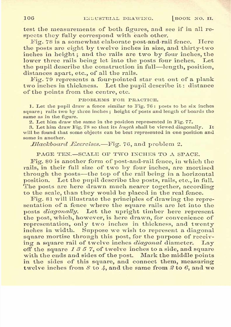
8/2/2019 Drawing Guide Ma Nu Will Rich
http://slidepdf.com/reader/full/drawing-guide-ma-nu-will-rich 112/236
106 INDUSTRIAL DKAWIXG. [BOOK KO. II.
test the measurements of both figures, and see if in all re-
spects they fully correspond with each other.
Fig. 78 is a somewhat elaborate post-and-rail fence. Herethe posts are eight by twelve inches in size, and thirty-two
inches in height ;and the rails are two by four inches, the
lower three rails being let into the posts four inches. Let
the pupil describe the construction in full length, position,
distances apart, etc., of all the rails.
Fig. 79 represents a four-pointed star cut out of a plank
two inches in thickness. Let the pupil describe it :
distanceof the points from the centre, etc.
PKOBLEMS FOK PRACTICE.
1. Let the pupil draw a fence similar to Fig. 76 : posts to be six inches
square ;rails two by three inches
; height of posts and length of boards the
same as in the figure.
2. Let him draw the same in the position represented in Fig. 77.
3. Let him draw Fig. 78 so that its length shall be viewed diagonally. It
will be found that some objects can be best represented in one position and
some in another.
Blackboard Exercises. Fig. 76, and problem 2.
PAGE TEN. SCALE OF TWO INCHES TO A SPACE.
Fig. 80 is another form of post-and-rail fence, in which the
rails, in their full size of two by four inches, are mortised
through the posts the top of the rail being in a horizontal
position. Let the pupil describe the posts, rails, etc., in full.
The posts are here drawn much nearer together, according
to the scale, than they would be placed in the real fence.
Fig. 81 will illustrate the principles of drawing the repre-
sentation of a fence where the square rails are let into the
posts diagonally. Let the upright timber here represent
the post, which, however, is here drawn, for convenience of
representation, only two inches in thickness, and twentyinches in width. Suppose we wish to represent a diagonal
square mortise through this post, for the purpose of receiv-
ing a square rail of twelve inches diagonal diameter. Layoff the square 1 3 5 7, of twelve inches to a side, and square
with the ends and sides of the post. Mark the middle points
in the sides of this square, and connect them, measuringtwelve inches from 8 to 4, and the same from 2 to
,and we

8/2/2019 Drawing Guide Ma Nu Will Rich
http://slidepdf.com/reader/full/drawing-guide-ma-nu-will-rich 113/236
CABINET PERSPECTIVE PLANE SOLIDS. 107
shall have the diagonal square 2Jf.
6 8. Represent this
square as cut through the post, and we shall have the ap-
pearance of the diagonal square mortise which is to receive
the rail placed in a diagonal position. Observe that the lines
2 8 and 4 6 are drawn in the direction of three-space diago-
nals. Below we have the appearance which would be pre-
sented by the rail passing through the post. The rail is so
placed, with reference to the eye of the spectator, that one
side of it appears very wide;while the other side, being
seen very obliquely, appears very narrow.
At A we have represented the posts of the same size as
in Fig. 80, with the square rail passing through them diag-
onally.
At B we have represented the side of the post through
which the rail passes as fronting the spectator as it would
be drawn if the fence were viewed diagonally lengthwise.
In this case the diagonal square mortise would be well rep-
resented, but only one side of the rail would be seen, as in-
dicated by the dotted representation of it. Hence the di-
agonal lengthwise representation of such a fence would not
be a good one.
Fig. 82 is still another form of post-and-rail fence, which
the pupil may describe.
Fig. 83. In this figure the cross-beam, which is supposed to
be designed to sustain a heavy weight, is supported by two
braces, which are framed into the cross-beam and also into
the posts. The under side of the brace on the left is seen so
obliquely that it exposes to view only a very narrow sur-
face.
Fig. 84 is the same pattern of the quadruple or four-band
fret that is used for the setting of an Arabian mosaic in Fig.
43, page 7, of Book No. I. Here, inFig.- 84, the fret alone
is given, and in the solid form. In the lower part of the
figure the half diagonal lines are marked in, to show the
method of representing the thickness of the fret. Each of
these lines, it will be seen, is drawn in a diagonal direction,
and the length of half a diagonal. Understanding this, the
whole figure is very easily executed after the original fret
has been drawn.

8/2/2019 Drawing Guide Ma Nu Will Rich
http://slidepdf.com/reader/full/drawing-guide-ma-nu-will-rich 114/236
108 INDUSTRIAL DRAWING. [BOOK NO. II.
PROBLEMS FOR PRACTICE.
1. Draw a post-and-rail fence similar to Fig. 80, but with the square rails
inserted into the posts diagonally. Let the posts be four inches wide in
front, and twenty inches in diagonal width;and let the edges of the diago-
nally inserted rails be two inches from the edges of the post. Omit the up-
per rail, but show the mortises for it.
2. Draw Fig. 82 of the same diagonal thickness of stuff there represented,
but of only half the front Avidth. Outside dimensions same as in the figure.
Blackboard Exercises. Figures 80 and 82, of the same
real size as described.
PAGE ELEVEN. SCALE OF TWO INCHES TO A SPACE.
Fig. 85 represents a section of a plank picket-fence, ac-
cording to the designated scale. The pickets are made of
stuff four inches wide and two inches thick. The bottom
rail to which they are spiked is four inches by five inches at
the ends;and the upper rail is three inches by four inches.
Observe that if the spikes are driven in horizontally, and
perpendicular to the face of the pickets, they must have a
seemingly upward diagonal direction, as indicated by the
line c a. Hence, if they are driven into the central line of
the rail, their heads must be below that line, as indicated in
the drawing.
Fig. 86 represents a horizontal box eight inches square at
its two open ends, and twenty inches in length, having its
ends framed into and resting upon two vertical pieces of
plank, each sixteen inches square and two inches thick.
Fig. 87 is the Grecian double fret represented in Fig. 30,
page 6, of Drawing-Book No. I.;but here drawn to a larger
scale, and put into the solid form. Observe that the bands
are two inches in thickness, the same in width, and the same
distance apart. Observe, also, that the short corner diag-
onal lines are all drawn to the centres of the small squares ;
and that they thereby measure the required thickness of the
fret, and also give the correct diagonal direction for the
solid.
Fig. 88 is also a Grecian double fret, of the kind seen on
page 5, of Book No. I., Fig. 12. It is here put into the solid
form, and is used for the bordering of a tablet, which is sup-
posed to be ornamented.

8/2/2019 Drawing Guide Ma Nu Will Rich
http://slidepdf.com/reader/full/drawing-guide-ma-nu-will-rich 115/236
CABINET PERSPECTIVE PLANE SOLIDS. 109
Fig. 89 represents a heavy plank chest, thirty-six inches
square on the bottom, and twenty-one inches in height when
the lid is closed. In the top of the chest is placed a tray,
having in it nine partitions. This tray rises three inches
ahove the body of the chest;but its partitions are only two
inches deep ;and when the lid shuts down it incloses within
it the three inches' elevation of the tray. Let the pupil ex-
amine and test all the measurements, and see if the lid will
accurately fit over the tray, and also be even with the out-
side of the chest. What is the thickness of the top of the
lid?
PROBLEMS FOR PRACTICE.
1. Draw the representation of a board-picket fence : rails the same as in
ITig. 85, but the pickets two inches wide, twenty inches long, made of stuff
two inches thick, and placed four inches apart.
2. Draw the representation of a chest similar to Fig. 80. Suppose it to
be thirty-eight inches square ;the body sixteen inches high ; top five inches
high,
made of stuff two inches thick;but the
tray
made of one inch stuff,
and rising three inches above the body. Divide the tray into sixteen square
divisions, each eight inches square (including the partitions) ;and let the
partitions be three inches deep. Place the cover on the farther side, oppo-
site the front.
Blackboard Exercises. Figures 85 and 87, and problem 1.
PAGE TWELVE. SCALE OF SIX INCHES TO A SPACE.
Fig. 90 represents a solid octagonal block, five feet in
length, with a face diameter, on the line 1 2 or 3 4, of three
feet. The octagonal form is the same as that of Xo. 13,
page 2, of Book No. I. Observe that, in drawing the visible
sides of the block, we draw diagonal lines from the points
5, 1, 6, 4, and 7, and in all cases a distance of five diagonals,
representing five feet.
It will be easy to find the solid contents, in cubic inches
or feet, of such a block, after the directions for measuringsurfaces given in the preceding book. Thus, on the scale
of six inches to a space, the front face of Fig. 90 measures
six square feet;and as the length of the block is five feet,
the contents of the block must be five times six, or thirtycubic feet.
Fig. 91 has the same front face as the star figure contain-

8/2/2019 Drawing Guide Ma Nu Will Rich
http://slidepdf.com/reader/full/drawing-guide-ma-nu-will-rich 116/236
110 INDUSTRIAL DRAWING. [BOOK NO. II.
ed within the No. 13 just referred to, or the same as the
star figure No. 11 of Lesson VI., on the same page. As the
face of the star form, Fig. 91, contains an area, according to
the scale, of two square feet, and as the length of the solid
is six feet, the solid contents of Fig. 91 would be twelve
cubic feet.
Fig. 92 is a hexagonal, or six-sided solid, six feet in length,
its two parallel ends being formed of hexagons. The pupil
can now, doubtless, easily calculate the cubic contents of
this figure.
Fig. 93 is an octagonal figure, of the same front outline as
No. 10 of Lesson VIII., page 2, of Book No. I. Six inches
within the series of the outer front lines is another series,
whose distance from the outer lines is regulated by the
points -7, 2, 3, Jh Both the outer and the inner lines are
drawn in the direction of three-space diagonals. This com-
pleted figure forms a hollow octagonal tube, one foot in
length, whose sides are six inches in thickness, with an ex-
treme diameter, both vertical and horizontal, of four feet.
The points 5 and 6, one diagonal space distant from 4 and #,
regulate the drawing of the inner boundary-lines of the far-
ther end. These lines also are drawn in the direction of
three-space diagonals, and are hence parallel to their corre-
sponding front lines.
Fig. 94 is a solid octagonal block, of four feet vertical and
horizontal diameter, and six feet in length. The pupil, re-
ferring back to Book No. I., should now be able to calculate
its cubical contents. Observe that the shading is such as
most clearly to distinguish the several visible sides of the
block.
Fig. 95. The outline of the front face of the block here
represented forms a dodecagon, or figure of twelve sides, the
same as is shown on page 2 of Book No. I.;while the hol-
low or opening through the block is hexagonal. It is easy
to see how the lines bounding the several sides of the block
lengthwise, both on the outside and inside, are to be drawn
all in the direction of diagonals. The outside lines must
all, of course, be of equal length ; and the lines forming the
boundary of the farther face of the dodecagon must be par-

8/2/2019 Drawing Guide Ma Nu Will Rich
http://slidepdf.com/reader/full/drawing-guide-ma-nu-will-rich 117/236
CABINET PERSPECTIVE PLANE SOLIDS. Ill
allel to those forming the boundary of the front face. But
they are made parallel with perfect ease, because their posi-
tion and limits are definitely designated by the ruling of
the paper.
Let the pupil, referring back to the outlines of the same
dodecagon on page 2 of Book Xo. I., calculate the solid con-
tents of Fig. 95.
Fig. 96 has the same front face as Fig. 95, but the solid
formed upon it is only one foot in length. It is thus drawn
in order to show a portion of the inner outlines of the far-
ther end of the block. What are the cubical contents of
this figure?
Fig. 97, having the same outline front form as Fig. 90, is
drawn to inclose an area four times as large as Fig. 90.
(See ELEMENTARY PRINCIPLE, page 54.) This figure is a
hollow octagon, two feet in length, and having its sides six
inches in thickness. Observe that the front outline is formed
by drawing two-space diagonals throughout ; observe, also,
that the inner boundary-lines of the octagon, at both ends,
are the same in direction, but necessarily of less length.
Fig. 98 has the same outline front form as Fig. 93, but is
drawn to inclose an area four times as large as Fig. 93.
(See ELEMENTARY PRINCIPLE, page 54.) It is drawn of
three-space diagonals instead of two. Observe how easily
and accurately in all these figures the inside lines of the
front face of the octagon are drawn, so as to be exactly
parallel to the outside lines. Thus, after taking the point
1, in Fig. 98, the line 1 7 is drawn in the direction of a
three-space diagonal until it intersects the diagonal line 7 10;then the line 2 7 is drawn as a three-space diagonal, and it
will intersect the diagonal 7 10 in the point 7. In like
manner all the front inner-face lines are drawn. Observe,
also, that the points 6 and 5 are designated by being three
diagonal spaces distant from 3 and 4- Then 6 12 and 5 12
are drawn in the direction of three-space diagonals, meetingin the same point, 12.
Fig. 99 is a frame-work which requires little explanation.
Observe that the braces must start at equal distances from
the vertical post ; and that the distance 1 2 must be the

8/2/2019 Drawing Guide Ma Nu Will Rich
http://slidepdf.com/reader/full/drawing-guide-ma-nu-will-rich 118/236
112 INDUSTRIAL DRAWING. [BOOK NO. II.
same as 3 4* The width of the braces, as measured by the
spaces 1 6 and 4 5, must also be the same; although, as the
side edge of the nearer brace is seen most obliquely, it ap-
pears narrower than the farther brace. The pupil should
give the measurements throughout, and imitate the shading
with India ink and the running dot-line.
Fig. 100 represents a foot-bridge resting on piers laid in
cut stone, or in brick three inches thick, six inches wide, and
twelve inches long. These piers are three feet high, laid
up vertically on three sides, four feet by five feet at the base,and two feet by five feet at the top. The extreme width
of the bridge is five feet; length, thirteen feet; top of rail
from top of pier, three feet nine inches. The timbers (called
sleepers) on which the floor is laid are twelve inches vertical
height, and nine inches wide; the flooring is represented as
of about two and a half inch plank ;five of the planks being
each two feet wide, and the two end planks each eighteeninches wide. The posts are six by twelve inches, cut out
so as to let half their thickness (three inches) rest on the
sleepers. The planks come out even with the outer edgesof the posts, and hence they project three inches beyondthe sleepers. The top rails are three by six inches.
Figs. 101 and 102 represent patterns of cubical blocks,
such as are sometimes worked in worsteds of three colors.
We have also seen a carpet of the same pattern, although it
is a very poor pattern for such a purpose. No further di-
rections are required for drawing or shading these figures.
Blackboard Exercises. Figures 90, 93, 96, and 99. Ob-
serve that the farther braces of Fig. 99 run downward in
the direction of diagonals, and the front braces in the direc-
tion of three-space diagonals.
PROBLEMS FOR PRACTICE.
1. Draw an octagonal solid similar to Fig. 90, but whose front face is
only one fourth as large. Be careful to draw the lines of the front face in
the direction of two-space diagonals, and half the length of those in the
figure.
2. Draw a solid similar to Fig. 91, but whose front face shall be four
times as large.
3. Draw a solid similar to Fig. 92, which shall contain four times the

8/2/2019 Drawing Guide Ma Nu Will Rich
http://slidepdf.com/reader/full/drawing-guide-ma-nu-will-rich 119/236

8/2/2019 Drawing Guide Ma Nu Will Rich
http://slidepdf.com/reader/full/drawing-guide-ma-nu-will-rich 120/236
DRAWING-BOOK No. III.
CABINET PERSPECTIVE CURVILINEAR SOLIDS.
IT has been observed that, in all the representations of
objects given in the preceding book, the side of the object
fronting the spectator is drawn in its natural form and pro-
portions this front side being supposed to be in a vertical
position. For example, the front side of the cube at -K,
Fig. 1 of Book No. II., is drawn an exact square. So in
curvilinear solids, that side fronting the spectator is drawn
in its natural form, and is supposed to be in a vertical po-
sition. Therefore, if we wish to represent a cylinder in cab-
inet perspective, and to draw it with the end fronting the
spectator, that end must be represented in its natural form
as a perfect circle.
PAGE ONE. SCALE OF ONE INCH TO A SPACE.
Fig. 1 is a circle drawn from the centre, c, with a radius,
c a, of five inches. It may therefore represent the end of
a cylinder of ten inches' diameter.
Fig. 2. Here c may be taken as the centre of the end of a
cylinder of ten inches' diameter. A cylinder is a solid whose
bases or ends are equal parallel circles, at right angles to the
axis of the cylinder. The axis is the line passing through
the centre of the cylinder at right angles to the ends of the
cylinder. The circumference of a circle is often called its
pe-riph'-er-y; hence, also, we speak of the periphery of a cyl-
inder.
In Fig. 2, if we suppose the cylinder to be ten inches in
length, the line cct,drawn diagonally from the front centre,

8/2/2019 Drawing Guide Ma Nu Will Rich
http://slidepdf.com/reader/full/drawing-guide-ma-nu-will-rich 121/236
CABINET PERSPECTIVE CURVILINEAR SOLIDS. 115
c, will represent the axis of the cylinder; and c will be the
central point of the near end, and d the central point of the
farther end. If, therefore, we describe a circle from the
point d, with a radius of five inches, this circle, only one
half of which could be seen in the solid cylinder, would givo
the true form and position of the farther end of the cylinder.
Connect the extreme edges of these circles by the lines p r
and in n, and we have all the visible outlines of the cyl-
inder.
Fig. 3 is the same as Fig. 2, with the cylinder shaded,
so as to represent it in its solid form. . Observe here that
d, the same as in the preceding figure, five diagonal spaces
from c (ten inches), is the centre from which the visible
boundary of the farther end of the cylinder is described.
From points in the line c d are to be described the several
circular bands which encompass the cylinder; and these
bands will be the same distances apart as are the centres
from which they are described.
Fig. 4. Here a longitudinal right-angled section, embrac-
ing one quarter of the cylinder, is taken away. This shows
the position of the axis, c d, better than it can be seen in the
preceding two figures. From the centre, d, are described,
with the compasses, the visible portions of the farther end
of the cylinder. The sides are drawn in the same manner
as in Fig. 3.
Fig. 5 represents a cylinder of the same size, originally,
as in the preceding three figures, but having, first, one quar-
ter cut away, as in Fig. 4, and then, in addition, all but the
lower left-hand quarter of the middle section is taken away.Measurements of the several sections may be made on the
vertical, horizontal, and diagonal lines in the same manner
as in all plane solids.
Fig. 6. Here, also, the cylinder is ten inches long, as meas-
ured on the line of its axis, c d. The upper halfof the front
portion, four inches in length, is first taken away ;then a
portion of the farther part, but less than a quarter, is re-
moved.
Fig. 7 is the same as Fig. 6, but shaded so as to show the
several parts more distinctly.

8/2/2019 Drawing Guide Ma Nu Will Rich
http://slidepdf.com/reader/full/drawing-guide-ma-nu-will-rich 122/236
116 INDUSTRIAL DRAWING. [BOOK NO. III.
Fig. 8 represents three quarter-sections of a cylinder five
inches in diameter and four inches long.
Fig. 9 represents a cylinder four inches in length and ten
inches in diameter, with an opening four inches square ex-
tending through it longitudinally and centrally. Here c is
the centre of the front end of the cylinder ;and at two di-
agonal spaces from it will be the centre from which the
boundary of the farther end is described. Circles running
around the cylinder are described by the compasses from
points on the axis. Observe that the length of the cylinder
is not only measurable on the axis, but also on the other di-
agonal lines 3^56, etc., which must all be equal each
being the measure of two diagonals.
Fig. 10 represents the outlines of a hollow cylinder four
inches in length and ten inches in diameter, with walls one
inch in thickness. As c is the centre of the front end, we
first describe from it the outer circle, or periphery, of the
cylinder, with a radius of five inches, and then the inner cir-
cle, with a radius of four inches, which leaves one inch be-
tween them for the thickness of the walls. Fromr7,
the
centre of the farther end, we next describe two like circles,
or parts of circles, the visible portion of the smaller circle
being 1 2 3ywhich is the visible portion of the farther inside
boundary.
Fig. 11 is the same as Fig. 10 in outline, but fully shaded.
Fig. 12 represents a cylinder four inches in length and
ten inches in diameter, with a solid cylinder, or axle, four
inches in diameter and twenty inches in length, passing cen-
trally through it the axis of the longer cylinder coinciding
with the axis of the shorter one. Here c d represents the
axis of the short cylinder, and a b the axis of the long one.
The length of either, or both, may be measured in any one
of the several ways mentioned for measuring Fig. 9.
PEOBLEMS FOE PEACTICE.
1. Draw a solid cylinder six inches in diameter and twelve inches in
length.
2. Draw the same, but represent one quarter taken from it, similar to
Fig. 4.

8/2/2019 Drawing Guide Ma Nu Will Rich
http://slidepdf.com/reader/full/drawing-guide-ma-nu-will-rich 123/236

8/2/2019 Drawing Guide Ma Nu Will Rich
http://slidepdf.com/reader/full/drawing-guide-ma-nu-will-rich 124/236
118 INDUSTRIAL DRAWING. [BOOK NO. III.
lines of the bases of the walls in full, and a part of the un-
der side of the arch, which could not be shown in the draw-
ing above it. Figs. 19 and 20 are the same as 1Y and 18,
shaded. In this way an object may be represented in dif-
ferent positions, when it is desirable to show as fully as pos-
sible the construction of its several parts.
Fig. 21 represents a semicircular arch resting on fourpil-
lars, two on a side. The pillars are four feet square and
fourteen feet high, each pair resting on a base one foot in
thickness, six feet wide, and ten feet in length, and sur-
mounted by a cap (capital) of the same dimensions. The
width of the archway, as measured from a to b, is twelve
feet;and the height, from c to
2, twenty-one feet. From the
point x the front semicircles are described;and from y the
semicircles which bound the farther end of the arch are de-
scribed.
The divisions of the front of the arch, 2, 3, 4, &> etc., are
laid oif by the compasses; and from the points of division
straight lines are drawn toward the centre, a?, just as the
lines would tend if the real arch were laid with cut stone.
Let it be observed, also, that the lines 5 7, 6,9 10, etc.
r
drawn in the direction of diagonals, must all be of precisely
the same length in the drawing, according to the scale, a?
they would be in the real arch. In fine, all diagonal, ver-
tical, and horizontal lines in the drawing give, according to
the scale, perfectly accurate measurements of the structure.
Parts of perfect circles may then be measured or calculated
with the same accuracy as in the real object.
PROBLEMS FOR PRACTICE.
1. Draw afigure
similar to
Fig.1
4,
but with a width ofeight
feet infront,
depth of two feet, and total vertical height of ten feet.
2. Draw one like Fig. 19 in all respects, except that a central vertical
section, two feet in depth, is represented as taken out, from right to left,
throughout the entire archway thus leaving the front and the rear of
the archway perfect, and taking out the third part that lies between
them.
3. Eepresent the same inverted thatis, by placing the arch downward.
4. Draw a figure similar to Fig. 21, but of the following dimensions:
Place two columns on a side, each two feet square and twelve feet high, ten
feet apart in front, and each pair six feet apart diagonally. Let each pair

8/2/2019 Drawing Guide Ma Nu Will Rich
http://slidepdf.com/reader/full/drawing-guide-ma-nu-will-rich 125/236
CABINET PERSPECTIVE CURVILINEAR SOLIDS. 119
have a base and cap similar to those in the figure, and also complete the
arch in a manner similar to that in the figure.
Blackboard Exercises.
Figures 14, 19,
and 20; also the
foregoing problems.
PAGE THREE. SCALE OF TWO INCHES TO A SPACE.
Fig. 22. We have here represented a pair of braces rest-
ing upon a platform two inches thick, eight inches wide,
and twenty-eight inches long, and so placed as to be equally
inclined toward a central line, 2 5.
Fig. 23 represents a platform the same as in the preced-
ing figure, but with curvilinear braces placed upon it,and
equally inclined toward a central line, 2 5. In this case,
the bases of the braces, and the height 5 2, being the same
as in the preceding figure, we take any point, as y or c, from
which we can describe, with the compasses, a curve that
will pass through the points 1 and 2. This point, y or c,
may be farther from the left-hand brace, or nearer, according
to the kind of curve that we desire for the brace : but, hav-
ing taken it, we must describe, from the same point, the cor-
responding curve 7 9. Diagonally from y or c we must
take the point z or x, making y z or c x equal to 7 8 ; and
from z or x describe the curve 3 4- This latter curve would
terminate at the point 10, the vertex of the farther face of
the arch, on the under side. For describing the curves of
the right-hand brace, we must take corresponding points at
the left of the platform.
Fig. 24 shows the left-hand brace of the preceding figure,
as drawn by itself alone. Here the point 10 is visible, and
is seen to be in continuation of the curve 3 4>
Fig. 25. This figure represents a semicircular arch eight
inches (y i)in width, two inches' thickness of wall, described
with an extreme radius (c d or y g) of twenty-two inches,
and resting upon a base eight inches wide, two inches thick,
and fifty-two inches in length the whole divided vertically
in the drawing, and at right angles to the face of the arch, so
as to separate arch and platform into two equal halves, six
inches apart. Suppose the two halves to be brought togeth-
er centrally : the arch will thea form a perfect semicircle.

8/2/2019 Drawing Guide Ma Nu Will Rich
http://slidepdf.com/reader/full/drawing-guide-ma-nu-will-rich 126/236
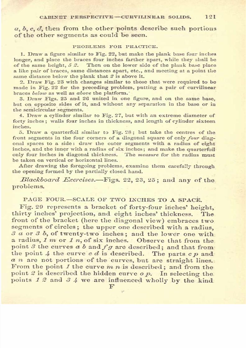
8/2/2019 Drawing Guide Ma Nu Will Rich
http://slidepdf.com/reader/full/drawing-guide-ma-nu-will-rich 127/236

8/2/2019 Drawing Guide Ma Nu Will Rich
http://slidepdf.com/reader/full/drawing-guide-ma-nu-will-rich 128/236
122 INDUSTRIAL DBAWING. j_BOOK NO. III.
and extent of the curve which we wish to describe, just as
in describing the curve of the real bracket; but the diagonal
distance from 1 to 2 and from 8 to 4 is determined by the
thickness of the bracket.
Fig. 30 is the same as Fig. 29, shaded in full.
Fig. 31 is a bracket of precisely the same dimensions as
Fig. 30, but drawn in an inverted position, with the top of
the bracket downward, by which means the hollows, or
curved portions, are represented more fully than in the
preceding figure.
Let the pupil observe that, wherever the thickness of the
bracket is measured, it measures in all parts the same.
Thus the diagonal lines ac,d b,g h,p n, o m, s r, etc., all
measure the same.
Fig. 32 shows the outlines and mode of drawing a plain
and regular trefoil, which is an architectural ornament dis-
posed in three segments of circles, being a conventional
representation of three-leafed clover which is, botanically,
a trefoil plant.
Observe that the points -?,#,#, which are the centres from
which the front curves are drawn, are at the three corners
of an equilateral triangle ;and that the points 4, &, 6, from
which the visible portions of the curves of the farther side
are drawn, are also at the corners of an equilateral triangle,
one diagonal space distant from the front corners.
Fig. 33 shows the same trefoil as Fig. 32, but it is here
cut into and through a cylindrical plank four inches in
thickness, and thirty-six inches in diameter. Observe that
a and b are the central points for describing the outlines of
the cylinder.
Fig. 34. Here we have a quarterfoil of the same dimen-sions as in Fig. 28, but here placed within a cylinder of the
same dimensions as that shown in Fig. 27. Observe that
the central point of the frOnt end of the cylinder is tj and
that from this point, with a radius of eleven inches, we de-
scribe a circle which touches the convex front edges of the
quarterfoil; from the same point t,but with a radius two
inches greater, we describe another circle ; and thus getthe front face of the cylinder. In this manner the inclosing

8/2/2019 Drawing Guide Ma Nu Will Rich
http://slidepdf.com/reader/full/drawing-guide-ma-nu-will-rich 129/236
CABINET PERSPECTIVE CURVILINEAR SOLIDS. 123
cylinder should first be drawn; then the four central points,
a, , <?, d, of the front face of the quarterfoil, should be desig-
nated at the four corners of a diagonal square. These pointsmust be taken according to the size of the quarterfoil that
can be drawn; but it will be observed that they are at
equal distances, vertically and horizontally, from the central
point t. The point x is taken the same as in Fig. 27; and
the points tc,ic,y,2, the same as in Fig. 28. To get the full
effect of this drawing, view it through the opening of the
partially closed hand. (See page 50.)
PROBLEMS FOR PRACTICE.
1. Draw a bracket similar to Fig. 30, but of the following dimensions:
height of bracket, forty inches; projection, 2G inches
; thickness, four
inches;the form of curves, etc.
, according to judgment.
2. Draw the same inverted, similar to Fig. 31.
3. Draw a trefoil on the basis of a triangle of thirty-two inches to a side;
make it
eightinches in
diagonal depthor thickness
;
and let it
have walls,which shall be two inches thick, similar to the walls of the quarterfoil in
Fig. 28.
Blackboard Exercises. The foregoing problems.
PAGE FIVE. SCALE OF TWO INCHES TO A SPACE.
Fig. 35 is a conventional leaf pattern, drawn so as to
representfour leaves whose central surface lines form the
diagonals of a square; then these leaves are represented as
being four inches in thickness, the under sides of the leaves
being of the same form and dimensions as the upper sides.
First : the outline of one side of the upper or front sur-
face of one of the leaves, say A^ is drawn according to judg-
ment. Then it will be easy, as shown in Book No. I., to
draw the other side
symmetricalwith it
bythe aid of the
ruled paper. Thus the curvilinear outlines of the leaf^l,
on both sides of the central line, are a little more than one
space from the point a; nearly three spaces, on both sides,
from the point b; four spaces from the point c; three spaces
from the point c?, etc. In this manner the outlines of the
upper surfaces may all be accurately drawn by the hand
alone.
Next : we have to draw the visible portions of the out-

8/2/2019 Drawing Guide Ma Nu Will Rich
http://slidepdf.com/reader/full/drawing-guide-ma-nu-will-rich 130/236

8/2/2019 Drawing Guide Ma Nu Will Rich
http://slidepdf.com/reader/full/drawing-guide-ma-nu-will-rich 131/236
CABINET PERSPECTIVE CURVILINEAR SOLIDS. 125
Taking the length, a 7, with the compasses, and applying it
to the ruled lines, we find that a 7 is a little more than twen-
ty-eight inches long ; and we find in the same manner thatthe base, 1 9, is about seventeen inches long, as nearly as it
can be measured by the compasses.* Let it be noticed here
that the rule of diagonal measures does not apply to anylines whatever on the surface, 1 7 9; because 1 7 9 is here
supposed to be a vertical surface fronting the spectator,
and not a horizontal surface. See Rule, page 85. Observe
that the point on the under side of the triangle, opposite to
7, is seen at 2; the point opposite to 3 is seen at 4 >the
point opposite to 5 is seen at 6; the point opposite to 7 is
seen at #, etc. all in the direction of diagonals. The farther
face of this solid triangle, being also in a vertical position,
must measure the same as the front face.
Fig. 38 is the same in form and measurement as the pre-
ceding figure, but inverted in position. We here see thebase, 1 2 10 9, quite fully, but no portion of the sides.
Fig. 39 is a curvilinear quadrangular solid, supposed to
be placed with the front side in a vertical position. It.
measures thirty-four inches between the opposite angles
as from 1 to 2 and from 3 to 4, and is four inches in thick-
ness. The curvilinear sides of the front surface are described
with a radius of six diagonals, or about seventeen inches,from the four angles of an erect square ;
and the curvilinear
sides of the farther face are described from the four angles
of another erect square of the same size, whose corners are
one diagonal space from the corners of the first-mentioned
square. Observe that no part of the lower left-hand side or
edge of the solid is visible;but the dotted line, s
?,shows
its position on the farther face of the solid.
Fig. 40 is the same curvilinear solid that is represented in
the preceding figure, but the sides of the front face are here
described from the four angles of a diagonal square. The
* The exact lengths of the lines a 7 and 1 9 can be found, inasmuch as
each forms the hypothenuse of a right-angled triangle, which the ruling on
the paper will show. In calculating their lengths, it will he found that a 7
is a little more than twenty-eight inches long, and that 1 9 is a mere frac-
tion less than seventeen inches.

8/2/2019 Drawing Guide Ma Nu Will Rich
http://slidepdf.com/reader/full/drawing-guide-ma-nu-will-rich 132/236
126 INDUSTRIAL DRAWING. [BOOK NO. III.
points for describing the curves of the farther edges are
f9 A, #, and d, which are each one diagonal space from the
other points.
Fig. 41 is a solid semicircular and rectangular architect-
ural band, the front vertical face of which is two inches in
width, and the thickness or depth of which is four inches.
Taking the curvilinear section A, it will be seen that the
two curves of the front face are described from the point #,
with a radius of three and of four inches;and that the two
curves of the farther face (a part only of each being visible)
are described from the point 4, one diagonal space from #,
with the same radii as the front curves. The points 5 and 6
are, in like manner, the centres for describing the curves of
the section J5. The points for the other curves are also
given. The front face is shaded with a light wash of India
ink, and the other parts by darker washes and the pencil.
PROBLEMS FOR PRACTICE.
1. Draw the leaf forms B, (7,and D at short distances apart, but in their
present relative positions, and give to each a thickness of eight inches.
'Shade them as in Fig. 3G.
2. Draw Fig. 37 of the same dimensions as described;but let the cen-
tral line, a 7, be in a horizontal position, twenty-eight inches in length
tue point 7 being at the right hand.
3. Draw Fig. 38 of the same dimensions as Fig. 37, but having the cen-
tral line, 4 5, m a horizontal position the point 5 being at the left hand.
4. Draw an erect square frame of forty inches to a side, in the clear that
is, having a clear measure of forty inches on the inside;
let the depth be
eight inches, and the thickness of the material one inch. Within this frame
place a solid similar to Fig. 39, having its curvilinear sides described from
the inner corners of the frame with a radius of twenty inches;and let the
solid also be eight inches in thickness. Shade the frame and the inclosed
solid
properly.
Blackboard Exercises. Fig. 41, as much of it as can be
put on the board, and problem 4.
PAGE SIX. SCALE OF TWO INCHES TO A SPACE.
Fig. 42 represents five quarter-sections of the rims of
wheels, the front faces or edges of which are all in the same
verticalplane, fronting the spectator. If the rims were en-
tire, they would represent what is called a nest, lying one

8/2/2019 Drawing Guide Ma Nu Will Rich
http://slidepdf.com/reader/full/drawing-guide-ma-nu-will-rich 133/236
CABIXET PERSPECTIVE CURVILINEAR SOLIDS. 127
within another. As the front edges all lie in the same
plane, they are all described from the same centre, a, each
rim being made two inchesin
thickness. Thefarther
edgesof the rim are likewise in one and the same plane ;
and as
the rims are four inches wide, they must be described from
a point, ,one diagonal space from a. The lines crossing the
front edges of the rims all radiate from the point a.
Fig. 43 represents the side walls of a beveled tub, whose
vertical height, when placed on its bottom, is sixteen inches;
extremediameter across the
top, twenty-eightinches
;
and
extreme diameter across the bottom, forty inches.
The top of the tub being supposed to be in a vertical plane
fronting the spectator, and c being its central point, the
outer circle of the top is described from c, with a radius,
c #, of fourteen inches;while the inner circle is described
with the radius, c g, of twelve inches.
Now,as the tub is to be sixteen inches in extreme
height(or depth), we take the point x, four diagonal spaces from c;
and the point x is then the central point of the bottom of
the tub. Hence, with x as a centre, and with a radius, x b,
of twenty inches, we describe a circle for the outer circum-
ference of the bottom of the tub, thus making its diameter
forty inches. With a radius two inches less, we describe
from xthe circle for the inner circumference of the bottom
of the tub, which gives us the visible part, dsf, of this inner
circumference of the bottom. The lines r p and m n are
drawn tangent to (that is, touching) the outer circumfer-
ence of the top of the tub, and the outer circumference of
the bottom of the tub.
Suppose, now, that we wish to put circumference lines
around thetub,
andpassing through
certainpoints, , 4,
and 6, of the surface. In the same proportions that the line
i k is divided by the points , 4, and 6>,divide the axis line
c x by the points .?, ,and 5 ; then, with one point of the
compasses in the point 1, and the other extended to the
point 2, describe the first curve;with one point in
<<?,and
the other in4->
describe the second curve;with one point in
5,and the other in
6,describe the third curve. The visible
portion of the inside of the tub is viewed so obliquely that

8/2/2019 Drawing Guide Ma Nu Will Rich
http://slidepdf.com/reader/full/drawing-guide-ma-nu-will-rich 134/236

8/2/2019 Drawing Guide Ma Nu Will Rich
http://slidepdf.com/reader/full/drawing-guide-ma-nu-will-rich 135/236
CABINET PERSPECTIVE CUBVILIXEAE SOLIDS. 129
PROBLEMS FOB PBACTICE.
1 . Draw five quarter-sections of the rims of wheels, similar in all re-
spects to those in Fig. 42, but placed in the upper right-hand quarter of thecircle.
2. Draw the outlines of a bottomless tub similar to Fig. 43, but of the fol-
lowing dimensions. Extreme upper (front) diameter, twenty-four inches;
vertical height, measured on the axis of the tub, twenty-four inches;ex-
treme diameter of bottom of tub, thirty-four inches;thickness of walls, one
inch.
Blackboard Exercises. The foregoing problems.
PAGE SEVEN. SCALE OF TWO INCHES TO A SPACE.
Fig. 47 represents a cubical block, twenty -eight inches
square, having semicircular grooves of four inches' radius
running diagonally through the centres of its upper, lower,
and right and left hand sides, with a circular aperture of
four inches' radius
running
from the front face
diagonallythrough the centre of the block.
Observe that the centres a, #, c, d, <?,/",from which the
semicircles on the front and on the farther side are de-
scribed, are situated at the middle point of the edges of the
cube, just where they would be placed for marking out the
semicircular grooves on the real cube.
Figs.
48
maybe
supposed
to be cut out of a block twen-
ty-eight inches in height (m n or e g) ; twenty-eight inches
in depth (m o or e/); and thirty-two inches in width (m e
or n(/).
The figure consists of a frame-work having four
corner posts of two by four inches, supporting ahalf-cylin-
der above and one below, with their concave surfaces out-
ward, the whole cut out of the block. The thickness of the
walls of the
half-cylinders
is four inches. Their semicircular
ends are described from the points tf, , c,and d. The point
dtfor describing the farther end of the lower half-cylinder,
must evidently be at the middle of the farther lower edgeof the block, just as c is at the middle of the front lower
edge. But c is eight spaces, horizontally, to the left of the
corner #/ so must d be eight spaces, horizontally, to the left
of the corner h. If the pupil will carry out all the meas-
urements, just as they are in the real object, he will find
F2

8/2/2019 Drawing Guide Ma Nu Will Rich
http://slidepdf.com/reader/full/drawing-guide-ma-nu-will-rich 136/236
130 INDUSTRIAL DRAWING. [BOOK NO. III.
but little difficulty in the accurate representation of the
most intricate plans and patterns.
Fig. 49 represents two cylinders, lying, horizontally and
diagonally, side by side on a frame-work of twenty-four by
thirty-two inches. As the centres of the farther ends of
these cylinders are at the points b andc7,
the length of their
axes, a b and c d, and, consequently, the length of the cylin-
ders, is twenty-four inches. The cylinders are placed, at
both extremities, four inches from the ends of the frame.
Complete the circle of two-inch radius, of which d is the
centre, and the circle will strike the frame at the same dis-
tance from the farther end that the circle described from c
strikes it from the front end.
Fig. 50. This figure consists of two portions, A and BA being the same as B inverted.
Taking, first, the portion marked A: the two semicircu-
lar curves a and #, of the front face, are described from their
common centre, y ; while the two marked c and d, of the
farther face, are described from their common centre, z. In
a similar manner, the two semicircular curves a and,of
the front face of B, are described from w; and the curves
c and d, of the farther face, are described from a*.
Fig. 51 consists of a series of the same forms as A, of the
preceding figure, here framed together. The pupil shouldnow be able to describe this frame-work in full, and to des-
ignate the respective centres from which the several pairs
of curves (front curves and rear curves) are described.
Fig. 52 consists of a series of the same forms asJB, of Fig.
50, here framed together; or the same as Fig. 51 inverted.
The pupil should now be able to describe it in full. In
making a drawing of such figures either in copying, or in
drawing from a description the front portions should be
drawn first.
Fig. 53 is a combination of the two figures 51 and 52;
requiring merely the placing of the two figures in proper
position, and the completing of the vertical corner posts,
which are left short in Figs. 51 and 52.
In making a drawing ofFig. 53, the front face should first
be drawn, then the right-hand side; then the other parts

8/2/2019 Drawing Guide Ma Nu Will Rich
http://slidepdf.com/reader/full/drawing-guide-ma-nu-will-rich 137/236

8/2/2019 Drawing Guide Ma Nu Will Rich
http://slidepdf.com/reader/full/drawing-guide-ma-nu-will-rich 138/236
132 INDUSTRIAL DRAWING. [BOOK NO. III.
lines through the centre, x, hereby dividing the rim into eight
equal parts ;and on each side of these several lines lay off a
space of three inches, and draw the lines representing the
thickness of the spokes, terminating them, in one direction,
by the inner circle of the rim, and in the other direction bythe outer circle of the hub. This completes the outlines of
the front vertical face of the wheel.
5th. As the rim is to be thirty inches wideband the hub
and spokes of the same diagonal extent, we take x y, thirty
inches, for the axis, and also for the thickness or width of
the wheel. Then y will be the centre of the farther verti-
cal face of the wheel.
6th. From the centre, y, and with the radius y z,of five feet
nine inches, describe the outer circumference of the farther
face of the wheel; and from the same point y, with a radius
six inches less, that is,with a radiuses, describe a circle (only
half of which, h ij, will be visible) for the inside circumfer-
ence of the farther face of the rim; then, with a radius, y r,
of two feet, describe a circle (of which k Us a part) for the
outer circumference of the farther face of the hub; and
finally, with a radius, y p, of one foot, describe a circle (of
which m n is the only visible part) for the inner circumfer-
ence of the farther face of the hub. All the necessary cir-
cles will thus be completed drawn in the very same man-
ner, from the two centres, #, y, of the axis, that they would
be drawn from on the real wheel.
7th. The positions and correct width of the front faces of
the spokes having been marked out under the fourth divi-
sion, we have only to draw from their extremities the diag-
onal lines 1 2, 3 4-,5 6, 7 8, etc., across the inside of the rim
and the outside of the hub, and the lines for the farther vis-
ible edges of the spokes, and the outlines of the spokes, so
far as they are visible, will be completed.
8th. Shade the several parts in such a manner as to make
each part distinct from the others, but at the same time
paying as much attention as you can, consistent with dis-
tinctness, to the laws of light and shade. The light in this
drawing, as in most of the preceding, comes diagonally from
the upper left-hand corner.

8/2/2019 Drawing Guide Ma Nu Will Rich
http://slidepdf.com/reader/full/drawing-guide-ma-nu-will-rich 139/236
CABINET PERSPECTIVE CURVILINEAR SOLIDS. 133
Observe with what accuracy all the parts, in accordance
with the scale laid down, and with the principles of repre-
sentation adopted, maintain their correct measurements, thesame as in the real object. Thus all measurements at right
angles across the outside or the inside of the rim of the real
wheel, and across the outside or the inside of the hub, meas-
ure the same, thirty inches. So, also, in the drawing, all the
diagonal lines across the rim or the hub as 1 2,3 ^5 6, 7 8,
v w, etc. measure precisely the same, five diagonal spaces,
or thirty inches.Let this wheel be viewed as directed on page 50. The
pupil should not only draw this wheel, but also one of a dif-
ferent size, and with the spokes arranged differently.
PROBLEM: FOR PRACTICE.
1. Draw a wheel, similar to Fig. 54, of the following dimensions: Ex-
treme diameter, ten feet and a half; rim, thirty-six inches wide and three
inches thick ; the cylindrical nave, or hub, thirty-six inches in diameter,
three inches in thickness, and thirty-six inches in length ;and having eight
flat spokes or radii, each three inches thick, and the same width as the rim
and hub.
Blackboard Exercise. Let the pupil plan and draw a
wheel similar to that described in the problem, and of such
size as the board will permit.
TAGE NINE. SCALE OF THREE INCHES TO A SPACE.
Fig. 55 represents a wheel eleven feet and a half in ex-
treme diameter; extreme width of double rim and double
hub, four feet; thickness of rim, three inches; extreme di-
ameter of the hub, four feet, and diagonal extent of the two
parts, four feet;thickness of rim of the hub, three inches
;
thickness of the broadpaddle-like spokes,
threeinches, andwidth four feet.
This figure consists oftwo similar wheels, the second being
placed immediately back of the first, and each having its
separate rim and hub, but the two being united in one wheel
by the broad paddle-like spokes, which are common to both.
1st. In drawing this figure, draw the front wheelfirst, in
the same manner thatFig.
54 was drawn wbeing
the cen-
tre of the front face of the wheel, and x the centre of the

8/2/2019 Drawing Guide Ma Nu Will Rich
http://slidepdf.com/reader/full/drawing-guide-ma-nu-will-rich 140/236
134 INDUSTRIAL DRAWING. [BOOK NO. III.
opposite side. Draw the circles lightly with the compasses ;
then draw lightly, in like manner, the front and rear circles
of the farther wheel, from their centres y and z.
2d. Observe that the eight broad spokes are arranged in
a manner different from those in Fig. 54, there being no
spokes on the diagonal lines 3 12 and 7 a ; and we have
placed none on these lines, because, in these positions, there
could be no side view of the spokes that are in the direction
of 3 12, as there is none in Fig. 54. Thisis, therefore, a bet-
ter arrangement of these portions of the wheel.
3d. In order to arrange the eight spokes equidistant from
one another, and intermediate between the centrally verti-
cal, horizontal, and diagonal lines of the wheel, first draw
these lines lightly, and mark their points, as 1, 3, 5, 7, 9, 11,
etc., on the circumference of the front face of the wheel;
then take the points 2, ^, 6, 8, 10, etc., intermediate between
them, and connect the opposite points by light lines passing
through the centre, w. On each side of these latter lines
lay off half a space (an inch and a half), and draw lightly
the lines which determine the front width of the spokes.
Each pair of these lines passes equidistant on both sides of
the centre, w. The extreme ends of the spokes are then all
drawn diagonally across both parts of the rim, and the oth-
er ends of the spokes are drawn in like manner across both
parts of the hub. The dotted continuations of the lines show
where the lines would appear if the parts which obstruct
the view were transparent.
Observe how the broad spokes are let in, centrally, be-
tween the two rims which compose the hub, and that theyare let in the exact depth of the rims, three inches. The
portions that are let in are, therefore, continuous with the
inner sides of the rims of the hub. Every part of this wheel
will show beautifully when viewed as directed on page 50.
If the pupil will be careful to have all the measures cor-
respond with the measures of the real wheel of the given di-
mensions, and will connect those points, and those only, that
are connected in the real wheel, he will have no difficulty
in drawing this, and all similar representations of real ob-
jects, with mathematical accuracy.

8/2/2019 Drawing Guide Ma Nu Will Rich
http://slidepdf.com/reader/full/drawing-guide-ma-nu-will-rich 141/236
CABINET PERSPECTIVE CURVILINEAR SOLIDS. 135
PAGE TEN. SCALE OF THREE INCHES TO A SPACE.
Fig.
56 is a
drawingof what is called a
croicn-wheel,which is a wheel with cogs or teeth cut out of the rim, and
get at right angles to the plane of the wheel. See a differ-
ent representation of this same wheel in Fig. 23 of Book
No. IV.
In this figure the ends of the projecting cogs or teeth,
thirty-two in number, form the vertical front face of the
wheel,
which has w for its centre;and the extreme diameter
of the wheel 1 5 or 3 7 is eleven feet. The rim, including
the teeth, is thirty inches wide and -three inches in thick-
ness, and the cogs are one foot in length ;the four support-
ing arms (or spokes) of the wheel, which are six by twelve
inches, are set back even with the farther face or side of the
wheel, and are back eighteen inches from the ends of the
cogs
: x is the centre of the farther vertical side, and hence
to x, the proper axis, is thirty inches in length ;but v x, the
axis of the short hub, is only twelve inches in length. The
hub is eighteen inches in diameter, as measured from m to w,
and its rim is three inches in thickness. Through the hub
passes an axle on which the wheel turns, twelve inches in
diameter and sixty inches in length, having s t for its axis.
1st. In
drawing
a figure with the dimensions
given
for
this wheel, first take some point, as w, for the centre of the
front face, and with a radius, w 3, of five and a half feet, de-
scribe the outer front circumference of the circle of cogs ;
and then, with a radius three inches less, describe the inner
front circle, which gives the thickness, three inches, of the
cogs. From x describe two like circles for the farther edgeof the rim.
2d. Divide the front circumference into eight equal parts,
by the dotted vertical, horizontal, and diagonal lines, radi-
ating from the centre, w; then, with the compasses, make
eight equal divisions in each of these parts, which will give
to each part four equal cogs, with spaces between them of
the same width as the cogs.
3d. As the cogs are to be twelve inches in length, take
the point y, twelve inches diagonally from?,and with the

8/2/2019 Drawing Guide Ma Nu Will Rich
http://slidepdf.com/reader/full/drawing-guide-ma-nu-will-rich 142/236
136 INDUSTRIAL DRAWING. [BOOK NO. III.
same radius as w 3, describe a circle; and also describe one
with a radius three inches less; and these two circles will
give the true measurable length of the teeth, both on theinside and on the outside of the rim.
4th. Nowif,
in the real wheel, the cogs bevel outward
from the centre, w, they must be so drawn here, in the follow-
ing manner: The lines at the ends of the cogs that limit
their width (not thickness) must all be directed toward
their common centre, w as c ?o, a w, 3 w, etc.;but the cor-
responding lines at the base of the cogs must be directedtoward their common centre, y as I y, 9 y, g y, p y, etc.
just as they are in the real wheel.
5th. All lines that bound the teeth lengthwise as h i,j I;
o r, etc. must be drawn in the direction of diagonals. These
lines, however, are drawn next after the end lines that limit
the width of the cogs; and, when drawn, they fix the posi-
tion of the base lines of the cogs.6th. From the point v, the centre of the front face of the
short hub, describe the two circles, one with a radius of nine
inches, and the other with a radius of six inches, for the
front face of the hub;and from
a;,with a radius of nine
inches, describe a circle (only a small part of which is seen)
for the outer circumference of the farther face of the hub.
From s and t are described the circles for the ends of theaxle.
7th. As v is the centre of the vertical circle which limits
the front ends of the spokes, from v, with a radius of five
feet and three inches, describe a circle for that purpose. The
central lines of the front faces of the spokes must then pass
through v, and the width of the spokes is laid out at equal
distances on each side of these central lines. The shadingis similar to that of the preceding two figures.
The dimensions of the wheel are well seen in the dotted
squares AB CD, EFQ II, which bound its front and rear
vertical faces.
PAGE ELEVEN. SCALE OF THREE INCHES TO A SPACE.
Fig. 57 represents the face or side of a ratchet wheel, awheel which has teeth like those of a circular saw. The

8/2/2019 Drawing Guide Ma Nu Will Rich
http://slidepdf.com/reader/full/drawing-guide-ma-nu-will-rich 143/236
CABINET PERSPECTIVE CURVILINEAR SOLIDS. 137
teeth may be either long and sharp-pointed, or short and
more blunt in appearance; but in either case the inner
edges of the teeth are not directed toward the centre of thewheel.
1st. This figure represents the face or side of a wheel fifty-
four inches in extreme diameter, having x for its centre.
After describing the outer circumference, take any required
distance on a diameter, as 3 d, and from x, with the radius
x d, describe the circle d ef, which is to limit the length of
the teeth.2d. Divide each quarter of the circumference into as many
equal spaces as there are to be teeth in it. From the centre,
x, describe an inner circle, a bc, large or small, according to
the amount of bevel that is to be given to the teeth.
3d. From the points of division in the circumference, as
#,#,4, etc., draw lines tangent to (touching) the inner circle,
r.<5
seen in the drawing such as 3 a, 8 c, etc. ; and also,from the same points of division in the circumference, draw
the tooth lines 3 g, h o, etc., intersecting the former tangen-tial lines on the second circle. But the drawing itself will
explain every thing that is needed to be understood.
Fig. 58 represents not only the side view of a ratchet
wheel, but the dimensions, also, of all its parts, in length,
breadth, and thickness.
Fig. 58 represents a ratchet wheel twelve feet in extreme
diameter, having a rim fifteen inches wide and six inches
thick, into which thirty-two teeth are cut, to a depth of nine
inches. It has a hub forty-two inches in diameter, with a
central cylindrical opening for a shaft, or axle, twelve inches
in diameter : and twelve spokes, of three by six inches, and
thirty-six inches long, set at equal distances apart, connectthe rim and the hub.
1st. Here x is the centre of the vertical front face or side
of the wheel, and y the centre of the farther side. As the
circle 1111, described from x, with a radius of six feet,
limits the points of the teeth on their front face, so the circle
222%, described from y, with the same radius, limits the
points of the teeth on the farther side of the w
T
heel. There-fore, if we divide the outer circumference, 1111, into thirty-

8/2/2019 Drawing Guide Ma Nu Will Rich
http://slidepdf.com/reader/full/drawing-guide-ma-nu-will-rich 144/236
138 INDUSTRIAL DRAWING. [BOOK NO. III.
two equal parts, as in Fig. 57, and from all the points of di-
vision draw diagonal lines, like d g,f%, m n, etc., intersect-
ing the circle 2222, we shall have the lines of the edges
of all the teeth.
2d. We get the required bevel for the front edges of the
teeth, in the same manner as in Fig. 57, by describing the
circle a a a from the centre, a?,and drawing all lines, such as
d CjfSj m p, etc., tangent to that circle. But these latter
lines are limited by the circle 3 3 8, which we describe from
x, limiting the length of the front edges of the teeth. Acircle, 4 4 4 9
described from?/,
with the same radius, limits
the edges of the teeth on the farther side;but all these
edges, like g A, 2 4, n'r, etc., whether concealed from view
or not, must be drawn tangent to the rear circle, b b b, de-
scribed from?/,
and corresponding to the front circle, a a a.
By following these simple principles, describing all the
circles, and drawing all the lines, just as they would be in
the real wheel, the dimensions of every tooth are accurately
represented, and all measure precisely the same.
3d. The twelve spokes, each three inches wide in front,
and six inches in thickness, are laid out by dividing each
quarter of the inner circumference of the rim into three
equal parts, and then laying out the width equally on each
side of these divisions. By this arrangement of the spokes
all show to good advantage.
The pupil should not only draw this wheel, but also one
of a different size, and with a greater number of teeth.
Fig. 59 represents a chain-pulley wheel, the links of the
chain being adapted to fit over the projecting triangular
cogs. The design is sufficiently illustrated by the drawing,
without the necessity of any description; but the pupil
should fully describe the wheel.
PAGE TWELVE. SCALE OF TWO INCHES TO A SPACE.
Fig. 60 represents a windlass, viewed diagonally length-
wise. It consists of a cylindrical shaft, XX, twelve inches
in diameter and eighty-eight inches in length ;four inches
from the two ends of which are two drums, W W, each
twenty-eight inches in diameter and twelve inches in thick-

8/2/2019 Drawing Guide Ma Nu Will Rich
http://slidepdf.com/reader/full/drawing-guide-ma-nu-will-rich 145/236
CABINET PERSPECTIVE CURVILINEAR SOLIDS. 139
ness. Projecting from the centre of the circumference of
each drum, at right angles to the axis, are eight spokes or
levers, three inches by four inches in size, and with a pro-
jection of ten inches beyond the drum.
A smaller shaft, or axle, Y y, six inches in diameter, pro-
jects, centrally, sixteen inches beyond the ends of the larger
shaft, and, immediately beyond the ends of this larger shaft,
rests in two bracing supports, each eight inches wide, fitted
to receive the axle.
At A the front drum is drawn separately, together withthe end of the shaft and the projecting axle, but without
the spokes or levers, and without the support in which the
axle rests. Here a is the centre of the axle, where it con-
nects with the shaft, and also the centre of the end of the
shaft, while b is the centre of the front face of the drum, and
c the centre of the farther face or side.
At J? is a separate drawing of the support in which thefront axle rests. The timber forming the base in which the
braces rest is forty inches in length, four inches in vertical
thickness, and eight inches in width. The supporting braces
are two by eight inches, and about twenty-three inches in
length above the base. The tie-brace at the top is cut out
in a semicircular form, six inches in diameter, to receive the
axle.At C is a representation of the drum, TFJ with the spokes
in their places. It is here drawn separately for the purposeof showing the method of placing the spokes accurately in
the centre of the cylindrical surface of the drum. This draw-
ing may be made in the following order:
1st. Take some point, a, as the centre, from which, with a
radius of fourteen inches, describe the circumference of thenearer and visible end of the drum
;and from d, twelve
inches diagonally from,on the axis, with the same radius,
describe the farther circumference, only half of which is vis-
ible.
2d. Xow, as the spokes to be inserted are three inches
wide on their face or front side, and four inches diagonally,
theymust be inserted in the
central third portion of thecylindrical surface of the drum. We therefore take -a d,

8/2/2019 Drawing Guide Ma Nu Will Rich
http://slidepdf.com/reader/full/drawing-guide-ma-nu-will-rich 146/236
140 INDUSTRIAL DRAWING. [BOOK NO. III.
representing the line of the axis of the drum, and divide it
into three equal parts by the points b and c; and from b
and c as centres, with a radius of fourteen inches, we de-
scribe the two dotted circles encompassing the drum. These
two circles mark out the central third part of the cylindric-
al surface of the drum, as they would appear to the eye if
the drum were transparent. The spokes must therefore
start out from the drum between these circles, and touching
them.
3d. These spokes we may consider four in number, equi-
distant from one another, passing at right angles through
the axis of the drum, and presenting eight projecting arms
to our view. For convenience, we will suppose the circum-
ference of the nearer dotted circle to be divided into eight
equal portions by the vertical line 1 2, the horizontal line
5 6, and the two diagonal lines 8 4 and 7 8, giving us the
equidistant points /, /i, J, m, o, q, 9, and 10. From /, as a
starting-point, measure off any desired distance, as/<7, and
take g as the point for the intersection of a corner of the
spoke with the dotted line. From h measure off the same
space toi,and the same from^' to
A?,from m to
??,from o to
p, etc., for points at which the corners of spokes pass throughthe circumference of the drum.
4th. From each of the several points, g, i, 7j, ??, p, etc.,
measure off three inches backward on the dotted line, as
g 11, i 12, etc., for the width of the face of each spoke.
Connect the points that are directly opposite, as Up, g 13,
etc., by very light lines extended indefinitely, every pair of
which will pass equidistant on each side of the central point,
b, and will represent the front faces of the spokes as passing
through the axis of the drum.
5th. The length of the projecting arms, or spokes, may be
determined by circumscribing a circle around the centre, b.
Here the circle, which may be called the nearer face circle
of the spokes, is drawn with a radius of twenty-four inches,
giving ten inches for the length of the spokes, and passing
through the points e, 8, x, etc. Now, as the spokes are four
inches in diagonal width, we describe another circle with the
same radius from c (four inches diagonally fromb), passing

8/2/2019 Drawing Guide Ma Nu Will Rich
http://slidepdf.com/reader/full/drawing-guide-ma-nu-will-rich 147/236
CABINET PERSPECTIVE CURVILINEAR SOLIDS. Ill
through the points 5, 3, 1, 8, w, y, etc., thus limiting the di-
agonal width of the spokes. Suppose, now, that the corner
facelines
of the spokes, as g e, 16 r, etc., extend to the nearerface circle e 8 x. From the intersections of these corner
lines with this nearer face circle, giving the points t, r, v, z, x,
etc., we draw lines diagonally, as t u, r s, eI,v w, x y, etc.,
which give us the side boundary-lines of the ends of the
spokes.
6th. The lines 16 17, 11 18, 12 19, etc., showing the in-
tersections of the sides of thespokes
with the surface of the
drum, we also draw diagonally for all lines that are par-
allel in the real wheel must be parallel in the drawing. .
The outlines of the spokes are thus completed all accu-
rately drawn in their proper places, as projecting from the
central third part of the surface of the drum.
At D the several parts described in the sections ^1, B, and
C areput together, resting
on a timberplatform.
Let the
pupil verify the following measures according to the scale.
1st. The distance, x y, between the drums, isfifty-six
inches. The distance, c d, on the axis, between the centres
of the inner faces of the two drums, must give the same
measure.
2d. As each drum is twelve inches in thickness, the dis-
tance,r
z,between the outer faces of the
drums,must be
eighty inches. The distance, bg, between the points on the
axis, from which the circumference of these outer faces are
described, must give the same measure.
3d. As the large shaft extends four inches beyond the
extreme faces of the two drums, the length of the shaft,
whether measured diagonally on its surface or on its axis,
must beeighty-eight
inches. The farther end of thelarge
shaft is concealed from view, but its position can be easily
determined by counting twenty-two spaces diagonally from
the point 5.
4th. As the tops of the bracing supports of the axle are
in immediate contact with the ends of the shaft, the dis-
tance beticeen the inner faces of the tops of these supports
must also measureeighty-eight
inches.
5th. As each of the bracing supports is eight inches in

8/2/2019 Drawing Guide Ma Nu Will Rich
http://slidepdf.com/reader/full/drawing-guide-ma-nu-will-rich 148/236
142 INDUSTRIAL DRAWING. [BOOK NO. Ill,
width, the distance, st,between the extreme faces of the
tops of these supports, must be one hundred and four inches.
We thus get the point t, and the outlines of the concealed
top of the farther brace.
Cth. As we have the point 1 at the bottom of the nearer
brace, we now know that the corresponding point 2 of the
farther brace must be one hundred and four inches from it
diagonally that is, twenty-six diagonal spaces. The dis-
tance from 3 to 4 must measure the same.
We have been thus particular in describing the drawingof this figure for the purpose of showing that every part
may be drawn with the most perfect accuracy, and so as to
show its exact measurement. With the aid of the ruled
drawing-paper all such drawings may be executed with
great rapidity; and any required degree of modification,
also, from the plain angular forms, may be given to them.
Thus the spokes may be round, or even tapering, and light-
er than here shown, and all the parts may be modified,
while at the same time accuracy of representation may be
adhered to, provided the very plain principles of this mode
of representation are clearly understood.

8/2/2019 Drawing Guide Ma Nu Will Rich
http://slidepdf.com/reader/full/drawing-guide-ma-nu-will-rich 149/236
DRAWING-BOOK No. IV.
CABINET PERSPECTIVE MISCELLANEOUS
APPLICATIONS.
I. DIFFERENT DIAGONAL VIEWS OF OBJECTS.
Ix the preceding two books on Cabinet Perspective, ob-
jects have been represented not only as viewed diagonally,
with their principal surfaces in vertical and horizontal posi-
tions, but as viewed diagonally from one particular point,
which point is supposed to be diagonally at the right of the
object, and above it. But although, for the purpose of
avoiding confusion, it is best to represent all objects from
this one point of view whenever it can be done to advan-
tage, yet objects may be represented diagonally in cabinet
perspective equally well from any one of four points of
view, as will be seen from the drawing on the first page of
Book No. IV.
PAGE ONE.
1st. Upper right-hand view. In division A the objects
are represented as viewed diagonally from above, and at the
right, the same as in all the drawings in the preceding twobooks. The arrow, m, is represented as coming from the po-
sition, at an infinite distance away, from which the objectsin A are viewed.
2d. Lower right-hand view. In division B the objects are
represented as viewed from below, and at the right ; and
here the arrow, n, is represented as coming from the posi-
tion, at an infinite distance away, from which the objectsare viewed. It will be observed that the bracket,/, is best

8/2/2019 Drawing Guide Ma Nu Will Rich
http://slidepdf.com/reader/full/drawing-guide-ma-nu-will-rich 150/236
144 INDUSTRIAL DRAWING. [iJOOK NO. IV.
represented in its true position from the point of view here
taken.
3d. Lower left-hand view. In division C the objects are
represented as viewed from beloio, and at the left; and here
the arrow, o, is represented as coming from the point from
which the objects are viewed.
4th. Upper left-hand mew. In division D the objects
are represented as viewed from above, and at the the left/
the arrow, p, being represented as coming from the position,
at an infinite distance away, from which the view is taken.
Thus two of the views are represented as taken from
above, one from the right and the other from the left;and
the other two views are represented as taken from below, in
like manner. In this way we get inside views of the curves
of the four brackets;but all of the brackets might have
been drawn equally well according to the plan of division A,
if they had been placed in proper positions for the purpose.
In A the bracket, c,is inverted, for the purpose of showing
to the best advantage the inside curves;and the brackets
/*, y, and h might have been drawn in similar positions.
II. GROUND-PLANS AND CABINET-PLANS OFBUILDINGS.
PAGE TWO. SCALE OF ONE FOOT TO A SPACE.
Fig. 1 is the ground-plan of a building, whose outer walls,
one foot in thickness, embrace an extent of eighteen by twen-
ty-six feet. It will be seen that the lined paper is admira-
bly adapted to ground-plans or surface representations, as
it is only necessary to adopt any convenient scale, when
the plan may be laid down with perfect accuracy without
any measurement, by simply counting the spaces. In a
ground-plan, like Fig. 1, we can show the position and thick-
ness of the walls and partitions, and the width and position
of doors and windows, etc.
Fig. 2 is a cabinet-plan of the walls, doors, windows, etc.,
of Fig. 1;the whole being represented from the fotmda-

8/2/2019 Drawing Guide Ma Nu Will Rich
http://slidepdf.com/reader/full/drawing-guide-ma-nu-will-rich 151/236
CABINET PERSPECTIVE MISCELLANEOUS. 145
tions upward to the extent of three feet. Observe that all
the measures in Fig. 2 are the same, according to the st-:ik'
adopted, and the principles laid down for cabinet drawing,as in Fig. 1. Thus, in Fig. 2, the length of the side wall, 1 2,
is twenty-six feet;and the distance, 1 4, is eighteen feet
the same, in both cases, as in Fig. 1. But in Fig. 2 it is
shown that the windows in the front room come down with-
in six inches of the bottom of the wall, while those in the
back room come down to within two feet and a half of the
bottom of the wall. These are features which can not beshown in a ground-plan.
Fig. 3 is another ground-plan, representing a building
with two rooms, one fourteen by sixteen feetj and the other
thirteen by sixteen. The position for a stair-way is given in
a corner of the large room, and the position for a shelf is
given in the other. Rectangular openings for fire-places
are also given in the partition wall; but we can not showany thing more than a mere ground-plan in this kind of
drawing, and must look to the next figure for any thing like
details.
Fig. 4 is a cabinet view of the plan of Fig. 3, embracingnot only the ground-plan, but the walls, bench, stair-way,
platform to entrance, etc. a//, in fine, that belongs to the
plan of the building, to the extent of three feet above thestone foundations, while the height of the stone wall above
the earth is shown also.
In making a drawing of this kind it is best to begin at
the top, and work downward, tracing every thing lightly at
first. The walls may be made of any desired height; and
the only objection to making them then-full height is that
the front wall will then obscure the rear wall. It is well,
sometimes, to draw the front wall and the right-hand wall
only two or three feet high, and represent the other two of
their full height, with beams, joists, etc., projecting a short
distance from them. Or any section of the building maybe represented separately, and a scale larger than that used
for the walls may be adopted for portions that require a
minute representation. In this manner the most elaboratebuilding may be fully represented, even to the most minute
G

8/2/2019 Drawing Guide Ma Nu Will Rich
http://slidepdf.com/reader/full/drawing-guide-ma-nu-will-rich 152/236
146 INDUSTRIAL DRAWING. [BOOK NO. IV.
details, and with far greater accuracy than could be attain-
ed by description alone.
Fig. 5. At A are represented a stair-way and platform,
with the side to the front;and at B the same are repre-
sented with the stairs presenting the front view. Observe
that the measurements in the one case are the same as in
the other the distance 5 2 being the same as 6 ., an^ * $
the same as 3 7, etc.
PROBLEM FOR PRACTICE.
(This may be omitted by the younger pupils.}
It is required to draw, in cabinet perspective, a building similar to the
ground-plan of Fig. 3, but of the following dimensions : Length of building
(1 2\ forty feet;width (1 3\ twenty-four feet
;thickness of walls, eighteen
inches;room on the left, twenty by twenty-two feet in the clear
;room on
the right, seventeen by twenty-two feet in the clear. Draw the front wall,
division wall, and wall on the right-hand side, only three feet high, but the
wall on therear,
and left-handside,
eleven feet
high.Put in the
openingsfor the windows, a and b, in the centres of the ends of the rooms, three feet
from the floor, four feet wide, and seven feet high ;the door, c, two feet
from the partition wall, four feet wide, and seven feet high ;let a beam one
foot square at the end rest upon the rear wall and left-hand side wall;
let
a beam of the same size project from the rear beam four feet over the par-
tition wall;and let one project forward from the upper corner above 2,
four feet; and let one extend from the corner above<?,
four feet to the
right, over the front wall. Carry a tier of four shelves, two and a half feet
apart, twelve feet long, and two feet wide, across the window, up against
the rear wall and right-hand corner of the room on the right, the top of the
lower shelf being two and a half feet from the floor. Carry a flight of eight
stairs, four feet wide, with one-foot risers and one-foot tread, up against the
rear wall of the room on the left, onto a platform four feet square in the cor-
ner;and then have four stairs running from the platform toward the front,
up to the top of the wall. Let there be one supporting post, six inches
square, at the angle where the stairs turn, and one to support the end of the
last stair, three feet six inches from the wall, and coming out flush with the
end of the stair.
Let the other windows, doors, etc., be similar, in size and position, to those
in Tig. 4.
PAGE THREE. SCALE OF ONE FOOT TO A SPACE.
Fig. 6 is the ground-plan of a building twelve feet in ex-
treme width, and thirty-four feet in length, with a platformentrance to the front of two by six feet, and three steps,

8/2/2019 Drawing Guide Ma Nu Will Rich
http://slidepdf.com/reader/full/drawing-guide-ma-nu-will-rich 153/236
CABINET PERSPECTIVE MISCELLANEOUS. 147
each a foot wide, ascending to it. There are two rooms,
each ten by twelve feet, with a hall between of six by ten
feet, and openings four feet wide in the partition walls, for
sliding-doors, leading from the hall into the two rooms. The
jambs of the fire-places bevel outward. At A the ground-
plan of the fire-places is drawn on a larger scale, showingthe exact bevel of the jambs.
Fig. 7 is the same as the preceding figure, here changedto the cabinet-plan, and drawn to the same scale as Fig. 6.
The ground-plan of the walls represented in Fig. 6 is, in Fig.
7, transferred to a stone foundation, which is raised one foot
above the ground at the corner.7,and two feet at the corners
2 and 3. Hence the front steps, which have six-inch risers
and one-foot tread, must rise a distance of two feet.
At B is a cabinet view of the fire-place, drawn to the
same scale as the ground-plan in A. Observe how the fig-
ures of the one correspond to the figures of the other in rel-
ative position, and that the measures are the same in both.
Fig. 8 represents a series ofplatform structures of different
elevations. Thus, if we begin with the level at J, we as-
cend toward the left an inclined or sloping plane until we
rise three feet, to the level of H. Rising six inches from Jf,
we step onto the platform Gr or J5f/ four steps, each of six
inches' rise, then bring us onto the platform I or F; eight
steps, each of six inches' rise, then bring us to the level of
the platform Z>.
Now it would be difficult to ascertain whether JEis high-
er than D or not, if we did not know, ovfind out, the heightof the box-like frame-work on which the flooring, E, rests,
and likewise its projection beyond the sides of the frame.
The size of this frame-work is sixteen feet square ; and thefloor, here represented as six inches in thickness, projects
one foot on all sides, except toward Z>, where there is no
projection. The frame-work (without the floor) rises four
feet above the corners 5 and 7, and six feet above the corner
6. Hence the upper corners of the frame-work would be
seen at the points 1 and #, the former four feet vertically
above 5, and the latter six feet vertically above 6; and theother corners at the points 3 and Jh at the intersections of the

8/2/2019 Drawing Guide Ma Nu Will Rich
http://slidepdf.com/reader/full/drawing-guide-ma-nu-will-rich 154/236
148 INDUSTRIAL DBAWING. [BOOK NO. IV.
dotted lines. Now if we connect these four points, as shoxvn
in the drawing, we have the outlines of the top of the frame-
work.
We have now to put a floor six inches thick on the top
of this frame-work, and projecting one foot beyond all its
sides except toward D. If we extend 4 1 one half a diag-
onal space, that is,one foot, to o, the latter point will be the
lower left-hand corner of the projecting floor;and the point
7i,six inches above it, will be the upper left-hand corner of
the floor. Extend the side lines of the top of the frame one
foot beyond their intersections at 2 and 5, and we shall have
points through which the lower side lines of the projecting
floor wrill pass, to make the other lower visible corners t and
v. Draw from t and v lines six inches vertically upward,and we shall have the upper right-hand corners of this pro-
jecting floor. In order to see fully the truth of this de-
scription, it would be well, first, to draw the outlines of the
top of the frame lightly, without the flooring, E, and after-
ward to put on the flooring.
As it requires eight steps, of six inches each, to rise from
the platform I to Z>, D is four feet above I; and as the
frame-work ofE\$ four feet high above the level of the cor-
ner 5, and as on this frame-work is placed a flooring six
inches thick, it follows that D is six inches below E. The
farther end ofD is even with the farther side of the frame-
work of E.
The posts a and b are flush, on both their outer sides, with
the corners of the frame-work above which they are placed ;
the posts d and r are flush with the right-hand side of the
frame-work, and consequently are one foot from the right-
hand edge of the flooring ;while the posts p and c are
flush with the front and rear sides of the frame-work, and
are one foot each from the front and rear edges of the
flooring.
The posts on the platform E are three feet high above
the floor. The posts on the platform D are also three feet
high ;but on the latter posts is a rail six inches thick, so
that the top of the rail is even with the top of the railing
ofM

8/2/2019 Drawing Guide Ma Nu Will Rich
http://slidepdf.com/reader/full/drawing-guide-ma-nu-will-rich 155/236
CABINET PERSPECTIVE MISCELLANEOUS. 149
At C are the outline walls of a building, the outer walls
being two feet in thickness. At L is seen the opening into
a pit, extending downward below the flooring.Observe that the window openings in the frame ofE are
the same in relative position, number, size, etc., on the right-
hand side as on the front, and that there is the same real
width of window-sill represented on the right-hand side as
on the front.
To master the drawing of the platforms in Fig. 8 with
the projection of E on three sides, and no projectionto-
ward D with the arrangement of the posts, etc., the whole
should be drawn on a larger scale.
PROBLEM FOR PRACTICE.
Draw a figure similar to Fig. 8, but with the following measures : Let
the frame on which the flooring of E rests be twenty-seven feet square.
Height of frame from corners 5 and 7 six feet, and from corner 6 eight feet.
On this frame place a floor one foot in thickness, and one foot projec-
tion on all sides except toward Z>, where there is to be no projection.
Posts of platform E four feet high above floor, six by twelve inches in size,
and arranged as in Fig. 8. Platforms I and F six feet wide. Platform Z>,
and steps ascending to it, eight feet wide;and a sufficient number of steps,
each six inches' rise and twelve inches' tread, for D to be six inches below
E. Top of railing ofD to be even with top of railing of E. Let there be
four window openings, or recesses, in front, and the same number on side
ofE,
eachthree
feet
wide andfour feet
high,a foot and a half from the
top of the frame ; and let the depth of the recesses be one foot. These
window openings to have three feet space between them, and those nearest
the corners to be three feet from corners. In other respects make the
structure similar to Fig. 8, omitting (7.
III. CYLINDRICAL OBJECTS IN VERTICALPOSITIONS.
The representations of circles, wheels, cylinders, etc., in
cabinet perspective, have thus far been made on the suppo-
sition that the axes of the cylinders, etc., lie in a horizontal
position, although placed diagonally with reference to the
point
from which the view is taken;and the vertical
cylin-drical ends have been drawn perfect circles, as though they

8/2/2019 Drawing Guide Ma Nu Will Rich
http://slidepdf.com/reader/full/drawing-guide-ma-nu-will-rich 156/236

8/2/2019 Drawing Guide Ma Nu Will Rich
http://slidepdf.com/reader/full/drawing-guide-ma-nu-will-rich 157/236
CABINET PERSPECTIVE MISCELLANEOUS. 151
tration : First, rule the upper surface of the cube to corre-
spond to the ruling on the front face. Then all the lines,
and their intersections, on the upper surface, will correspondto those on the front face. Mark any required number of
points on the front face, through which the circle passes,
and mark the corresponding points on the upper surface,
and then through these latter points draw the ellipse, and
it will correspond to the circle. Thus, if the ellipses be
accurately drawn, they will pass through the points 2, 4,
8, 10, 14, 16, 0, 22, etc., of the top and right-hand side of thecube. More points may be taken, if required, and thus the
ellipses may be drawn quite accurately by hand. This
mode must give an accurate cabinet representation of a cir-
cle drawn on the top and side of a cube. View the whole
figure through the opening of the partly closed hand for
a half- minute or so, and the ellipses will gradually appear
as perfect circles.
But the two side curves of each of these ellipses may be
quite accurately drawn in the following easy manner. Sup-
pose we wish to draw the ellipse in the cabinet square
B C F E. Place one point of the compasses in the point
B, and extend the other to the point a, the centre of the
opposite long side;and with the compasses thus extended
strike a curve across B F, the diagonal of the square, anddot the point b. Then, with one point of the compasses in
F) and with the same stretch, dot the point d, corresponding
to b. With the compasses still spread as before, first with
the point ata;,
and afterward at a, strike the curves inter-
secting on the right at m. Then, with one point of the
compasses in m, strike the side curve a a; of the ellipse.It
may be prolongedin
the direction of ato 7.
Then, withthe points of the compasses respectively in 18 and 12, the
centres of the other two sides, with the same stretch as be-
fore, strike the curves that intersect at n; and from n as a
centre describe the other side curve 12 18, prolonging the
curve to about the point 19. Half the distance from d to
B will give the point 21 of the ellipse,on the diagonal ;
and half the distance from b to J^willgive
thecorrespond-
ing point 9. The diagonal distance from 9 to 21 is also

8/2/2019 Drawing Guide Ma Nu Will Rich
http://slidepdf.com/reader/full/drawing-guide-ma-nu-will-rich 158/236
152 INDUSTRIAL DRAWING. [BOOK NO. IY.
equal to the distance from B to a the distance first laid
off on the compasses.
In a similar manner the side curves of the upper ellipse
may be described, by laying off the same distance as be-
fore, from B to o, and describing the intersecting curves
from x and o, etc. This method will give a dose approxi-
mation to the true side curves.
The ei.d curves of the ellipse should be drawn by the eye,
after first marking the points of the curve on the diagonal,
as before directed. Fig. 9 should be referred to as a guide
for drawing the forms of all similar end curves in ellipses
thus situated;but yet it will seldom be necessary, and not
often desirable, to draw cabinet ellipsesin those positions.
It will generally be found most convenient to draw the
curves either in the positions and in the manner shown in
Book No. III., or after the following plan.
II. ELLIPSES ON RECTANGULAR BASES.
Fig. 10. Suppose that the cube, Fig. 9, should be so
viewed that neither the right-hand side nor the left-hand
side could be seen at all, but that the top of the cube should
appear directly above the front face, and of the same width
as in Fig. 9. The whole would then be seen as in Fig. 10,
in which the front face is the same in all respects as in Fig.
9;and the top has the same width, 12, as o A in Fig. 9
but the right-hand side of the cube is not visible. Nowthe top of the cube, supposed to be viewed from an infinite
distance, is rectangular; and it is of the same length, from
left to right, as the front face;and its apparent width, 12,
is just half the width or height of the front face. Hencethe top or upper side, A B C D, as thus viewed, has a
length twice its width;and the circle that should be drawn
on the top of a cube thus viewed would show as a perfect el-
lipse, whose lesser* diameter, 12, is just one half the length
of the greater* diameter, 6 18.
This ellipse, representing a circle forming the end of a
* The lesser diameter of an ellipse is called its conjugate diameter, and
the greater is called its transverse diameter.

8/2/2019 Drawing Guide Ma Nu Will Rich
http://slidepdf.com/reader/full/drawing-guide-ma-nu-will-rich 159/236
CABINET rEr.SPECTIYE [MISCELLANEOUS. 153
vertical cylinder, may be drawn after the manner first indi-
cated in Fig. 9, by dotting points to correspond, in relative
position, to the points marked on thecircle
below. The el-
lipse is here drawn in this manner, by dotting the points,
and then drawing the curve through them by hand. All
the points in the ellipse that are accurately marked in this
way must be correct. As the circle, described with a ra-
dius often spaces, passes through the twelve points 0, 2,4,
8, 10, 12, 14, 16, 18, 20, 22, so must the ellipse above it,if accu-
rately drawn, pass throughthe
corresponding twelve points,numbered in like manner.
Side Curves. But the side curves, at least, of this and of
all similar ellipses, may be very accurately drawn by the
compasses in the following manner. Place one point of the
compasses in A, and extend the other to 6, the middle of
right-hand side of the cabinet square A B C D (or place
in .Z> and extend to18) ; then,
still
continuingthe
pointin
A, with the other point strike the central vertical line, 12
prolonged, in 10. Then, with one point of the compasses in
ic,and the other extended to 12 above, describe the curve
9 12 15. Then, with one point in C, and the other extended
to 18 (half way between A and D), strike the line 12 pro-
longed above 12, for the point on the opposite side to cor-
respondto the
point w;from which
point,thus
found,and
with the other point of the compasses extended to 0, de-
scribe the curve 3 21. The two side curves will thus be
drawn very accurately.
End Curves. The end curves may be best drawn by
hand, in the following manner, by the aid of guide circles.
Thus :
Onthe line 6 18 take
any point, v,so that v 6 shall be
equal to v 9, and from v describe a circle passing through
the points 9,6,3: this circle will then serve as a guide for
drawing the end curve of the ellipse, which must pass a lit-
tle within the circle, and at the same time be a natural and
graceful continuation of the side curves. The other end
curve is drawn in a similar manner.
Note. The representation given in Fig. 10 may be called upper vertical
rectangular perspective. But if the spectator were horizontally to the rifjht
G2

8/2/2019 Drawing Guide Ma Nu Will Rich
http://slidepdf.com/reader/full/drawing-guide-ma-nu-will-rich 160/236

8/2/2019 Drawing Guide Ma Nu Will Rich
http://slidepdf.com/reader/full/drawing-guide-ma-nu-will-rich 161/236
CABINET PERSPECTIVE MISCELLANEOUS. 155
we describe an ellipse within the square EF G H, in the
same manner that we described the ellipse within the square
ABCD. The visible portion,C r D, of this ellipse, whoseside curve is described from the point p, we have drawn
with a firm line;the other portion, Z> t C, which would
be invisible unless the cylinder were transparent, we have
drawn with a slightly dotted line.
Fig. 12. Here the solid cylinder, the method of drawing
which has been fully described in Figs. 10 and 11, is shown
as completed and shaded. Any vertical cylinder, of any
given dimensions, may be easily drawn by the method here
described, and with such accuracy that all its parts may be
readily measured.
Let it be observed that as the rectangle A B C D of
Fig. 10 corresponds to the rhombus A B C D of Fig. 9,
therefore the line C B of Fig. 10 measures the same
(in cabinet perspective) as the diagonal line C B of
Fig. 9; and 12 and D A of Fig. 10 the same as 12
and D A of Fig. 9, etc. Therefore we have the follow-
ing rule for representing objects in rectangular cabinet per-
spective :
RULE. When, in drawing objects in RECTANGULAR cabinet
perspective, a diagonal space is changed to a vertical space,
the latter, when thus used to represent a horizontal distance,has the same measure as the former.
Fig. 13. The upper part of this figure is drawn on the
plan of Fig. 10 and Fig. 12. The lower part is a horizontal
cylinder whose end directly fronts the spectator. Observe
that the length of the horizontal cylinder, as measured from
1 to 2, is sixteen inches; length of the short vertical cylin-
der only four inches.
PROBLEMS FOR PRACTICE.
1. Draw a vertical solid cylinder after the plan of Fig. 12, whose diame-
ter shall be thirty-six inches, and whose -axis, or length, shall be eighteen
inches.
2. Draw a horizontal cylinder whose diameter shall be twenty inches,
and length twenty-four inches, with one end directly fronting the spectator,
as in Fig. 13 ; and at the farther end of this cylinder, and starting evenwith the top of it, draw a vertical cylinder of the same dimensions as the

8/2/2019 Drawing Guide Ma Nu Will Rich
http://slidepdf.com/reader/full/drawing-guide-ma-nu-will-rich 162/236
156 INDUSTRIAL DRAWING. [BOOK NO. IV.
horizontal cylinder. The horizontal cylinder is to project forward from the
front vertical side of a cube twenty inches square; and the vertical cylinder
is to rise from the upper side of the same cube.3. Draw a cube twenty-four inches square, in right horizontal rectangular
perspective. Centrally placed on the right-hand side of it, extend out
horizontally to the right another cube sixteen inches square ;and on the
right-hand side of .this draw a horizontal cylinder twelve inches in length
and sixteen inches in diameter. Shade all the front surfaces light, and
the right-hand side surfaces dark. Then view the drawing as directed on
page 50, except that the eye of the spectator should be centrally to the
right of it. Also place the length vertically, and view it in that position
until it seems to stand out boldly from the paper.
PAGE FIVE. SCALE OF TWO INCHES TO A SPACE.
Fig. 14. It is required to make a drawing of the top of
a hollow vertical cylinder eighty inches in extreme diame-
ter, and whose sides are eight inches in thickness.
1st. Let A B C D be a rectangular cabinet square of
eighty inches to a side. Within it describe an ellipse
touching the centres of its four sides, after the manner
shown in Figs. 10 and 11. Here w will be the point for
describing the side curve 112; and x for describing the
other side curve 8 i 4; while t and s are the points for de-
scribing the guiding circles for the outer end curves.
2d. Now, as the walls of this hollow cylinder are to be
eight inches thick, the inner circle that bounds the walls on
the inside must be eight inches within the outer circle; so we
take o r, k I,v p, and ij, each eight inches within the ellipse
first drawn, and complete the rectangular cabinet square
EF G II eight inches, on all sides, within the outer square.
Within this smaller square describe an ellipse touching the
centres of its four sides, and we shall have the outlines of
the top of the hollow cylinder, as required.
3d. This inner ellipse is drawn in all respects like the
outer one. Thus y and z, found as before shown, are the
points from which its side curves are described; and m and
n are the points from which the guiding circles for drawing
the ends of the ellipse are described.
4th. Observe that the walls of the cylinder appear the
thinnest at the points ij and k I, and that at the points o r
and v p they appear to be double the thickness of ij and k/,

8/2/2019 Drawing Guide Ma Nu Will Rich
http://slidepdf.com/reader/full/drawing-guide-ma-nu-will-rich 163/236
CABINET PERSPECTIVE MISCELLANEOUS. 157
as they would naturally appear when viewed from the given
point above and in front of the cylinder.
Fig. 15. It is required to make a drawing of a thin flat
ring, forty-
eight inches in diameter and four inches in
width.
1st. Take the horizontal line A B, of twenty-four spaces,
representing forty-eight inches, and on it construct the rect-
angular cabinet square A JB C D. A D or JB C will then
represent forty-eight inches also.
2d. Describe the ellipse 1234 within this square, andtouching the centres of its four sides. This ellipse wr
ill
represent the top circle of the ring. The central line, 4 ,
must be extended upward, so as to get the point from which
the lower side curve is to be described.
3d. As the bottom circle of the ring is four inches below
the top circle, it is to be described within a square four
inchesbelow
thesquare which
contains thetop
circle.
Therefore lay on a second square, E F G- J7, four inches
below the top square, and within it describe the ellipse
5678, touching the centres of its four sides at the points
5, 6, 7, 8. The outlines of the drawing, which may now be
shaded, will thus be completed.
4th. Notice that 1 5 and 3 7 are straight vertical lines,
representingthe width of the
ring,four
inches;and that
the curve 9 6 10 would touch the points 5 and 7 if it could
be seen throughout.
5th. Observe that this ring is drawn as having no appar-
ent or measurable thickness.
Fig. 16. It is required to make a drawing of a ring forty-
eight inches in diameter, four inches in width (or height, as
hereviewed),
and four inches in thickness.
1st. Draw the cabinet square, A. IB C D, of the requisite
dimensions, and within it describe the ellipse,1 2 3 4> for the
upper outer circumference of the ring.
2d. Take the cabinet square, EFGr H, also of forty-eight
inches to a side, four inches below the first-mentioned square,
and within it draw an ellipse in all respects like the ellipse
5 6 7 8 ofFig. 15,
with theexception
thatonly
thefront
half of the ellipse in Fig. 16, as denoted by the figures , 8, 7,

8/2/2019 Drawing Guide Ma Nu Will Rich
http://slidepdf.com/reader/full/drawing-guide-ma-nu-will-rich 164/236
158 INDUSTRIAL DRAWING. [BOOK NO. IV.
is visible; the farther half being concealed by the thickness
of the ring.
3d. In order to get the lateral thickness of the ring, take
a cabinet square, I JI X, four inches within the square
A BCD, and describe the ellipse, 9 10 11 1#, touching the
centres of the four sides of this inner square. The thickness
of the ring, as seen on its upper horizontal edge, will then
be represented by the space between the two ellipses 1234and 9 10 11 12.
4th. It now remains to describe the visible portion of the
lower inner circle of the ring. As this must be drawn four
inches below the upper inner circle, take the cabinet square,
U V W JT, four inches below the square I JK X, and
within it describe an ellipse touching the centres of its
sides. Of this ellipse, a little less than the farther half,
op r, will be visible.
Observe the quadrangle (four sided figure) at each corner
of the drawing. The two outer corners of each of the four
quadrangles are the corners of the two cabinet squares
within which the two outer ellipses are drawn;and the two
inner corners are the corners of the two squares within
which the two inner ellipses are drawn. Similar quadran-
gles may be found in the drawings of all cylinders on a
rectangular basis ; and these quadrangles are excellent
guides for the formation of the squares within which the
several ellipsesare to be drawn. Observe that, in all simi-
lar drawings of hollow cylinders, the distance A E, or B F,or C 6r, or D H, represents the height of the cylinder.
The four ellipses described in this figure, representing
the four circles that form the outlines of the real hollow
cylinder, are all the guides that are required to draw anyhollow cylinder, of any definite .height, diameter, and thick-
ness of walls, in the vertical position represented by a rect-
angular cabinet square, as distinguished from a diagonal
cabinet square. A little practice will enable one to draw
these ellipses with great facility, while the ruling of the
drawing-paper insures accuracy. These four ellipses an-
swer to the four circles used in drawing a hollow cylinder
in diagonal cabinet perspective.

8/2/2019 Drawing Guide Ma Nu Will Rich
http://slidepdf.com/reader/full/drawing-guide-ma-nu-will-rich 165/236
CABINET PERSPECTIVE MISCELLANEOUS. 159
Fig. 17 is the same in outline as Fig. 16, but is here shaded,
the better to show the effect. Observe the four corner
quadrangles,
which are here retained as guides for the four
cabinet squares within which the ellipses are to be drawn.
The points from which the upper side curves are drawn are
below the border of the page. Observe that the point 1 is
the centre of the upper two squares and ellipses; and that
the point 2 is the centre of the lower two squares and el-
lipses ;while the line 1 2 represents the axis of the short
cylinder
or ring.
Fig. 18 represents the same ring as in Fig. 17, but with a
portion of the front of the ring cut out vertically, and at
right angles to its inner and outer surfaces.
PROBLEMS FOR PRACTICE.
1. Draw a vertical hollow cylinder whose extreme diameter shall be
fifty-two inches; length of axis (height of cylinder), twenty inches, and
thickness ofwalls,
six inches.
2. Draw two hollow cylinders after the plan of Fig. 13, page 4. Let each
of the cylinders be thirty-two inches in diameter, sixteen inches in length,
and the walls four inches in thickness. Remember that it is to be drawn
on a scale of "two inches to a space." This measure applies to both ver-
tical and horizontal lines on the front end of the horizontal cylinder, while
it means four inches to a space on lines representing horizontal lines run-
ning directlyfrom the spectator. Thus, in Fig. 13, each of the lines 1 3,
and 4 $i an(i 8 9 measures twelve inches;and 2 6 measures four inches
;
but G 7 measures twelve inches, and 1 2 measures sixteen inches.
PAGE SIX. SCALE OF TWO INCHES TO A SPACE.
Fig. 19. It is required to draw, in rectangular cabinet per-
spective, a hollow vertical cylinder, forty inches in extreme
diameter, fourteen inches in height, the walls four inches
thick, and to be encompassed by three bands, each two
inches wide, one even with the top, one even with the bot-
tom, and the third intermediate between the other two.
1st. Draw the hollow cylinder after the manner described
in preceding figures. Referring to Fig. 19, let the pupil ob-
serve that it is the cabinet square A J3 C D that incloses
the top of the cylinder, and the square EF'
G JET that in-
closes the bottom. Hence E and .F are fourteen inches
vertically below A and 7?, and Hand G are fourteen inches

8/2/2019 Drawing Guide Ma Nu Will Rich
http://slidepdf.com/reader/full/drawing-guide-ma-nu-will-rich 166/236

8/2/2019 Drawing Guide Ma Nu Will Rich
http://slidepdf.com/reader/full/drawing-guide-ma-nu-will-rich 167/236
CABINET PERSPECTIVE MISCELLANEOUS. 161
urement applicable to each. Observe, also, that the two
cabinet squares, AB CD, EF G II, of Fig. 20, correspond
to the similarly lettered cabinet squares of Fig. 19.
Fig. 21. It is required to draw a horizontal wheel of the
following dimensions in rectangular cabinet perspective:
Wheel to be fifty-sixinches in extreme diameter; horizontal
thickness of rim, four inches;width of rim (or height, as
it lies horizontally), two inches;a hub at the centre six-
teen inches in extreme diameter, same vertical thickness as
the width of the rim, and with a central eight-inch circular
opening through it for the axle. There are to be eight
spokes between the hub and rim, each four inches in hori-
zontal thickness, and same vertical width as the rim, radia-
ting from the centre of the hub, and at equal distances apart.
1st. Draw the upper and lower ellipses which form the
boundaries of the rim in the manner described for drawing
hollow cylindersin
preceding figures.2d. Draw the boundaries of the hub in the same manner.
3d. From the centre, q, with a radius of twenty-eight
inches, describe a circle passing through the extreme points
o and t of the wheel. Mark the points w, s,>, and n for the
diagonals of the circle;then these points, together with the
centrally dividing points m, t, r, and o, will divide the circle
into eight equal parts. Fromeach of the
eight given points,
beginning at m and moving to the left around the circle,
lay off with the compasses any required distance, as m 1
and n 2, and mark accordingly the points 1, 2, 3, 4-> etc., for
the positions in the wheel in which the spokes are to be rep-
resented. Then, as the spokes are to be each four inches
in horizontal thickness, take with the compasses a width of
twospaces,
andlay
off that distance on the circle from the
points /, 2, 3, 4, 5, etc., and we shall have the distances 1 x,
2 y, S 2, 4 -10, etc., to represent the horizontal thickness of the
spokes. From the given points draw the dotted lines per-
pendicularly toward the horizontally dividing line ot,and
from the points where any pair of these dotted lines strike
the outer upper ellipse of the wheel, draw lines to the corre-
sponding opposite pointsofthe
ellipse,
and the
apparent uppersurface width of the spokes will be given. Observe that the

8/2/2019 Drawing Guide Ma Nu Will Rich
http://slidepdf.com/reader/full/drawing-guide-ma-nu-will-rich 168/236
162 INDUSTRIAL DRAWING. [BOOK NO. IV.
nearer these spokes approach, in lengthwise position, a line
running directly from the spectator, the wider their upper
surfaces appear, and the narrower their side views appear.
To get the apparent vertical thickness of the spokes, and
the lines of their junction with the inside of the rim and the
outside of the hub, we have only to draw lines vertically
downward from the points where the upper lines of the
spokes intersect the ellipses of the rim and hub, and then
draw the lower lines of the spokes as shown in the drawing.
The same result would be attained by supposing the spokes
to extend through the rim, as shown by the dotted lines.
Fig. 22 is another illustration of the principles of dividing
the ellipse into any number of equal parts, as set forth in
Fig. 21.
It is required to make a drawing of a vertical tub, of the
following dimensions, in rectangular cabinet perspective:
The tub is to be twelve inches in outside height; forty inches
in extreme diameter; having a bottom one inch thick from
the level of the chimes below;
its sides to be vertical, and
composed of twenty-four staves of uniform width, and two
inches thick; and the tub is to be encompassed by two
hoops, each two inches wide, the upper one one inch from
the top of the tub, and the other even with the bottom.
1st. Draw the hollow cylinder for the walls of the tub
the same as in preceding figures, with the exception of the
inside lower ellipse.
2d. Describe the semicircle, 6 6, and with the compasses
divide it into twelve equal parts. This is easiest done by
commencing at 0, and dividing each quarter as from to
8, then from 3 to 6, etc. into three equal parts. This will
give the corresponding points, 1, 2, 3, 4, &9 6-> on each side of
0. From these points draw dotted lines vertically down-
ward until they intersect the outer upper ellipse ;also sup-
pose these dotted lines to be extended until they intersect
the nearer half of this outer upper ellipse. These twenty-
four points of intersection with the outer ellipse will be the
points of division for the apparent outer surface width of the
twenty-four staves.
3d. The top dividing lines of these staves must all be di-

8/2/2019 Drawing Guide Ma Nu Will Rich
http://slidepdf.com/reader/full/drawing-guide-ma-nu-will-rich 169/236

8/2/2019 Drawing Guide Ma Nu Will Rich
http://slidepdf.com/reader/full/drawing-guide-ma-nu-will-rich 170/236
164 INDUSTRIAL DEAWING. [BOOK NO. IV.
PAGE SEVEN. SCALE OF THREE INCHES TO A SPACE.
Fig. 23. The same crown-wJieel that is shown in Fig. 56,
page 10, of Book No. III., is here drawn with its axis, t s,
in a vertical position. The rectangles A B C D and
EF G II represent the squares A B C D and EF G II
of Fig. 56.
Here w is the centre of the tipper horizontal surface of the
wheel, across the ends of the cogs ;and the wheel, as in Fig.
56, measures eleven feet in extreme diameter from 16 to 16.
From the centre, w, we therefore describe the two ellipses
which give the thickness of the ends of the cogs, as in Fig.
56 we described the two circles from the corresponding cen-
tre, 10.
Twelve inches below w we take the point y, from which,
as a centre, we describe the two ellipses which determine
the length of the cogs, and also the thickness of the wheel
between their bases. Six inches below y we take the point
u, which must be on the level of the tipper surfaces of the
four arms which support the rim;and from v as a centre
we describe the ellipse which gives the limit for the ends
of these arms at their upper extremities. As these arms are
to be twelve inches in vertical height, or thickness, we take
a point a;, twelve inches below v, from which we describe
the ellipse which limits the lower extremities of the arms,
and also gives the inside lower boundary of the wheel.
As the axle on which the wheel turns extends fifteen
inches beyond both the upper and the lower face of the
wheel, the point s must be the centre of one end of the axle,
and the point t of the other; and as the diameter of the axle
is twelve inches, we have the dimensions of the ellipse de-
scribed around s for one end of the axle. The other end, t,
of the axle can not be seen.
The point v is the centre of the upper end of the hub,
which is eighteen inches in diameter.
As the wheel is to contain thirty-two cogs, at uniform
distances apart, and of the same width as the spaces be-
tween them, we divide each quarter of the semicircle, 16 16,
into eight equal parts; and from the points of division on

8/2/2019 Drawing Guide Ma Nu Will Rich
http://slidepdf.com/reader/full/drawing-guide-ma-nu-will-rich 171/236

8/2/2019 Drawing Guide Ma Nu Will Rich
http://slidepdf.com/reader/full/drawing-guide-ma-nu-will-rich 172/236
166 INDUSTRIAL DRAWING. [BOOK NO. IV.
ellipse drawn below it on the same diameter on Us diagonal.
Owing to this principle, any division, and any measurement,
made on the circumference of the circle, according to what-ever scale may be adopted, may be accurately represented
on the ellipse.
Thus, in B, we have a circle, and within it a cabinet el-
lipse, both drawn on the same diameter, m n. Here D J? is
drawn on a diagonal of the circle, and IIF on a diagonal
of the ellipse. Observe, also, that every diagonal of the
cabinet ellipse drawn like this, in a rectangle, is wbat wehave called a two-space diagonal line, or a semi-diagonal.
From the point -?,where the circumference of the circle in-
tersects its diagonal, draw a line vertically downward, and
it will intersect the ellipse on its diagonal at the point 5.
Now the measure 1 4 is represented on the ellipse by 5 8,
and 1 2 by 5 6 ; and if 1 4 is equal to two spaces, or six
inches, and 1 2 equal to the same, then 6 8 will represent
a distance of twelve inches;and the shaded band, 6 t s 8,
which extends across the ellipse, will be twelve inches wide.
Remembering that the cabinet ellipse represents the circle
viewed obliquely, we see why all measures on the circle
must have their accurate representations on the ellipse.
Also, we see from the three representations, Fig. 23, and A^
and -Z?, that the diagonal of a cabinet ellipse must be drawnon a two-space diagonal line that passes through the centre
of the ellipse.
PROBLEM FOR PRACTICE.
Let the pupil, af.ev drawing Fig. 23, draw another crown-wheel of any
given dimensions that may be assigned.
PAGE EIGHT. SCALE OF TWO INCHES TO A SPACE.
Fig. 24. It is required to make a drawing, in rectangular
cabinet perspective, of a tub twenty-six inches in vertical
height, forty-eight inches' extreme measure across the top,
thirty-two inches' extreme measure across the bottom;the
sides formed of thirty-two staves of equal width, and two
inches in thickness, encompassed by two hoops, each two
inches wide one of them two inches from the top of the
tub, and the other one inch from the bottom;the tub to

8/2/2019 Drawing Guide Ma Nu Will Rich
http://slidepdf.com/reader/full/drawing-guide-ma-nu-will-rich 173/236
CABINET PERSPECTIVE MISCELLANEOUS. 167
have a false bottom of one-inch stuff, seven inches in ver-
tical height from the level of the top of the tub;and in the
centre ofthis
bottom an opening twelveinches
square.1st. Mark off the cabinet square, A B G D, forty-eight
inches to a side, and within it, and touching the centres of
its four sides, describe an ellipse for the upper outer circum-
ference of the tub.
2d. Two inches within this outer ellipse describe another,
and we shall then have the outlines of the top of the tub.
3d.
From m,the centre of the
top diameter,mark off
m n,
twenty-six inches, for the vertical height, or axis, of the tub.
The point n will then be the centre of the bottom.
4th. With n for the centre, mark off the square,EFG H,of thirty-two inches to the side, and within this square de-
scribe an ellipse, only the nearer half of which, 123, need
be firmly drawn;and this part of the ellipse will give the
visibleportion
of the outside circumference of the bottom
of the tub.
5th. By connecting the extreme points p 1 and r S of the
diameters of the upper and lower ellipses, the lines thus
formed will give the side outlines of the tub;and if these
lines be continued downward, they will meet in a point, w,
on the downward continuation of the axis of the tub. All
the outsidedividing
lines of the staves will tend toward this
point, w, while the inside dividing lines will tend toward
the point z, above w. The point z is found by drawinglines from 8 and 9 parallel to p 1 and r #, until they meet
at a point in the downward continuation of the axis.
6th. Take the point 7, seven inches, on the axis, below myand 7 will be the centre of the circle (or ellipse, in the draw-
ing)which bounds the outer
upper edgeof the false bottom
of the tub.
If the sides ofthe tub were vertical, we should measure
off, from the inside top of the tub at the farthest point, 4 &>
equal to m 7y but as the line 4 5 extends downward to-
ward the spectator, and is in reality longer than m 7, it
must appear so in the drawing. The point 5 (when accu-
rately found)
must be in the middlepoint
of the farther
side of the cabinet square which bounds the ellipse that

8/2/2019 Drawing Guide Ma Nu Will Rich
http://slidepdf.com/reader/full/drawing-guide-ma-nu-will-rich 174/236

8/2/2019 Drawing Guide Ma Nu Will Rich
http://slidepdf.com/reader/full/drawing-guide-ma-nu-will-rich 175/236

8/2/2019 Drawing Guide Ma Nu Will Rich
http://slidepdf.com/reader/full/drawing-guide-ma-nu-will-rich 176/236

8/2/2019 Drawing Guide Ma Nu Will Rich
http://slidepdf.com/reader/full/drawing-guide-ma-nu-will-rich 177/236
CABINET PERSPECTIVE MISCELLANEOUS. 171
Having Fig. 26 as the pattern, and marking any required
number of points in its curves, it is easy to mark corre-
sponding points in Fig. 27, and draw the curves throughthem.
Fig. 28, drawn in diagonal perspective, consists of a rect-
angular box, open at top and bottom, thirty-two inches in
outside width, sixty-four inches in length, thirty-four inches
in height, and walls four inches thick, having an archway
opening through both ends, and two archways on a side.
The side archways are the same in size as those at the ends;
and the face of the archway in the front end, being drawn
in its true relative proportions, is the guiding pattern for
drawing the others. Let the pupil describe the dimensions
of the arch, method of drawing the side arches, etc. If the
pupil will follow the directions given for Fig. 27, he will
probably draw Fig. 28 with more accuracy than it is given
in the book.
The principles here illustrated will be a sufficient guidefor the drawing of all arches in diagonal perspective. First
draw an arch of the required dimensions in its true relative
proportions, with its face fronting the spectator: it will
then be easy to make a diagonal view of the same arch
transferring the measures of the one to the other.
IY. SEMI-DIAGONAL CABINET PERSPECTIVE.
PAGE NINE. SCALE OF TWO INCHES TO A SPACE.
In what has been called Diagonal Cabinet Perspective, a
cubical block is supposed to be viewed in such a manner
that the horizontal corner lines of the top and bottom of the
cube that run from the spectator seem to rise diagonallyat r.n angle of
forty-five degrees thatis, half way from the
horizontal to the vertical. Thus in Fig. 29, if the cube were
drawn in diagonal cabinet perspective, its upper horizontal
face would be bounded by the lines 1,2 3
t3
7, and 7 1;and 5 4 would be its visible lower side line.
Now suppose that the eye of the spectator should belowered so that the line 2 3 should be brought down and

8/2/2019 Drawing Guide Ma Nu Will Rich
http://slidepdf.com/reader/full/drawing-guide-ma-nu-will-rich 178/236
172 INDUSTRIAL DRAWING. [BOOK NO. IV.
made to coincide with the line 89: then 1 2 would be
brought down to 1 8, and 7 8 to 7 9, and 5 4 to 5 10; and
thus the lines 1 8, 7 9, and 5 10 would be in the direction of
semi-diagonals, or two-space diagonals, as shown in Book
No. I., page 2. The front face of the cube would remain
the same as in diagonal perspective ;but the top and. side
would be changed as shown in Fig. 29. This is what is
called"$e/m-Diagonal Cabinet Perspective;" and it is spe-
cially adapted to the drawing of buildings or other large
structures in full elevation, as hereafter shown.
In this modification of Cabinet Perspective, the principles
of measurement remain the same as in the general system
before explained. Thus, in diagonal perspective, the line
1 2, according to the scale for the page, measures sixteen
inches: but the line 18 must also measure sixteen inches : the
line 1 2 extends from the point 1, diagonally, to thefourth ver-
tical line at 2; and the line 1 8 extends from the point 1,
semi-diagonally, to the fourth vertical line at 8 that is,the
line 1 2 passes over four spaces, and the line 1 8 also passes
over four spaces ;and in each case a space whether a diag-
onal or a semi-diagonal measures four inches. If, therefore,
we consider that each sem /-diagonal (that is, the distance on
the line 1 8 from one vertical line to another) measures the
same as a diagonal, the rule of measurement is unchanged.
The semi-diagonal cube, Fig. 29, therefore measures sixteen
inches to a side, the same as the dotted diagonal cube.
Fig. 30 represents a cubical block, of twenty-four inches
to a side, from each upper corner of which is taken away a
cubical block eight inches square. There is an eight-inch
square opening cut through the block, centrally, from the
lower part of the front side;and also an opening of the
same dimensions on the right-hand side.
Fig. 31 is a frame -work in semi -diagonal perspective.
The central post measures eight inches square at the ends;
and each half of it is thirty-six inches in length on each
side of the cross-beam. The cross-beam is four by eight
inches, and sixty -four inches in length, while the braces
would measure four inches square at the ends if the ends
were squared. Inasmuch as the side of the frame fronting

8/2/2019 Drawing Guide Ma Nu Will Rich
http://slidepdf.com/reader/full/drawing-guide-ma-nu-will-rich 179/236
CABINET PERSPECTIVE MISCELLANEOUS. 173
the spectator is drawn in its true relative proportions, the
same as all front views in the cabinet perspective of plane
solids, therefore all lines, drawn in any direction whatever,
on any portion of this front view, are measurable by the
scale of two inches to a space. Hence the line a>,drawn at
right angles across the brace, must be the true measure of
the width of the brace; and, according to the scale, it is
found to measure two spaces, or four inches. The line ccl,
beino- one semi-diasronal, measures four inches. We thusO O 7
obtain the size of the timber used for the brace.
The extreme length of a brace, 1 3, or its equal in length,
4 , may be found by actual measurement; for, as the line
1 3 is in a plane at right angles to the line of vision, it maybe measured by the scale. Thus measured, it will be found
that the line 1 S is equal to twenty spaces equal to forty
inches. Or it may be measured by the rule for the extrac-
tion of the square root. Thus 1 2 3 is a right-angled tri-
angle; and therefore, if we add together the squares of
the sides 1 2 and 1 3, and extract the square root of their
sum, we shall get forty inches for the length of the line 1 3.
Try it.
Observe that the braces are flush with the farther side of
the central post, and with the farther side of the cross-beam.
The dotted continuations of the lines of the braces show the
attachment of the braces to those sides of the post and cross-
beam which are invisible to the eye.
Fig. 32 is the same as Fig. 31, but so placed that the front
view of Fig. 31 is made the semi-diagonal view in Fig. 32.
Let the pupil test all the measurements, and see that they
are the same in both figures. Thus the line 6 7 in Fig. 32
measures the same, according to the principles of measure-
ment adopted, as the line 6 7 in Fig. 31. Fig. 32, however,
does not give so good a view of the frame as is shown in
Fig. 31.
Fig. 33 is the same as Fig. 95 of Book No. II., but is here
changed from diagonal to se??n'-diagonal perspective. Ob-
serve that, if the same scale be adopted, the measurements
will be the same in both cases.
Fig. 34 is a hollow cylinder sixteen inches in length and

8/2/2019 Drawing Guide Ma Nu Will Rich
http://slidepdf.com/reader/full/drawing-guide-ma-nu-will-rich 180/236
174 INDUSTRIAL DRAWING. [BOOK NO. IV.
eight inches in extreme diameter, having its walls two
inches in thickness. The length of the cylinder may either
be measured on its axis, a b, or any where semi-diagonallyon its circumference as on the line c d.
Fig. 35 is a cylinder eight inches in length and sixteen
inches in diameter, having an opening eight inches square
through it centrally lengthwise.
PROBLEMS FOR PRACTICE.
1.
Draw,in
semi-diagonal perspective, a cube thirty-two inches square,and take from the centres of each of its three visible sides a piece twenty-
four inches square on the face, and four inches in thickness.
2. Draw a frame the same as Fig. 31, with the exception that the braces
are to be placed flush with thefront side of the central post and cross-beam.
PAGE TEX. SCALE OF TWO INCHES TO A SPACE.
Fig. 36 represents a cube having a circle described on its
top, and also one on each of its two visible sides, the whole
being drawn in semi-diagonal perspective. The representa-
tive ellipse on the right-hand side of the cube is of the same
width as in diagonal perspective, but not of the same pro-
portions; but the ellipse on the top has only half the width
that it would have in diagonal perspective. The front side
being a square, the circle is there drawn as a circle, in its
true proportions. See Fig. 29, and explanation, for the rel-
ative proportions of the three visible sides of the cube.
As the upper side of the cube is divided into the same'
inmber of semi-diagonal squares that the front side contains
'cgular squares, the former representing the latter, therefore
the ellipse drawn on the top must pass through the same
corresponding points in the semi-diagonal squares that the
circle passes through in the squares of the front side, on the
principle that was explained in the drawing of Fig. 9. The
ellipse on the top would be best drawn by first dotting the
principal points through which it must pass, and then drawing
the curve carefully by hand with a sharp-pointed hard pencil.
The ellipse on the side might be drawn by the same meth-
od, on the principle explained with reference to Fig. 9;but
the side curves may be drawn with great accuracy by the
compasses in the following manner:

8/2/2019 Drawing Guide Ma Nu Will Rich
http://slidepdf.com/reader/full/drawing-guide-ma-nu-will-rich 181/236
CABINET PERSPECTIVE MISCELLANEOUS. 175
1st. From the point 1, the centre of the side C f] with the
radius 1 B, describe the indefinite curve B 5. 2d. From
the point B, with the radius B 2, describe the curve 2 3, in-
tersecting the curve B 5 at the point 3. 3d. From the point
3, with the radius 3 2, describe the curve 2 4. 4th. From
the point 4, with the radius 4 !>>describe the side curve
617, which may be extended to within two inches of the
line C B with accuracy.
5th. From the point 2, the centre of the side B E, with
the radius 2 F, describe the indefinite curve Fp. 6th. Fromthe point JF\ with the radius F 1, describe the curve 1 n.
7th. From the point n, with the radius n-/,
describe the
curve 1 m. 8th. From the point m, with the radius m 2,
describe the side curve 9 2 10 ; which may be extended to
sbout the point 11 with accuracy.
Thus the two side curves of the ellipse will be drawn, to-
gether with portions of the two end curves. The remaining
portions of the end curves must be drawn by hand to the
points v and?, taking care that they pass through points
in the small semi-diagonal squares corresponding to the
points through which the circle on the front passes. Let
this figure be viewed intently through the opening formed
by the partially closed hand, and the ellipses will soon take
the appearance of perfect circles.
Fig. 37 represents a ring drawn in semi-diagonal perspec-
tive, and in the same position as shown by the ellipse on
the right-hand side of the cube, Fig. 36. The inner diam-
eter of the ring, as measured either by the line v w or 1 2.
is forty-eight inches, the same as the ellipse1 v 2 w of Fig.
3G. The thickness of the ring is two inches, and its width
four inches.As the inner front ellipse is drawn within the semi-diag-
onal square, (7 B E F, so the outer elliptic circumference of
the front face of the ring must be drawn within a semi-di-
agonal square two inches larger, in every direction, than
the inner square, as shown by the surrounding dotted semi-
diagonal square.
The true width of the ring is marked out by extendingthe points of the compasses two spaces, and laying off that

8/2/2019 Drawing Guide Ma Nu Will Rich
http://slidepdf.com/reader/full/drawing-guide-ma-nu-will-rich 182/236
176 INDUSTRIAL DRAWING. [BOOK NO. IV.
distance horizontally to the left, from the right-hand por-
tion of the inner front ellipse, and also from the left-hand
portionof the outer front
ellipse.Thus the horizontal
measures 3 4, 5 6, 7 8, 9 10, etc., must each be equal to two
spaces, if the ellipse be accurately drawn.
Fig. 38 represents a pointed arch drawn in semi-diagonal
perspective. The opening, or span of the arch, 1 2, is forty
inches; and the ^7ertical height, 3 4, is also forty inches
although the arch proper is fourteen inches less in height,
as the walls do notbegin
toconverge
until
theyreach a
height of fourteen inches from the base.
If this arch were to be drawn from the given measure-
ments, it should first be drawn within a rectangular square
fronting the spectator. It could then be changed with ac-
curacy to a semi-diagonal view, according to the method ex-
plained for transferring the measures of Fig. 26 to Fig. 27.
Or,if the nearer inner
curve,1
4-,
he drawnby
theeye,
ac-
cording to the judgment, the farther inner curve may be
drawn to correspond to it. Then the outer curves, 6 5 and
5 7, must be made to correspond to the inner curves;and
as 1 6 or 2 7 is a measure of four inches, so the point 5 must
be taken four inches above the point 4- -As the depth of
the arch, 6 8 or 2 10, is six inches, so the depth, wherever
measured ona horizontal
line,as a
b,c
d,11
12,9
5, etc.,must be six inches.
Fig. 39 is a cylinder one foot in diameter, and seven feet
four inches, or eighty-eight inches, in length. Its axis is a b.
At each end of the cylinder is a projecting tenon twelve
inches long, eight inches wide, and four inches in thickness;
and longitudinally through the cylinder is a mortise three
incheswide, extending
to within four inches of theends,
and coinciding in direction with the width of the tenons.
PROBLEMS FOR PRACTICE.
1. Draw a pointed arch, similar to Fig. 38, first in rectangular perspec-
tive, and then in semi-diagonal perspective, of the following dimensions :
Span of arch, forty-eight inches; height of opening, forty-eight inches
;
thickness of \valls, eight inches; depth of arch, twelve inches. [In the
first drawing, while the front view of the arch is to be on a rectangular basis,
and therefore in its relative proportions throughout, the side view is to be

8/2/2019 Drawing Guide Ma Nu Will Rich
http://slidepdf.com/reader/full/drawing-guide-ma-nu-will-rich 183/236
CABINET PERSPECTIVE MISCELLANEOUS. 177
in semi-diagonal perspective just as the side view of Fig. 33 is in semi-di-
agonal perspective.]
2. Draw a partial cylinder, somewhat similar to Fig. 30, but of the fol-
lowing dimensions : Length of cylinder, eight feet; diameter, sixteen
inches; tenons, sixteen inches in length, otherwise the same as in Fig. 39
;
upper side of the cylinder to be taken off horizontally, even with the top of
the tenons;and a mortise, four inches wide and eighty inches in length, to
extend longitudinally through the cylinder, equidistant from the two ends,
and coinciding in direction with the width of the tenons, as in Fig. 39.
PAGE ELEVEN. SCALE OF FOUR INCHES TOA
SPACE.
Fig. 40. According to the scale of measurement adopted,
Fig. 40 represents a small building, fifteen feet long, and
ten feet eight inches wide, with posts nine feet four inches
high. The four corner posts and sills are eight inches square
at the ends;the two middle posts are four inches square,
and the central cross-sill is four by eight inches. The plates
on which the rafters rest are four by eight inches, while therafters are four inches square. The rafters are placed at
what is called half pitch the height, 27, being equal to
half the span, 8 9; or, as the vertical line 2 7 is equal to
2 #, the rafters are at an angle of forty-five degrees.
Observe that the lower ends of the rafters come down at
equal distances on both sides below the plate, as indicated
by the line 5 6; and that the ends are sawed off horizon-
tally. The rafters are twelve inches apart, or sixteen inches
between their central lines.
Observe that the braces are all of the same length forty
inches, inside measure and that they are placed flush with
the outside of the frame. Thus the inside of the top of the
extreme brace at the right, ats,
is twenty-four inches from
the corner t; and the inside of the bottom of the brace, at
v, is thirty-two inches below the corner t. Now, as s t v is
a right angle, s v is the hypothenuse ;and if we add togeth-
er the squares of s t and t v, and extract the square root of
the sum, we shall find that the length of s v is forty inches.
All the braces are arranged in like manner. In all cabinet
work, and in buildings, braces are generally arranged in the
proportionsof three
measuresfor
one side of the triangleand four for the other; and then five will be the measure
H2

8/2/2019 Drawing Guide Ma Nu Will Rich
http://slidepdf.com/reader/full/drawing-guide-ma-nu-will-rich 184/236
178 INDUSTRIAL DBAWING. ^BOOK NO. IV.
for the hypothenuse, whether the measure be in inches or
in feet.
Theonly
difficulty in
drawings
similar to
Fig.
40 con-
sists in placing the braces in their correct positions, accord-
ing to the measurements assigned to them; and, in order to
arrange them accurately, it is evident that we must first
find those corners which are hidden from view, as shown
in Figs. 31 and 32. The following problems will aid in
elucidating the principles which govern the drawing of
braces in the various
positions
in whichthey usually
occur
in a building.
PROBLEMS FOR PRACTICE.
[In these problems the posts are to be sixteen inches square at the ends;
and the plates or cross-beams are to be four by sixteen inches at the ends.
Referring for illustration to the brace at A, the top of each brace (as s) is
to be forty-eight inches, on the inside, from the corner (as t) where the
plate joins the post ;and the bottom of each brace, on the inside (as at v\
is to be sixty-four inches below the corner (as /) where the plate joins the
post. The inside length of each brace will then be eighty inches. The
braces are to be twice the size of timber shown in Fig. 40, and to be placed
flush with the outside of the frame. In each case, let the outlines of the
concealed end of the brace be dotted, as in Figs. 31 and 32.]
1 . Draw a brace of the given dimensions connecting a post and plate, as
in the corner A. Only a sufficient length of post and plate may be drawn
to show the plate to advantage.
2. Draw a brace for a corner corresponding to B.3. Draw a brace for a corner corresponding to C.
4. Draw braces for corners corresponding to D and //.
5. Draw a square frame-work of two upright posts, and plate, andsill,
corresponding to the left-hand end of the building, Fig. 40, and put a brace
of the given dimensions, and flush with the outside, in each of the four cor-
ners of the frame.
G. Draw a brace for a corner corresponding to G, and also one for a cor-
ner corresponding to 7, below G.
1. Draw braces of the given dimensions for corners corresponding to the
four corners embraced by the sills of the building, and let the braces be
flush with the tops of the sills. . Let the sills be sixteen inches square at
the ends.

8/2/2019 Drawing Guide Ma Nu Will Rich
http://slidepdf.com/reader/full/drawing-guide-ma-nu-will-rich 185/236
CABINET PERSPECTIVE MISCELLANEOUS. 179
V. SHADOWS IN CABINET PERSPECTIVE.
As cabinet perspective is designed for the artisan rather
than the artist, we have thus far striven for no effect in our
drawings beyond what is requisite to convey, in as simple a
manner as possible, correct ideas of the forms and dimen-
sions of objects. To this end such simple methods of plain
shading have been introduced as will most readily distin-
guish one surface from another, while no attention has been
given to the shadows cast by objects. But where it is de-
sired to give greater artistic effect to cabinet drawings,
the system of perspective here adopted wrill enable the
draughtsman to define the outlines of shadows with the
greatest ease, and with a degree of mathematical accuracy
hitherto unattainable.' On page 12 we give a few illustra-
tions of the principles which are applicable to this subject.
PAGE TWELVE. SCALE OF SIX INCHES TO A SPACE.
The objects here represented are supposed to stand on a
horizontal plane, which may be understood to be the level
surface of the earth;and the spectator is supposed to be
looking down upon them from above, and at the right, and
from a northerly direction. Hence the left-hand side of the
paper is east, the upper side is south, the right-hand west,
and the lower side is north as indicated by the large cap-
itals, K, S., TV., N.
Fig. 41. This figure represents a square vertical pillar
standing upon the level surface of the earth, while the sun,
elevated at some distance above the horizon, and shining
upon the pillar from a southeasterly direction, causes thepil-
lar to cast a shadow on the earth, as shown in the drawing.The sun is so far distant from the earth that the rays of
light coming from it may be regarded as parallel. Supposethat the rays of light come from the southeast in a semi-
diagonal direction, as indicated by the arrows, or, c, e; and
that the ray #, just touching the corner 1, strikes the earth
at the point 9. Then it is evident that all rays, such as
g h, ij, etc., that strike the corner line 1 2, will project shad-
ows upon the earth between the points and 9; and hence

8/2/2019 Drawing Guide Ma Nu Will Rich
http://slidepdf.com/reader/full/drawing-guide-ma-nu-will-rich 186/236

8/2/2019 Drawing Guide Ma Nu Will Rich
http://slidepdf.com/reader/full/drawing-guide-ma-nu-will-rich 187/236
CABINET PERSPECTIVE MISCELLANEOUS. 181
5 6. The line 8 7 must therefore be the line of shadow cast
by the line 35. If 5 10 could cast a shadow, its shadow
would be the line 7 11, parallel to and equal in length to
5 10; and if 10 1 could cast a shadow, its shadow would be
the line 11 9, parallel to and equal in length to 10 1.
The following Rule may also be deduced from Fig. 41.
RULE II. Every horizontal line casts a shadow, on a
horizontal surface, parallel to itself; and the shadow has the
same representative length as the line casting the shadow.
Thus 9 8 is parallel to and equal to 1 3; 8 7 to 3 5; 7 11
to 5 10; 11 9 to 10 1, etc.
Fig. 42. In this figure the horizontal lines of shadow cast
on the ground by vertical lines are represented as bearing
in the direction of southwestern four -space diagonals, as
shown by the course of the arrows, b, c, d,e; and the rays
of light as coming diagonally downward, really from the
northeast, as indicated by the arrows f,g, h, i,j, although
they seem to come from the southeast. Here the north
and east sides of the objects are in the light, and the south
and west sides in shadow, as they would be if the objects
were south of the equator, and the sun had risen midwaytoward the zenith.
Observe, here, that 4 m is the line of shadow cast by 3 4;
m n the line of shadow cast by 3 1 ; and n v a part of the
line of shadow cast by 1 t; and that 2 n would be the
shadow cast by 1 2, if 1 2 could cast a shadow. Also, 6 13
is the line of shadow cast by the corner line 5 6; 14 15, the
shadow cast by 8 7; 15 16, the shadow cast by 7 9; and
16 17, the shadow cast by 9 11. The farther vertical corner
line of the pillar, represented by the dotted line 11 12, also
casts a shadow on the top of the platform, which shadow is
represented by the line 12 17; but only a small portion,
17 x, of this line of shadow is visible. Observe, here, the
strict application of Rule II., as to the direction and length
of the shadows cast by horizontal lines. Let the pupil ex-
plain the method of finding the shadow cast by any givenline in Fig. 42, or by any given point in the structure.
Fig. 43. In this figure the north and west sides of the
objects are in shadow; the horizontal lines of shadow cast

8/2/2019 Drawing Guide Ma Nu Will Rich
http://slidepdf.com/reader/full/drawing-guide-ma-nu-will-rich 188/236

8/2/2019 Drawing Guide Ma Nu Will Rich
http://slidepdf.com/reader/full/drawing-guide-ma-nu-will-rich 189/236
CABINET PERSPECTIVE MISCELLANEOUS. 183
is not intercepted by the platform ;and 9 8 is the shadow
cast by g d. Kow the shadow cast by the portion g i is
evidently i n, which latter line is found by drawing a three-
space diagonal line of shadow through the corner,and in-
tersecting it by the two-space diagonal ray-line g n. This
completes the outlines of shadow cast by the platform and
the pillar.
Fig. 44 represents two rectangular blocks, A and B, in
vertical position, and standing at right angles to one an-
other upon the horizontal surface of the earth. The sun is
in the southwest, and at such an elevation that its rays pass
downward in the direction of semi-diagonals, as indicated
by the arrows s,ty u,v,x; while the shadows cast by vertical
lines are in the direction of horizontal semi-diagonals, as
indicated by the arrows c,c?,/. Both blocks cast shadows
upon the earth; while the block B casts a shadow, ad-
ditionally, upon a part of the vertical surface of the block A.In accordance with principles already explained, the line
2 g is the shadow cast by the vertical corner line 1 2. Hav-
ing g as the point of shadow cast by the comer.7,we know
that the shadow cast on the earth by the line 1 7 would
extend to the left from<?, parallel to 1 7, and of a length
equal to 1 7. But this line of shadow is intercepted at 9
by the vertical surface of the block A ; and it is evidentthat g 9 is the shadow of 1 10 only. Where, then, does the
part 10 7 cast its shadow ? As the point 10 casts its shadow
at 9, and as the shadow of 7 is at 7 itself, on the vertical
surface of A, it follows that the straight line 10 7 must cast
its shadow in a straight line from 9 to 7, from which we de-
duce the following rule, applicable to all similar cases.
RULE HI. The two points of shadow cast on a planesurface by the extremities of a straight line being given, the
shadow of the line will be in a straight line connecting the
two given points of shadow.
The additional lines of shadow in Fig. 44 present no diffi-
culties the line 4 5 being the shadow of 3 4, and 5 6 beingthe shadow of 3 i. The line i r casts a shadow, and a partof it is out of
view,'on the
fartheror
eastern side of theblock A. But the shadow of the corner i is at 6; and the

8/2/2019 Drawing Guide Ma Nu Will Rich
http://slidepdf.com/reader/full/drawing-guide-ma-nu-will-rich 190/236
184 INDUSTRIAL DRAWING. [BOOK NO. IV.
shadow of i r must extend from 6 to m, parallel to i r, find
equal in length to i r (Rule II.). Or the point of shadov.-
cast
bythe corner r
maybe found
by the regular method,as follows: As n is the farther but invisible corner of the
block, directly below r, if we draw a horizontal two-spaceline of shadow through n, and a two-space diagonal ray-line
through r, their point of intersection at m will be the pointof shadow cast by the corner r.
Fig. 45. In Fig. 45 the ray-lines, and the shadows of verti-
callines,
are the same as in thepreceding figure ;
and thetwo blocks C and D are similar in position to the blocks Aand JB of Fig. 44
;but they here rest on a horizontal plat-
form.
In this figure the lines of shadow b a and a 1 are in all
respects similar to the lines of shadow g 9 and 9 7 in Fi<r.
44 except that only that part ofal (viz.,a
), which touch-
esthe
vertical sideof (7,
is
a shadow-line. Here b a is theshadow of 8 r; a 6 is the shadow of r t; and 6 3 is the
shadow of t 1.
To find, independently, the point of shadow cast by the
corner 1, through 1 draw the ray-line 1 n; and through 2,
the point where the corner line 1 10 comes in contact with
the upper surface of(7, draw the horizontal two-space line
of shadow 2fn
; and the intersection of these two lines, at
8, will be the point of shadow of the corner 1. Draw 3 4
equal and parallel to 17, and 3 4 will be the line of shadow
of 1 7. Now, as 4 is the point of shadow of the corner 7,
and 5 is that point in the farther vertical corner line of the
block directly below 7, and level with the upper surface of
C, it follows that ^ 5 is the line of shadow of 7 5 that part
of the farther vertical corner line that is above the block C.
Only a small part of this shadow-line, 4 5, is visible.
The shadows cast on the ground by the platform, and bythe end of the block
(7, require no farther explanation than
may be obtained from the drawing itself.
Fig. 46 is drawn in semi-diagonal cabinet perspective;
and it will be seen, from this figure, that the same principles
andrules
of shadow apply to semi-diagonal as to diagonalcabinet perspective.

8/2/2019 Drawing Guide Ma Nu Will Rich
http://slidepdf.com/reader/full/drawing-guide-ma-nu-will-rich 191/236

8/2/2019 Drawing Guide Ma Nu Will Rich
http://slidepdf.com/reader/full/drawing-guide-ma-nu-will-rich 192/236
186 INDUSTRIAL DRAWING. [BOOK NO. IV.
We are next to find the shadows cast by the line 6 h.
Referring to Rule II., we find, as 7 is the shadow-point of 6,
so 7 9 is the shadow of 6 8.
Also, referring to Fig. 44, we find, on the principles there
explained, that as 7 9, in Fig. 44, is the shadow cast by7 10; so, in Fig. 46, 9 11 is the shadow cast by 8 10. Or, by
taking the point s, vertically below 10, and on a level with
the top of the fourth step, we may show by the triangle,
10 s 11, that the point 11 is the shadow of the point 10
(Rule I).
Again, by Rule II, 11 13 is the shadow of 10 12. Also,
according to the principle just referred to in Fig. 44, 13 15
is the shadow of 12 14. And again, by Rule II., 15 17 is the
shadow of 14 16.
We have next to find the shadow cast by that portion of
the line embraced between 16 and h. As 16 is the farthest
point in the line 6 h that casts its shadow on the steps,therefore 16 h must evidently cast its shadow beyond the
steps, on the ground. Let us, then, find the point of shadow
cast by the corner h.
Take the point v, fifteen spaces vertically below h, on
the ground-level ;draw the three-space diagonal line of
shadow through v, and the diagonal ray-line through h;
and their point of intersection, at j, will be the point ofshadow cast on the level ground by the corner h. Then
j i, drawn parallel and equal to h 16, will be the line of
shadow of h 16. The other portion of h 6, at the right of
16, casts its shadow on the steps, as already shown;and
at the point i its shadow is lost in the shadow of the
steps.
Theline
j x, equal and parallel to h t,is
the shadow ofh t; and x u would be the shadow of the farther vertical
but invisible corner line t u; but only the portion xz, of
this shadow-line, can be seen. Observe, also, that as the
ray-line passing through 16 just touches the point 17, and
strikes the ground ati,and as r is the point of shadow cast
by p, therefore i r, equal and parallel to 17 p, must be the
shadowcast
onthe
ground by 17 p. So accurately do all
portions of the shadows harmonize with one another, and

8/2/2019 Drawing Guide Ma Nu Will Rich
http://slidepdf.com/reader/full/drawing-guide-ma-nu-will-rich 193/236
CABINET PERSPECTIVE MISCELLANEOUS. 187
beautifully illustrate the principles of shadows, as deduced
from this system of drawing.
The shadows cast by curvilinear objects may be defined
with equal accuracy, on the general principles already ex-
plained, with some modifications;but we have not space to
illustrate the subject here.

8/2/2019 Drawing Guide Ma Nu Will Rich
http://slidepdf.com/reader/full/drawing-guide-ma-nu-will-rich 194/236

8/2/2019 Drawing Guide Ma Nu Will Rich
http://slidepdf.com/reader/full/drawing-guide-ma-nu-will-rich 195/236
APPENDIX.
ISOMETRICAL DRAWING.
I. ELEMENTARY PRINCIPLES.
TSOMETRICAL DsAwixG, or Isometrical Perspective, is based
upon the following principles : If a cubical block, as shown
in Fig. 1, Plate I., and as seen shaded in Fig. 2, be supposed
to be viewed from an infinite distance, and from such a po-
sition that the line of vision shall pass through the upper
and nearer corner, 1, and also through the lower farther
corner, the three visible faces, A, B, GT
,of the cube will ap-
pear to be equal in measure, the one to the other. Any
boundary-line of the upper surface, A, will measure the
same as any boundary-line of the face.Z?,
or of the face C.
Thus the line 1 4 will measure the same as the line 1 6, or
4 5, or 6 5, or 1,?,
or 2 3, etc. And any measure taken on
any one line will give the same relative distance when ap-
plied to any other line. Hence the appropriateness of the
term Isometrical, which is formed from two Greek words
signifying equal in measurement.
The isometrical cube is based upon the geometrical prin-
ciple for inscribing a hexagon in a circle. Thus, to in-
scribe a hexagon in the circle, Fig. 1, take the radius, 1 4,
and, beginning at 2, apply it six times to the circumference,
and it will give the points 2, 3, 4->5
9 #> 7. Join these points
by straight lines, and we shall have the six equal sides of
a regular hexagon. Connect the alternate corners of the
hexagon with the central point, 1, and retain the circumfer-
ence of the circle, and we shall have the isometrical cube in-
scribed in a circle.

8/2/2019 Drawing Guide Ma Nu Will Rich
http://slidepdf.com/reader/full/drawing-guide-ma-nu-will-rich 196/236
190 APPENDIX.
In the isoraetrical cube, which is supposed to stand upona horizontal surface, while the spectator looks down upon it
diagonally, each of the lines 2 S and 2 7 forms an angle ofsixty degrees with the vertical line 2
1, and an angle of
thirty degrees with the horizontal line 8 9. It will be ob-
served, also, that the lines 1 4 and 6 5 are parallel to 2 3 ;
1 6 and 4 5 parallel to 27; 34 and 7 6 parallel to 21. In
the isometrical cube, therefore, and in all isoraetrical draw-
ing, there are only three kinds of true isometrical straight
linesvertical Imes, and the two kinds of diagonals as seen
in Fig. 1. But unless the diagonal lines form exact angles
of sixty degrees with the vertical lines, the drawings made
on them will be distorted;and as these lines can not be
made with sufficient accuracy with the pen or pencil, we
have had them accurately engraved, and printed in red ink
on drawing-paper. By the aid of such paper all difficulty
in making accurate isometrical drawingsis
now removed,as the ruling is a perfect guide for the direction of all the
diagonal lines;and the vertical lines, as will be seen, follow
the intersections of the diagonals.
Let it be observed, also, that the diagonal distance from
point to point in the intersections of the diagonal lines is
precisely the same as the vertical distance between their in-
tersections. Thus, in Fig. 1, the five diagonal spaces from1 to
4->or 1 to 6, or 2 to 7, etc., measure the same as the five
vertical spaces from 1 to 2, or 4 to #, or 6 to 7, etc. More-
over, the Isometrical Drawing-Paper is so ruled as to cor-
respond, in measure, to the ruling of the Cabinet Drawiny-
Paper what is called a space in the one corresponding to
a space in the other. From the foregoing explanation, the
pupil whois familiar
withthe
principlesof
cabinet perspec-tive will have little difficulty in making every variety of
plane isoraetrical drawings.

8/2/2019 Drawing Guide Ma Nu Will Rich
http://slidepdf.com/reader/full/drawing-guide-ma-nu-will-rich 197/236
ISO1IETRICAL DRAWING. 191
II. FIGURES HAVING PLANE ANGLES.
PLATE I. SCALE OF TWO INCHES TO A SPACE.
According to the scale here adopted, Fig. 1 represents the
outlines of a cube of ten inches to a side, and Fig. 2 is the
same, shaded. The student will notice the difference be-
tween the mode of measurement here adopted and that
used in cabinet perspective. In the latter, also, one face of
the cube the front vertical face would be drawn in its
natural proportions, as a perfect square.
Fig. 3 represents a cube of ten inches to a side, having
rectangular pieces six inches square and two inches in thick-
ness cut from the centres of its three visible faces. Let the
pupil compare this drawing with that of Fig. 12, page 1, of
Drawing-Book No. II. The cube shows to excellent advan-
tage in isometrical drawing.
Fig. 4 represents an inverted frame sixteen inches square,
with comer posts two inches square and six inches in length.
Fig. 5 is" the same as the English cross bond shown in
Fig. 38, page 4, of Drawing-Book No. II. The two figures
illustrate, very happily, the two methods of representation
cabinet and isometrical. The scale adopted being the
same in both cases, the bricks measure the same in both.
Fig. 6 is the same as the upper part of Fig. 88, page 11,
of Drawing-Book No. II. A figure of this kind, evidently,
does not show to so good advantage in isometrical as in
cabinet drawing. The former is best adapted to the rep-
resentation of objects whose side views are nearly equal in
proportion.
PROBLEMS FOR PRACTICE.
"We would no\v recommend the pupil to draw, in isometrical perspective,
all the figures given on the first five pages of Drawing-Book No. II. Let
him take the measures as there indicated by the scale, but let him remem-
ber that a diagonal space is there to be taken as twice the length of a ver-
tical or horizontal space, while in isometrical drawing a diagonal space
and a vertical space measure the same, and are to be considered of equal
length.
The pupil would do well to draw all the problems, also, connected with
these firstfive
pages.

8/2/2019 Drawing Guide Ma Nu Will Rich
http://slidepdf.com/reader/full/drawing-guide-ma-nu-will-rich 198/236

8/2/2019 Drawing Guide Ma Nu Will Rich
http://slidepdf.com/reader/full/drawing-guide-ma-nu-will-rich 199/236

8/2/2019 Drawing Guide Ma Nu Will Rich
http://slidepdf.com/reader/full/drawing-guide-ma-nu-will-rich 200/236
194 APPENDIX.
tal line 1 2. If the portion J5 \Vere horizontal, and of equal
width on both sides, the line 6 3 would extend to 7,and the
line 3 9 would coincide with 78.
Again: if the portion C were vertical, the line 3 4 would
coincide in appearance with the line 3 5. The other por-
tions of the structure require no explanation.
PROBLEMS FOE PRACTICE.
The pupil ought now to find no difficulty in changing all the figures from
page 6 to page 11 inclusive, and Figs. 09, 100, 101, and 102, of page 12,
of Drawing-Book No. II., into isometrical drawings. If he think this
would require too much labor, he would do well to work out the problems,
at least, isometrically.
III. THE DRAWING OF ISOMETRICAL ANGLES.
Therectangular ruling
on theupper part
of Plate IV. is
designed to correspond precisely in the measure of its
spaces that is,in the distance from line to line, measured
on the lines to the isometrical ruling on the lower part of
the plate. So, also, the ruling on the"Isometrical Drawing-
Paper" corresponds, in like manner, to the ruling on the
" Cabinet Drawing-
Paper." On this basis we have con-
structed a"Scale of
Angles,"w^hich is
applicablealike to
the drawing of angles on both isometrical and rectangular
bases. For inasmuch as any one of the four angles of a
rectangular square may be divided into ninety equal de-
grees, so also may any one of the four angles of a corre-
sponding isometrical square be divided into equivalent iso-
metrical degrees, isometrically representing the angles of
therectangular square.
Thus :
Fig. 22. Scale of one foot to a space. In the geomet-
rical square A ~B C Z>, the quarter -circle B D is divided,
by the full lines which diverge from A, into nine equal
parts, each part representing ten degrees at the corner A.
The division is best made by the compasses, in the follow-
ing manner :
FromD,
with the distance
D A,cut the curve I> D at
syand from J5, with the same distance, cut the curve at t,

8/2/2019 Drawing Guide Ma Nu Will Rich
http://slidepdf.com/reader/full/drawing-guide-ma-nu-will-rich 201/236

8/2/2019 Drawing Guide Ma Nu Will Rich
http://slidepdf.com/reader/full/drawing-guide-ma-nu-will-rich 202/236
196 APPEXDIX.
of eight spaces, we would lay off an angle of twenty de-
grees, lay off $ 7 equal to 8 p; draw a line from 7 to 4;
and the angle S 4 7 will be an isometric angle of twentydegrees, the same as 8 A p is an angle of twenty degrees.
To lay off an angle of twenty degrees from the point b
in the line b d, make d c equal to S p, and connect c b. The
angle c b d will then be an angle of twenty degrees.
To lay off an angle of forty degrees at the point g in the
line g A, form an isometric square, as g h k n, of five spaces,
and from h lay off h i equal to 5 m of the five-space rectan-
gular square, and connect g i. Then h g i will be an iso-
metric angle of forty degrees, the same as the angle 5 A mis an angle of forty degrees.
The angles laid off in Figures 24 and 25 may now be eas-
ily drawn. It is not necessary, in any case, to lay off a full
isometric square to correspond to the rectangular square.
It is sufficient to have one side of the isometric square, andenough of the other side to receive the measure from the
rectangular square.
If, in Fig. 19, Plate III., it be required to make 2 1 3 a
certain angle, the angle may be laid off in the manner
just illustrated. The same with any other angle which it
may be required to draw on any isometrical square. So
also, in Fig. 21, if it be known what angle the line 3 1 forms,in the real object, with the horizontal line 1 2, or 1 7, the
angle may be laid off from the scale, by considering that
1 2 or 1 7 corresponds to a portion of the line A C of the
scale. The angle 7 1 10 is then an isometric angle of forty-
five degrees. So also may the angle 4 & &> if it be known,
be laid off frdm the scale, inasmuch as the lines 4 $ and 5 3
appear just as they would if they were in a vertical planethat coincided with 1 *
* Note. The scale shown in Fig. 22 may be applied to the drawing of
definite angles in cabinet perspective, when the measures of angles can be
taken on that edge of a cabinet square which measures the same number of
spaces as the edge of a corresponding rectangular square.
Thus in the cabinet cube 7?, Fig. 1, page 1, of Drawing-Book Xo. II.,
which is a cube of six spaces (six inches) to a side, angles at 5 or 3, up to
forty-five degrees, maybe taken from the scale and laid ofFon the side 6 4l

8/2/2019 Drawing Guide Ma Nu Will Rich
http://slidepdf.com/reader/full/drawing-guide-ma-nu-will-rich 203/236
ISOMETRICAL DRAWING. 197
IV. THE ISOMETRIC ELLIPSE AND ITS APPLICATIONS.
The Isometric Ellipse is the ellipse which is drawn within
an isometric square, touching the middle points of its sides,
as the three ellipses in Fig. 26, Plate V. The isometric
ellipse represents a circle viewed in the position of a side
of an isometric cube.*
Fig. 26. Plate V. Here is represented a cube which meas-
ures ten spaces to a side, and on each of its three visible
faces is an isometric ellipse which represents a circle drawn
touching the middle of the sides of the inclosing square.
and angles at 4 antl &> UP to forty-five degrees, may be laid off on the side
53. So angles at 3 and 1, up to forty-five degrees, may be laid off on the
side 24; and angles at 8 and ^, up to forty-five degrees, may be laid off on
the side 1 3. Angles for the front face may be laid off on all the sides of
that face. But to lay off an angle at,on the line 3 4 although the meas-
ure 34would make the
angle3 6
4one of
forty-five degrees, yet
for lesser
angles we should be obliged to take such proportions of 3 4 as the measures
for angles, on the scale, bear to the entire side of the rectangular square
from which the measures are taken. It would be the same when an angle
at 4 r 3 should be required to be laid off on the side 12; or an angle at
1 or 2 should be required to be laid off on the side 3 4-
The same principles apply to the laying off of angles in semi-diagonal
cabinet perspective. See pages 10 and 11 of Drawing-book No. IV. Yet,
for practical purposes in all working drawings, the true angles, or inclina-
tions of lines, can generally best be laid off by some known measurements
on the objects themselves.
* Note. In the isometric ellipse, what is called the major axis (greater
diameter) is a liule more than once and seven tenths the length of the minor
axis;and it is of the same length as the diameter of the circle which the
ellipse represents. Thus, in Fig. 26, the upper ellipse represents a circle
whose diameter is s t thatis, it represents the outer circle of Fig. 27, Plate
VI., while the inner circle of Fig. 27 is the one we are obliged to compare
it with in prescribing the rules of practical isometrical drawing. The rea-son of this is that the square within which the circle is drawn is dimin-
ished in apparent length of sides by an isometrical view of it; and we
adapt the scale of our drawing to the apparent size, and not to the real
size. Hence we draw a rectangular square, as A B CD, of Fig. 27, hav-
ing the same real length of sides as the apparent length of the sides of the
isometric square, A B C D, of Fig. 26;and then any lines, divisions, or
points of the one may have corresponding lines, divisions, and points in the
other. Thatis, both may be drawn to the same s^ah ; and one
maybe
used to illustrate the other. Thus the two kinds, cabinet and isometrical
drawing, perfectly harmonize in measurement.

8/2/2019 Drawing Guide Ma Nu Will Rich
http://slidepdf.com/reader/full/drawing-guide-ma-nu-will-rich 204/236

8/2/2019 Drawing Guide Ma Nu Will Rich
http://slidepdf.com/reader/full/drawing-guide-ma-nu-will-rich 205/236
ISOMETEICAL DRAWING. 199
The proportions which the minor axis, the major axis, and
the isometric diameter bear to one another are also known;
and a table of these relative proportions is given on page205. We have also prepared, in Fig. 28, PlateYL, a diagram
scale, in which the proportions are given, by measure, for el-
lipses of any size up to one whose isometric diameter is not
more than thirty-five spaces of the isometric ruling given
on the isometric drawing-paper. The scale, however, may
easily be extended to any required size.
Fig. 28. Plate VI. To illustrate. The scale is made inthe following manner: Take a rectangular square of any
equal number of spaces to a side, as A B CD. From one
corner, as D, with a radius D B, cut the side D C extend-
ed, in E, and join EA. From the points where the vertical
ruled lines from above intersect the line A E, draw hori-
zontal lines to the line A D. These thirty-five horizontal
lines, thus drawn, measuring from one space up to thirty-five spaces, represent the isometric diameters of that number
of ellipses, while to each isometric diameter is assigned its
proper major axis and minor axis.
Thus, if the isometric diameter of the ellipse be the line
D E, its major axis will be A E, and its minor axis A D.
Again: if the isometric diameter of a required ellipse be
twenty spaces, its measure will be the horizontal line fromthe point 20, on the diagonal line A E, to the line AD;its major axis will be the measure from 20 to A; and its
minor axis will be the measure from the. point A, down to
the intersection of the line A D, with the horizontal line
drawn from 20. Or, what is the same thing, the minor axis
will be the measure from the point 20 up to the point t on
the line A B.Fig. 26. Plate V. Application. Suppose that, in Fig.
26, we have merely the isometric square A B C D, of ten
spaces to a side, and wish to draw within it an isometric el-
lipse touching the middle points of its four sides. The iso-
metric diameter being 7 1 (or its equal, B C), we observe
that it is represented by the horizontal line on the scale,
Fig. 28, from 10, on the diagonalline
A E, to the verticalline A D. The line 10 A
is, then, the major axis of the el-

8/2/2019 Drawing Guide Ma Nu Will Rich
http://slidepdf.com/reader/full/drawing-guide-ma-nu-will-rich 206/236
200 APPENDIX.
lipse, and 10j the minor axis. Therefore, take the distance
10 A on the compasses, and, applying it to Fig. 26, lay it
off on the line 13 J) equidistant on both sides of the centre,
c, and it will give the points 5 andt,the extremes of the
major axis. Also take the distance 10j on the compasses,
and, applying it to A 6r
, Fig. 26, lay it off equidistant on
both sides of the centre, c,and it will give the points u and
v, the extremes of the minor axis.
In this same manner may the major and the minor axes
of the ellipses on the sides of the cube be laidoff.
Andas
the diagram scale (Fig. 28) may be easily and accurately
made of any required size, on the isometrical drawing-pa-
per, the extreme points of the major axis, the minor axis,
and the two isometrical diameters eight points in all
may be found for any required isometrical ellipse. Throughthese points the curve may be traced by hand
;or it may be
better drawn by the compasses, with great approximateaccuracy, in the following manner.
To Draw the Ellipse by the Aid of the Compasses.
Fig. 29. Let A IB C D be the isometric square within
which the ellipse is to be drawn. Find the extreme points,
s t and u v9of the major and the minor axis, as before
shown. Take the point y so as to maket
y equal tot
D,and from y describe a curve passing through t and barely
touching the sides D C and D A. The other end curve of
the ellipse is to be drawn in like manner.
Make c x equal to c C. Take the distance, t x, by the
compasses, and lay it off from A to z. With one point of
the compasses in z, and the other extended to 1 or 10, de-
scribe the sidecurve
1
u10. It
should pass through theextremity, it,
of the minor axis. In the same manner find
the point w above G", and from it describe the side curve 4 v 7.
In this manner the ellipse will be so accurately drawn that
even in large ellipses the eye can scarcely detect a variation
from the true outline.*
* Note. A more accurate method might be given for drawing smrtll
portions, not more than thirty degrees in extent, of the central, side, and endcurves
;and the points for describing the side curves would be a \\tt\efar-

8/2/2019 Drawing Guide Ma Nu Will Rich
http://slidepdf.com/reader/full/drawing-guide-ma-nu-will-rich 207/236
ISCirilTBICAL DEAWIXG. 201
The ellipse of Fig. 29 may be considered the npper end
of a vertical cylinder, having an axis, c #, of thirteen feet,
and a diameter, 1 7, or 4 10, of ten feet. The side lines, t 3and s 5, are drawn the same as the side lines of vertical cyl-
inders in cabinet perspective, while the ellipse for the bot-
tom only half of which is visible is drawn within the
isometric square, EF G H, in the same manner as the up-
per ellipse. The side curves on the cylinder are described
from points below w^ by continued removals of two spaces
downward, and all with the same stretch of the compasses,w v or w 4; while the end curves are described in a similar
manner, from points vertically below y and n.
Fig. 30 is an ellipse representing a circle of only five spaces'
(five feet) diameter, described on the top of a vertically
placed block; and Fig. 31 represents one of the same di-
mensions on the end of a horizontally placed block. Fig.
32 represents a cylinder, six feet in diameter and three feet
in length, placed horizontally, the end of it being in the
same position as the ellipse on the left-hand side of Fig. 26.
Fig. 33 is a cylinder of the same dimensions as Fig. 32, but
the visible end of it is in the position of the ellipse on the
right-hand side of Fig. 26. The upper part of Fig. 34 rep-
resents a vertical cylinder, two feet in diameter and four feet
in length, cut from a block two feet square at the end.
PLATE VII. SCALE OF ONE FOOT TO A SPACE.
Fig. 35 represents a hollow cylinder, fourteen feet in ex-
treme diameter, four feet in height, and having its wralls one
foot in thickness. It will be seen that its upper outer ellipse
is drawn within the isometric square A J2 CD, and that the
inner ellipse is drawn within a square one foot within theouter square. The farther inner bottom curve "must, evi-
dently, be drawn within a square of the same dimensions as
the upper inner square.
ther from the centre, r, than those we have given, while those for describiig
the end curves would be a trifle nearer the centre, c, than those we have
given. But this method would require one half of the side curves of the
ellipse to be drawn without the aid of compasses ; and the result would sel-
dom be as accurate as by the method we have given.
12

8/2/2019 Drawing Guide Ma Nu Will Rich
http://slidepdf.com/reader/full/drawing-guide-ma-nu-will-rich 208/236
202 APPENDIX.
Fig. 36 illustrates a method of dividing the ellipse into
any number- of equal parts, or of making in it any required
divisions.
From E, the centre of a side, A 13, of the isometrical
square which incloses the ellipse, draw ED at right angles
to A It* and equal to E A. Connect A D and JB D.
From.Z),
with any radius, the greater the better, describe a
curve, 2 3, cutting the lines B D and A D. Mark this
curve according to the divisions required in A c D, one
quarter
of the ellipse, andthrough
the
points
of division
draw lines from D to the line A 1>. From the intersections
of these lines with A J3 draw lines to the centre, c, of the
ellipse, and the quarter part of the ellipse will be divided in
the same proportions as the curve 2 3 is divided. Here
the curve 2 3 is designed to be divided into eight equal
parts four parts on each side of the central point E; and
hence one quarter of the ellipse is divided into the same num-
ber of equal parts. If the same divisions are to be continued
throughout the ellipse, transfer the points ofdivision onA J3
to the other sides of the isometric square, and from them
draw lines to the centre, c, etc.
Or the method given in Figs. 21, 22, 23, and 24, of
Drawing-Book No. IV., may be adopted for all isometrical
ellipses.
V. MISCELLANEOUS APPLICATIONS.
Fig. 37. To draw an isometrical octagon within an iso-
metrical square. And, 1st, when one of the sides of the oc-
tagon is to coincide, in part, with the sides of the isometrical
square :
Within the isometrical square lay down the points 1 2
and 3 4 (taken from diagram, Fig. 28) for the extremities
of the major and the minor axis of the ellipse to be drawn
within the square. Then through these points draw lines
at right angles to the two axes, and the lines thus drawn
* If the line E D be drawn from E in the direction of
two-space diag-onals, it will be at right angles to A B.

8/2/2019 Drawing Guide Ma Nu Will Rich
http://slidepdf.com/reader/full/drawing-guide-ma-nu-will-rich 209/236
ISOilETKICAL DRAWING. 203
will be four of the sides of the required octagon. The other
four sides will be those portions of the sides of the isometric
square lying between the intersections of the first four lines.
It will be seen that the ruling of the paper is a perfect guide
for drawing lines at right angles to the major and the mi-
nor axis.
2d. When the centre of each of the four sides of the iso-
metric square is to be touched by an octagonal corner.
Draw two lines from each extremity of the major and
minor axes to the centres of the two sides adjacent each ex-
tremity, and the octagon will be completed. Thus draw
lines from 2 to 5 and 6, from 4 to 5 and,from 1 to 7 and
8, and from 3 to 6 and 7. Inner lines may easily be drawn
parallel to the outer lines.
Fig. 38 is an octagonal tub or box nine and a half feet in
vertical height ;and the sides, one foot in thickness, bevel
outward from the top downward. The top is inclosed byan isometrical square of ten feet to a side, and the bottom
by a square of thirteen feet to a side. The figure itself will
sufficiently explain the method of drawing it.
PLATE VIII. SCALE OF ONE FOOT TO A SPACE.
Fig. 39 shows that the half of a cylinder, of three-feet ra-
dius, cut longitudinally and vertically, has been takenfroma piece of timber measuring at the upper end four feet bysix feet. The hollow in the timber is semicircular, but
shows here as the half of an isometric ellipse, viewed in the
position of the ellipse on the right-hand side of the cube in
Fig. 26.
Fig. 40 represents a semicircular arch of twelve-feet span
in its extreme measure from 2 to 3, five feet in length, andwith walls two feet in thickness. The arch shows the up-
per halves of two isometric ellipses, each viewed in the po-
sition of the upper half of the ellipse seen on the right-hand
side of the cube in Fig. 26. The outer ellipse is drawn
within an isometrical square of twelve feet to a side, and
the inner ellipse within one of eight feet to a side. The
farther curve is part of an ellipse like the outer front ellipse.
The method of drawing the lines for the uniform layers of

8/2/2019 Drawing Guide Ma Nu Will Rich
http://slidepdf.com/reader/full/drawing-guide-ma-nu-will-rich 210/236
204 APPENDIX.
stones that form the arch is sufficiently illustrated by the
drawing itself.
Fig. 41 is the drawing of a small building, and, accordingto the scale here given, it is only six by eight feet on the
ground, with corner posts only three feet high, the ridge
rising two feet above the level of the tops of the posts, and
the chimney two feet above the ridge. Observe how the
ridge runs centrally over the building, and how the chimney
is placed centrally on the ridge, and also equidistant from
the two extremes of the ridge.
Fig. 42 represents a structure having a ground-plan in
the form of a cross. The four roofs have sloping ends as
well as sloping sides, and are what are called hip-roofed.
Moreover, the slope of the ends is the same as the slope of
the sides. Thus the point 3 is two feet above the level of
the tops of the posts ;and if the end 4 ,
and the side 4 5,
were extended upward, the horizontal distance to the side
would be the same as the horizontal distance to the end,
being three feet in both cases.
Fig. 43 is a clustered column, formed of four pieces, each
one foot square at the upper end, but each beveling outward
below. The moulding around it is beveled also, to corre-
spond to the sides of the column.
With the aid of the foregoing illustrations and the iso-
metrical drawing-paper, the student ought now to meet with
little difficultyin applying the isometrical method of repre-
sentation to all objects that are bounded by straight lines
or by regular curves. Irregular surface curves may also be
represented isometrically without difficulty by first drawing
them on the rectangular ruled paper, from which they maybe easily transferred to the isometrical paper, as the spaces
on both measure alike. The student would do well to rep-
resent, isometrically, all the figures and problems in Draw-
ing-Books II., III., and IV.;and he will generally find the
change quite easy from the cabinet to the isometrical draw-
ing, if he understands the former.

8/2/2019 Drawing Guide Ma Nu Will Rich
http://slidepdf.com/reader/full/drawing-guide-ma-nu-will-rich 211/236
ISOMETKICAL DRAWING. 205
TABLE FOR DRAWING CIRCLES Ds ISOMETRICAL
PERSPECTIVE.The figures in the columns of Isometrical Diameters denote the lengths
of isometric diameters (or sides of isometric squares) ; and the figures in
the other two columns denote the corresponding lengths of the minor and
major axes. Thus, if an ellipse is to be drawn in an isometric square of 1
spaces to a side, the isometric diameter will be 10 spaces in length, the
minor axis will be 7.071 spaces in length, and the major axis 12.247 spaces
in length. The Table gives the relative proportions of the isometric diam-
eters, minor axes, and major axes for all isometric ellipses drawn in iso-
metric squares of from 1 to 90 spaces in diameter. The principle holds
good whatever measure of length the figures in the columns of Isometrical
Diameters represent.

8/2/2019 Drawing Guide Ma Nu Will Rich
http://slidepdf.com/reader/full/drawing-guide-ma-nu-will-rich 212/236
TTIIVEKSITY

8/2/2019 Drawing Guide Ma Nu Will Rich
http://slidepdf.com/reader/full/drawing-guide-ma-nu-will-rich 213/236
Scale of two inches to a space. PI. I.
8/2/2019 Drawing Guide Ma Nu Will Rich
http://slidepdf.com/reader/full/drawing-guide-ma-nu-will-rich 214/236

8/2/2019 Drawing Guide Ma Nu Will Rich
http://slidepdf.com/reader/full/drawing-guide-ma-nu-will-rich 215/236
Scale of one foot to a space. PI. II.

8/2/2019 Drawing Guide Ma Nu Will Rich
http://slidepdf.com/reader/full/drawing-guide-ma-nu-will-rich 216/236
UNIVERSITY

8/2/2019 Drawing Guide Ma Nu Will Rich
http://slidepdf.com/reader/full/drawing-guide-ma-nu-will-rich 217/236
Scale oftwo feet to a space. PI. in.

8/2/2019 Drawing Guide Ma Nu Will Rich
http://slidepdf.com/reader/full/drawing-guide-ma-nu-will-rich 218/236

8/2/2019 Drawing Guide Ma Nu Will Rich
http://slidepdf.com/reader/full/drawing-guide-ma-nu-will-rich 219/236
Scale of one foot to a space. PI. IV.
J80150
7
I'igj.2 Vr. /V
FT 14 1! is 2ta

8/2/2019 Drawing Guide Ma Nu Will Rich
http://slidepdf.com/reader/full/drawing-guide-ma-nu-will-rich 220/236
UHIVERSIT7

8/2/2019 Drawing Guide Ma Nu Will Rich
http://slidepdf.com/reader/full/drawing-guide-ma-nu-will-rich 221/236
Scale of one foot to a space. PJ. V

8/2/2019 Drawing Guide Ma Nu Will Rich
http://slidepdf.com/reader/full/drawing-guide-ma-nu-will-rich 222/236

8/2/2019 Drawing Guide Ma Nu Will Rich
http://slidepdf.com/reader/full/drawing-guide-ma-nu-will-rich 223/236
Scale of one foot to a space. PL VI.
\
-^T
s
*
\/
-/
\,
T/7
K

8/2/2019 Drawing Guide Ma Nu Will Rich
http://slidepdf.com/reader/full/drawing-guide-ma-nu-will-rich 224/236

8/2/2019 Drawing Guide Ma Nu Will Rich
http://slidepdf.com/reader/full/drawing-guide-ma-nu-will-rich 225/236

8/2/2019 Drawing Guide Ma Nu Will Rich
http://slidepdf.com/reader/full/drawing-guide-ma-nu-will-rich 226/236

8/2/2019 Drawing Guide Ma Nu Will Rich
http://slidepdf.com/reader/full/drawing-guide-ma-nu-will-rich 227/236

8/2/2019 Drawing Guide Ma Nu Will Rich
http://slidepdf.com/reader/full/drawing-guide-ma-nu-will-rich 228/236

8/2/2019 Drawing Guide Ma Nu Will Rich
http://slidepdf.com/reader/full/drawing-guide-ma-nu-will-rich 229/236

8/2/2019 Drawing Guide Ma Nu Will Rich
http://slidepdf.com/reader/full/drawing-guide-ma-nu-will-rich 230/236

8/2/2019 Drawing Guide Ma Nu Will Rich
http://slidepdf.com/reader/full/drawing-guide-ma-nu-will-rich 231/236

8/2/2019 Drawing Guide Ma Nu Will Rich
http://slidepdf.com/reader/full/drawing-guide-ma-nu-will-rich 232/236
8/2/2019 Drawing Guide Ma Nu Will Rich
http://slidepdf.com/reader/full/drawing-guide-ma-nu-will-rich 233/236

8/2/2019 Drawing Guide Ma Nu Will Rich
http://slidepdf.com/reader/full/drawing-guide-ma-nu-will-rich 234/236
UNIVEESITY OF CALIFOENIA LIBEAEY,BEEKELEY
THIS BOOK IS DUE ON THE LAST DATE
STAMPED BELOWBooks not returned, on time are subject to a fine of
50c per volume after the third day overdue, increasingto $1.00 per volume after the sixth day. Books not in
demand may be renewed if application is made before
expiration of loan period.
FEB 28 192t
SENT ON ILL
NOV 1 2 2002
U. C. BERKELEY
20m-ll,'20

8/2/2019 Drawing Guide Ma Nu Will Rich
http://slidepdf.com/reader/full/drawing-guide-ma-nu-will-rich 235/236
B 15869

8/2/2019 Drawing Guide Ma Nu Will Rich
http://slidepdf.com/reader/full/drawing-guide-ma-nu-will-rich 236/236