drawgear system design for improved yoke fatigue life
TRANSCRIPT

IHHA 2015 Conference
21 – 24 June 2015 Perth, Australia
DRAWGEAR SYSTEM DESIGN FOR IMPROVED YOKE FATIGUE LIFE
Tim R Constable
Principal Engineer Structures
Aurizon
Adam M Jones
Senior Engineer Wagons
Aurizon
Evangelos Themelios
Principal Rolling Stock Engineer
Worley Parsons
SUMMARY
Aurizon and several other Australian heavy haul operators have experienced problems with the occurrence of premature yoke fatigue failures in heavy haul coal cars over the last decade. In response to the issue, Aurizon performed an extensive investigation and design review program aimed at understanding the root cause of premature yoke fatigue failure and developing feasible design solutions to improve yoke fatigue life/reliability in the affected fleet.
This paper provides a summary of the investigation and analysis performed which has encompassed a holistic, systematic approach to the operational problem including failure analysis, theoretical stress analysis, in-service field stress measurements and laboratory testing.
The application of the lessons learnt from the investigation to future rolling stock and drawgear system design is seen as a vital measure for facilitating longer/heavier and more economically productive train operations in heavy haul environments.
INTRODUCTION
Yoke failures have been a significant issue for heavy haul operators for a number of years [1]. Whilst Aurizon had historically experienced some yoke failures the issue did not become acute until around 2010 when significant increases of train partings were experienced in its Central Queensland 10,500 -13,000t unit coal train services due to the catastrophic failure of yokes (see Figure 1) in 106 tonne gross coal cars.
On an organisational level, the initial tactical response of containment through a program of ultrasonic phased array inspection [1] made way for the desire for an enduring strategy of resolving the root cause of the cracking problem.
In order to address the root cause from a holistic design perspective, the investigation included both material and mechanical perspectives. Metallurgical failure analysis and numerous field investigations concluded that the vast majority of failures occurred through fatigue and final fast fracture, initiating at the rear top fillet. The distinct bias of failure location together with observations from others [2, 3] also provided strong evidence that the yokes were loaded in a non-idealised manner which increased the rate of fatigue
damage imparted on the critical rear radius location.
Figure 1: Typical Yoke Failures

Constable. T, Jones, A, Themelios. E Drawgear System Design for Improved Yoke Fatigue Life
IHHA 2015 Conference 21 – 24 June 2015 Perth, Australia
INVESTIGATIONS
Yoke Materials
In 2012, an evaluation was undertaken to determine if forged yokes provided a step improvement in the reliability performance over cast yokes. The evaluation performed included the full size fatigue testing of as-finished yoke products at the rear radius location as detailed in [5] and established that significant variability exists within the fatigue performance of commercially available yokes. Forged yokes demonstrated an improvement in life by a factor of between three (3) and ten (10) compared to existing cast yokes.
Yoke Stresses
Using the superior fatigue strength of forged over cast yokes would help to noticeably extend the service life of yokes from current levels however this did not solve or necessarily address the root cause of premature yoke failures experienced by Aurizon.
Hence commencing in 2013, an investigation was undertaken to understand the root cause of premature yoke fatigue failure and propose mechanical design solutions to improve yoke fatigue life/reliability in the affected fleet.
A number of used and broken drawgear components along with car draft pockets were inspected. It was discovered that there were distinct wear patterns and witness marks in the drawgear and draft pocket regions that lead to the key finding that the design of the draft pocket permits vertical misalignment of the yoke in such a way that undesirable bending stresses can be induced in the yokes.
The design intent of yokes is to primarily transfer draft/tensile longitudinal loads from the coupler into the car body via the draftgear. As such most previous design analysis has focused primarily on this purely longitudinal design intent [8]. However recent testing by other organisations [2, 3] has suggested the occurrence of vertical coupler loads also contributes to bending and fatigue within yokes and car bodies.
The sensitivity of the rear radius location to vertical loads was highlighted by a basic finite element analysis (FEA) performed which showed that equivalent stress occurs at this location for a vertical load only 2% the magnitude of a longitudinal load applied to a yoke as shown in Figure 2.
To help identify the principle mechanism leading to undesirable bending stresses in the yokes the basic stress analysis of the yoke in isolation was extended to a theoretical stress analysis of the whole drawgear1 arrangement which included a detailed 3-D finite element model of the coupler, yoke, pin, draft gear and the surrounding draft pocket structure, see Figure 3.
Figure 2: Yoke Stress Analysis - Longitudinal (Top) vs Vertical Loads (Bottom)
The dynamic behaviour and complex contact interaction between drawgear components and the draft pocket structure was simulated under a range of loading scenarios using ABAQUS explicit dynamic finite element solver.
Figure 3: FEA Model of the Current Drawgear Arrangement
In practice drawgear are subjected to loads primarily generated by in-train and vehicle dynamics. These loads are reacted at the coupler head interface and are predominantly longitudinal and vertical in direction. On this basis the basic loading modes that were analysed included:
Draft/tensile coupler loads – applied along the drawgear centre line and eccentrically to account for vehicle height differences (static and dynamic);
Buff/compressive coupler loads – applied along the drawgear centre line and eccentrically to account for vehicle height differences (static and dynamic);
Vertical upward and downward coupler loads.
Predominantly 1MN of coupler draft or buff load was used since this represented the mid to upper force range where ‘significant’ fatigue damage can occur. Vertical coupler forces in the range of 40 to
1. (Australian/RISSB Standard 7525 [4] defines drawgear as “A set of fittings used to connect railway
rolling stock for the purpose of transmitting longitudinal forces between adjacent rolling stock”.)

Constable. T, Jones, A, Themelios. E Drawgear System Design for Improved Yoke Fatigue Life
IHHA 2015 Conference 21 – 24 June 2015 Perth, Australia
240 kN were applied. The upper bound of 240kN corresponds with measured test data and AAR M1001 design standard which recommends a design vertical coupler load of 50,000lb = 222kN.
Analysis of these basic coupler loading modes provided the following results and observations:
Of the basic load cases assessed it was observed that buff loads combined with vertically upward and downward coupler loads could cause the yoke to misalign vertically and induce significant bending loads into the yoke. Examples of this modelled behaviour are shown in
Figure 4 below.
The drawgear is designed so that the yoke only transmits draft/tensile coupler loads and in principal there should be no stresses induced in the yoke as a result of buff loads. However the results in
Figure 4 indicate vertical misalignment of the drawgear under buff load conditions is possible and that such misalignment can induce significant stresses in the yoke.
Relatively small (40 to 80kN) vertically upward or downward coupler loads were sufficient to cause the drawgear to misalign vertically. In addition, the drawgear remains in a misaligned position after the vertical load has been removed. Once in a misaligned position the yoke is then susceptible to further bending loads from any subsequent longitudinal coupler forces.
Draft gear preload (when installed into the draft pocket) can affect the resistance of the drawgear to misalign vertically and therefore can affect the level of bending loads transmitted into the yoke. It would appear that some of the draft gear types/models used by Aurizon have fundamentally different preload / stiffness characteristics.
Under draft load conditions the stress or load distribution between the top and bottom straps of the yoke is highly dependent on the vertical misalignment of the couplers/vehicles connected to one another i.e. the greater the vehicle/coupler height mismatch the greater the bias of load/stress towards either the top or bottom straps of the yoke.
The combination of certain vertical and longitudinal coupler loads (applied simultaneously or in sequence) can accentuate undesirable bending loads in the yoke.
Other observations made that can affect yoke stress are:
The current coupler which has a bushed shank provides approximately only 1 degree of free vertical rotational movement of the coupler as shown in Figure 5.
If the coupler needs to move beyond this free movement limit (e.g. for negotiation of vertical curves or when adjacent vehicles translate/bounce independent/out of phase with one another) vertical bending loads will be transferred into the yoke. Hence if the coupler reaches its vertical movement limits allowed by the striker, unintended and potentially high yoke bending stresses will result.
FEA simulations indicated as the amount of wear in the coupler shank carrier increases the yoke bending loads/stresses also increase, but only for vertically downward coupler loads.
Figure 4: Original Drawgear Arrangement Response to Eccentric Buff and Vertically Downward Basic Loads
Figure 5: Original Drawgear Arrangement Response to Coupler Vertical Rotation Limit
Downward load applied at coupler head (40 to 80kN)
Yoke top strap radius in tension
Yoke btm strap radius
in compression
The drawgear misaligns vertically upward until contact with the spacer is made
Buff Load (1MN)
eccentricity
The drawgear misaligns vertically upward resulting in significant
bending stresses in the yoke Yoke top strap radius
in compression
Yoke btm strap radius in tension
Coupler rotation approximately 1 degree
Coupler has made contact with pin and pin has made contact with yoke i.e. the coupler has reached its ‘free’ limit
Coupler rotation approximately 5.4 degree
Yoke is under stress as the gap between the coupler shank and striker is reduced to zero

Constable. T, Jones, A, Themelios. E Drawgear System Design for Improved Yoke Fatigue Life
IHHA 2015 Conference 21 – 24 June 2015 Perth, Australia
DRAWGEAR MODIFICATIONS
The objectives of any draft gear modifications were to significantly reduce or eliminate bending loads/stresses in the yoke and therefore help increase the service life of the yokes.
Seven basic drawgear modifications were identified. Each was analysed individually and in a various combinations to assess their effectiveness. All modifications proposed could potentially be retrofitted to existing cars if required.
Analysis results indicated that bending loads in the yoke specifically due to buff or vertical coupler loads (or combinations thereof) could be contained to lower levels or significantly reduced in some instances with the introduction of the modifications illustrated in Figure 7 and Figure 8 below.
However, analysis results also indicated that yoke behaviour due to coupler draft/tensile loads would be largely unchanged by any of the proposed modifications as the primary function of the yoke is to transmit draft/tensile coupler loads.
The key features of the adopted drawgear modifications include:
Top Yoke Support above the yoke/coupler pin. This additional support allows an alternative load path to react coupler forces that act to vertically misalign the drawgear in an upward direction.
Pin Support below the yoke/coupler pin. This additional support also allows an alternative load path to react coupler forces that act to vertically misalign the drawgear in a downward direction.
An AAR E/F style coupler was adopted that incorporates the butt geometry of an ‘E’ type coupler (similar to AAR, S-108). This coupler can ‘freely’ rotate vertically relative to the pin. The ‘free’ vertical rotation of the coupler combined with the top yoke and pin supports has the potential to significantly reduce bending loads transferred to the yoke because these modifications combined together provide an alternative mechanism to react any moments from vertical coupler loads in particular.
In comparison the original coupler used a bush fitting (see Figure 8) at the coupler pin hole that effectively prevents ‘free’ vertical rotation of the coupler relative to the yoke/coupler pin. This ‘constrained’ arrangement theoretically allows more bending load to be transmitted into the yoke.
At both the Top Yoke and Pin Supports lateral ‘guides’ were incorporated to limit lateral misalignment tendencies of the drawgear and therefore reduce draft pocket wear.
Forged yokes meeting the requirements of ‘Heavy Duty Yokes’ of Aurizon equipment specification ES/2013016;
These drawgear modifications were adopted for further evaluation and validation through in-service testing.
Figure 6: Original/As-Built Drawgear Arrangement
Figure 7: Modified Drawgear Arrangement
Figure 8: Original vs Modified Coupler Shank
Yoke carrier modified
Yoke pin support added
Top yoke support added
E Head Coupler with F shank
Yoke E Head Coupler with Bushed Shank
Yoke/coupler pin
Yoke carrier
Original coupler with a bushed shank
Coupler butt modified to be similar to an AAR ‘E’ shank (Refer AAR, S-108)
Yoke modified to suit yoke pin
support plate
Constable. T, Jones, A, Themelios. E Drawgear System Design for Improved Yoke Fatigue Life
IHHA 2015 Conference 21 – 24 June 2015 Perth, Australia
IN-SERVICE TESTING
An extensive in-service strain gauge testing program was conducted in order to:
i) Aid the understanding of mechanisms contributing to bending stresses in the original drawgear assembly;
ii) Establish a ‘baseline’ fatigue damage rate for the original drawgear assembly;
iii) Quantify the improvement achievable through the proposed modifications and;
iv) Verify the structural design and fatigue capacity of the new components.
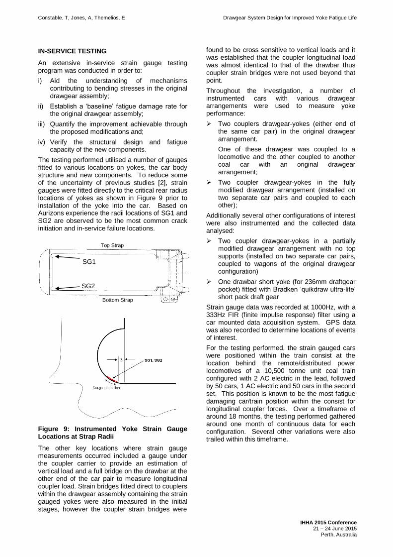
The testing performed utilised a number of gauges fitted to various locations on yokes, the car body structure and new components. To reduce some of the uncertainty of previous studies [2], strain gauges were fitted directly to the critical rear radius locations of yokes as shown in Figure 9 prior to installation of the yoke into the car. Based on Aurizons experience the radii locations of SG1 and SG2 are observed to be the most common crack initiation and in-service failure locations.
Figure 9: Instrumented Yoke Strain Gauge Locations at Strap Radii
The other key locations where strain gauge measurements occurred included a gauge under the coupler carrier to provide an estimation of vertical load and a full bridge on the drawbar at the other end of the car pair to measure longitudinal coupler load. Strain bridges fitted direct to couplers within the drawgear assembly containing the strain gauged yokes were also measured in the initial stages, however the coupler strain bridges were
found to be cross sensitive to vertical loads and it was established that the coupler longitudinal load was almost identical to that of the drawbar thus coupler strain bridges were not used beyond that point.
Throughout the investigation, a number of instrumented cars with various drawgear arrangements were used to measure yoke performance:
Two couplers drawgear-yokes (either end of the same car pair) in the original drawgear arrangement.
One of these drawgear was coupled to a locomotive and the other coupled to another coal car with an original drawgear arrangement;
Two coupler drawgear-yokes in the fully modified drawgear arrangement (installed on two separate car pairs and coupled to each other);
Additionally several other configurations of interest were also instrumented and the collected data analysed:
Two coupler drawgear-yokes in a partially modified drawgear arrangement with no top supports (installed on two separate car pairs, coupled to wagons of the original drawgear configuration)
One drawbar short yoke (for 236mm draftgear pocket) fitted with Bradken ‘quikdraw ultra-lite’ short pack draft gear
Strain gauge data was recorded at 1000Hz, with a 333Hz FIR (finite impulse response) filter using a car mounted data acquisition system. GPS data was also recorded to determine locations of events of interest.
For the testing performed, the strain gauged cars were positioned within the train consist at the location behind the remote/distributed power locomotives of a 10,500 tonne unit coal train configured with 2 AC electric in the lead, followed by 50 cars, 1 AC electric and 50 cars in the second set. This position is known to be the most fatigue damaging car/train position within the consist for longitudinal coupler forces. Over a timeframe of around 18 months, the testing performed gathered around one month of continuous data for each configuration. Several other variations were also trailed within this timeframe.
SG1
SG2
Top Strap
Bottom Strap
Constable. T, Jones, A, Themelios. E Drawgear System Design for Improved Yoke Fatigue Life
IHHA 2015 Conference 21 – 24 June 2015 Perth, Australia
DATA ANALYSIS
Data was analysed for 24 mine-port return trips for the as-built and 26 trips for the modified drawgear configuration, representing around 20,000km of data for each configuration. The data from all trips passed through a low pass filter, which attenuated frequencies above 7.5 Hz. The rainflow-counting method was used in order to break down the spectrum of varying load/stress recorded into equivalent numbers of load/stress ranges of different magnitudes for the measured drawbar force and yoke strain gauges. The number of cycles were normalised to 1000km to compare between trips i.e.:
No. of Cycles + Trip Distance (km) x 1000 (km) In order to establish a measure of fatigue damage it is assumed that the damage-stress relationship is non-linear, rather (based on typical S-N curves for most steels) it is assumed that the damage-stress relationship is in fact cubic, therefore: Σ∞
damage index ∝ Sr3
where Sr = cyclic stress range A damage rate based on force was used to normalise the measured yoke fatigue against the applied coupler loading for a given trip.
damage index ∝ Fr3
where Fr = cyclic stress range As yokes were noted has having a range of residual stress levels, mean stress effects were neglected and the relative fatigue damage estimated via expressions of the form: k
Cumulative damage index = ∑ ni x Fri3 i =1
where Fri = cyclic force range and
ni = number of cycles
Explicit calculation of fatigue life for these locations was not of the highest importance for the current assessment, as the basis of assessment was performed on a comparative basis with the original rate of damage. As such the results are expressed as a damage rate rather than specific fatigue life.
STRAIN GAUGE TESTING RESULTS
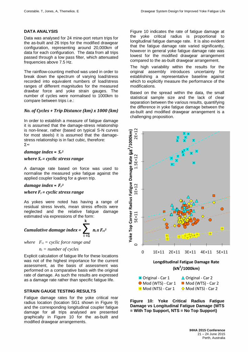
Fatigue damage rates for the yoke critical rear radius location (location SG1 shown in Figure 9) and the corresponding longitudinal coupler fatigue damage for all trips analysed are presented graphically in Figure 10 for the as-built and modified drawgear arrangements.
Figure 10 indicates the rate of fatigue damage at the yoke critical radius is proportional to longitudinal fatigue damage rate. It is also evident that the fatigue damage rate varied significantly, however in general yoke fatigue damage rate was lowest for the modified drawgear arrangement compared to the as-built drawgear arrangement.
The high variability within the results for the original assembly introduces uncertainty for establishing a representative baseline against which to explicitly measure the performance of the modifications.
Based on the spread within the data, the small statistical sample size and the lack of clear separation between the various results, quantifying the difference in yoke fatigue damage between the as-built and modified drawgear arrangement is a challenging proposition.
05
E+1
11
E+1
21
.5E+
12
2E+
12
0 1E+11 2E+11 3E+11 4E+11 5E+11
Longditudinal Fatigue Damage Rate
(kN3/1000km)
Yo
ke T
op
Co
rne
r R
adiu
s Fa
tigu
e D
amag
e R
ate
( me3 /1
00
0km
)
Original - Car 1 Original - Car 2Mod (WTS) - Car 1 Mod (WTS) - Car 2Mod (NTS) - Car 1 Mod (NTS) - Car 2
b
Figure 10: Yoke Critical Radius Fatigue Damage vs Longitudinal Fatigue Damage (WTS = With Top Support, NTS = No Top Support)
Constable. T, Jones, A, Themelios. E Drawgear System Design for Improved Yoke Fatigue Life
IHHA 2015 Conference 21 – 24 June 2015 Perth, Australia
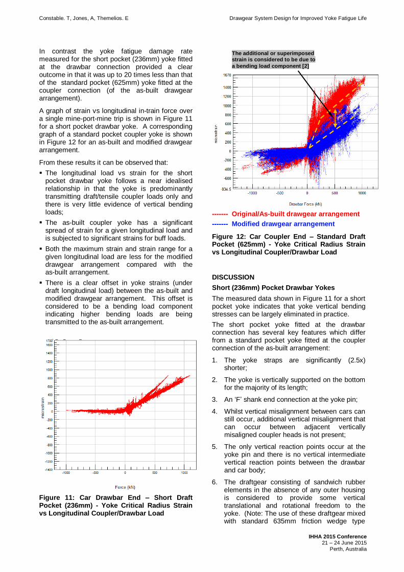
In contrast the yoke fatigue damage rate measured for the short pocket (236mm) yoke fitted at the drawbar connection provided a clear outcome in that it was up to 20 times less than that of the standard pocket (625mm) yoke fitted at the coupler connection (of the as-built drawgear arrangement).
A graph of strain vs longitudinal in-train force over a single mine-port-mine trip is shown in Figure 11 for a short pocket drawbar yoke. A corresponding graph of a standard pocket coupler yoke is shown in Figure 12 for an as-built and modified drawgear arrangement.
From these results it can be observed that:
The longitudinal load vs strain for the short pocket drawbar yoke follows a near idealised relationship in that the yoke is predominantly transmitting draft/tensile coupler loads only and there is very little evidence of vertical bending loads;
The as-built coupler yoke has a significant spread of strain for a given longitudinal load and is subjected to significant strains for buff loads.
Both the maximum strain and strain range for a given longitudinal load are less for the modified drawgear arrangement compared with the as-built arrangement.
There is a clear offset in yoke strains (under draft longitudinal load) between the as-built and modified drawgear arrangement. This offset is considered to be a bending load component indicating higher bending loads are being transmitted to the as-built arrangement.
Figure 11: Car Drawbar End – Short Draft Pocket (236mm) - Yoke Critical Radius Strain vs Longitudinal Coupler/Drawbar Load
------- Original/As-built drawgear arrangement
------- Modified drawgear arrangement
Figure 12: Car Coupler End – Standard Draft Pocket (625mm) - Yoke Critical Radius Strain vs Longitudinal Coupler/Drawbar Load
DISCUSSION
Short (236mm) Pocket Drawbar Yokes
The measured data shown in Figure 11 for a short pocket yoke indicates that yoke vertical bending stresses can be largely eliminated in practice.
The short pocket yoke fitted at the drawbar connection has several key features which differ from a standard pocket yoke fitted at the coupler connection of the as-built arrangement:
1. The yoke straps are significantly (2.5x) shorter;
2. The yoke is vertically supported on the bottom for the majority of its length;
3. An ‘F’ shank end connection at the yoke pin;
4. Whilst vertical misalignment between cars can still occur, additional vertical misalignment that can occur between adjacent vertically misaligned coupler heads is not present;
5. The only vertical reaction points occur at the yoke pin and there is no vertical intermediate vertical reaction points between the drawbar and car body;
6. The draftgear consisting of sandwich rubber elements in the absence of any outer housing is considered to provide some vertical translational and rotational freedom to the yoke. (Note: The use of these draftgear mixed with standard 635mm friction wedge type
The additional or superimposed strain is considered to be due to
a bending load component [2]
Constable. T, Jones, A, Themelios. E Drawgear System Design for Improved Yoke Fatigue Life
IHHA 2015 Conference 21 – 24 June 2015 Perth, Australia
draftgear has also been found to be beneficial with respect to reducing dynamic longitudinal coupler loads in consists [6]).
It is notable that the only failures of short drawbar yokes in this configuration within Aurizon’s operations have been associated with cast yoke components that have a particularly sharp rear radius by design and also found to be of poor casting quality. To date no failures have been associated with short pocket yokes at drawbar connections with a critical radius of 12mm or greater.
Whilst the absence of significant bending stresses at the rear radius of these yokes dramatically improves the life of the component at this critical location, it is important to realise that in the absence of bending, other locations are equally highly stressed as the rear radius and thus critical fatigue locations will also likely occur at the front of the yoke as highlighted by the stress distribution shown top in Figure 2 and [5].
Standard (625mm) Pocket Coupler Yokes
FEA simulations demonstrated that the as-built drawgear arrangement can permit vertical misalignment of the drawgear that can lead to undesirably high bending loads which can significantly affect yoke fatigue life at the critical rear radius locations. The mechanism that causes the drawgear to misalign vertically was shown to be primarily vertically upward or downward coupler loads or eccentrically applied buff longitudinal coupler loads.
FEA simulations also demonstrated that the proposed drawgear modifications shown in Figure 7 will reduce the amount drawgear vertical misalignment that is possible within the draft pocket and will thus limit the amount of bending load that can potentially be transmitted to the yoke. Hence it was expected that in general this would lead to an improvement in fatigue life.
In-service testing results (Figure 10) show that in all instances the modified drawgear arrangement demonstrated lower yoke fatigue damage rates however the extent of the reduction and distinction between the modified and as-built drawgear arrangements was not considered to be clear enough to fully quantify the effectiveness of the modifications at this stage of the in-service evaluation. There are a number of possible explanations for this:
FEA simulations indicated under draft load conditions the stresses at the critical rear radius locations are significantly influenced by coupler/vehicle height differences (i.e. longitudinal load eccentricity), whether the drawgear modifications are included or not.
Coupler/vehicle height difference between coupled vehicles was not recorded for all train
runs and therefore its influence on the results cannot be removed or explicitly accounted for at this stage.
FEA simulations indicated the proposed drawgear modifications can provide significant reductions in stress at the critical radius locations for moderate to high magnitudes of vertical loads (240kN) and eccentric buff loads (1MN & 40mm eccentricity) in particular, with little change in performance expected for draft loads.
Thus, the overall success of the drawgear modifications hinges upon the balance between improvements made for vertical and buff coupler loads (and over the range of these loads) compared to the modest change in damage rate for draft loading.
This could be quantitatively assessed through fatigue analysis of the yoke strains corresponding to draft, buff and vertical loads separately. In addition, consideration would need to be given to the difference in fatigue damage accumulated over the range of low-medium load levels compared to medium-high load levels.
FEA simulations indicated that the preload of the draft gear (when installed into the draft pocket) can affect the resistance of the drawgear to misalign vertically and therefore can affect the level of bending loads transmitted into the yoke.
Predominantly three different types of draft gear (Miner TF880, TF880Q & Crown SE) were fitted to the instrumented coal cars. The TF880Q draft gear has a fundamentally different installed preload (due to its differing stiffness characteristics) compared to the other two draft gear types hence this introduces another variable that potentially needs to be accounted for or eliminated.
The drawgear modifications being evaluated more tightly constrain the drawgear compared to the as-built arrangement and therefore help to limit yoke bending loads/stresses. However there are still small gaps (3 to 5mm) between the drawgear and draft pocket supports/spacers (so as to not impede the longitudinal action of the drawgear) that still allow some amount of vertical bending load to be transmitted to the yoke.
FEA simulations showed the yoke bending stresses are sensitive to the gaps between the drawgear and draft pocket supports/spacers. Construction accuracy across the instrumented cars is yet to be confirmed and therefore cannot be accounted for at this point.
FEA simulations of the as-built drawgear configuration indicated as the amount of wear in the coupler shank carrier increases the yoke bending loads/stresses also increase but only for vertically downward coupler loads.
Constable. T, Jones, A, Themelios. E Drawgear System Design for Improved Yoke Fatigue Life
IHHA 2015 Conference 21 – 24 June 2015 Perth, Australia
In this instance carrier wear levels or the loss of coupler carrier wear pads, a known occurrence, was not recorded.
This highlights some of the key variables to be considered when interpreting the in-service results and hence highlights the challenges of quantifying the effectiveness of the drawgear modifications.
Whilst an attempt was made to measure and document all the car variables which could influence yoke fatigue, the number of variables and the operational environment in which the testing was performed made this a challenging objective and was not always achieved to the extent which would allow interpretation of the measured results in a direct analytical/comparative way with respect to the FEA modelling. The most notable undefined variable in this regards was variability in coupler vertical height differences between coupled vehicles, which was shown by the FEA modelling to significantly influence the stresses at the rear radius locations.
Nevertheless the in-service testing results do demonstrate, at this stage of the evaluation, that the drawgear modifications provide an average improvement in yoke fatigue life compared to the original/as-built drawgear arrangement.
It is also noted that of the four instrumented cars fitted with modified drawgear arrangements, none exhibited the extent of yoke strains as the original Car 1 yoke (Figure 10), which could support the hypothesis that the drawgear modifications are successful at mitigating the more extreme yoke bending loads/stresses.
However to more conclusively assess the effectiveness of the drawgear modifications it is considered that a larger sample size would be needed that potentially includes:
Deliberate sampling over the operational range of coupled car height differences for car to car and car to locomotive couplings and coupler shank wear pad levels.
If feasible, sample during the wet season in Central Queensland where track condition is empirically known to deteriorate causing vertical vehicle dynamics to be more pronounced i.e. higher vertical components of coupler force are likely to be generated and therefore higher yoke bending loads.
Eliminate variables such a different draft gear types to remove these as potential points of difference.
Future Design Considerations
The present study has demonstrated the design of rolling stock drawgear components cannot be considered in isolation and as such need to be designed as an entire system with particular consideration given to the mechanical restraint of
the drawgear within the draft pocket and the degree of vertical rotational freedom afforded to the coupler.
The study has also highlighted the potential criticality of vertical and offset longitudinal coupler forces to yokes. As such these forces should be included in the design and analysis of yokes, but also to other drawgear components such as couplers, knuckles and also adjacent car body interfaces such as headstocks and draft gear pockets. Such design considerations are suggested, but not explicitly obvious in paragraph 3.3.2 of AAR M-215 [7].
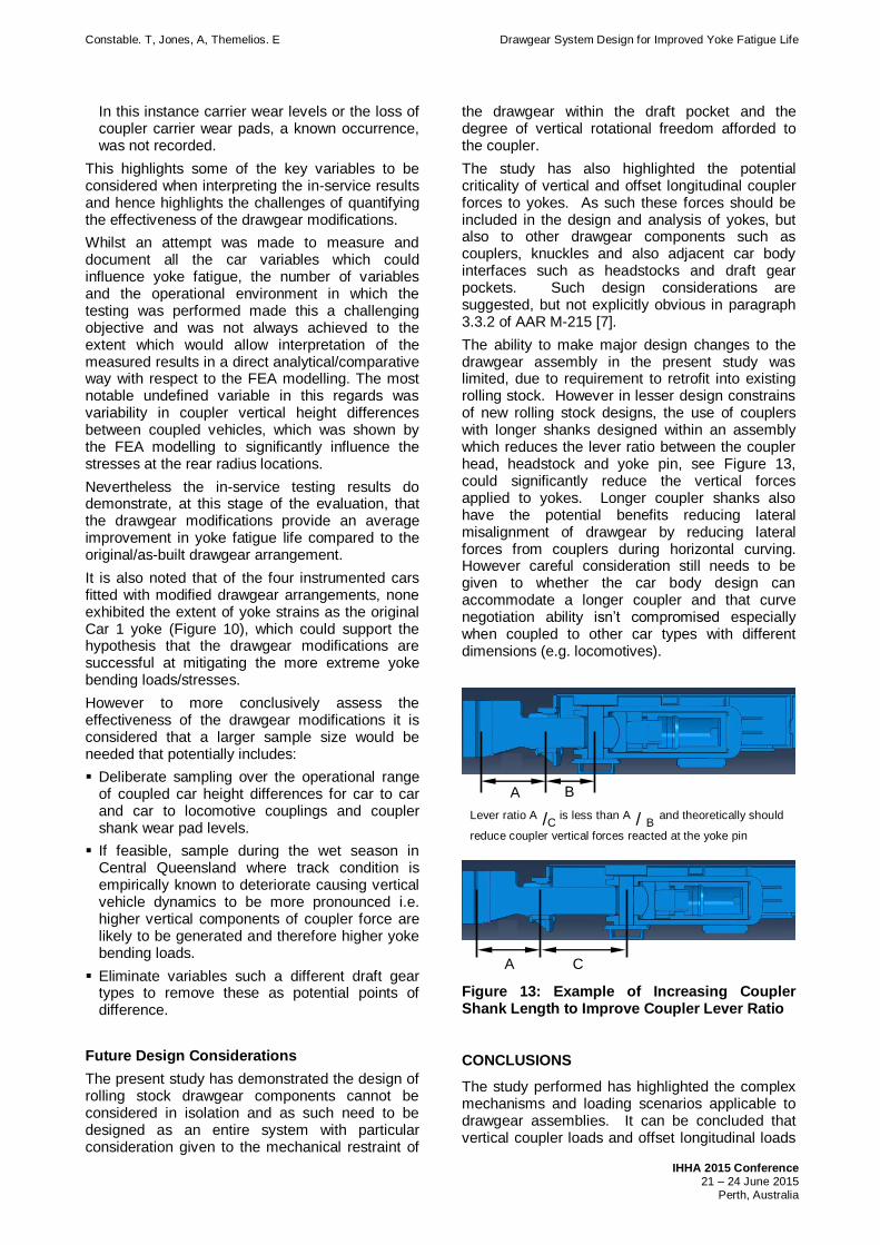
The ability to make major design changes to the drawgear assembly in the present study was limited, due to requirement to retrofit into existing rolling stock. However in lesser design constrains of new rolling stock designs, the use of couplers with longer shanks designed within an assembly which reduces the lever ratio between the coupler head, headstock and yoke pin, see Figure 13, could significantly reduce the vertical forces applied to yokes. Longer coupler shanks also have the potential benefits reducing lateral misalignment of drawgear by reducing lateral forces from couplers during horizontal curving. However careful consideration still needs to be given to whether the car body design can accommodate a longer coupler and that curve negotiation ability isn’t compromised especially when coupled to other car types with different dimensions (e.g. locomotives).
Figure 13: Example of Increasing Coupler Shank Length to Improve Coupler Lever Ratio
CONCLUSIONS
The study performed has highlighted the complex mechanisms and loading scenarios applicable to drawgear assemblies. It can be concluded that vertical coupler loads and offset longitudinal loads
A B
A C
Lever ratio A /C is less than A / B and theoretically should
reduce coupler vertical forces reacted at the yoke pin

Constable. T, Jones, A, Themelios. E Drawgear System Design for Improved Yoke Fatigue Life
IHHA 2015 Conference 21 – 24 June 2015 Perth, Australia
from coupler height mismatch have the potential to contribute significantly to drawgear component and car body stresses and as such should be considered in the design process for these components.
For coupler drawgear the fatigue damage rate accumulation at the critical rear radius location is dependent on the mechanical design of the drawgear assembly and in particular how the drawgear is restrained within the car draft pocket (i.e. the location of the restraints and actual clearances provided to the drawgear).
Specific to the drawgear geometry of the present study it is concluded that the greater vertical rotational freedom offered by ‘F’ shank couplers, together with vertical support of the yoke at the coupler pin reduce the accelerated rate of fatigue accumulated by the rear radius of yoke compared to the as-built configuration with a bushed shank coupler.
However whilst a distinct improvement in performance is noted for the modified drawgear arrangement the relationship between critical radius stress vs longitudinal load is still considerably non-idealised, suggesting that further design improvements may be possible.
The particular drawgear configuration used by Aurizon at the drawbar connection with short 236mm yokes provides an efficient mechanical solution which effectively controls the fatigue damage rate within yokes to that expected from the idealised loading scenario. However it is considered that short pocket yokes are best suited to ‘slackless’ connections, such as drawbar connections, with regards to reducing in-train force dynamic effects.
The value of in-service strain measurement/ validation has also been emphasised by the work performed.
ACKNOLEDGEMENTS
An investigation of the scope complexity and significant in-field measurements performed in the present study requires the input and support of significant teams. The authors would like to than the following people whom contributed significantly in various capacities to the investigation performed: Joe Lister, Ross Ulmer, Jair Amaro, John Clayton, Brendon Haack, Roger Buckley, Arthur Napper.
REFERENCES
1. K.C. Arcus, J.M. Cookson, “Use of Ultrasonic Phased Array Testing for Detection of In Service Defects in Heavy Haul Railway Draft Gear”, Proc Special Technical Session IHHA, Calgary (2011)
2. J.M. Cookson, A. MacNish and M. Baartz, “Fatigue Cracking and Stresses in Yokes in Heavy Haul Service”, Proc. 10th IHHA Conference, New Delhi (2013), 691-695.
3. Effects of Coupler Height Mismatch on the Structural Integrity of Railroad Tank Car Stub Sills, DOT/FRA/ORD-01/14
4. AS/RISSB 7524 (2010), Railway Rolling Stock – Drawgear.
5. J.M. Cookson1, I Saleh and T Constable, “A New Test Method to Assess The Fatigue Performance of Yokes”, Proc. 11th IHHA Conference, Perth (2015).
6. Birkin D, Constable T, Cole C, Bosomworth C. “Reduction of low frequency linear vibrations in long heavy haul consists”. In Proc. CORE 2014, Adelaide. May 2014.
7. AAR Specification M215 “Coupling Systems”
8. A Smyth, J Reiling & S Ely, “Determination of the Stress State Developed within a Non-Cushioned Rail Yoke and the Prediction of the Theoretical Fatigue Life”, Proceedings of the Institution of Mechanical Engineers, Part F: Journal of Rail and Rapid Transit September 1, 2010 vol. 224 no. 5 455-463