improved fatigue delamination behaviour of … fatigue delamination behaviour of composite laminates...
TRANSCRIPT

Accepted Manuscript
Improved fatigue delamination behaviour of composite laminates with electro-
spun thermoplastic nanofibrous interleaves using the Central Cut-Ply method
Lode Daelemans, Sam van der Heijden, Ives De Baere, Hubert Rahier, Wim
Van Paepegem, Karen De Clerck
PII: S1359-835X(16)30431-6
DOI: http://dx.doi.org/10.1016/j.compositesa.2016.12.004
Reference: JCOMA 4509
To appear in: Composites: Part A
Received Date: 20 May 2016
Revised Date: 29 November 2016
Accepted Date: 2 December 2016
Please cite this article as: Daelemans, L., van der Heijden, S., De Baere, I., Rahier, H., Van Paepegem, W., De
Clerck, K., Improved fatigue delamination behaviour of composite laminates with electrospun thermoplastic
nanofibrous interleaves using the Central Cut-Ply method, Composites: Part A (2016), doi: http://dx.doi.org/
10.1016/j.compositesa.2016.12.004
This is a PDF file of an unedited manuscript that has been accepted for publication. As a service to our customers
we are providing this early version of the manuscript. The manuscript will undergo copyediting, typesetting, and
review of the resulting proof before it is published in its final form. Please note that during the production process
errors may be discovered which could affect the content, and all legal disclaimers that apply to the journal pertain.

1
Improved fatigue delamination behaviour of composite laminates
with electrospun thermoplastic nanofibrous interleaves using the
Central Cut-Ply method
Lode Daelemans1, Sam van der Heijden
1, Ives De Baere
2, Hubert Rahier
3, Wim Van
Paepegem2, Karen De Clerck*
1
1 Department of Textiles, Ghent University, Technologiepark-Zwijnaarde 907, B-9052 Zwijnaarde,
Belgium
2 Department of Materials Science and Engineering, Ghent University, Technologiepark-Zwijnaarde 903,
B-9052 Zwijnaarde, Belgium
3 Department Materials and Chemistry, Vrije Universiteit Brussel, Pleinlaan 2, B-1050 Brussels, Belgium
* [email protected] Tel.: +32 9 264 57 40 Fax.: +32 9 264 58 46
Abstract
Adding toughening particles to composite laminates is a common approach to increase
their delamination resistance. More recently, interleaving the laminated structures with
electrospun (thermoplastic) nanofibrous veils is shown to be a viable toughening
method. Where toughening composite laminates with nanofibrous interleaves becomes
more and more evident under static conditions, the effectiveness under fatigue loadings
has yet to be proven. This article provides insight in the nanofibre toughening
mechanisms acting under fatigue conditions. Several nanofibre types with a high
potential for toughening are considered. A substantial decrease of the delamination
propagation rate up to one order of magnitude was obtained for all tested nanofibre
types. Furthermore, two distinct zones of delamination behaviour are observed in
nanofibre interleaved laminates on exposure to cyclic loading. These insights reveal the
crucial design parameters which allow for the production of nanofibre toughened
composites with an improved fatigue life.
Keywords: A. Nanocomposites, B. Damage tolerance, B. Fatigue, E. Electrospinning

2
1. Introduction
The relatively low delamination resistance of most composite laminates remains one of
the limiting factors during their in-service life. Increasing the delamination resistance of
these materials results in higher damage resistance and improved performance and
lifetime. Hence, many methods of interlaminar toughening have been proposed and
researched over the past decades [1–12]. The more recent principle of interleaving
composite laminates with electrospun nanofibrous veils has shown to be a viable
interlaminar toughening method [13–20]. There are several advantages associated to
these veils which adds to their commercial applicability. During electrospinning,
nanofibrous veils are formed as a self-supporting non-woven membrane which can be
handled in a similar way as regular fabrics. They can also be deposited directly on
fabrics by guiding dry fabric through an electrospinning set-up [20]. Hence, the veils
can easily be placed in between the primary reinforcing plies either as standalone
membranes or as nanofibre deposited fabrics prior to composite production and there is
no change in the composite manufacturing process required. The nanoscale diameter of
the nanofibres offers relatively thin interlayers, while their macroscopic length
(continuous fibres) poses no health hazards in comparison with other nanomaterials.
The electrospinning process itself is relatively simple in design and proven to be
upscalable [22,23] making it a cost-effective nanofibre production method.
Furthermore, the electrospinning process used to obtain nanofibrous veils is applicable
to many polymer types adding to its versatility [21].
Notwithstanding the numerous expected benefits, the research into composite laminates
toughened by electrospun nanofibrous interleaves is still limited. It consists mainly of
Mode I and Mode II interlaminar fracture tests performed on interleaved laminates
3
under static conditions [14,20,24–30]. Although these experiments provide useful
information about critical parameters, toughening (micro)mechanisms and general
concerns of the delamination behaviour in nanofibre interleaved laminates under static
conditions, an analysis of the effect of nanofibrous interleaves under fatigue loadings
has not been reported in literature to date. Nevertheless, a thorough understanding of the
fatigue delamination behaviour of interleaved laminates is of major concern since
almost all composite laminate structures experience fatigue loading during their in-
service life. Furthermore, it is known that the delamination behaviour in (toughened)
composite laminates can differ substantially between static and fatigue loading [31–33].
This article gives thorough insight into the fatigue delamination behaviour of
electrospun nanofibre interleaved composite laminates. Nanofibrous veils are
electrospun from polycaprolactone (PCL), polyamide 6 (PA 6) and polyamide 6.9
(PA 6.9) since these systems have proven their effectiveness under static loading
conditions [14,27,34]. The focus is on Mode II delamination behaviour as delamination
growth during service often occurs under Mode II dominated loadings. The Central Cut-
Ply (CCP) method [35] is used to determine the crack propagation rate under cyclic
loading as this method is representative for delamination initiation encountered in
structural applications, where, for example, delaminations initiate from terminated plies,
near free edges or in tapered sections. The observed toughening micromechanisms are
linked to the results obtained from static experiments, thus providing the necessary
insights in order to design novel fatigue resistant structures.
4
2. Materials and methods
2.1. Materials
PCL (MN 80 000) and PA 6 (MW 51 000 g/mol) pellets were purchased from Sigma-
Aldrich; PA 6.9 pellets (MW 58 000 g/mol) were obtained from Scientific Polymer
Products. The polymers are dissolved for electrospinning in a mixture of 98 – 100%
purity formic acid (FA) and 98% purity acetic acid (AA), both purchased from Sigma-
Aldrich and used as received. Uniform electrospun nanofibrous veils are produced on an
in-house developed multinozzle electrospinning machine; more details can be found in
Ref. [27]. Standalone nanofibrous veils are produced with an areal density in the range
of 14 ± 0.5 g/m². The PCL, PA 6 and PA 6.9 nanofibres had diameters of 650 ± 150 nm,
195 ± 35 nm and 250 ± 30 nm respectively as measured from SEM images (Figure 1a,
1b, 1c).
2.2. Methods
The Central Cut-Ply (CCP) method is used to determine the crack propagation rate
under cyclic loading [35]. This method has several advantages compared to the
traditional End Notched Flexure (ENF) specimen design such as the use of a simple grip
fixture and easy in-situ crack growth monitoring using a clip-on extensometer.
Delamination growth in the CCP specimen design initiates from (artificially) interrupted
plies instead of an initiation film. Hence, it is much more representative for the type of
delamination initiation encountered in structural applications where delaminations
initiate for example from terminated plies, near free edges or in tapered sections. The
CCP specimen consists of a unidirectional laminated specimen in which a certain
number of plies is artificially interrupted symmetrically with respect to the laminate
midplane, see Figure 2. When subjected to a far field axial tensile load, four

5
delaminations will grow under Mode II conditions as interlaminar compression prevents
Mode I opening of the delaminations [35].
The Mode II energy release rate (ERR) associated with a single delamination can be
determined using beam theory as [35]
(1)
with load , Young’s modulus of the unidirectional material without cut plies ,
specimen width , specimen thickness and the ratio of cut plies to the total number of
plies in the specimen [35]. Equation (1) shows that the Mode II ERR is independent
of delamination length and thus remains constant during fatigue tests at constant
maximum load. The delamination growth during the fatigue tests is monitored using a
clip-on extensometer which is placed in the middle of the specimen. Furthermore, a
videocamera is used to monitor the delamination length visually and validate the
extensometer measurements. Let be the strain corresponding to the peak load in
each loading cycle during the fatigue tests, the delamination length of a single
delamination can then be expressed as [35]
(2)
Differentiation of Equation (2) results in an expression for the delamination propagation
rate which is determined by the slope of the extensometer peak strain measurements
during the fatigue tests [35]
(3)
A more detailed derivation and validation of these equations for the CCP method can be
found in Ref. [35].

6
Composite laminates are produced by vacuum assisted resin transfer moulding
(VARTM) with unidirectional E-glass plies with an areal density of 500 g/m² (UDO
ES500 manufactured by SGL group) and a high toughness epoxy/amine thermoset resin
system (EPIKOTE MGS RIMR135 and EPIKURE MGS RIMH137 supplied by
Momentive) typically used for wind turbine blades. More details on the used VARTM
process can be found in Ref. [36]. A total amount of 8 plies is used with the two middle
plies cut prior to stacking. Special care was taken to produce a straight cut along the
whole ply in order to have a sharply defined cut region in the final laminate. The
standalone nanofibrous veils, which have the same size as a reinforcing ply (300 x
300 mm²), are interleaved in the two interlaminar regions where delamination growth
will occur (Figure 1d). The manufacturer’s recommended curing cycle is used to cure
the laminates (24 hours at room temperature followed by a post-cure for 15 hours at 80
°C). The nominal thickness of the final laminates is 3 mm. The glass fibre volume
fraction (52 vol%) did not change when nanofibrous veils were interleaved as a two-
piece mould with a fixed thickness was used to produce the laminates. Furthermore, the
nanofibres had no measurable influence on the infusion process and the final quality of
the laminates. The infusion resin could easily impregnate the nanofibrous veils in the
interlayers. Visual inspection and microscopic images of the interlayers showed no dry
spots in the final laminates (transparent epoxy resin) indicating that the porosity did not
increase.
Six different laminated plates were produced: two non-interleaved (virgin), two PA 6.9
interleaved, one PA 6 interleaved and one PCL interleaved laminated plate. To validate
the CCP results, the same nanofibrous veils were also used to produce composite
laminated plates with an initiation film and nanofibrous veil in the midplane for ENF

7
experiments. The CCP and ENF specimens were cut from the respective laminates with
a water-cooled diamond cutting machine to nominal dimensions of 140 x 15 mm² and
140 x 20 mm² respectively. The edges of the specimens were polished in order to
remove any edge defects introduced by the cutting machine.
The CCP specimens were tested on an Instron 8801 servo-hydraulic machine equipped
with an Instron Dynacell load cell of 100 kN both under static and fatigue loading
conditions. Hydraulic wedge grips were used to fix the specimens and the alignment
was assured using an Instron alignment kit. An Instron clip-on dynamic extensometer
with 25 mm gauge length was used to monitor delamination growth during fatigue tests
and mounted centrally on the specimen. Tension-tension fatigue loading was applied at
a stress ratio of 0.1 and test frequency of 5 Hz (load-controlled). Depending on the
desired load level, the maximum fatigue stress was adjusted between 260 MPa and
620 MPa. Self-heating of the specimens was monitored using a FLIR T420 infrared
camera and was found to be acceptable (maximum heating up to 30 °C at the highest
load levels). The equations given in Section 2 were used to analyse the data from the
experiments. A Young’s modulus of 42 GPa was used in Equations (1)-(3) as measured
on unidirectional samples without cut plies. Quasi-static delamination tests were also
performed using the same set-up with a displacement-controlled movement of the grips
of 2 mm/min. The first significant drop in load represents the point of major
delamination and its value is used to determine the static Mode II interlaminar fracture
toughness obtained by the CCP method.
The ENF specimens were statically tested on an Instron 3369 electromechanical
machine using a load cell of 2 kN. The Beam Theory including Bending Rotations
(BTBR) described in Ref. [37] was used to determine . This method is similar to

8
the Compliance Based Beam Method (CBBM) used in previous work [14,27], but
corrects for large displacements. The loading roller was displaced at a speed of
1 mm/min. The span length was 100 mm and the ratio of initial delamination length to
half-span length was 0.7 in order to have stable delamination growth.
3. Results and discussion
3.1. Applicability and validation of the CCP method
3.1.1. Applicability to nanofibre interleaved composite laminates
Static CCP tests were performed in order to check if the increase in for nanofibre
interleaved laminates is not dependent on the testing method and is comparable to the
results obtained in the more commonly used ENF method, i.e. should be similar
to . Cui et al. [38] showed that through the thickness normal compressive stress
is present at the crack tips in CCP specimens. Such compressive stresses are known to
increase the measured Mode II interlaminar fracture toughness [39–41]. In order to
account for this effect, Cui et al. [38] proposed following correction for a glass
fibre/epoxy CCP specimen with a ratio of 2/8 cut plies:
(4)
in which is the experimentally determined nominal failure stress of the CCP
specimen. For the CCP specimens reported in this work, correcting for the interlaminar
compressive stress yielded values about 20% lower than directly computed from
Eq. (1). The results show good agreement between the values obtained in both tests
as shown in Figure 3. The most notable difference between and is
noted for the virgin laminates with a difference of approximately 15 %. This is in
agreement with the difference between both methods reported by other researchers and

9
is probably related to the simple beam theory used to derive Equation 1 [35].
Furthermore, the load-displacement curves of CCP specimens show a more pronounced
stick-slip crack growth (sudden drops in load upon crack extension) compared to the
stable crack growth obtained in the ENF tests. This indicates some stress build-up at the
crack tip in CCP specimens, which might be due to local through thickness compressive
stresses causing a local enhancement in , resulting in an overestimation of .
Although the Mode II interlaminar fracture toughness of the virgin laminates is already
relatively high, the nanofibrous interleaves result in a significant improvement up to a
toughness of approximately 3000 J/m² which is in the range of thermoplastic
composites [42]. Previous research by the authors has shown that this increase is due to
the development of so-called nanofibre bridging zones which occur when the
delamination path crosses the toughened interlaminar region [27]. Microscopic images
of tested CCP specimens show the same delamination crack path behaviour as observed
in ENF specimens: regular crossings of the interlaminar region in which nanofibre
bridging zones can develop (Figure 4). These crossings are important as they are
suggested to be the main cause of an increased interlaminar fracture toughness [43]. In
the region between the crossings, delamination progresses at the reinforcing fibre/matrix
interface (Figure 4), similar to non-interleaved (untoughened) laminates, and as such is
less affected by the electrospun nanofibres. Hence, the same nanofibre bridging
toughening mechanism occurs both in CCP and ENF specimens. Furthermore,
delamination initiation in a CCP specimen is more “natural” as it does not require an
initiation film, and is thus more closely related to the type of initiation that can be
expected in composite applications. This is advantageous for testing nanofibre
interleaved laminates since we have previously shown that the relative position of the

10
initiation film and the nanofibrous veil can artificially affect the observed interlaminar
fracture toughness resulting in IFT values that may not well represent the actual
material [27].
3.1.2. Validation of delamination growth measured by extensometer
As shown above, the CCP method is well suited to determine the Mode II interlaminar
fracture toughness of nanofibre interleaved laminates. Furthermore, the CCP method
allows for an accurate monitoring of the delamination growth during fatigue testing, as
needed to determine the fatigue delamination behaviour, from relatively simple
extensometer measurements through Equation (3). Figure 5 shows the delamination
length - as calculated by Equation (2) from the strain measurements – as a function of
the amount of loading cycles for virgin (non-interleaved) laminates at a high and a low
value of load severity . The delaminations grow linearly with the
amount of loading cycles and the slope of this curve is equal to the delamination growth
rate as defined by Equation (3). A linear delamination growth behaviour is
observed for all virgin specimens, independent of the applied load severity. In addition,
a visual observation of the delamination front also enables the calculation of the
delamination growth rate by measuring the delamination length after a certain amount
of loading cycles. Figure 6a reveals that the delamination growth rate determined by
Equation (3) agrees well with the growth rate determined from visual observation.
Hence, the CCP method provides the means to accurately determine the delamination
length in-situ based on relatively simple strain measurements. This is advantageous as
the Mode II delamination front is usually difficult to determine visually from the edges
of a specimen when the laminates are not translucent [44]. The delamination growth rate
11
of the virgin laminates decreases proportionally to the load ratio and the datapoints fit
well to the semi-empirical model proposed by Allegri et al.
(5)
where and are empirically derived constants [35], see Figure 6b. The datapoints in
Figure 6b were fitted to Equation (5) using a least squares regression algorithm. The
model gives a linear dependency between and on a double
logarithmic scale. Table 1 represents the fitting coefficients and a quantitative measure
for the fitting accuracy of Equation (5) using the coefficient of determination (CoD).
The semi-empirical model describes the behaviour of the virgin laminates well with a
CoD of 96.4 %.
3.2. Analysis of the fatigue behaviour of nanofibre interleaved composites
3.2.1. Delamination growth behaviour
The delamination growth behaviour during the fatigue testing of nanofibre interleaved
specimens is found to be different from that of the virgin specimens. A distinct
transition in delamination propagation rate was often observed after a few millimetres of
delamination growth in the CCP specimens. Initially, the delamination grows relatively
slowly for several millimetres at a constant rate after which the delamination growth
rate increases to values similar to those of the virgin specimens. This is schematically
represented in Figure 7. Microscopic images of the cross-section of failed CCP
specimens taken near the initiation region showed the same delamination behaviour as
observed in the static experiments, i.e. regular crossings of the nanofibre toughened
interlaminar region (Figure 4). At several millimetres away from the initiation region,
some specimens showed almost complete glass fibre/epoxy debonding with none or
very few interlaminar crossings. Hence, at these points, the delamination growth rate

12
starts to approach that of the virgin non-interleaved specimens as the amount of
interlaminar crossings is minimal. Observation of the fracture surface indicates that the
distance between two neighbouring interlaminar crossings can become smaller with
increasing delamination growth. Eventually, both crossings combine at a certain point
of delamination growth after which the delamination grows by glass fibre/epoxy
debonding without crossing the interlayer (Figure 8). This mechanism of interlaminar
crossing suppression causes the distinct delamination behaviour observed in nanofibre
interleaved specimens.
The transition from a delamination path with interlaminar crossings (Region I
delamination growth) to one without (Region II delamination growth) is not
instantaneous, but spans a certain amount of cycles and a certain amount of
delamination growth. This transition zone is associated with the disappearance of
individual interlaminar crossings. Observation of the fracture surface showed that these
crossings do not disappear at the same time (same point of delamination growth). In
addition, the transition zone is further broadened as this effect is present at each of the
four delamination interfaces
3.2.2. Effect of load severity on delamination growth behaviour
The transition from Region I to Region II delamination growth in nanofibre interleaved
specimens seems to be predominantly present at low load levels, while a constant
delamination growth rate is more often observed at high load levels (Figure 9).
Inspection of the fracture surface of failed specimens showed that the suppression
mechanism is still present at high load levels, but takes place after a longer length of
delamination. As such, the transition from Region I to Region II delamination growth
was not always visible on the delamination growth data as it happened at delamination
13
lengths higher than the maximum measurable delamination length (using an
extensometer of 25 mm travel).
Particularly at the lower load levels, the driving force for the suppression of interlaminar
crossings seems to be high, which results in complete glass fibre/epoxy interfacial
failure without crossings after several millimetres. As the amount of delamination
growth per cycle decreases substantially at lower load severities, the delamination has
more time (i.e. more cycles) to realign itself in a more energetic favourable position
outside of the toughened interlayer (i.e. at the glass fibre/epoxy interface) after only a
few millimetres. Furthermore, the plasticity of the epoxy matrix increases at lower
strain rates [45] which adds to the driving force for the suppression of interlaminar
crossings at low load severities as the increased plasticity also causes an increased
matrix toughness.
The interlaminar crossing suppression was also observed on the fracture surfaces of
CCP and ENF specimens tested under static conditions, but there it took several
centimetres before all the interlaminar crossings have disappeared. Hence, the
mechanism of interlaminar crossing suppression seems to always be present in
nanofibre interleaved specimens, but the length at which all the crossings have
disappeared depends on the type of loading (high load severity, low load severity,
static). Furthermore, it also depends on the type of nanofibre system (Figure 9). In
general, for the same kind of loading, PCL nanofibres result in a longer Region I
delamination growth compared to PA 6.9 and PA 6 nanofibres.
3.2.3. Improved fatigue delamination resistance
The delamination growth rate as a function of the load severity for the nanofibre
interleaved laminates is given in Figure 10. The plotted delamination growth rates were

14
calculated from strain measurements in Region I. All nanofibre interleaved specimens
showed an overall decrease in as compared to the virgin (non-interleaved)
specimens, indicating an improved delamination resistance under fatigue loading.
Improvements in delamination growth rate up to 15 times compared to the virgin
material were obtained for individual specimens. It is worth noting that the PCL
nanofibre interleaved specimens performed best over the range of load severities tested.
Furthermore, the delamination behaviour of the nanofibre interleaved laminates is well
described by the semi-empirical model of Equation (5) with CoD values between 90 -
95% (Table 1). As described in Section 3.1.1., the improved delamination resistance can
be associated with the formation of nanofibre bridging zones in interlaminar crossings.
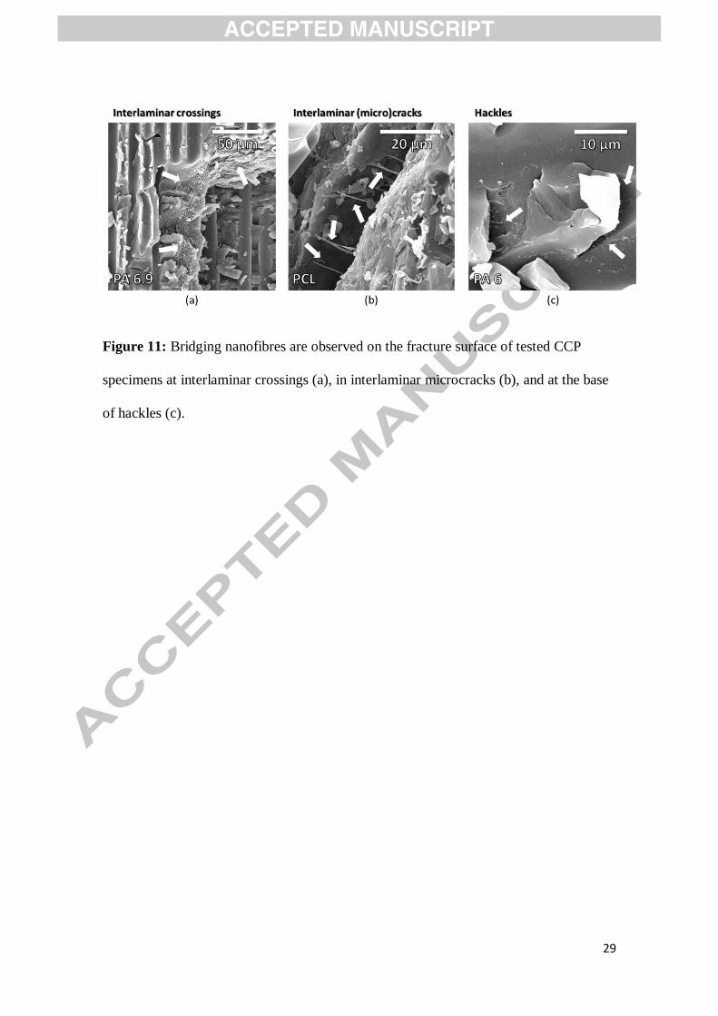
Analysis of the fracture surface of tested CCP specimens showed that these nanofibre
bridging zones also form under fatigue loading conditions, see Figure 11. They mainly
develop at interlaminar crossings where the delamination causes a relatively large zone
of interlaminar failure, but also occur at other interlaminar (micro)cracks, for example
during hackle formation (tensile microcracking at 45° relative to the delamination
plane).
A more detailed SEM analysis of the nanofibre bridging zones in interlaminar crossings
is represented in Figure 12. The electrospun nanofibres protrude from the epoxy resin
and show a high degree of plastic deformation (Figure 12a and Figure 12c). Their
morphology is typical for static tensile failure of (thermoplastic) fibres with a clearly
defined necked region resulting in a tip-like fibre end. A similar nanofibre morphology
is observed on statically tested CCP specimens. Crazing is observed at the interface
between PCL nanofibres and epoxy indicative of a good adhesion between both
polymers (Figure 12b) as reported earlier [43]. In the case of polyamide nanofibres, the

15
interface is mainly governed by relatively weak Van der Waals forces or hydrogen
bonds resulting in a relatively weak PA-epoxy interface [46]. Indeed, the PA nanofibres
occasionally debond from the epoxy resin without much deformation, resulting in
smooth nanofibre imprints in the epoxy (Figure 12d). This peeling mechanism most
likely results in a lower energy uptake than if the nanofibres would plastically deform.
Hence, the difference in interface quality between PCL-epoxy and PA-epoxy can
explain why PCL nanofibres outperform the PA nanofibres in the fatigue tests.
Conclusion
This article describes the Mode II delamination behaviour of composite laminates
toughened with electrospun nanofibrous interleaves under fatigue loading. The Central
Cut-Ply method is used as it allows for a natural crack initiation into the nanofibre
toughened interlayers similar to the initiation mechanism expected during service. The
CCP method is found to give similar results for the Mode II interlaminar fracture
toughness as the more commonly used ENF method. The CCP method however allows
for an accurate monitoring of the delamination growth during fatigue testing from
relatively simple extensometer measurements. This was validated by comparing the
delamination growth rate obtained by strain measurements with the actual delamination
growth rate obtained from visual observation of the delamination front.
Static experiments showed that the increase in interlaminar fracture toughness is
associated with the development of nanofibre bridging zones at interlaminar crossings.
Under fatigue loading, the same mechanism of nanofibre bridging at interlaminar
crossings is observed. This results in a substantial decrease in delamination growth rate
up to one order of magnitude, and thus, an improved delamination behaviour under
fatigue conditions of nanofibre interleaved composite laminates. A distinct fatigue

16
delamination behaviour is observed for nanofibre interleaved laminates: depending on
the applied load severity, there is a tendency for suppression of interlaminar crossings
after a certain amount of delamination growth. The delamination growth of nanofibre
interleaved specimens thus exhibits three regions during fatigue testing. Initially
(Region I), the delamination propagation rate remains relatively constant and is smaller
than the rate of the non-interleaved material. As more and more interlaminar crossings
disappear, the delamination growth rapidly increases and the delamination growth rate
of the nanofibre interleaved specimens approaches the rate of the non-interleaved
material when no interlaminar crossings remain (Region II). Both regions are separated
by a transition zone in which the interlaminar crossings combine and disappear.
Especially at low load severities, the driving force for this suppression mechanism is
found to be high.
All three nanofibre types tested, i.e. PA 6, PA 6.9 and PCL, result in improved fatigue
delamination resistance, and the PCL interleaved laminates have the best performance
over the range of load severities tested. Analysis of the fracture surfaces with SEM
shows bridging nanofibres protruding from the epoxy matrix. Upon crack extension,
these nanofibres will strain, yield and fail resulting in a significant amount of absorbed
energy. Despite the fact that the CCP specimens are subjected to fatigue loading, the
protruding nanofibres failure mode is similar to that found for (quasi-)static tensile
failure of polymer fibres with a necked region resulting in a tip-like fibre end after
failure.
The results obtained in this work indicate that nanofibrous veils are suitable as an
interlaminar toughener under both static and fatigue (Mode II) loading conditions as
they improve the delamination resistance considerably. Furthermore, the veils are easily

17
integrated in composite laminates without any changes to the composite production
process or the quality of the final laminates. As such, they are a viable interlaminar
toughening material for high-end and demanding composite applications.
4. Acknowledgements
Financial support from the Agency for Innovation by Science and Technology of
Flanders (IWT) and the Special Research Fund (BOF) Ghent University is gratefully
acknowledged. Results in this paper were obtained within the framework of the IWT
Strategic Basic Research Grant 141344 and the BOF 13/24J/020 project.
5. References
[1] Quaresimin M, Schulte K, Zappalorto M, Chandrasekaran S. Toughening
mechanisms in polymer nanocomposites: From experiments to modelling.
Compos Sci Technol 2015;123:187–204.
doi:10.1016/j.compscitech.2015.11.027.
[2] Manjunatha CM, Taylor AC, Kinloch AJ, Sprenger S. The tensile fatigue
behaviour of a silica nanoparticle-modified glass fibre reinforced epoxy
composite. Compos Sci Technol 2010;70:193–9.
doi:10.1016/j.compscitech.2009.10.012.
[3] Khan SU, Iqbal K, Munir A, Kim J-K. Quasi-static and impact fracture behaviors
of CFRPs with nanoclay-filled epoxy matrix. Compos Part A Appl Sci Manuf
2011;42:253–64. doi:10.1016/j.compositesa.2010.11.011.
[4] Wong DWY, Lin L, McGrail PT, Peijs T, Hogg PJ. Improved fracture toughness
of carbon fibre/epoxy composite laminates using dissolvable thermoplastic fibres.
Compos Part A Appl Sci Manuf 2010;41:759–67.
doi:10.1016/j.compositesa.2010.02.008.
[5] Sohn M-S, Hu X-Z. Mode II delamination toughness of carbon-fibre/epoxy
composites with chopped Kevlar fibre reinforcement. Compos Sci Technol
1994;52:439–48. doi:10.1016/0266-3538(94)90179-1.
[6] Kuwata M, Hogg PJ. Interlaminar toughness of interleaved CFRP using non-
woven veils: Part 2. Mode-II testing. Compos Part A Appl Sci Manuf
2011;42:1560–70. doi:10.1016/j.compositesa.2011.07.017.
[7] Hogg PJ. Toughening of thermosetting composites with thermoplastic fibres.
Mater Sci Eng A 2005;412:97–103. doi:10.1016/j.msea.2005.08.028.
[8] Ramirez VA, Hogg PJ, Sampson WW. The influence of the nonwoven veil
architectures on interlaminar fracture toughness of interleaved composites.
Compos Sci Technol 2015;110:103–10. doi:10.1016/j.compscitech.2015.01.016.

18
[9] Yasaee M, Bond IP, Trask RS, Greenhalgh ES. Damage control using discrete
thermoplastic film inserts. Compos Part A Appl Sci Manuf 2012;43:978–89.
doi:10.1016/j.compositesa.2012.01.011.
[10] Tsotsis TK. Interlayer toughening of composite materials. Polym Compos
2009;30:70–86. doi:10.1002/pc.20535.
[11] Yokozeki T, Iwahori Y, Ishibashi M, Yanagisawa T, Imai K, Arai M, et al.
Fracture toughness improvement of CFRP laminates by dispersion of cup-stacked
carbon nanotubes. Compos Sci Technol 2009;69:2268–73.
doi:10.1016/j.compscitech.2008.12.017.
[12] Sato N, Hojo M, Nishikawa M. Intralaminar fatigue crack growth properties of
conventional and interlayer toughened CFRP laminate under mode I loading.
Compos Part A Appl Sci Manuf 2015;68:202–11.
doi:10.1016/j.compositesa.2014.09.031.
[13] Dzenis Y. Structural nanocomposites. Science (80- ) 2008;319:419–20.
doi:10.1126/science.1151434.
[14] Daelemans L, van der Heijden S, De Baere I, Rahier H, Van Paepegem W, De
Clerck K. Using aligned nanofibres for identifying the toughening
micromechanisms in nanofibre interleaved laminates. Compos Sci Technol
2015;124:17–26. doi:10.1016/j.compscitech.2015.11.021.
[15] Zhang H, Bharti A, Li Z, Du S, Bilotti E, Peijs T. Localized toughening of
carbon/epoxy laminates using dissolvable thermoplastic interleaves and
electrospun fibres. Compos Part A Appl Sci Manuf 2015;79:116–26.
doi:10.1016/j.compositesa.2015.09.024.
[16] Bilge K, Ozden-Yenigun E, Simsek E, Menceloglu YZ, Papila M. Structural
composites hybridized with epoxy compatible polymer/MWCNT nanofibrous
interlayers. Compos Sci Technol 2012;72:1639–45.
doi:10.1016/j.compscitech.2012.07.005.
[17] Wu X-F, Rahman A, Zhou Z, Pelot DD, Sinha-Ray S, Chen B, et al.
Electrospinning core-shell nanofibers for interfacial toughening and self-healing
of carbon-fiber/epoxy composites. J Appl Polym Sci 2013;129:1383–93.
doi:10.1002/app.38838.
[18] Huang Z-M, Zhang Y-Z, Kotaki M, Ramakrishna S. A review on polymer
nanofibers by electrospinning and their applications in nanocomposites. Compos
Sci Technol 2003;63:2223–53. doi:10.1016/S0266-3538(03)00178-7.
[19] Kim J, Reneker DH. Mechanical properties of composites using ultrafine
electrospun fibers. Polym Compos 1999;20:124–31. doi:10.1002/pc.10340.
[20] van der Heijden S, Daelemans L, De Schoenmaker B, De Baere I, Rahier H, Van
Paepegem W, et al. Interlaminar toughening of resin transfer moulded glass fibre
epoxy laminates by polycaprolactone electrospun nanofibres. Compos Sci
Technol 2014;104:66–73. doi:10.1016/j.compscitech.2014.09.005.
[21] Greiner A, Wendorff JH. Electrospinning: a fascinating method for the
preparation of ultrathin fibers. Angew Chem Int Ed Engl 2007;46:5670–703.

19
doi:10.1002/anie.200604646.
[22] Persano L, Camposeo A, Tekmen C, Pisignano D. Industrial Upscaling of
Electrospinning and Applications of Polymer Nanofibers: A Review. Macromol
Mater Eng 2013;298:504–20. doi:10.1002/mame.201200290.
[23] Agarwal S, Burgard M, Greiner A, Wendorff J. Electrospinning: A Practical
Guide to Nanofibers. 2016.
[24] Hamer S, Leibovich H, Green A, Avrahami R, Zussman E, Siegmann A, et al.
Mode I and Mode II fracture energy of MWCNT reinforced nanofibrilmats
interleaved carbon/epoxy laminates. Compos Sci Technol 2014;90:48–56.
doi:10.1016/j.compscitech.2013.10.013.
[25] Beckermann GW, Pickering KL. Mode I and Mode II interlaminar fracture
toughness of composite laminates interleaved with electrospun nanofibre veils.
Compos Part A Appl Sci Manuf 2015;72:11–21.
doi:10.1016/j.compositesa.2015.01.028.
[26] Nash NH, Ray D, Young TM, Stanley WF. The influence of hydrothermal
conditioning on the Mode-I, thermal and flexural properties of
Carbon/Benzoxazine composites with a thermoplastic toughening interlayer.
Compos Part A Appl Sci Manuf 2015;76:135–44.
doi:10.1016/j.compositesa.2015.04.023.
[27] Daelemans L, van der Heijden S, De Baere I, Rahier H, Van Paepegem W, De
Clerck K. Nanofibre bridging as a toughening mechanism in carbon/epoxy
composite laminates interleaved with electrospun polyamide nanofibrous veils.
Compos Sci Technol 2015;117:244–56. doi:10.1016/j.compscitech.2015.06.021.
[28] Zhang J, Lin T, Wang X. Electrospun nanofibre toughened carbon/epoxy
composites: Effects of polyetherketone cardo (PEK-C) nanofibre diameter and
interlayer thickness. Compos Sci Technol 2010;70:1660–6.
doi:10.1016/j.compscitech.2010.06.019.
[29] Li G, Li P, Zhang C, Yu Y, Liu H, Zhang S, et al. Inhomogeneous toughening of
carbon fiber/epoxy composite using electrospun polysulfone nanofibrous
membranes by in situ phase separation. Compos Sci Technol 2008;68:987–94.
doi:10.1016/j.compscitech.2007.07.010.
[30] Magniez K, Chaffraix T, Fox B. Toughening of a Carbon-Fibre Composite Using
Electrospun Poly(Hydroxyether of Bisphenol A) Nanofibrous Membranes
Through Inverse Phase Separation and Inter-Domain Etherification. Materials
(Basel) 2011;4:1967–84. doi:10.3390/ma4111967.
[31] Hojo M, Ando T, Tanaka M, Adachi T, Ochiai S, Endo Y. Modes I and II
interlaminar fracture toughness and fatigue delamination of CF/epoxy laminates
with self-same epoxy interleaf. Int J Fatigue 2006;28:1154–65.
doi:10.1016/j.ijfatigue.2006.02.004.
[32] Hojo M, Matsuda S, Tanaka M, Ochiai S, Murakami A. Mode I delamination
fatigue properties of interlayer-toughened CF/epoxy laminates. Compos Sci
Technol 2006;66:665–75. doi:10.1016/j.compscitech.2005.07.038.

20
[33] Knoll JB, Riecken BT, Kosmann N, Chandrasekaran S, Schulte K, Fiedler B. The
effect of carbon nanoparticles on the fatigue performance of carbon fibre
reinforced epoxy. Compos Part A Appl Sci Manuf 2014;67:233–40.
doi:10.1016/j.compositesa.2014.08.022.
[34] van der Heijden S, Daelemans L, De Schoenmaker B, De Baere I, Rahier H, Van
Paepegem W, et al. Interlaminar toughening of resin transfer moulded glass fibre
epoxy laminates by polycaprolactone electrospun nanofibres. Compos Sci
Technol 2014;Accepted.
[35] Allegri G, Jones MI, Wisnom MR, Hallett SR. A new semi-empirical model for
stress ratio effect on mode II fatigue delamination growth. Compos Part A Appl
Sci Manuf 2011;42:733–40. doi:10.1016/j.compositesa.2011.02.013.
[36] Daelemans L, van der Heijden S, De Baere I, Muhammad I, Van Paepegem W,
Rahier H, et al. Bisphenol A based polyester binder as an effective interlaminar
toughener. Compos Part B Eng 2015;80:145–53.
doi:10.1016/j.compositesb.2015.05.044.
[37] Arrese A, Carbajal N, Vargas G, Mujika F. A new method for determining mode
II R-curve by the End-Notched Flexure test. Eng Fract Mech 2010;77:51–70.
doi:10.1016/j.engfracmech.2009.09.008.
[38] Weicheng Cui W, Wisnom MR, Jones M. An Experimental and Analytical Study
of Delamination of Unidirectional Specimens with Cut Central Plies. J Reinf
Plast Compos 1994;13:722–39. doi:10.1177/073168449401300804.
[39] Bing Q, Sun CT. Effect of compressive transverse normal stress on mode II
fracture toughness in polymeric composites. Int J Fract 2007;145:89–97.
doi:10.1007/s10704-007-9103-4.
[40] Johnson W, Masters J, Cui W, Wisnom M, Jones M. Effect of Through
Thickness Tensile and Compressive Stresses on Delamination Propagation
Fracture Energy. J Compos Technol Res 1994;16:329. doi:10.1520/CTR10593J.
[41] Li X, Hallett SR, Wisnom MR. Predicting the effect of through-thickness
compressive stress on delamination using interface elements. Compos Part A
Appl Sci Manuf 2008;39:218–30. doi:10.1016/j.compositesa.2007.11.005.
[42] De Baere I, Jacques S, Van Paepegem W, Degrieck J. Study of the Mode I and
Mode II interlaminar behaviour of a carbon fabric reinforced thermoplastic.
Polym Test 2012;31:322–32. doi:10.1016/j.polymertesting.2011.12.009.
[43] Daelemans L, van der Heijden S, De Baere I, Rahier H, Van Paepegem W, De
Clerck K. Damage resistant composites using electrospun nanofibers: a
multiscale analysis of the toughening mechanisms. ACS Appl Mater Interfaces
2016. doi:10.1021/acsami.6b02247.
[44] Blackman BRK, Kinloch AJ, Paraschi M. The determination of the mode II
adhesive fracture resistance, GIIC, of structural adhesive joints: an effective
crack length approach. Eng Fract Mech 2005;72:877–97.
doi:10.1016/j.engfracmech.2004.08.007.
[45] Allaer K, De Baere I, Van Paepegem W, Degrieck J. Direct fracture toughness

21
determination of a ductile epoxy polymer from digital image correlation
measurements on a single edge notched bending sample. Polym Test
2015;42:199–207. doi:10.1016/j.polymertesting.2015.01.014.
[46] De Schoenmaker B, van der Heijden S, Moorkens S, Rahier H, van Assche G, De
Clerck K. Effect of nanofibres on the curing characteristics of an epoxy matrix.
Compos Sci Technol 2013;79:35–41. doi:10.1016/j.compscitech.2013.02.009.
Figure 1: SEM images of electrospun PCL (a), PA 6 (b) and PA 6.9 (c) nanofibres. The
nanofibrous veils are subsequently interleaved at the delamination interfaces near the
cut-ply region (d).

22
Figure 2: Central cut-ply specimen design. Four delaminations emanate under Mode II
loading conditions from the interrupted plies due to far field axial tensile loading. The
delamination growth is monitored in-situ by an extensometer and a videocamera.

23
Figure 3: Nominal axial stress versus displacement curves for representative CCP
specimens show that increases upon interleaving the laminates with nanofibrous
veils (a). Similar results are obtained using the standard ENF method (b) which
indicates that the applicability of the CCP method to determine the of nanofibre
interleaved laminates is good.

24
Figure 4: The delamination path in an interleaved CCP specimen shows interlaminar
crossings through the nanofibre modified interlayer. Nanofibre bridging zones mainly
develop in these crossings resulting in an improved toughness.

25
Figure 5: Delamination length in function of the amount of loading cycles at low (a)
and high (b) load severity. The delamination grows linearly with the amount of loading
cycles and the slope corresponds to the delamination growth rate.
Figure 6: Delamination growth rate in function of the applied load for virgin
(non-interleaved) specimens (each point represents an individual specimen). Good
agreement is observed between determined by strain measurements according to
Equation (3) and determined by visual observation of the delamination front (a).
The virgin material's fatigue behaviour is well approximated by the semi-empirical
model of Equation (5) (b).

26
Figure 7: The delamination growth of nanofibre interleaved CCP specimens exhibits
three regions during fatigue testing: (i) relatively constant delamination growth rate
smaller than that of the non-interleaved material (Region I), (ii) rapidly increasing
delamination growth rate due to suppression of interlaminar crossings (transition zone),
and (iii) delamination growth rate similar to that of the non-interleaved material
(Region II).

27
Figure 8: Interlaminar crossings get suppressed, resulting in complete interfacial
debonding without interlaminar crossings after a certain distance of delamination
growth. Schematic representation of cross-section views (a). Fracture surface of a failed
CCP specimen with two interlaminar crossings that disappear after 2 – 3 mm of
delamination growth (b).
Figure 9: At low load levels, nanofibre interleaved specimens show a substantial
reduction in delamination growth rate compared to the virgin specimens during
Region I delamination growth (a). At higher load levels, a constant delamination growth
rate is more often observed throughout the test (b).

28
Figure 10: The delamination growth rate decreases for laminates interleaved with
PA 6.9 (a), PA 6 (b) and PCL (c) nanofibrous veils (each point represents an individual
specimen). Overall improvements up to one order of magnitude are obtained for the
nanofibre interleaved laminates. The PCL interleaved specimens show the best
improvements over the whole load severity range considered (c).
29
Figure 11: Bridging nanofibres are observed on the fracture surface of tested CCP
specimens at interlaminar crossings (a), in interlaminar microcracks (b), and at the base
of hackles (c).

30
Figure 12: Detailed SEM images of bridging nanofibres observed on interlaminar
crossings: protruding PCL nanofibres (a), crazing observed at the PCL-epoxy interface
(b), protruding PA 6.9 nanofibres (c), and imprints left by debonded PA 6.9 nanofibres
(d).

31
Table 1: Fitting parameters and for Equation (5) and the resulting fitting accuracy
determined by the coefficient of determination (CoD).
Specimen series C
(mm/cycle)
b
(-)
CoD
(%)
Virgin (non-interleaved) 0.65 3.18 96.9
PA 6.9 interleaved 0.08 2.95 94.1
PA 6 interleaved 0.10 2.68 94.3
PCL interleaved 0.10 3.28 90.3