draft short term modifications of informal document no.1 …€¦ · · 2009-09-161 draft short...
TRANSCRIPT

1
DRAFT SHORT TERM MODIFICATIONS OF Informal document No.1ECE- R21 – INTERIOR FITTINGS - 28th session of GRSP
Agenda item 2.4
INTRODUCTION
The following pages contain the proposals that were made by the participantsof the ECE- R21 ad-hoc working group during:
1. The first meeting which was held in Madrid (03 – 04 February 2000)2. The second meeting which was held in Cologne (17 - 18 May 2000)3. The third meeting which was held in Madrid (13 – 14 September 2000)
The group reported to GRSP during the 27th session, 8-12 May 2000, about theresults of the first meeting of the ad–hoc group with an informal document.
The following draft proposal contains the results after the last meeting inMadrid. The result of this meeting can be described as follows:
1. Clarification of the scope: Vehicles of category M1 is introducedinstead “passenger cars” / Incorporation of a new item: “Power operatedwindow winders etc.”; agreed by the majority of the group
2. Extension of the definitions; agreed by the majority of the group.
3. Incorporation of a dynamic determined head impact zone; the head impactzone may be determined according to the classic static procedure defined in Annex 1 or according to a new dynamic procedure described inAnnex 8. Agreed in principle by the majority of the group.
4. Power operated window etc.The text of the Directive 74/60/EEC, last amended by Directive 2000/4/EC has been incorporated in the draft proposal. In addition the text has been modified to adapt the requirements to the technical progress.The ad- hoc group decided, that OICA should check and if necessary to improve the text of „power operated window, etc.“ because the text of the Directive including the amendments were discussed with the German vehicle manufacturers and some component manufacturers only and should be discussed with all members of OICA.
5. Leave soft material in placeThe group agreed to modify the text of the existing requirements and to introduce the head impact test procedure as a tool to find out if a softmaterial arrangement can protect hard edges or not.
TRANS/WP.29/GRSP/2000/XXpage 2
2
6. Window winder requirementsThe ad –hoc group recommend to amend a new explanatory note:Explanatory note to paragraph 5.3.2.2.:With new modern doors designs, window winders handle is sometimes surrounded by the form of the door panel, making it impossible for an occupant to touch it with his knees. It is up to the Technical Services to decide in this cases with the agreement of the manufacturer to carry out the push test as described or not.
7. Explanatory notesThe group recommend GRSP to incorporate the explanatory notes at the end of each paragraph where they belong to.If a explanatory note belongs to more than one paragraph, it should be repeated to each paragraph of the Regulation.
8. Establishing of gaps and grilles requirements (OICA)Not discussed in Madrid II; further discussion necessary.
9. Head impact test into the deployed airbag (OICA)Agreed by: F, I, E, NL, OICADisagreed by S, D, UK with serious reservationFurther discussion necessary.
To-do list:
a) Arrangement of the final discussion of paragraphs 5.1.1and annex 8
b) Further discussion and decision of gaps and grilles requirements c)Further discussion and decision of head impact test into the deployed airbag
d) Waiting on OICA result of the check of the amended “Directive”- text of “ Power operated window etc.”
The chairmans of the ECE-R21 ad- hoc group will work out an improved documenton the basis of these Informal Document No. 1, which will be presented to thesecretariat of GRSP (Mr. Ramos) in time that he can arrange an officialdocument for the next GRSP- Meeting in May 2001.The members of GRSP should do all further discussions and decisions.
Explanation of the used letters:
The existing text of ECE- R21 is written with Courier New or Courier; allmodifications are marked with fat letters.The text of the Directive 2000/4/EC (power operated window e.t.c.) is writtenin colour “ blue” and the modifications of the text of the Directive incolour “red”.Remarks, made during the Madrid II meeting are written down in “ Arial 12”letters.

3
Distr.GENERAL
TRANS/WP.29/GRSP/2000/..XX October 2000
ENGLISH ONLY
ECONOMIC COMMISSION FOR EUROPE
INLAND TRANSPORT COMMITTEE
Working Party on the Construction of Vehicles
Working Party on Passive Safety (GRSP)(Twenty- eight session, 27 - 30 November 2000,agenda item 1)
PROPOSAL FOR DRAFT AMENDMENTS TO REGULATION NO. 21(Interior fittings)
Transmitted by the Experts from Spain and Germany
Note: The text reproduced below has been prepared by the experts from Spainand Germany on the basis of several proposals which has been discussed bymembers of a special ECE R21 ad hoc working group. These group has beenestablished and agreed by GRSP during the twenty-sixth session, 29 November -3 December 1999. The members of the ad hoc working group represent experts ofE, I, D, F, NL, S, UK, USA, Japan, JASIC, CLEPA and OICA.
The following draft contains the proposals to amend, as a first target and asa short term step, the requirements of the ECE- Regulation No.21, Corrigendum1 to the 01 series of amendments to Regulation No.21 (TRANS/WP29/713 - 13April 2000 -).It is planned by GRSP, to prepare a proposal towards a second target, tocreate a global harmonised Regulation (which could be ready not before 2003)
Note: This document is distributed to the Experts on Passive Safety only.
GE.00-XXXXX

TRANS/WP.29/GRSP/2000/XXpage 4
4
PROPOSAL
Paragraph 1. Scope, amend to read:
This Regulation applies to the interior fittings of vehicles of category M1with regard to:1. 1. the interior parts of the passenger compartment other than the rear-view
mirror or mirrors;1. 2. the arrangement of the controls;1. 3. the roof or opening roof, and1. 4. the seat-back and the rear parts of seats.1. 5. Power-operated windows, roof panel and partition systems
Justification:1. Deletion of the term: "passenger cars" and incorporation of the wording"vehicles of category M1" which is well defined in the R.E.3- document andwhich corresponds with the definition of the vehicle categories used in theDirectives 70/156/EEC, Annex II, section A.2. Change of subparagraph 1.3 "the roof or sliding roof", to bring REG 21 inline with the text of the Directive 74/60/EEC, "Interior fittings"4. New subparagraph 1.5 incorporating of requirements for power operatedwindows, roof panel and partition systems-------------------------------------------------------------------------------
Paragraph 2 Definitions
Paragraph 2.1, unchanged
Paragraph 2.2. amend to read:
2. 2. "vehicle type"with regard to the interior fittings of the passenger compartment (other thanthe rear view mirrors; the arrangement of controls, the roof or sliding roof,the back rest and rear part of the seats) means power-driven vehicles vehiclesof category M1 which do not differ in such essential respects as:
2. 2. 1. the lines and constituent materials of the bodywork of the passengercompartment;
2. 2. 2. the arrangement of the controls;
2. 2. 3., (added as new paragraph)
the performance of the protective system, if the reference zone according toAnnex 8(dynamic evaluation) is chosen by the applicant.Remark: Vehicles that differ only in the performance of the protectivesystem(s) belong to the same vehicle type if they offer an equal or betterprotection for the occupants compared with the system or vehicle submitted tothe technical service responsible for conducting the approval tests.
5
Justification:1. Deletion of the phrases of paragraph 2.2 which stand in brackets, see alsoparagraph 1, Scope.2.Consequences after incorporation of the term "vehicles of category M1"and3.Introduction of new requirements in the reference zone, keeping in mind, thatit is the choice of the vehicle manufacturer as applicant to decide to use theexisting requirements (determination of reference zone, determination of thehead impact points within the head impact area, carrying out head impact teststo the instrument panel, check of radii requirements etc.)oron a voluntary base, to use the new requirements according to annex 8. In thiscase the protection performance of the vehicle equipped with a restraint systemshall show, that in case of a frontal impact (details see annex 8) no headimpact to the instrument panel occurs or a dynamic determined reference zonecan be described.
-------------------------------------------------------------------------------
Paragraph 2. 3. "reference zone", amended as:
"reference zone" means the head-impact zone as defined in annex 1 to thisRegulation. Alternatively and at the choice of the applicant and based onoccupants protected by the restraint systems installed in the vehicle type itis permitted to define a reference zone according to annex 8 of thisRegulation. In both cases the following areas are excepted:
Paragraphs 2.3.1., 2.3.2 and 2.3.3, (unchanged)
Justification:Consequences of the introduction of alternative test requirements according toannex 8.-------------------------------------------------------------------------------
Paragraphs 2.4 to 2.9 unchanged
Insert new definitions as paragraphs 2.10 to 2.17
2.10."Protective system" means interior fittings and devices intended torestrain the occupants. (see Definition paragraph 2.1. of ECE Regulation 94).
2.11. "Type of a protective system", means a category of protective deviceswhich do not differ in such essential respects as:2.11.1. their technology2.11.2. their geometry2.11.3. their constituent materials.
TRANS/WP.29/GRSP/2000/XXpage 6
6
Remark: The ad- hoc group decided, that OICA should check and if necessary toimprove the text of „power operated window, e.t.c. because the text of theDirective including the red amendments were discussed with the German vehiclemanufacturers and some component manufacturers only and should bediscussed with all members of OICA.
2.12. "Power-operated windows" means windows which are closed by powersupply of the vehicle.
2.13. "Power-operated roof-panel systems" means movable panels in thevehicle roof which are closed by power supply of the vehicle by either asliding and / or tilting motion, and which do not include convertible topsystems.
2.14. "Power-operated partition systems" means systems which divide apassenger car compartment into at least two sections and which are closedusing the power supply of the vehicle.
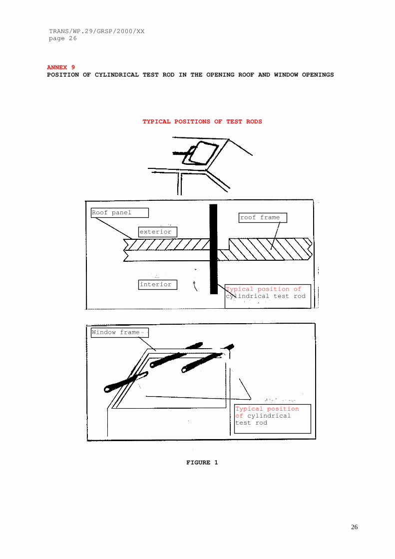
2.15. "Opening" is the maximum unobstructed aperture between the upperedge or the leading edge, depending on the closing direction, of a power-operated window or partition or roof panel and the vehicle structurewhich forms the boundary of the window, partition or roof panel, whenviewed from the interior of the vehicle or, in the case of partitionsystem, from the rear part of the passenger compartment.To measure an opening, a cylindrical test rod shall (without exertingforce) be placed through it normally perpendicular to the edge (OICA????) and perpendicular to the closing direction of the window, roofpanel or partition as shown in Annex 9,Figure 1, from the interior of thevehicle or, as applicable, from the rear part of passenger compartment.
2.16. "(Ignition) key" means a specific device that operates the locking systemof a vehicle which is built in a way that it can only be operated by thisdevice (key). This definition explicitly includes keyless entry- and/or driveauthorisation systems (OICA,?????)
2.17. inserted in Madrid II (agreed in the Cologne- meeting):
2.17. "Airbag" means a device installed to supplement safety belts andrestraint systems in power driven vehicles, i. e. systems which in the evento a severe impact effecting the vehicle automatically deploy a flexiblestructure intented to limit, by compression of the gas contained within it,the gravity of the contacts of one or more parts of an occupant of the
vehicle with the interior of the passenger compartment.

7
Justification:New definitions related to the proposed test procedure according to annex 8and the incorporation of definitions related to power- operated window, roofopening and partition systems ( printed with colour blue) and modification ofthat text ( printed in colour red) taking into account the adaptation of therequirements to the technical progress.The draft incorporates tests with airbag systems. The definition explainswhat an airbag system is. The definition is in line with ECE- Regulation 94.-----------------------------------------------------------------------------
Insertion of the explanatory notes in the text of ECE- Regulation No.21:
Justification:The below prescribed explanatory notes will be used since more than 20 yearsand should be well known by all member states. It seems helpful toincorporate these text as state of the interpretations directly in ECE-Regulation No. 21.
REMARK: The notes should be incorporated at the end of each paragraph wherethey belong to.If a explanatory note belongs to more than one paragraph, it should be repeatedto each paragraph of the Regulation.
EXPLANATORY NOTESParagraph 2. 3.The reference zone is outlined without rear view mirror. The energy-dissipation test is accomplished without the rear view mirror. The pendulumshall not impact the mirror mounting.
Paragraphs 2. 3. and 2. 3. 1.The exempted area behind the steering wheel as defined by these paragraphs isalso valid for the head impact area of the front passengers.In the case of adjustable steering wheels the zone finally exempted isreduced to the common area of the exempted zones for each of the drivingpositions which the steering wheel may assume.In the case where it is possible to choose between various steering wheelsthe exempted zone is determined by the use of the least favourablesteering wheel having the smallest diameter.
Paragraph 2. 4.The level of the instrument panel extends over the entire width of thepassenger compartment and is defined by the rearmost points of contact of avertical line with the surface of the instrument panel when the line is movedacross the width of the vehicle. where two or more points of contactoccur simultaneously, the lower point of contact shall be used to establishthe level of the instrument panel. In the case of consoles, if it is notpossible to determine the level of the instrument panel by reference to thepoints of contact of a vertical line the level of the instrument panel shallbe where a horizontal line 25. 4 mm above the "H" point of the front seatsintersects the console.
TRANS/WP.29/GRSP/2000/XXpage 8
8
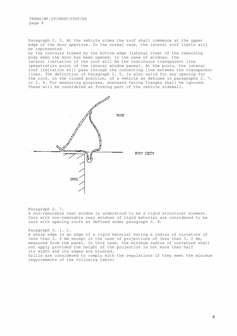
Paragraph 2. 5. At the vehicle sides the roof shall commence at the upperedge of the door aperture. In the normal case, the lateral roof limits willbe representedby the contours formed by the bottom edge (lateral view) of the remainingbody when the door has been opened. In the case of windows, thelateral limitation of the roof will be the continuous transparent line(penetration point of the lateral window panes). At the posts, the lateralroof limitation will pass through the connecting line between the transparentlines. The definition of Paragraph 2. 5. is also valid for any opening forthe roof, in the closed position, of a vehicle as defined in paragraphs 2. 7.or 2. 8. For measuring purposes, downward facing flanges shall be ignored.These will be considered as forming part of the vehicle sidewall.
Paragraph 2. 7.A non-removable rear window is understood to be a rigid structural element.Cars with non-removable rear windows of rigid material are considered to becars with opening roofs as defined under paragraph 2. 8.
Paragraph 5. 1. 1.A sharp edge is an edge of a rigid material having a radius of curvature ofless than 2. 5 mm except in the case of projections of less than 3. 2 mm,measured from the panel. In this case, the minimum radius of curvature shallnot apply provided the height of the projection is not more than halfits width and its edges are blunted.Grills are considered to comply with the regulations if they meet the minimumrequirements of the following table:

9
Paragraph 5. 1. 2.During the test, it is determined whether parts within the impact zone usedfor reinforcement may be displaced or protrude so as to increase thehazards to passengers or the severity of injuries.
Paragraph 5. 1. 3.These two concepts (level and lower edge of the instrument panel) may bedistinct. However, this point is included in paragraph 5. 1. (... above thelevel of the instrument panel ...) and, therefore is applicable only wherethese two concepts are combined. In the case where the two concepts arenot combined, i. e. where the bottom edge of the instrument panel is locatedbelow the level of the instrument panel, it will be considered underparagraph 5. 3. 2. 1. by reference to paragraph 5. 8.
Paragraph 5. 1. 4.If a pull handle or knob has a width dimension equal to or more than 50 mmand is located in a zone such that if it were less than 50 mm in widththe maximum projection would be determined using the headform measuringapparatus with annex 6, paragraph 2. , the maximum projection shall bedetermined in accordance with annex 6, paragraph 1. , i. e. by using a 165 mmdiameter sphere and determining the maximum variation in height of the"y" axis.The cross-sectional area shall be measured in a plane parallel to the surfaceon which the component is mounted.
Paragraph 5. 1. 5.Paragraphs 5. 1. 4. and 5. 1. 5. complement each other; the first sentence ofparagraph 5. 1. 5. (i. e. a force of 37. 8 daN for retraction or detachment)is applied and then paragraph 5. 1. 4. in case of retraction up to aprotrusion between 3. 2 and 9. 5 mm or, in the case of detachment, the twolast sentences of paragraph 5. 1. 5. (the cross-section area is measuredbefore the force is applied). However, if, under practical circumstancesparagraph

TRANS/WP.29/GRSP/2000/XXpage 10
10
5. 1. 4. must be applied (retraction to under 9. 5 mm and over 3. 2 mm) itcould be more convenient, at the manufacturer' s discretion, to verify thespecifications of paragraph 5. 1. 4. before applying the force of 37. 8 daNspecified in paragraph 5. 1. 5.
Paragraph 5. 1. 6.Since, in the presence of soft materials, the requirements apply only to therigid support, the projection is measured for the rigid support only.The shore hardness measurement is made on samples of the test subject itself.where, due to the condition of the material, it is impossible to carryout a hardness measurement by the shore A procedure, comparable measurementsshall be used for evaluation.Paragraph 5. 2. 1.
Foot pedals, their arms and immediate pivotal mechanism, but not thesurrounding support metal, shall be excluded from consideration.The ignition key is deemed to satisfy the requirements of this paragraph ifthe protruding part of its shank consists of a material of between 60 and80 shore A hardness and a thickness of at least 5 mm, or is covered with sucha material of 2 mm minimum thickness on all surfaces.
Paragraph 5. 2. 2.The criterion to determine whether the parking brake control can be contactedis the use of:the simulated head specified in annex 1 , if the control is located above oron the level of the instrument panel (to be tested in accordance withparagraph 5. 1. and within the impact zone);the knee specified in annex 7 if the control element is located below thelevel of the instrument panel (in this case the control lever is tested inaccordance with paragraph 5. 3. 2. 3. ).
Paragraph 5. 2. 3.The technical specifications listed in paragraph 5. 2. 3. apply also toshelves and those parts of consoles below the level of the instrument panellocated between the front seats, provided that these are located in front ofthe "H" point. If a cavity is closed it will be treated as a glovecompartment and not be subject to these specifications.

11
Paragraph 5. 2. 3. 1.The dimensions specified refer to the surface before the addition of materialof less than 50 shore A hardness (see paragraph 5. 2. 4. ).Energy-dissipating tests shall be conducted in the spirit of annex 4 .
Paragraph 5. 2. 3. 2.If a shelf becomes detached or breaks up, no dangerous features must result;this applies not only to the rim but also to other edges facing intothe passenger compartment as a result of the applied force.The strongest part of the shelf shall be considered to be adjacent to afixture. Also, "substantially distorted" shall mean that, under the effect ofthe applied force, the deflection of the shelf, measured from the initialpoint of contact with the test cylinder, must be a fold or a deformationvisible to the naked eye. Elastic deformation shall be admissible.The length of the test cylinder shall be at least 50 mm.
Paragraph 5. 3."Other parts" shall include such parts as window catches, seat belt upperanchorages and other parts located in the foot space and at the doorside, unless these parts have been treated previously or are exempted in thetext.
Paragraph 5. 3. 2.The space between the forward bulkhead and the instrument panel which islocated higher than the bottom edge of the instrument panel is notsubject to the specifications of paragraph 5. 3.
Paragraph 5. 3. 2. 1.The 3. 2 mm radius applies to all contactable components covered by paragraph5. 3. when considered in all positions of use.As exceptions, glove compartments shall be considered only in the closedposition; seat belts will normally be considered only in the fastenedposition, but any part which has a fixed stowage position shall also complywith the 3. 2 mm radius requirement in that stowed position.
Paragraph 5. 3. 2. 2.The reference surface is found by application of the device described inannex 6, paragraph 2., with a force of 2 daN. Where this is not possible,the method described in annex 6, paragraph 1., shall be used with a force of2 daN. The evaluation of dangerous projections is subject to the discretionof the authority responsible for the tests.The force of 37. 8 daN is applied even if the original projection is lessthan 35 or 25 mm, as applicable. The projection is measured under the appliedload. The horizontal, longitudinal force of 37. 8 daN is normally applied bymeans of a flat-ended ram of not more than 50 mm diameter but, wherethis is not possible, an equivalent method may be used; for instance, byremoving obstacles.
(Insertion of a new explanatory note to paragraph 5.3.2.2.):With new modern doors designs, window winders handle is sometimes surroundedby the form of the door panel, making it impossible for an occupant to touchit with his knees. It is up to the Technical Services to decide in this caseswith the agreement of the manufacturer to carry out the push test asdescribed or not.
Paragraph 5. 3. 2. 3.The furthest projecting part, in the case of a gear lever, is that part ofthe grip or knob first contacted by a vertical transverse plane moved in alongitudinal, horizontal direction. If any part of a gear lever or handbrakelies above the "H" point level, that lever will have to be considered as ifthe whole of it were above the "H" point level.

TRANS/WP.29/GRSP/2000/XXpage 12
12
Paragraph 5. 3. 4.Where the horizontal plane( s) passing through the "H" point of the lowestfront and rear seats do not coincide, then a vertical plane perpendicularto the vehicle' s longitudinal axis shall be determined, passing through thefront seat "H" point. The exempted zone will then be consideredseparately for both the front and rear passenger compartments, relative totheir respective "H" point and up to the vertical plane defined above.
Paragraph 5. 3. 4. 1.Movable sun visors shall be considered in all positions of use. The frames ofsun visors shall not be regarded as rigid supports (see para. 5. 3. 5. ).
Paragraph 5. 4.When the roof is tested to measure those protrusions and parts which can becontacted by a ball having a diameter of 165 mm, the roof lining mustbe removed. When evaluating the specified radii the proportions andproperties attributable to the materials of the roof lining shall be takenintoconsideration. The roof testing area shall extend in front of and above thetransverse plane limited by the torso reference line of the manikin placedon the rearmost seat.
Paragraph 5. 4. 2. 1.(See para. 5. 1. 1. for definition of "sharp edges").The downward projection shall be measured normal to the roof in accordancewith annex 6, paragraph 1.The width of the projecting part shall be measured at right angles to theline of the projection. In particular the rigid roof sticks or ribs shall notproject away from the inner surface of the roof more than 19 mm.
Paragraph 5. 5.Any roof ribs on opening roofs must meet paragraph 5. 4. if they arecontactable by a 165 mm diameter sphere;
Paragraphs 5. 5. 1. 2. , 5. 5. 1. 2. 1. , 5. 5. 1. 2. 2.The opening and operating devices when in a position of rest and with theroof closed must meet all of the specified conditions.
Paragraph 5. 5. 1. 2. 3.The force of 37. 8 daN is applied even if the original projection is 25 mm orless. The projection is measured under the applied load.The force of 37. 8 daN applied in the direction of impact defined in annex 4as the tangent to the trajectory of the headform is normally applied bymeans of a flat-ended ram of not more than 50 mm diameter, but where this isnot possible an equivalent method may be used; for instance, byremoving obstacles. The "position of rest" means the position of theoperating device when it is in the locked position.
Paragraph 5. 6.The rod system of convertible tops does not represent a roll-over bar.
Paragraph 5. 6. 1.
13
The top part of the windscreen frame starts above the transparent contour ofthe windscreen.
Paragraph 5. 7. 1. 1.See paragraph 5. 1. 1. for definition of "sharp edge".
Paragraph 5. 7. 1. 2.In defining the head impact zone of the back of the front seats any structurenecessary to support the seat back shall be considered as acomponent of this seat back.
Paragraph 5. 7. 1. 2. 3.The padding of the seat frame structure shall also avoid dangerous roughnessand sharp edges likely to increase the risk of serious injuries to theoccupants.
ANNEX 1DETERMINATION OF THE HEAD-IMPACT ZONEParagraph 2. 1. 1. 2.The choice between the two procedures for determining height is to be left tothe manufacturer.
Paragraph 2. 2.When determining points of contact, the length of the arm of the measuringapparatus is not changed during a particular operation. Each operationstarts from the vertical position.
Paragraph 3.The 25.4 mm dimension means the measurement from a horizontal plane passingthrough the "H" point to the horizontal tangent to the lower profileof the headform.
ANNEX 4PROCEDURE FOR TESTING ENERGY-DISSIPATING MATERIALSParagraph 1. 4.The breakage of any component during the energy-dissipation test, see Note onparagraph 5. 1. 2.
ANNEX 5PROCEDURE FOR DETERMINING THE "H" POINT AND THE ACTUAL TORSO ANGLE FORSEATING POSITIONS IN MOTOR VEHICLESParagraph 4.For determining the "H" point of any seat, other seats may be removed ifnecessary.
-----------------------------------------------------------------------------

TRANS/WP.29/GRSP/2000/XXpage 14
14
Paragraph 3,APPLICATION FOR APPROVAL, unchanged
Paragraph 4, APPROVAL, unchanged
Paragraph 5.REQUIREMENTS, amend to read:
Paragraph 5.1 amend to read:
5. 1. Forward interior parts of the passenger compartment above the level ofthe instrument panel in front of the front seat "H" Points,excluding the side doors.
5.1.1 amend to read:
New text arrangements according to the discussion in Madrid II, see 5.1.1. and5.1.7., 5.1.7.1 and 5.1.7.2.:
5. 1. 1. The reference zone defined in paragraph 2. 3. above shall not containany dangerous roughness or sharp edges likely to increase the risk of seriousinjury to the occupants.If the head impact area is determined according to annex 1, the parts referredto in paragraphs 5. 1. 2. to 5. 1. 6. below shall be deemed satisfactory ifthey comply with the requirements of those paragraphs.If the head impact area is determined according to annex 8 the requirements ofparagraph 5.1.7 apply.
Justification:The alternative test according to annex 8 is consequently added as secondpossibility and will be explained at the beginning of 5.1 in paragraph 5.1.1.
Paragraphs 5.1.2.to 5.1.5., unchanged
Paragraph 5. 1. 6., amend to read:
In the case of a projection comprising a component made of non-rigid materialof less than 50 shore A hardness mounted on a rigid support, the requirementsof paragraphs 5. 1. 4. and 5. 1. 5. shall apply only to the rigid support or itcan be demonstrated by sufficient tests according to the procedure described inannex 4 that the soft material of less than 50 shore A hardness will not be cutduring head impact tests.
Justification:In case of knobs the upper surface is often covered by a material softer than50 shore A to provide a better grip or haptic feeling to the occupants who usethe knob. Most of the designs are not dangerous even if the original radiirequirements apply not to the hard surface, but to the soft material. The testaccording to annex 4 allows to determine if the arrangement is dangerous in thesense of the Regulation.-------------------------------------------------------------------------------

15
Insert the following new paragraphs:
5.1.7. The following paragraphs shall apply:
5.1.7.1 If the protective system of the vehicle type cannot avoid headcontacts of the occupants defined in paragraph 2.1. of Annex 8 with theinstrument panel and a dynamic reference zone according to Annex 8 isdetermined the requirements of paragraphs 5.1.2. to 5.1.6. are applicableonly to the parts located in that zone.Other areas of the dashboard above the level of the instrument panel shallcontain no dangerous parts likely to increase the risk of serious injuries tothe occupants. If these parts can be contacted by a 165mm diameter sphere,they shall be at least blunted.
5.1.7.2. If the protective system of the vehicle type is able to avoid headcontacts of the occupants defined in paragraph 2.1. of Annex 8 with theinstrument panel and therefore no reference zone can be determined, therequirements of paragraphs 5.1.2. to 5.1.6. are not applicable to thisvehicle type.The dashboard above the level of instrument panel shall containno dangerous parts likely to increase the risk of serious injuries to theoccupants. Parts of the vehicle in that area which can be contacted by a165mm diameter sphere, shall be at least blunted.
Justification:Consequences of the introduction of the requirements according to Annex 8. Itis the choice of the applicant to use the well known requirements for the knobsand levers, surfaces and parts above the level of the instrument panel ( see5.1 to 5.1.6 aboveorto demonstrate the behaviour and the benefits of the restraint system. In thiscase, if no head impact occur, the requirements for knobs and levers and partscan be deleted except the general requirement of a minimum radius, that meansblunted edges in every case.-----------------------------------------------------------------------------
Paragraphs 5.2 to 5.2.3.2 unchanged
Paragraph 5.2.4 modified as:
5. 2. 4. If the items in question contain a part made of material less than 50shore A hardness when fitted to a rigid support, the above requirements, exceptfor the requirements covered by annex 4 relating to energy-absorption, shallapply only to the rigid support or it can be demonstrated by sufficient testsaccording to the procedure described in annex 4 that the soft material of lessthan 50 shore A hardness will not be cut during the head impact test. In thatcase the required radius shall apply to the soft surface only.

TRANS/WP.29/GRSP/2000/XXpage 16
16
Justification:In case of knobs the upper surface is often covered by a material softer than50 shore A to provide a better grip or haptic feeling to the occupants who usethe knob. Most of the designs are not dangerous even if the original radiirequirements apply not to the hard surface, but to the soft material. The testaccording to annex 4 allows to determine if the arrangement is dangerous in thesense of the Regulation.-------------------------------------------------------------------------------
Further requirements to “window-winder” has been deleted from the agenda ofthe ad-hoc group and shall be revised as “long term item” in the near future.
The ad –hoc group recommend to amend the Explanatory Notes as follows:Insert a new explanatory note to paragraph 5.3.2.2.:With new modern door designs, window winders handle is sometimessurrounded by the form of the door panel. It is often impossible for an occupantto touch the handle with his knees. It is up to the Technical Services to decide inthis cases with the agreement of the manufacturer to carry out the push test asdescribed or not.
-----------------------------------------------------------------------------
Paragraphs 5.3.2.3 to 5.3.4.1. unchanged
Paragraph 5.3.5 amended as:
5. 3. 5. If the parts considered above comprise a component made of material ofless than 50 shore A hardness, mounted on a rigid support, the aboverequirements shall apply only to the rigid support. or it can be demonstratedby sufficient tests according to the procedure described in annex 4 that thesoft material of less than 50 shore A hardness will not be cut during the headimpact test. In that case the required radius shall apply to the soft surfaceonly.
Justification:In case of knobs the upper surface is often covered by a material softer than50 shore A to provide a better grip or haptic feeling to the occupants who usethe knob. Most of the designs are not dangerous even if the origin radiirequirements apply not to the hard surface, but to the soft material. The testaccording to annex 4 allows to determine if the arrangement is dangerous insense of the Regulation.------------------------------------------------------------------------------
Paragraph 5.4 and subparagraphs unchanged
5.5. Vehicles with an opening roof
Paragraphs 5.5.1 to 5.5.1.2.3. unchanged
17
(The following new item is inserted)as:
Paragraph 5.5.2.In addition, power-operated roof-panel systems and their controls shall meetthe requirements of item 5.8 below.
Justification:Consequences of the introduction of requirements for power-operated window/roofopening/partition systems. It is proposed to lay down these requirements inparagraph 5.8. of the Regulation No. 21.-------------------------------------------------------------------------------
Paragraphs 5.6 to 5.7.2 unchanged
No final discussion during the Madrid II meeting !OICA will present the correct versions of ECE- Regulation 17 ( ??series ofamendments) and 25 ( ??series of amendments)D propose to add: In case of use of an approval according to REG 17 and/ or REG25 it is permitted to test the seat/head restraint system again, if furtherrequirements exist in ECE- Regulation 21 for such parts.
Paragraph 5.7.3 amend to read:
5. 7. 3. The requirements of paragraph 5. 7. shall be considered to besatisfied in the case of head restraints rear parts of seats that either arepart of a vehicle type approved under Regulation No. 17 (03 ?? series ofamendments) and in addition or are approved under Regulation No. 25 (02 ??series of amendments).(D):In case of use of an approval according to REG 17 it shall be stated inthis approval, that all aspects of the requirements of ECE- Regulation No.21related to the rear parts of seats are fulfilled.
Justifications:1. made in OICA report of the meeting in Cologne: Current text only mentionsabout head restraints while the R17 provides similar requirements for rear partof seats. The proposed amendment avoids redundancy between REG 21 and REG 17.2. made by D: The REG 21 requirements for the rear parts of the seat describethe determination of head impact points in relation to all seating positionswhich are provided by the manufacturer behind that seat. (For example,determination of head impact points from the seat behind, from the centreseating position and from the other outboard seating position). ECE- Regulation17 should be brought fully in line with REG 21; then the above mentioned lastsentence of the proposal can be deleted.The ad hoc group will be highly requested to keep the existing text of REG 21!!-----------------------------------------------------------------------------

TRANS/WP.29/GRSP/2000/XXpage 18
18
Paragraphs 5.8. and 5.8.1., Other not mentioned fittings, are renumbered asitem 5.9 and 5.9.1
Justification:See paragraph 5.5.2.1. above, incorporation of requirements for power-operatedwindow etc.
-----------------------------------------------------------------------------
New text of paragraph 5.8
5.8 Power-operated windows, roof panel systems and partition systems
5.8.1. The requirements below apply to power-operated windows/roof-panelsystems/partition systems to minimise the possibility of injuries causedby accidental or improper operation.
5.8.2. Normal operating requirements
Except as provided in Item 5.8.3, power-operated windows/roof-panelsystems/partition systems may be closed under one or more of thefollowing conditions:
5.8.2.1. when the ignition key is inserted in the ignition control in anyposition of use or,in an equivalent condition, in case of a keylessentry- and/or drive authorization system
5.8.2.2. by muscular force unassisted by power supply of the vehicle;
5.8.2.3. on continuous activation by a locking system on the outside ofthe vehicle;
5.8.2.4. during the interval of time between the moment the ignition hasbeen switched from "on" to "off" and/or the key has been removed or, incase of a keyless entry and/or drive authorisation system in anequivalent condition and the moment that neither of the two front doorshas been opened sufficiently to permit egress of occupants;
5.8.2.5. when the closing movement of a power-operated window, roof panelor partition starts at an opening not exceeding 4 mm;
5.8.2.6. when the power-operated window of a vehicle's door without anupper door frame closes automatically whenever the pertinent door isclosed. In this case the maximum opening, as defined in Item 2.16, priorto window closing, shall not exceed 12 mm.
5.8.2.7. Remote closing shall be allowed by continuous activation of aremote actuation device, provided one of the following conditions is arefulfilled:
5.8.2.7.1. the remote actuation device shall be incapable of closing thepower-operated window/roof panel/partition from a distance of more than11 metres from the vehicle;
19
5.8.2.7.2. the remote actuation device shall be incapable of closing thepower-operated window/roof panel/partition:
— if the actuation device and the vehicle are separated by an opaque surfaceand
— if the distance between the remote actuation device and the vehicle is more than 6 metres.
Proposal OICA (Barry Cooke) :
5.8.2.7. Remote closing shall be allowed by continuous activation ofa remote actuation device,provided one of the following conditions is fulfilled:
5.8.2.7.1 the remote actuation device shall be incapable of closing the power-operated window/roof panel/partition from a distance of more than 6 metres from the vehicle;
5.8.2.7.2 the remote actuation device shall be incapable of closing the power-operated window/roof panel/partition, in each of the following two circumstances:
- when the actuation device and the vehicle are separated
by an opaque surface;
and
- when the distance between the remote actuation device and
the vehicle is more than 11 metres.
5.8.2.8. One-touch closing shall be permitted only for the power-operatedwindow of the driver's door and the roof panel, and only during the timewhen the ignition key is in the engine running position or after theengine was switched off, as long as none of the front doors was openedwide enough to enable the occupants to leave the vehicle.
5.8.3. Auto-reversing requirements
5.8.3.1. None of the requirements in Item 5.8.2 shall apply if a power-operated window/roof panel system/partition is fitted with an auto-reversing device.
5.8.3.1.1. This device shall reverse the window/roof panel/partitionbefore it exerts a pinch force of more than 100 N within the opening of200 mm to 4 mm above the top edge of a power-operated window/partition orin front of the leading edge of a sliding roof panel and at the trailingedge of a tilting roof panel.
TRANS/WP.29/GRSP/2000/XXpage 20
20
5.8.3.1.2. After such an auto-reversal, the window or roof panel orpartition shall open to one of the following positions:
5.8.3.1.2.1. a position that permits a semi-rigid cylindrical rod of adiameter of 200 mm to be placed through the opening at the same contactpoint(s) used to determine the reversing behaviour in Item 5.8.3.1.1;
5.8.3.1.2.2. a position that represents at least the initial positionbefore closing was initiated;
5.8.3.1.2.3. a position at least 50 mm more open than the position at thetime when reversing was initiated;
5.8.3.1.2.4. in the case of tilting motion of a roof panel, the maximumangular opening.
5.8.3.1.3. To check power-operated windows/roof-panel systems/partitionsystems with reversing devices, a measuring instrument/test rod shall beplaced through the opening from the inside of the vehicle or, in the caseof a partition system, from the rear part of the passenger compartment insuch a way that the cylindrical surface of the rod contacts any part ofthe vehicle structure which forms the boundary of the window/roof-panelaperture/partition. The force deflection ratio of the measuringinstrument shall be 10 N/mm with a tolerance of max. 1 N/mm. The positionof the test rods (normally located perpendicular to the window/roof panel/-partition and perpendicular to the closing-direction) are illustratedin Annex 9, Figure 1. The relative position of the test rod shall be keptduring the test.
5.8.4. Switch location and operation
5.8.4.1. Switches of power-operated windows/roof panels/partitions shallbe located or operated in such a way to minimise the risk of accidentalclosing. The switches shall require continuous actuation for closingexcept in the case of Items 5.8.2.6, 5.8.2.8 or 5.8.3.
5.8.4.2. All rear-window, roof-panel and partition switches intended foruse by occupants in the rear of the vehicle shall be capable of beingswitched off by a driver-controlled switch which is located forward of avertical transverse plane passing through the R points of the frontseats. The driver controlled switch is not required if a rear window,roof panel or partition is equipped with an auto-reversing device. If,however, the driver-controlled switch is present, it shall not be able tooverride the auto-reversing device.
The driver-controlled switch shall be located so as to minimise anyaccidental manipulating. It shall be identified by the symbol shown inAnnex 9, Figure 2 Appendix 4 or an equivalent labelling, for example,according to ISO 2575: 1998.

21
5.8.5. Protection devices to the power source
All protection devices which are used to prevent damage to the powersource in the case of an overload or stalling shall reset themselvesafter an overload or an automatic switch off. It is not permissible toresume the motion in the closing direction automatically.
Madrid II OICA- Proposal: (insert after closing direction) ......automatically during aone-touch closing operation.
5.8.6. Handbook instructions
5.8.6.1. The owner's manual of the vehicle shall contain clearinstructions relating to the power-operated window/roof panel/partition,including:
5.8.6.1.1. explanation of possible consequences (entrapment),
5.8.6.1.2. use of the driver-controlled switch,
5.8.6.1.3. a „WARNING“ message indicating the dangers, particularly tochildren in the case of improper use/activation of the power-operatedwindows/roof-panel systems/partition systems. This information shouldindicate the responsibilities of the driver, including instructions forother occupants and the recommendation to leave the vehicle only if thekey is removed from the ignition lock, or if, in case of a keyless entry-and/or drive authorization system, an equivalent condition is ensured.
5.8.6.1.4. a „WARNING“ message indicating that special care should betaken when using remote closing systems (see Item 5.8.2.7), for exampleto actuate it only when the operator has a clear view of the vehicle tobe sure that nobody can be trapped by power-operated windows/roof-panel/partition equipment’.
5.8.7. If a power-operated window, roof-opening and/ or partition system isinstalled in a vehicle that can not be tested according to the testprocedures mentioned above the approval may be granted if the manufacturercan demonstrate an equal or improved protection- effect for the occupants.
Justification:The Directive 74/60/EEC,last amended by Directive 2000/4/EC (based on adocument which has been distributed in Brussels in 1997),incorporatesrequirements for power-operated window, roof-opening and partition systems.It is helpful to bring the ECE- Regulation 21 in line with the text of theDirective. The existing text of the Directive 2000/4/EC is printed in colourblue. In the meantime it seems necessary to modify the existing text of theDirective 2000/4/EC and to adapt these text to the technical progress. Alldraft modifications are printed in colour red.
------------------------------------------------------------------------------
TRANS/WP.29/GRSP/2000/XXpage 22
22
Insert and renumber the former paragraph 5.8. as:
5.9. Other non-specified fittings.
5.9.1. The requirements of paragraph 5 shall apply to such fittings notmentioned in previous paragraphs which, within the meaning of the variousrequirements in points 5.1 to 5.8 and according to their location in thevehicle, are capable of being contacted by the occupants. If such partsare made of a material softer than 50 shore A hardness and mounted on (a)rigid support(s), the requirements in question shall apply only to therigid support(s).(see 5.1.6. e.t.c. before)
5.9.2. For parts like a center console, for example, or other componentsof the vehicle which belong to 5.9.1., it is not necessary to perform aenergy dissipation test according to Annex 4 to any component contactableby the device and procedure specified in Annex 1 if
- in the opinion of the Technical Service the occupants head is unlikelyto contact the component, because of the restraint system(s) installed inthe vehicleor- because the manufacturer can proof the lack of such contact using, forexample, the method described in Annex 8, or any equivalent method.
Justification:Clarification of the assessment procedure in special cases where ″Other notmentioned fittings″ has to be tested. Use of the testing philosophy accordingto Annex 8 and keeping in mind the safety belt installation requirements whichallows the occupants to use a restraint system.
Paragraph 6., MODIFICATION AND EXTENSION OF APPROVAL OF THE VEHICLE TYPE,unchanged
Paragrahh 7., CONFORMITY OF PRODUCTION, unchanged
Paragraph 8., PENALTIES FOR NON-CONFORMITY OF PRODUCTION, unchanged
Paragraph 9., PRODUCTION DEFINITELY DISCONTINUED, unchanged
Paragraph 10., NAMES AND ADDRESSES OF TECHNICAL SERVICES RESPONSIBLE FORCONDUCTING APPROVAL TESTS, AND OF ADMINISTRATIVE DEPARTMENTS, unchanged
Annex 1, DETERMINATION OF HEAD- IMPACT ZONE, unchanged
Annex 2, COMMUNICATION , unchanged
Annex 3, ARRANGEMENT OF THE APPROVAL MARKS, unchanged
23
Annex 4, PROCEDURE FOR TESTING ENERGX-DISSIPATING MATERIALS, unchanged
Annex 5, PROCEDURE FOR DETERMINING THE „H“ POINT AND THE ACTUAL TORSO ANGLE FORSEATING POSITIONS IN MOTOR VEHICLES, unchanged
Annex 5 - Appendix 1, DESCRIPTION OF THE THREE-DIMENSIONAL „H“ POINT MACHINE,unchanged
Annex 5.- Appendix 2, TREE-DIMENSIONAL REFERENCE SYSTEM, unchanged
ANNEX 5 - Appendix 3, REFERENCE DATA CONCERNING SEATING POSITIONS, unchanged
Annex 6, METHOD OF MEASURING PROJECTIONS, unchanged
Annex 6, Appendix Figure: Apparatus for measuring projections, unchanged
Annex 7, APPARATUS AND PROCEDURE FOR APPLICATION OF PARAGRAPH 5.2.1. OF THISREGULATION, unchanged

TRANS/WP.29/GRSP/2000/XXpage 24
24
The text of annex 8 has been modified by G. Felten, following the discussion,which took place during the meeting in Madrid II. The group does not agree theproposal made by the representative of Italy, to use the pendulum with a length of736 mm to 840 mm to evaluate a dynamic determined head impact zone, becausethis instrument is unrealistic to check the performance of a restraint system whichconsists of a belt. The following text should discussed by the members of the ad-hoc group and finally in GRSP.
(New) Annex 8, DETERMINATION OF A DYNAMIC DETERMINED HEAD IMPACT ZONE
1. Determination of the dynamic determined head impact zone with regard to the protective system
1.1. Differing from the procedure described in Annex 1 the applicant may prove, by a procedure accepted by the technical service responsible for conducting the tests, that a dynamic determined head impact zone is relevant for this vehicle type.
1.2. A suitable methode to prove a dymanic determined head impact zone may be either:
1.2.1. Vehicle impact teststo determine the sequence of movement of the occupants with regard to the protective system installed in the vehicle type, using the frontalimpact conditions in the range of +/- 30 degrees (for example frontal impact tests according to FMVSS 208) with an impact speed of at least 48,3 km/h.The dymanic determined head impact zone has to be evaluated for the occupants represented by dummies of the types 5th percentile female, 50th percentile male and 95th percentile male, each placed in its recommended design seating position before the test as defined by the manufacturer.
or
1.2.2. Sled testsThe sequence of movement shall be investigated under the effect of thedeceleration-time diagramm as shown in Annex 8 of Regulation No.16 (reference speed 50 km/h) respecting the above prescribed dummy familyand producing a direction of a foreward displacement of the respective dummies corresponding to the movement of the dummies duringreal frontal impact tests according to paragraph 1.2.1.The direction of the foreward displacement of the dummies seems sufficient, if the centre line of the test object, normally a body shell, deviates +/- 18 degree from the longitidunal centerline of thesled
or

25
1.2.3. Simulated impact testing
The sequence of movements of the occupants, represented by the above described dummy family according to 1.2.1 shall be investigated under the configurations of 1.2.1 or 1.2.2.It is sufficient to validate the simulation methode on at least one of the impact conditions as prescribed in paragraphs 1.2.1 or 1.2.2 above.
2. The dymanic determined head impact zone includes all areas of the instrument panel that may be contacted by the head of restraint occupants using the protective system installed in the vehicle type.
3 If the vehicle type can be fitted with different protection systems itis sufficient to investigate the protection system with the minimum performance. Protection systems that can be deactivated by the driver or the occupant have to be used as designed by the manufacturer.
4. The manufacturer or his representative is entitled to present calculations, simulations, test data or test results which sufficiently prove the dynamic determined head impact zone.
Justification:
The proposal to incorporate annex 8 as a voluntary requirement considers:
Introduction of new requirements in the reference zone, keeping in mind, thatit is the choice of the vehicle manufacturer to decide to use the existingrequirements (determination of the head impact area, head impact tests to theinstrument panel, radii requirements)oron a voluntary base, to use the new requirements according to annex 8. Inthis case the protection performance of the vehicle equipped with a restraintsystem (safety belts, airbag system(s), load limiter etc. )shall be in acondition, that in case of frontal impact within the range of +/- 30 degreesno head impact to the reference zone occurs.
TRANS/WP.29/GRSP/2000/XXpage 26
26
ANNEX 9POSITION OF CYLINDRICAL TEST ROD IN THE OPENING ROOF AND WINDOW OPENINGS
TYPICAL POSITIONS OF TEST RODS
FIGURE 1
Roof panelroof frame
Typical position ofcylindrical test rod
interior
exterior
Window frame
Typical positionof cylindricaltest rod

27
SYMBOL FOR DRIVER CONTROLLED SWITCH
FIGURE 2
Justification:
Consequences following the above mentioned requirements, .i.e. the amended version ofDirective 2000/4/EC
TRANS/WP.29/GRSP/2000/XXpage 28
28
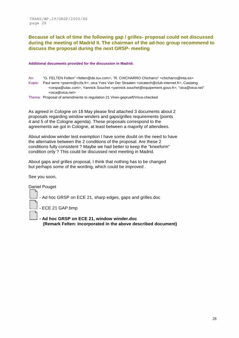
Because of lack of time the following gap / grilles- proposal could not discussedduring the meeting of Madrid II. The chairman of the ad-hoc group recommend todiscuss the proposal during the next GRSP- meeting
Additional documents provided for the discussion in Madrid:
An: "G. FELTEN Felten" <[email protected]>, "R. CHICHARRO Chicharro" <[email protected]>Kopie: Paul serre <[email protected]>, oica Yves Van Der Straaten <[email protected]>, Castaing
<[email protected]>, Yannick Souchet <[email protected]>, "[email protected]"<[email protected]>
Thema: Proposal of amendments to regulation 21 Viren-geprueft/Virus-checked
As agreed in Cologne on 18 May please find attached 3 documents about 2proposals regarding window winders and gaps/grilles requirements (points4 and 5 of the Cologne agenda). These proposals correspond to theagreements we got in Cologne, at least between a majority of attendees.
About window winder test exemption I have some doubt on the need to havethe alternative between the 2 conditions of the proposal. Are these 2conditions fully consistent ? Maybe we had better to keep the "kneeform"condition only ? This could be discussed next meeting in Madrid.
About gaps and grilles proposal, I think that nothing has to be changedbut perhaps some of the wording, which could be improved .
See you soon,
Daniel Pouget
- Ad hoc GRSP on ECE 21, sharp edges, gaps and grilles.doc
- ECE 21 GAP.bmp
- Ad hoc GRSP on ECE 21, window winder.doc(Remark Felten: Incorporated in the above described document)

29
Ad hoc GRSP on ECE 2113-14 September 2000
ECE 21, PROPOSAL OF AMENDMENT TO GAPS AND GRILLES REQUIREMENTS
(prepared by OICA, according to ad hoc GRSP meeting in Cologne, May 2000)
PROPOSAL
1°) Delete, within the explanatory notes, the whole § 5.1.1 on sharp edges and grilles (pages 18)
2°) Add a new § 2.10 (page 5)
2.10 A sharp edge is an edge of a rigid material having a radius of curvature of less than 2,5 mm, except in the case of projections of less than 3,2 mm, measured from the panel.
3°) Insert a new § 5.8 (page 13)
5.8 Common specifications
The following specifications apply to all interior parts of the passenger compartment which aredefined from paragraph 5.1 to paragraph 5.7 :
5.8.1 If the edge of a rigid material projects by less than 3,2 mm, this edge has not to be rounded to the minimum radius of curvature, provided the height of the projection is not more than half its width and this edge is blunted.
5.8.2 Grilles are considered to comply with the regulation if they meet the minimum requirements of the
following table :
(insert the existing table, page 18, of the current explanatory notes)
4°) Renumber existing § 5.8 and 5.8.1 as § 5.9 and 5.9.1
5°) Insert, within the explanatory notes, a new paragraph 2.10, after paragraph 2.7 (page 17)
Paragraph 2.10
In case of a gap between the edge of a rigid material and the panel, this edge shall be rounded to aminimum radius of curvature depending on the height of the projection, according to paragraphs 2.10 and5.8.1. This projection height has to be determined according to the procedure described in paragraph 1 ofannex 6 (See figure below).
(Insert new figure)
JUSTIFICATION
The requirements on sharp edges and grilles are indicated within the explanatory notes about § 5.1.1, concerningcomponents located within the reference zone. It is obvious that these requirements are as much worthwhile for otherzones, whatever the location of edges and grilles within the interior parts of the passenger compartment, which aredefined from § 5.1 to § 5.7.
____________

TRANS/WP.29/GRSP/2000/XXpage 30
30
Proposal made by OICA:
Insert a new paragraph 1.4.4 in annex 4 , PROCEDURE FOR TESTING ENERGY-DISSIPATING MATERIALS:
1.4.4.If an airbag is installed and covers at least part of the reference zone, the testmay be carried out with the airbag inflated at the request of the applicant
Justification:Alternative agreed in Cologne by a majority, but absent from the compilation byG. Felten
The above mentioned text has been discussed in Madrid II again with thefollowing result:
Agreed by: F, I, E, NL, OICADisagreed by S, D, UK serious reservation