draft regulatory guide ee 042-2, 'environmental
TRANSCRIPT

0 -U.S. NUCLEAR REGULATORY COMMISSION447°• OFFICE OF NUCLEAR REGULATORY RESEARCH February 1982
•• • Division 1
. DRAFT REGULATORY GUIDE AND VALUE/IMPACT STATEMENT Task EE 042-2
__ __ Contact: S. K. Aggarwal (301) 443-5946
PROPOSED REVISION 1 TO REGULATORY GUIDE 1.89
ENVIRONMENTAL QUALIFICATION OF ELECTRIC 'IENTFOR NUCLEAR POWER PLANTS
A. INTRODUCTION
The Commission's regulations in 10 CFR Par 5 >Wmestic Licensing of
Production and Utilization Facilities," require th tructures, systems, and
components important to safety in a nuclear" V pyi• Tant be designed to accom-
modate the effects of environmental condc i.e., remain functional under
postulated accident conditions) and th - n control measures such as test-
ing be used to check the adequacy of qjn., These general requirements are
contained in General Design Criter /•.•'•',--"2"\ 4, and 23 of Appendix A, "General
Design Criteria for Nuclear Power 1l " to Part 50; in Criterion III,
"Design Control," and Criterio×XI,` est Control," of Appendix B, "Quality
Assurance Criteria for Nuclear i lants and Fuel Reprocessing Plants," to
Part 50; and in § 50. 55a.
Specific requirements 'c&ectric equipment important to safety are
contained in a proposed amendment to 10 CFR Part 50. Section 50.49, "Environ-
mental Qualification of Electric Equipment for Nuclear Power Plants," would
require that each p> electric equipment be qualified for its application
and specified pertfrp4ance and would provide requirements for establishing
qualification, e sh i and environmental qualification parameters.
This r,-t(rjo guide describes a method acceptable to the NRC staff for
complying~vi the Commission's regulations with regard to qualification
of electric ipment for service in nuclear power plants to ensure that the
equipment can perform its safety function.
This regulatory guide and the associated value/impact statement are being issued in draft form to involvethe public in the early stages of the development of a regulatory position in this area. They have notreceived complete staff review and do not represent an official NRC staff position.
Public comments are being solicited on both drafts, the guide (including any implementation schedule) andthe value/impact statement. Comments on the value/impact statement should be accompanied by supportingdata. Comments on both drafts should be sent to the Secretary of the Commission, U.S. Nuclear RegulatoryCommission, Washington, D.C. 20555, Attention: Docketing and Service Branch, by APR 2 3 1982Requests for single copies of draft guides (which may be reproduced) or for placement on an automaticdistribution list for single copies of future draft guides in specific divisions should be made inwriting to the U.S. Nuclear Regulatory Commission, Washington, D.C. 20555, Attention: Director,Division of Technical Information and Document Control.

B. DISCUSSION
IEEE Std 323-1974, "IEEE Standard for Qualifying Class IE Equipment for
Nuclear Power Generating Stations,"' dated February 28, 1974, was prepared by
Subcommittee 2, Equipment Qualification, of the Nuclear Power Engineering
Committee of the Institute of Electrical and Electronics Engineers (IEEE), and
subsequently was approved by the IEEE Standards Board on December 13, 1973.
The standard describes basic procedures for qualifying Class 1E equipment and
interfaces that are to be used in nuclear power plants, including components
or equipment of any interface whose failure could adversely affect any Class
1E equipment.
The requirements delineated include principles, procedures, and methods
of qualification that, when satisfied, will confirm the adequacy of the equip-
ment design for the performance of safety functions under normal, abnormal,
design-basis-event, post-design-basis-event, and containment-test conditions.
It is essential that equipment be qualified to meet its performance
requirements under the environmental and operating conditions in which it will
be required to function and for the length of time its function is required.
The following are examples of considerations to be taken into account when, deter-
mining the environment for which the equipment is to be qualified: (1) equip-
ment outside containment would generally see a less severe environment than
equipment inside containment; (2) equipment whose location is shielded from a
radiation source would generally receive a smaller radiation dose than equip-
ment at the same distance from the source but exposed to its direct radiation;
(3) equipment required to initiate protective action would generally be required
for a shorter period of time than instrumentation required to follow the course
of an accident. The specific environment for which individual equipment must
be qualified will depend on the installed location, the conditions under which
it is required to function, and the length of time (with margin) it is required
to operate.
Electric equipment to be qualified in a nuclear radiation environment should
be exposed to a fluence that simulates the conservatively calculated total dose
'Copies may be obtained from the Institute of Electrical and ElectronicsEngineers, Inc., United Engineering Center, 345 East 47th Street, New York,New York 10017.
2
and dose rate that the equipment should withstand prior to completion of its
intended function. Dose rate, spectrum, and particle type should be simulated
as closely as practicable unless it can be shown by analysis that damage is
not significantly dependent on dose rate, spectrum, or particle type.
Regulatory Position C.1 calls for the qualification of additional equipment
whose malfunction or failure resulting from an accident condition could negate
the safety function of essential systems and equipment.
Item (12) of Regulatory Position C.4.c addresses qualification of equipment
exposed to low-level radiation doses. Numerous studies that have compiled
radiation effects data on all classes of organic compounds show that compounds
with the least radiation resistance have damage thresholds greater than 104
rads and would remain functional with exposures somewhat above the threshold
value. Thus, for organic materials, radiation qualification may be readily
justified by existing test data or operating experience for radiation exposures.
below 104 rads. However, for electronic components, studies have shown failures
in metal oxide semiconductor devices at somewhat lower doses. Therefore,
radiation qualification for electronic components may have a lower exposure
threshold.
Equipment qualification is predicated on the assumption that qualification
testing adequately simulated the environment and service conditions throughout
the installed life of the equipment. Where routine maintenance is essential
to maintaining equipment in the conditions simulated by the qualification test
(e.g., cleanness), it is important to establish an adequate program of preventive
maintenance and quality assurance that includes minimizing dust accumulation
that could degrade the ability of the equipment to function properly.
C. REGULATORY POSITION
The procedures described by IEEE Std 323-1974, "IEEE Standard for Quali-
fying Class IE Equipment for Nuclear Power Generating Stations,"'1 dated Feb-
ruary 28, 1974, are acceptable to the NRC staff for qualifying electric equip-
ment for service in nuclear power plants to ensure that the equipment can
perform its safety functions subject to the following:
1. Proposed § 50.49, "Environmental Qualification of Electric Equipment
for Nuclear Power Plants," of 10 CFR Part 50 would require that essential
3

electric systems and equipment be qualified to perform their intended functions.
Typical essential equipment and functions that mitigate accidents are listed
in Appendix A to this guide. Additional equipment should also be qualified
for accident conditions if its malfunction or failure due to such conditions
will negate the safety function of essential systems and equipment. For
example, additional equipment that should be considered for qualification are
the associated circuits defined in Regulatory Guide 1.75, "Physical Independ-
ence of Electric Systems."
2. Reference is made in Sections 2, 6.3.2, and 6.3.5 of IEEE Std 323-1974
to IEEE Std 344-1971, "Guide for Seismic Qualification of Class 1 Electric
Equipment for Nuclear Power Generating Stations." The specific applicability
or acceptability of IEEE Std 344 is covered in Regulatory Guide 1.100, "Seismic
Qualification of Electric Equipment for Nuclear Power Plants." However, the
testing should be performed on a single prototype in the sequence indicated in
Section 6 of IEEE Std 323-1974.
3. Section 5, "Principles of Qualification," of IEEE Std 323-1974
presents various methods for qualifying equipment, including analysis. The
NRC generally will not accept analysis in lieu of testing. Experience has
shown that qualification of equipment without test data may not be adequate to
demonstrate functional operability during design basis event conditions.
Analysis may be acceptable if testing the equipment is impractical because of
size limitations or the state of the art. Analysis in combination with partial
type-test data that adequately supports the analytical assumptions and conclu-
sionsis acceptable if the purchase order for this equipment was executed prior
to May 23, 1980.
4. Section 6.2 of IEEE Std 323-1974 requires equipment specifications
to define performance and environmental requirements. In defining the
requirements called for in item (7) of Section 6.2, the following should be
used:
a. Temperature and Pressure Conditions Inside Containment for
Loss-of-Coolant Accident (LOCA) and Main Steam Line Break (MSLB)
(1) The following methods for calculating and establishing the
containment pressure and temperature envelopes to which equipment should be
qualified are acceptable to the NRC staff:
(a) Methods for calculating mass and energy release rates
for LOCAs and MSLBs are summarized in Appendix B to this guide. The calculations
4
should account for the time dependence and spatial distribution of these
variables. For example, superheated steam followed by saturated steam may be a
limiting condition and should be considered.
(b) For pressurized water reactors (PWRs) with a dry
containment, calculate LOCA or MSLB containment environment using CONTEMPT-LT
or equivalent industry codes. Additional guidance is provided in Section 6.2.1.1.
of NUREG-0800, "Standard Review Plan" 2 (SRP).
(c) For PWRs with an ice condenser containment, calculate
LOCA or MSLB containment environment using LOTIC or-equivalent industry codes.
.Additional guidance is provided in SRP Section 6.2.1.1.B.
(d) For boiling water reactors (BWRs) with a Mark I, II,
or III containment, calculate LOCA or MSLB environment using methods of GESSAR
Appendix 3B or equivalent industry codes. Additional guidance is provided in
SRP Section 6.2.1.1.C.
(2) Since the test profiles included in Appendix A to IEEE Std
323-1974 are only representative, they should not be considered an acceptable
alternative to using plant-specific containment temperature and pressure
design profiles unless plant-specific analysis is provided to verify the
applicability of those profiles.
b. Effects of Chemicals
Guidelines for the chemical spray are provided in SRP Sec-
tion 6.5.2, paragraph II, item (e). Effects of the spray should also be con-
sidered for plants that use demineralized water as spray solution.
c. Radiation Conditions Inside and Outside Containment
The radiation environment for qualification of equipment should
be based on the radiation environment normally expected over the installed life
of the equipment plus that associated with the most severe accident during or
following which the equipment must remain functional. It should be assumed
that the accident-related environmental conditions occur at the most critical
point of degradation during the installed life of the equipment, which may be
at the end of its installed life. Methods acceptable to the NRC staff for
2 Copies may be obtained at current prices from the National TechnicalInformation Service, Springfield, Virginia 22161.
5

establishing radiation limits for the qualification of equipment for BWRs and
PWRs are provided in the sample calculations in Appendix C and the following:
(1) The source term to be used in determining the radiation
environment for equipment qualification associated with a LOCA should consider
the most limiting environment associated with the following:
(a) For a LOCA in which the primary system cannot be
restored, 100% of the core activity inventory of noble gases and 50% of the
core activity inventory of halogens should be assumed to be instantaneously
released from the fuel to the containment. Fifty percent of the core activity
inventory of cesium and 1% of the remaining fission product solids should be
assumed to be instantaneously released from the fuel to the primary coolant
and carried by the coolant to the containment sump.
(b) For a LOCA in which the primary system integrity can
be restored, 100% of the core activity inventory of noble gases, 50% of the
core activity inventory of halogens, 50% of the core activity inventory of
cesium, and 1% of the remaining fission product solids should be assumed to be
instantaneously released (after an initial time delay) and circulated in the
primary coolant system. This accident is not expected to produce instantaneous
fuel damage. A 30-minute delay may be assumed for fission product release from
the fuel. Greater delay times should be justified on the basis of system design
that minimizes fission product release. No noble gases should be assumed
circulating in the primary system following system depressurization.
(2) For all other design basis accidents (e.g., non-LOCA high-
energy line breaks or rod ejection or rod drop accidents) the qualification
source term calculations should use the percentage of fuel damage assumed in
the plant-specific analysis (provided in the FSAR). When only fuel clad per-
foration is postulated, the nuclide inventory of the fuel elements breached
should be calculated at the end of core life, assuming continuous full-power
operation. The fuel rod gap inventory should be assumed to be 10% of the
total rod activity inventory of iodine and 10% of the total activity inven-
tory of'noble gases (except for Kr-85, for which a release of 30% should be
assumed). All the gaseous constituents in the gaps of the breached fuel rods
should be assumed instantaneously released to the primary coolant. When fuel
melting is postulated, the activity inventory of the melted fuel elements
should also be calculated at the end of core life assuming full-power operation.
6
For this case, 100% of the noble gases, 50% of the halogens, 50% of the cesium,
and 1% of the remaining fission product solids in these elements should be
assumed to be instantaneously released to the primary coolant.
(3) For a limited number of accident-monitoring instrumentation
channels with instrument ranges that extend well beyond the values the selected
variables can attain under limiting conditions as specified in Regulatory
Guide 1.97, "Instrumentation for Light-Water-Cooled Nuclear Power Plants to
Assess Plant and Environs Conditions During and Following an Accident," the
source term should assume an initial release to the containment that considers
the fission product release groups associated with grossly melted fuel. Accept-
able assumptions for the fractional release for each group are: noble gases,
100%; I, Br, 100%; Cs, Rb, 100%; Te, 100%; Sr, Ba, 11%; Ru, 8%; and La, 1.3%
(individual nuclides are listed in Table VI 3-1 of WASH-1400). The effect of
natural and mechanical containment fission product removal may be considered
on a best-estimate basis to determine the rate of redistribution of the various
groups from the containment atmosphere to other locations.
(4) The calculation of the radiation environment associated
with design basis accidents should take into account the time-dependent transport
of released fission products within various regions of containment and auxiliary
structures.
(5) The initial distribution of activity within the containment
should be based on mechanistic assumptions. For example, for compartmented
containments such as in some BWRs, it should be assumed that 100% of the source
is initially contained in the drywell. For ice condenser containments, it should
be assumed that 100% of the source is initially contained in the lower portion
of the containment. The assumption of uniform distribution of activity
throughout a compartmented containment at time zero may not be appropriate.
(6) Effects of the engineered safety feature systems that act
to remove airborne activity and redistribute activity within containment,
e*g., containment sprays and containment ventilation and filtration systems,
should be calculated using the same assumptions used in the calculation of
offsite dose. See SRP Section 15.6.5 and the related sections referenced in
the appendices to that section.
(7) Natural deposition (i.e., piateout) of airborne activity
should he determined using a mechanistic model and best estimates for the model
parameters (see Ref. 3, Appendix C). The assumption of 50% instantaneous
7
plateout of the iodine released from the core should not be made. Removal of
iodine from surfaces by steam condensate flow or washoff by the containment
spray may be assumed if such effects can be verified and quantified by analysis
or experiment.
(8) The qualification dose should be the sum of the calculated
doses of the potential radiation sources at the equipment location (i.e., beta
and gamma). Plant-specific analysis may be used to justify any reduction in
dose or dose rate due to the specific location or shielding. The qualification
dose may be established by one of the following:
(a) The total qualification dose should be equivalent to
the total calculated dose (beta plus gamma) at the equipment location. A
source of gamma radiation only may be used for qualification testing provided
analysis or tests indicate that the doses and dose rates produce damage similar
to the damage that would occur under accident conditions, i.e., a combination
of beta and gamma radiation, or
(b) The beta and gamma qualification doses may be
determined separately and the testing may be performed using both a beta and a
gamma test source.
(9) Shielded components need be qualified only to the gamma
radiation dose or dose rate required provided an analysis or test shows that
the sensitive portions of the component or equipment are not exposed to sig-
nificant beta radiation dose rates or that the effects of beta radiation heating
and secondary radiation have no deleterious effects on component performance.
(10) Coatings and coverings on electric equipment should be
assumed to be exposed to both beta and gamma dose and dose rates in assessing
their resistance to radiation. Plateout activity should be assumed to remain
on the equipment surface unless the effects of removal mechanisms such as spray
washoff or steam condensate flow can be verified and quantified by analysis or
experiment.
(11) Equipment located outside containment that is exposed to a
recirculating fluid should be qualified to withstand the radiation penetrating
the containment plus the radiation from the recirculating fluid.
(12) Equipment that may be exposed to low-level radiation doses
should not generally be considered exempt from radiation qualification testing.
Exemption may be based on qualification by analysis supported by test data or
operating experience that verifies that the dose and dose rates will not
degrade the operability of the equipment below acceptablevalues.
8

(13) A given component may be considered to be qualified provided
it can be shown that the component can be subjected, without failing, to inte-
grated beta and gamma doses, taking into account the beta and gamma dose rates,
equal to or higher than those levels resulting from an analysis that (a) is
similar in nature and scope to that included in Appendix C and (b) incorporates
appropriate factors pertinent to the plant design (e.g., reactor type and power
level, containment size).
d. Environmental Conditions for Equipment Outside Containment
(1) Equipment that is located outside containment and that could
be subjected to high-energy pipe breaks as defined in the Standard Review Plan
should be qualified to the conditions resulting from the accident for the dur-
ation required. The techniques to calculate the environmental conditions should
employ a plant-specific model based on good engineering judgment.
(2) Equipment located in general plant areas outside containment
where equipment is not subjected to a design basis accident environment should
be qualified to the normal and abnormal range of environmental conditions
postulated to occur at the equipment location.
(3) Equipment not served by environmental support systems within
the scope of this guide or served by other systems within the scope of this
guide that may be secured during plant operation or shutdown should be qualified
to the limiting environmental conditions that are postulated for that location,
assuming a loss of the environmental support system.
5. Section 6.3, "Type Test Procedures," of IEEE Std 323-1974 should be
supplemented with the following:
a,. Equipment items identified in items (2) and (3) of Regulatory
Position C.4.d are not required to be qualified by test if they are in a mild
environment, i.e., an environment that would at no time be more severe than
the environment that would occur during normal power plant operation or during
anticipated operational occurrences. Design or purchase specifications that
contain a description of the functional requirements and the specific environ-mental conditions during normal and abnormal conditions and that are supported
by a certificate of compliance based on test data and analysis will generally
be acceptable. A well-supported surveillance program in conjunction with a
good preventive maintenance program should be provided to ensure that such
equipment will function for its design life.
9

b. Equipment located in watertight enclosures should be qualified
by testing that demonstrates the adequacy of such protection. Equipment that
could be submerged should be identified and demonstrated to be qualified by
testing that demonstrates seal integrity and functional operability for the
duration required. Shortened test periods and analytical extrapolation should
be justified.
c. Equipment located in an area where rapid pressure changes are
expected should be qualified by testing that demonstrates that, under the most
adverse time-dependent relative humidity conditions (superheated steam followed
by saturated steam may be a limiting condition) and the most adverse postulated
pressure transient for the equipment location, the equipment seals and vapor
barriers will prevent moisture from penetrating into the equipment to the degree
necessary to maintain equipment integrity for the length of time the equipment
function is required.
d. The temperature to which equipment is being qualified by exposure
to a simulated environment should be determined by temperature readings suf-
ficiently close to the equipment to characterize its environment.
e. Performance characteristics of equipment should be verified before,
after, and periodically during testing throughout its range of required oper-
ability. Variables indicative of momentary failure, e.g., momentary opening
of a relay contact, should be monitored continuously to ensure that spurious
failures (if any) have been accounted for during testing. For long-term test-
ing, however, continuous monitoring during periodic intervals may be used if
justified.
f. Chemical spray or demineralized water spray should be incorporated
during simulated event testing at or near the maximum pressure and temperature
conditions that would occur when the spray systems actuate.
g. Expected extremes in power supply voltage and frequency should
be applied appropriately during simulated event testing.
h. Cobalt-60 or cesium-137 would be acceptable gamma radiation
sources for environmental qualification.
6. In the absence of plant-specific margins, the suggested values in
Section 6.3.1.5, "Margin," of IEEE Std 323-1974 may be used as a guide subject
to the following:
a. Quantified margins should be applied to the design parameters
discussed in Regulatory Position C.4 to ensure that the postulated accident
10
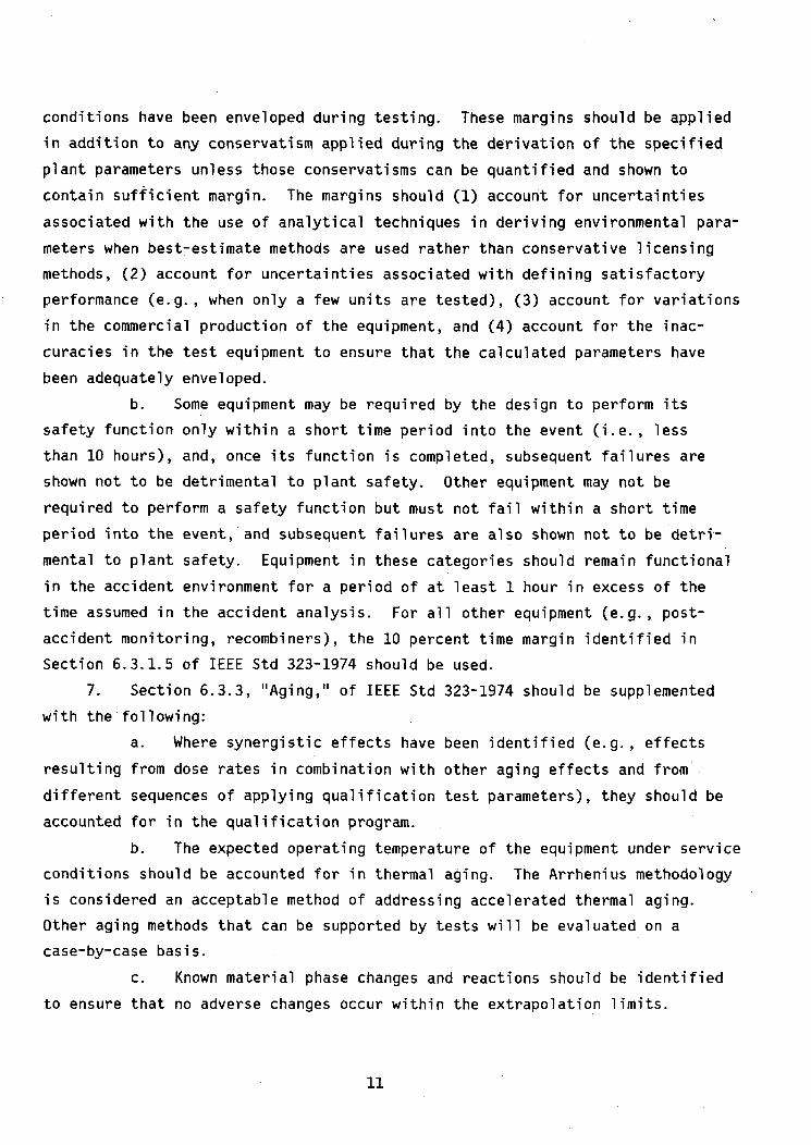
conditions have been enveloped during testing. These margins should be applied
in addition to any conservatism applied during the derivation of the specified
plant parameters unless those conservatisms can be quantified and shown to
contain sufficient margin. The margins should (1) account for uncertainties
associated with the use of analytical techniques in deriving environmental para-
meters when best-estimate methods are used rather than conservative licensing
methods, (2) account for uncertainties associated with defining satisfactory
performance (e.g., when only a few units are tested), (3) account for variations
in the commercial production of the equipment, and (4) account for the inac-
curacies in the test equipment to ensure that the calculated parameters have
been adequately enveloped.
b. Some equipment may be required by the design to perform its
safety function only within a short time period into the event (i.e., less
than 10 hours), and, once its function is completed, subsequent failures are
shown not to be detrimental to plant safety. Other equipment may not be
required to perform a safety function but must not fail within a short time
period into the event, and subsequent failures are also shown not to be detri-
mental to plant safety. Equipment in these categories should remain functional
in the accident environment for a period of at least 1 hour in excess of the
time assumed in the accident analysis. For all other equipment (e.g., post-
accident monitoring, recombiners), the 10 percent time margin identified in
Section 6.3.1.5 of IEEE Std 323-1974 should be used.
7. Section 6.3.3, "Aging," of IEEE Std 323-1974 should be supplemented
with the following:
a. Where synergistic effects have been identified (e.g., effects
resulting from dose rates in combination with other aging effects and from
different sequences of applying qualification test parameters), they should be
accounted for in the qualification program.
b. The expected operating temperature of the equipment under service
conditions should be accounted for in thermal aging. The Arrhenius methodology
is considered an acceptable method of addressing accelerated thermal aging.
Other aging methods that can be supported by tests will be evaluated on a
case-by-case basis.
c. Known material phase changes and reactions should be identified
to ensure that no adverse changes occur within the extrapolation limits.
11

d. The aging acceleration rate and activation energies used during
qualification testing and the basis upon which the rate and activation energy
were established should be defined, justified, and documented.
e. Periodic surveillance testing under normal service conditions
is not considered an acceptable method for ongoing qualification unless the
testing includes provisions for subjecting the equipment to the limiting service
and environmental conditions (specified in accordance with proposed para-
graph 50.49(c) of 10 CFR Part 50).
f. Humidity effects should be included in accelerated aging unless
it can be shown that the effects of relative humidity are negligible.
g. The qualified life of the equipment (or component, as applicable)
and the basis for its selection should be defined and documented.
h. Qualified life should be established on the basis of the severity
of the testing performed, the conservatisms employed in the extrapolation of
data, the operating history, and the other methods that may reasonably be used.
All assumptions should be documented.
i. An ongoing program to review surveillance and maintenance records
to identify age-related degradations should be established.
j. A component maintenance and replacement schedule that includes
consideration of aging characteristics of the installed components should be
established.
8. Sections 6.4 and 6.5 of IEEE Std 323-1974 discuss qualification by
operating experience and by analysis, respectively. The adequacy of these
methods should be evaluated on the basis of the quality and detail of the infor-
mation available in support of the assumptions made. Operating experience and
analysis based on test data may be used where testing is precluded by the
physical size of the equipment or the state of the art of testing. When the
analysis method is employed because of the physical size of the equipment,
tests on vital components of the equipment should be provided.
9. Components that are part of equipment qualified as an assembly
(e.g., a motor starter that is part of a motor control center qualified as a
whole) may be replaced with components of the same design. If components of
the same design are not used for replacement, the replacement component should
be designed to meet the performance requirements and should be qualified to
meet the service conditions specified for the original components.
12
10. In addition to the requirements of Section 8, "Documentation," of
IEEE Std 323-1974, documentation should address the information identified in
Appendix D to this guide. A certificate of conformance by itself is not accept-
able unless it is accompanied by information on the qualification program,
including test data or comparable test data from equivalent equipment. A record
of the qualification should be maintained in a central file to permit verifica-
tion that each item of electric equipment is qualified for its application and
meets its specified performance requirements when subjected to the conditions
present when it must perform its safety function up to the end of its qualified
life.
D. IMPLEMENTATION
The purpose of this section is to provide information to applicants and
licensees regarding the NRC staff's plans for using this regulatory guide.
Except in those cases in which the applicant proposes an acceptable
alternative method for complying with specified portions of the Commission's
regultions, the methods described herein will be used in the evaluation of the
qualification of electric equipment for all operating plants and plants that
have not received an operating license subject to the following:
1. Plants that are not committed to either IEEE Std 323-1971 or the
November 1974 issue of Regulatory Guide 1.89/IEEE Std 323-1974 and whose equip-
ment has been tested only for a high-temperature, high-pressure, and steam
environment may not need to test such equipment again to include other service
conditions such as radiation and chemical sprays. The qualification of equipment
for these service conditions may be established by analysis.
2. The provision that testing should be performed on a single prototype
in the sequence indicated in Section 6 of IEEE Std 323-1974 will be waived for
operating power plants.
3. With regard to aging considerations in equipment qualification, plants
that are not committed to the November 1974 issue of Regulatory Guide 1.89/
IEEE Std 323-1974 need not demonstrate a specific qualified life except in the
case of equipment using materials that have been identified as being susceptible
to significant degradation due to aging. Component maintenance or replacement
schedules should include considerations of the specific aging characteristics
of the component materials. Ongoing programs should exist at the plant to review
surveillance and maintenance records to ensure that equipment exhibiting
age-related degradation will be identified and replaced as necessary. However,
the valve operators and the motors should be preconditioned by aging prior to
testing for those plants that are committed to Regulatory Guide 1.73, "Qualifi-
cation Tests of Electric Valve Operators Installed Inside the Containment of
Nuclear Power Plants," which endorses IEEE Std 382-1972, and Regulatory
Guide 1.40, "Qualification Tests of Continuous-Duty Motors Installed Inside
the Containment of Water-Cooled Nuclear Power Plants," which endorses IEEE Std
334-1971.
4. Replacement components or spare parts used to replace currently
installed equipment or components should be qualified according to this guide
unless there are sound reasons to the contrary. Unavailability of prototype
equipment or the fact that the component to be used as a replacement is in
stock or was purchased prior to May 23, 1980, are among the factors to be
considered in weighing whether there are sound reasons to the contrary.
14
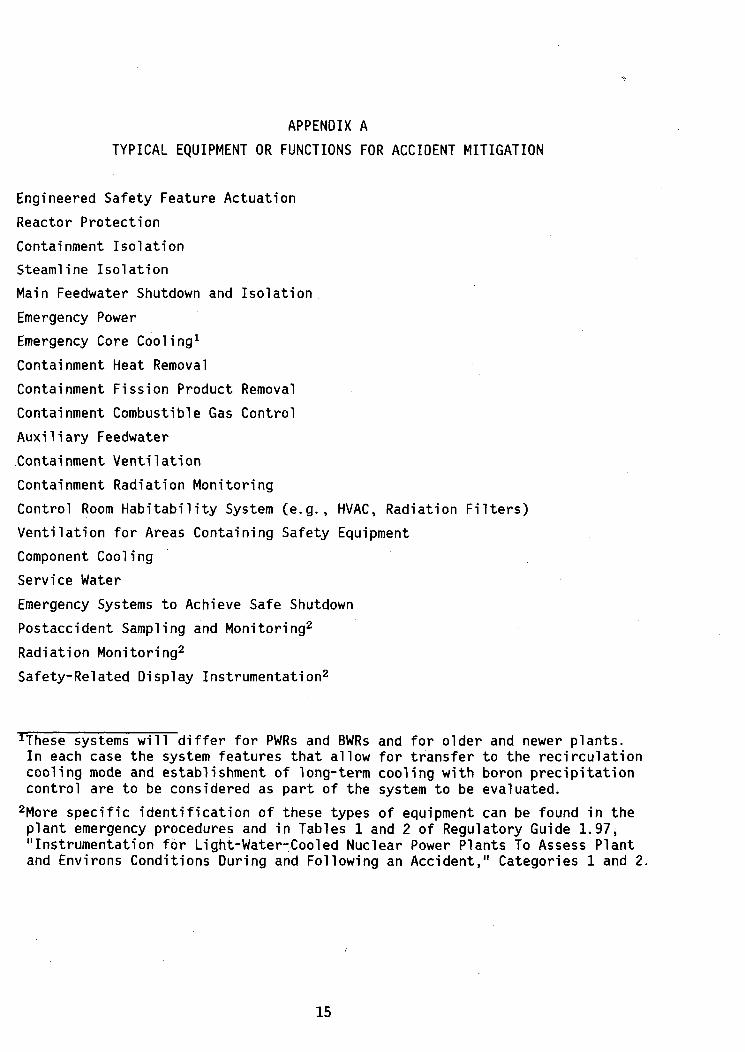
APPENDIX A
TYPICAL EQUIPMENT OR FUNCTIONS FOR ACCIDENT MITIGATION
Engineered Safety Feature Actuation
Reactor Protection
Containment Isolation
Steamline Isolation
Main Feedwater Shutdown and Isolation
Emergency Power
Emergency Core Cooling'
Containment Heat Removal
Containment Fission Product Removal
Containment Combustible Gas Control
Auxiliary Feedwater
Containment Ventilation
Containment Radiation Monitoring
Control Room Habitability System (e.g., HVAC, Radiation Filters)
Ventilation for Areas Containing Safety Equipment
Component Cooling
Service Water
Emergency Systems to Achieve Safe Shutdown
Postaccident Sampling and Monitoring2
Radiation Monitoring2
Safety-Related Display Instrumentation 2
'These systems will differ for PWRs and BWRs and for older and newer plants.In each case the system features that allow for transfer to the recirculationcooling mode and establishment of long-term cooling with boron precipitationcontrol are to be considered as part of the system to be evaluated.
2 More specific identification of these types of equipment can be found in theplant emergency procedures and in Tables 1 and 2 of Regulatory Guide 1.97,"Instrumentation for Light-Water-Cooled Nuclear Power Plants To Assess Plantand Environs Conditions During and Following an Accident," Categories 1 and 2.
15
APPENDIX B
METHODS FOR CALCULATING MASS AND ENERGY RELEASE
Loss-of-Coolant Accident
Acceptable methods for calculating the mass and energy release to determine
the loss-of-coolant accident environment for PWR and BWR plants are
described in the following:
1. Topical Report WCAP-8312A for Westinghouse plants.
2. Section 6.2.1 of CESSAR System 80 PSAR for Combustion Engineering
plants.
3. Appendix 6A of B-SAR-205 for Babcock & Wilcox plants.
4. NEDO-10320 and Supplements 1 & 2 for General Electric plants.
NEDO-20533 dated June 1974 and Supplement 1 dated August 1975
(GE Mark III).
Main Steam Line Break
Acceptable methods for calculating the mass and energy release to determine
the main steam line break environment are described in the following:
1. Topical Report WCAP-8822 for Westinghouse plants. (Although this
Topical Report is currently under review, the use of this method
is acceptable in the interim if no entrainment is assumed. Reanalysis
may be required following the NRC staff review of'the entrainment
model as presently described.)
2. Appendix 6B of CESSAR System 80 PSAR for Combustion Engineering
plants.
3. Section 15.1.14 of B-SAR-205 for Babcock & Wilcox plants.
4. Same as item 4 above for General Electric plants.
16
APPENDIX C
SAMPLE CALCULATION AND METHODOLOGYFOR RADIATION QUALIFICATION DOSE
This appendix illustrates the staff model for calculating dose rates and
integrated doses for equipment qualification purposes. The doses shown in
Figure B-1 include contributions from airborne and plateout radiation sources
in the containment and cover a period of one year following the postulated
fission product release. The dose values shown here are provided for illus-
tration only and may not be appropriate for plant-specific application for
equipment qualification levels. The dose levels intended for qualification
purposes should be determined using the maximum time the equipment is intended
to function, which, for the design basis loss-of-coolant accident (LOCA), may
well exceed one year.
The beta and gamma integrated doses presented in Tables B-1 and B-2 and
Figure B-1 have been determined using models and assumptions contained in this
appendix. This analysis is conservative and incorporates the important time-
dependent phenomena related to the action of engineered safety features (ESFs)
and such natural phenomena as iodine plateout, as in previous staff analyses.
Doses were calculated for a point inside the containment (at the midpoint
of the containment) taking sprays and plateout mechanisms into account. The
doses presented in Figure B-1 are values for a PWR plant having a containment
free volume of 2.5 million cubic feet and a power rating of 4100 MWt.
1. Basic Assumptions Used in the Analysis
Gamma and beta doses and dose rates should be determined for three types
of radioactive source distributions: (1) activity suspended in the containment
atmosphere, (2) activity plated out on containment surfaces, and (3) activity
mixed in the containment sump water. A given piece of equipment may receive a
dose contribution from any or all of these sources. The amount of dose contrib-
uted by each of these sources is determined by the location of the equipment,
the time-dependent and location-dependent distribution of the source, and the
effects of shielding.
17

Following the accident at Three Mile Island Unit 2 (TMI-2), the staff
concluded that a thorough examination of the source term assumptions for equip-
ment qualification was warranted. It is recognized, however, that the TMI-2
accident represents only one of a number of possible accident sequences lead-
ing to a release of fission products and that the mix of fission products
released under various core conditions could vary substantially. Current rule-
making proceedings are reevaluating plant siting policy, degraded cores, minimum
requirements for engineered safety features, and emergency preparedness. These
rulemaking activities also included an examination of fission product releases
under degraded core conditions. While the final resolution of the source term
assumptions is conditioned on the completion of these rulemaking efforts, the
staff believes it is prudent to incorporate the knowledge gained of fission
product behavior from the TMI-2 accident in defining source term assumptions
for equipment qualification.
Based on release estimates in the Rogovin Report (Ref. 1), the staff
assumptions for noble gas and iodine releases still appear to be conservative.
However, the report estimates that the TMI-2 release contained between 40 and
60 percent of the Cs-134 and Cs-137 core activity in the primary system water,
in the containment sump water, and in auxiliary building tanks. Comparison of
the integrated dose from the TMI-2 cesium release to the previous staff assump-
tion of "1% solids" shows that assuming "1% solids" may not result in a con-
servative estimate for the radiation exposure for equipment required to func-
tion for time periods exceeding thirty days. The staff feels that as a first
step toward modification of the TID-14844 source term in the direction indi-
cated by the TMI-2 experience, it may be prudent to include a cesium release
in addition to the previously assumed "1% solids." As a result, the revised
regulatory positions propose a release of 50% of the core cesium activity
inventory (see Regulatory Position C.4.c items (1) and (2)). The assumed
cesium release implies no substantial departure from, and is consistent with,
the degraded core conditions previously implied by the assumed release of 50%
of the core iodine activity. This change in assumption would have particular
significance for the qualification of equipment in the vicinity of recirculat-
ing fluids and for equipment required to function for time periods exceeding
30 days.
18

The assumption of concurrent release of cesium and iodine also is con-
sistent with the findings of recent source term studies reported in NUREG-0772
(Ref. 2). This report also concluded that the predominant form of the iodine
released during accidents is cesium iodide (CsI). Although the CsI form is
not specifically addressed in this report, it is evident that either CsI or
12 and Cs would, in the long term, be located primarily in the reactor water
and the containment sump water of a PWR or the suppression pool of a BWR.
The staff recognizes that the revised source terms contained in this report
are interim values and that the conclusions from the report cited above, as
well as further results from current research efforts in the source term area,
should ultimately form the basis for any revision of source term assumptions.
Any revision of the source term assumptions, such as the inclusion of additional
radionuclides, would be incorporated into this guide before it is issued as an
active guide.
2. Assumptions Used in Calculating Fission Product Concentrations
This section discusses the assumptions used to simulate the PWR and BWR
containments for determining the time-dependent and location-dependent distri-
bution of the noble gas and iodine activity airborne within the containment
atmosphere, the activity plated out on containment surfaces, and the activity
in the sump water.
The staff used a computer program, TACT, to model the time-dependent
behavior of iodine and noble gases within a nuclear power plant. The TACT
code or other equivalent industry codes would provide an acceptable method for
modeling the transfer of activity from one containment region to another and
in modeling the reduction of activity due to the action of ESFs. Another staff
code, SPIRT (Ref. 3), is used to calculate the removal rates of elemental iodine
by plateout and sprays. These codes were used to develop the source term
estimates. The assumptions in the following sections were used to calculate
the distribution of radioactivity within the containment following a design
basis LOCA.
2.1 PWR Dry Containments
The following methods and assumptions were used by the staff for calcu-
lating the radiation environment in PWR dry containments:
19
1. The source terms used in the analysis assumed that 50% of the core
iodines and 100% of the core noble gases were released instantaneously to the
containment atmosphere and 50% of the core cesium and 1% of the remaining"solid" activity inventory were released from the core and carried with the
primary coolant directly to the containment sump.
6 32. The containment free volume was taken as 2.52 x 10 ft 3 . Of this
volume, 74% or 1.86 x 106 ft 3 was assumed to be directly covered by the
containment sprays. (Plants with different containment free volumes should
use plant-specific values.)
3. It was assumed that 6.6 x 105 ft3 of the containment free volume is
unsprayed; this includes regions within the main containment space under the
containment dome and compartments below the operating floor level.
4. The ESF fans were assumed to have a design flow rate of 220,000 cfm
in the post-LOCA environment. Mixing between all major unsprayed regions and
compartments and the main sprayed region was assumed.
5. Air exchange between the sprayed and unsprayed region was assumed to
be one-half of the design flow rate of ESF fans. Good mixing of the containment
activity between the sprayed and unsprayed regions is ensured by natural
convection currents and ESF fans.
6. The containment spray system was assumed to have two equal capacity
trains, each designed to inject 3000 gpm of boric acid solution into the
containment.
7. Trace levels of hydrazine were assumed to be added to enhance the
removal of iodine.
8. The spray removal rate constant (X) was calculated using the staff's
SPIRT program, conservatively assuming the operation of only one spray train
and an instantaneous partition coefficient (H) for elemental iodine of 5000.
The calculated value of the spray removal constant for elemental iodine was
27.2 hr 1
20
9. Plateout of iodine on containment internal surfaces was modeled as a
first-order rate removal process and best estimates for model parameters were
assumed. Based on an assumed total surface area within containment of approxi-
mately 5.0 x 105 ft 2 , the calculated value for the overall plateout constant
for elemental iodine was 1.23 hr- 1. The assumption that 50% of the activity
is instantaneously plated out should not be used.
10. The spray removal and plateout processes were modeled as competing
iodine removal mechanisms.
11. A spray removal rate constant (A) for particulate iodine concentration
was calculated using the staff's SPIRT program (Ref. 3). The staff calculated
a value of X = 0.43 hr-1 and allowed the removal of particulate iodine to con-
tinue until the airborne concentration was reduced by a factor of 10 4. The
organic iodine concentration in the containment atmosphere is assumed not to
be affected by either the containment spray or plateout removal mechanisms.
12. The sprays were assumed to remove elemental iodine until the instan-
taneous concentration in the sprayed region was reduced by a factor of 200.
This is necessary to achieve an equilibrium airborne iodine concentration
consistent with previous LOCA analyses.
13. A relatively open (not compartmented) containment was assumed, and
the large release was uniformly distributed in the containment. This is an
adequate simplification for dose assessment in a PWR containment and is
realistic in terms of specifying the time-dependent radiation environment in
most areas of the containment.
14. The analysis assumed that more than one specie of radioactive iodine
is present in a design basis LOCA. The calculation of the post-LOCA environ-
ment assumed that, of the 50% of the core inventory of iodine released, 2.5%
is associated with airborne particulate materials and 2% formed organic com-
pounds. The remaining 95.5% remains as elemental iodine. For conservatism,
this composition was assumed present at time t = 0. (These assumptions con-
cerning the iodine form are consistent with those of Regulatory Guides 1.3,
21
"Assumptions Used for Evaluating the Potential Radiological Consequences of a
Loss of Coolant Accident for Boiling Water Reactors," and 1.4, "Assumptions.
Used for Evaluating the Potential Radiological Consequences of a Loss of
Coolant Accident for Pressurized Water Reactors," when a plateout factor of
2 is assumed for the elemental form.)
15. For all containments, no leakage from the containment building to
the environment was assumed.
16. Removal of airborne activity by engineered safety features may be
assumed when calculating the radiation environment following other non-LOCA
design basis accidents provided the safety features systems are automatically
activated as a result of the accident.
2.2 PWR Ice Condenser Containments
The assumptions and methods presented for calculating the radiation
environment in PWR dry containments are appropriate for use in calculating the
radiation environment for ice condenser containments following a design basis
LOCA with the following modifications:
1. The source should be assumed to be initially released to the lower
containment compartment. The distribution of the activity should be based on
the forced recirculation fan flow rates and the transfer rates through the ice
beds as functions of time.
2. Credit may be taken for iodine removal via the operation of the ice
beds and the spray system. A time-dependent removal efficiency consistent with
the steam/air mixture for elemental iodine may be assumed.
3. Removal of airborne iodine in the upper compartment of the contain-
ment by the action of both plateout and spray processes may be assumed provided
these removal processes are evaluated using conditions and assumptions consistent
with items 8 through 12 in Section 2.1 and plant-specific parameters.
22
2.3 BWR Containments
The assumptions and methods presented for calculating the radiation
environment in PWR dry containments are appropriate for use in calculating the
radiation environment for BWRs following a design basis LOCA with the following
modifications:
1. A decontamination factor (DF) of 10 may be assumed for both elemental
and particulate iodine as the iodine activity passes through the suppression
pool. No credit should be taken for the removal of organic iodine or noble
gases in the suppression pool.
2. For Mark III designs, all of the activity passing through the suppres-
sion pool should be assumed instantaneously and uniformly distributed within
the containment. For the Mark I and Mark II designs, all of the activity
should be assumed initially released to the drywell area and the transfer of
activity from these regions via containment leakage to the surrounding reactor
building volume should be used to predict the qualification levels within the
reactor building (secondary containment).
3. Removal of airborne iodine in the drywell or reactor building by the
action of both plateout and spray processes may be assumed provided the effec-
tiveness of these competing iodine removal processes are evaluated using condi-
tions and assumptions consistent with items 8 through 12 in Section 2.1 and
plant-specific parameters.
4. The removal of airborne activity from the reactor building by opera-
tion of the standby gas treatment system (SGTS) may be assumed.
3. Model for Calculating the Dose Rate of Airborne and Plateout Fission
Products
The beta and gamma dose rates and integrated doses from the airborne activ-
ity within the containment atmosphere were calculated for the midpoint in the
containment. The containment was modeled as a cylinder with the height and
diameter equal. Containment shielding and internal structures were neglected
23
because they would involve a degree of complexity beyond the scope of the pre-
sent work. The calculations of Reference 4 indicate that the specific internal
shielding and structure would be expected to reduce the gamma doses and dose
rates by factors of two or more depending on the specific location and geometry.
Because of the short range of the betas in air, the airborne beta doses
were calculated using an infinite medium approximation. This is shown in
Reference 5 to result in only a small error. Beta doses for equipment located
on the containment walls or on large internal structures may be calculated using
the semi-infinite beta dose model.
The gamma dose rate contribution from the plated-out iodine on containment
surfaces to the point on the centerline was also included. The model calcu-
lated the plateout activity in the containment assuming only one spray train
and one ventilation system were operating. It should be noted that washoff of
the plated-out iodine activity by the sprays was not addressed in this evaluation.
Finally, all gamma doses were multiplied by a correction factor of 1.3 as
suggested in Reference 5 to account for the omission of the contribution from
the decay chains of the isotopes.
4. Model for Calculating the Dose Rate of Sump Fission Products
The staff model assumed the washout of airborne iodine from the contain-
ment atmosphere to the containment sump. For a PWR containment with sprays and
good mixing between the sprayed and unsprayed regions, the elemental iodine
(assumed constituting 91% of the released iodine) is very rapidly washed out
of the atmosphere to the containment sump (typically 90% of the airborne iodine
in less than 15 minutes).
The dose calculations may assume a time-dependent iodine source. (The
difference between the integrated dose assuming 50% of the core iodine imme-
diately available in the sump versus a time-dependent sump iodine buildup is
not significant.)
The "solid" fission products should be assumed to be instantaneously
carried by the coolant to the sump and uniformly distributed in the sump water.
The gamma and beta dose rates and the integrated doses should be computed for
a center point located at the surface of the large pool of sump water and the
dose rates should be calculated including an estimate of the effects of buildup.
24
5. Conclusion
The values given in Tables C-I and C-2 and Figure C-I for the various
locations in the containment provide an estimate of expected radiation quali-
fication values for a 4100 MWt PWR design.
The NRC Office of Nuclear Regulatory Research is continuing its research
efforts in the area of source terms for equipment qualification following design
basis accidents. As more information in this area becomes available, the source
terms and staff models may change to reflect the new information.
25

Table C-1SUMMARY TABLE OF ESTIMATES FOR TOTAL AIRBORNE GAMMA DOSE
CONTRIBUTORS IN CONTAINMENT TO A POINT IN THE CONTAINMENT CENTER
Time Airborne Iodine Airborne Noble Plateout Iodine Total Dose(Hr) Dose (R) Gas Dose (R) Dose (R) (R)
0.00 -
0.03 4.82E+4 7.42E+4 1.69E+3 1.24E+50.06 8.57E+4 1.39E+5 3.98E+3 2.29E+50.09 1.09E+5 1.98E+5 7.22E+3 3.14E+50.12 1.25E+5 2.51E+5 1.10E+4 3.87E+50.15 1.38E+5 3.01E+5 1.52E+4 4.54E+50.18 1.47E+5 3.48E+5 1.96E+4 5.15E+50.21 1.55E+5 3.92E+5 2.41E+4 5.71E+50.25 1.64E+5 4.49E+5 3.03E+4 6.43E+50.38 1.87E+5 6.19E+5 5.05E+4 8.57E+50.50 2.03E+5 7.61E+5 6.90E+4 1.03E+60.75 2.36E+5 1.03E+6 1.06E+5 1.37E+61.00 2.66E+5 1.26E+6 1.40E+5 1.67E+62.00 3.62E+5 2.04E+6 2.61E+5 2.66E+65.00 5.50E+5 3.56E+6 5.40E+5 4.65E+68.00 6.63E+5 4.38E+6 7.47E+5 5.79E+624.0 1.01E+6 6.26E+6 1.45E+6 8.72E+660.0 1.31E+6 7.16E+6 2.10E+6 1.06E+796.0 1.45E+6 7.56E+6 2.39E+6 1.14E+7192. 1.68E+6 8.29E+6 2.86E+6 1.28E+7298. 1.85E+6 8.76E+6 3.19E+6 1.38E+7394. 1.95E+6 8.85E+6 3.41E+6 1.42E+7560 2.07E+6 9.06E+6 3.64E+6 1.48E+7720. 2.13E+6 9.15E+6 3.76E+6 1.50E+7888. 2.16E+6 9.19E+6 3.83E+6 1.52E+71060 2.18E+6 9.21E+6 3.87E+6 1.53E+61220 2.19+E6 9.21E+6 3.89E+6 1.53E+71390 2.20E+6 9.21E+6 3.90E+6 1.53E+71560 2.20E+6 9.22E+6 3.91E+6 1.53E+71730 2.20E+6 9.22E+6 3.91E+6 1.53E+71900 2.20E+6 9.22E+6 3.92E+6 1.53E+72060 2.20E+6 9.22E+6 3.92E+6 1.53E+72230 2.20E+6 9.22E+6 3.92E+6 1.53E+72950 2.20E+6 9.23E+6 3.92E+6 1.54E+73670 2.20E+6 9.24E+6 3.92E+6 1.54E+74390 2.20E+6 9.24E+6 3.92E+6 1.54E+75110 2.20E+6 9.25E+6 3.92E+6 1.54E+75830 2.20E+6 9.25E+6 3.92E+6 1.54E+76550 2.20E+6 9.26E+6 3.92E+6 1.54E+77270 2.20E+6 9.27E+6 3.92E+6 1.54E+78000 2.20E+6 9.27E+6 3.92E+6 1.54E+78710 2.20E+6 9.28E+6 3.92E+6 1.54E+7
TOTAL 1.54E+7
26
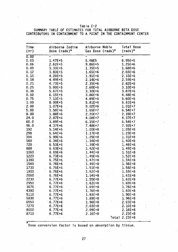
Table C-2SUMMARY TABLE OF ESTIMATES FOR TOTAL AIRBORNE BETA DOSE
CONTRIBUTORS IN CONTAINMENT TO A POINT IN THE CONTAINMENT CENTER
Time(hr)
0.000.030.060.090.120.150.180.210.250.380.500.751.002.005.008.0024.060.096.019229839456072088810601220139015601730190020602230295036704390511058306550727080008710
Airborne Iodine Airborne Noble Total DoseDose (rads)* Gas Dose (rads)* (rads)*
1.47E+5 5.48E5 6.95E+52.62E+5 9.86E+5 1.25E+63.33E+5 1.35E+5 1.68E+63*83E+5 1.65E+6 2.03E+64.20E+5 1.91E+6 2.33E+64.49E+5 2.14E+6 2.59E+64.73E+5 2.35E+6 2.82E+65.OOE+5 2.60E+6 3.10E+65.67E+5 3.30E+6 3.87E+66.15E+5 3.86E+6 4.48E+67.13E+5 4.89E+6 5.60E+68.OOE+5 5.81E+6 6.61E+61.07E+6 9.02E+6 1.01E+71.58E+6 1.65E+7 6.54E+71.88E+6 2.20E+7 2.39E+72.87E+6 4.08E+7 4.37E+73.89E+6 6.15E+7 6.54E+74.37E+6 7.48E+7 7.92E+75.14E+6 1.OOE+8 1.05E+85.64E+6 1.17E+8 1.23E+85.99E+6 1.25E+8 1.31E+86.34E+6 1.34E+8 1.40E+86.53E+6 1.39E+8 1.46E+86.63E+6 1.42E+8 1.49E+86.69E+6 1.44E+8 1.51E+86.73E+6 1.45E+8 1.52E+86.75E+6 1.47E+8 1.54E+86.76E+6 1.49E+8 1.56E+86.76E+6 1.51E+8 1.58E+86.76E+6 1.52E+8 1.59E+86.76E+6 1.54E+8 1.61E+86.77E+6 1.55E+8 1.62E+86.77E+6 1.62E+8 1.69E+86.77E+6 1.69E+8 1.76E+86.77E+6 1.76E+8 1.83E+86.77E+6 1.83E+8 1.90E+86.77E+6 1.89E+8 1.96E+86.77E+6 1.96E+8 2.03E+86.77E+6 2.03E+8 2.10E+86.77E+6 2.09E+8 2.16E+86.77E+6 2.16E+8 2.23E+8
Total 2.23E+8
Dose conversion factor is based on absorption by tissue.
27

10 09X-BETA DOSE(RADS)0-GAMMA DOSE(ROENTGEN)
I 10 08.HTE
R -A 10 07TE0
D0S 18 06.E
10 1'~ 1 of ae a 990i o 0aof al 4 1 j~ 02 9 goa a I swogga m i16 02 0 0 0204
TIME (HOURS)
Figure C-I Sample airborne doses for a dose point on the containment centerline

APPENDIX C
REFERENCES
1. Mitchell Rogovin, George T. Frampton, Jr., et al., "Three Mile Island--AReport to the Commissioners and to the Public," NUREG/CR-1250, Volume II,Part 2, April 5, 1979. Available for purchase from the National TechnicalInformation Service, Springfield, Virginia 22161.
2. "Technical Basis for Estimating Fission Product Behavior During LWR Acci-dents," NUREG-0772, June 1981. Available for purchase from the NationalTechnical Information Service, Springfield, Virginia 22161.
3. A. K. Postma, R. R. Sherry, and P. Tam, "Technological Bases for Modelsof Spray Washout and Airborne Contaminants in Containment Vessels,"NUREG/CR-0009, November 1978. Available for purchase from the NationalTechnical Information Service, Springfield, Virginia 22161.
4. E. A. Warman and E. T. Boulette, "Engineering Evaluation of RadiationEnvironment in LWR Containments," in Transactions of the American NuclearSociety, Vol. 23, pp. 604-605, 1976. Available in technical libraries.
5. M. J. Kolar and N. C. Olson, "Calculation of Accident Doses to EquipmentInside Containment of Power Reactors," in Transactions of the AmericanNuclear Society, Vol. 22, pp. 808-809, 1975. Available in technicallibraries.
BIBLIOGRAPHY
Kocher, D. C., ed., "Nuclear Decay Data for Radionuclides Occurring in RoutineReleases from Nuclear Fuel Cycle. Facilities," ORNL/NUREG/TM-102, August 1977.Available for purchase from the National Technical Information Service,Springfield, Virginia 22161.
Lorenz, R. A., J. L. Collins, and A. P. Malinauskas, "Fission Product SourceTerms for the LWR Loss-of-Coolant Accident: Summary Report," NUREG/CR-0091,May 1978. Available for purchase from the National Technical InformationService, Springfield, Virginia 22161.
Normand, E., and W. R. Determan, "A Simple Algorithm to Calculate the Immer-sion Dose,". in Transactions of the American Nuclear Society, Vol. 18, pp. 358-359,1974.. Available in technical libraries.
Postma, A. K., and R. Zavadoski, "Review of Organic Iodide Formation Under AccidentConditions in Water Cooled Reactors," WASH-1233, pp. 62-64, October 1972. Avail-able for purchase from the National Technical Information Service, Springfield,Virginia 22161.
29
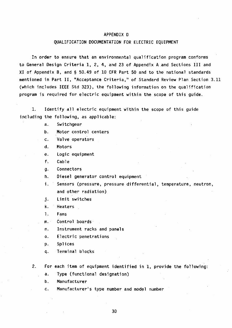
APPENDIX D
QUALIFICATION DOCUMENTATION FOR ELECTRIC EQUIPMENT
In order to ensure that an environmental qualification program conforms
to General Design Criteria 1, 2, 4, and 23 of Appendix A.and Sections III and
XI of Appendix B, and § 50.49 of 10 CFR Part 50 and to the national standards
mentioned in Part II, "Acceptance Criteria," of Standard Review Plan Section 3.11
(which includes IEEE Std 323), the following information on the qualification
program is required for electric equipment within the scope of this guide.
1. Identify all electric equipment within the scope of this guide
including the following, as applicable:
a. Switchgear
b. Motor control centers
c. Valve operators
d. Motors
e. Logic equipment
f. Cable
g. Connectors
h. Diesel generator control equipment
i. Sensors (pressure, pressure differential, temperature, neutron,
and other radiation)
j. Limit switches
k. Heaters
1. Fans
m. Control boards
n. Instrument racks and panels
o. Electric penetrations
p. Splices
q. Terminal blocks
2. For each item of equipment identified in 1, provide the following:
a. Type (functional designation)
b. Manufacturer
c. Manufacturer's type number and model number
30

3. Categorize the equipment identified in item I into one of the follow-
ing categories:
a. Equipment that will experience the environmental'conditions of
design basis accidents for which it must function to mitigate-such accidents
and that will be qualified to demonstrate operability in the accident environ-
ment for the time required for accident mitigation with safety margin to
failure.
b. Equipment that will experience environmental conditions of
design basis accidents through which it need not function for mitigation of
such accidents but through which it must not fail in a manner detrimental to
plant safety or accident mitigation and that will be qualified to demonstrate
the capability to withstand any accident environment for the time during which
it must not fail with safety margin to failure.
c. Equipment that will experience environmental conditions of
design basis accidents through which it need not'function for mitigation of
such accidents and whose failure (in any mode) is deemed not detrimental to
plant safety or accident mitigation and need not be qualified for any acci-
dent environment, but will be qualified for its normal service environment.
d. Equipment that will not experience environmental conditions of
design basis accidents and that will be qualified to demonstrate operability
under the expected extremes of.its normal service environment. This equipment
would normally be located outside the reactor containment.
4. For each item of equipment in the categories of equipment listed in
item 3, provide separately the equipment design specification requirements,
including:
a. The system safety function requirements.
b. An environmental envelope as a function of time that includes
all extreme parameters, both maximum and minimum values, expected to occur
31
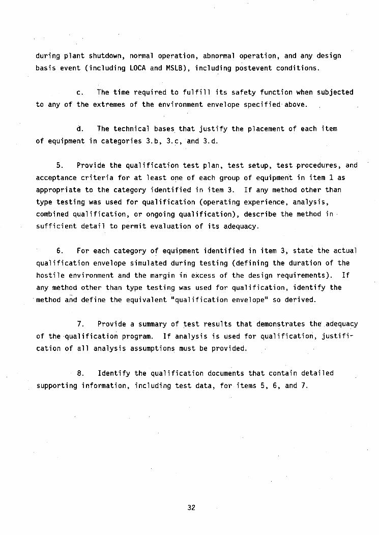
during plant shutdown, normal operation, abnormal operation, and any design
basis event (including LOCA and MSLB), including postevent conditions.
c. The time required to fulfill its safety function when subjected
to any of the extremes of the environment envelope specified-above.
d. The technical bases that justify the placement of each item
of equipment in categories 3.b, 3.c, and 3.d.
5. Provide the qualification test plan, test setup, test procedures, and
acceptance criteria for at least one of each group of equipment in item 1 as
appropriate to the category identified in item 3. If any method other than
type testing was used for qualification (operating experience, analysis,
combined qualification, or ongoing qualification), describe the method in
sufficient detail to permit evaluation of its adequacy.
6. For each category of equipment identified in item 3, state the actual
qualification envelope simulated during testing (defining the duration of the
hostile environment and the margin in excess of the design requirements). If
any method other than type testing was used for qualification, identify the
method and define the equivalent "qualification envelope" so derived.
7. Provide a summary of test results that demonstrates the adequacy
of the qualification program. If analysis is used for qualification, justifi-
cation of all analysis assumptions must be provided.
8. Identify the qualification documents that contain detailed
supporting information, including test data, for items 5, 6, and 7.
32

DRAFT VALUE/IMPACT STATEMENT
Background
Regulatory Guide 1.89, "Qualification of Class IE Equipment for Nuclear
Power Plants," issued in November 1974, is being revised to reflect the current
staff position on equipment qualification.
NUREG-0588, "Interim Staff Position on Environmental Qualification of
Safety-Related Electric Equipment," was issued for public comment in December
1979. Subsequent to its issuance for comment, the Commissioners (see Memorandum
and Order CLI-80-21 dated May 23, 1980) directed the staff to use NUREG-0588
along with a document entitled "DOR Guidelines for Evaluating Qualification of
Class 1E Electrical Equipment in Operating Reactors" as requirements licensees
and applicants must meet in order to satisfy the equipment qualification
requirements of 10 CFR Part 50. Additionally, the Commissioners directed the
staff to develop a rule for electric equipment qualification. The rule will
be based principally on NUREG-0588 and the DOR guidelines. The proposed revi-
sion to Regulatory Guide 1.89 will provide guidelines for meeting the Commis-
sion's equipment qualification rule and is essentially equivalent to the staff
position and guidance contained in the proposed revised version of NUREG-0588,
which is based on consideration of public comments and lessons learned from
TMI72 in source term definition.
Substantive Changes and Their Value/Impact
1. Regulatory Position C.2, which provided radiological source terms
for equipment qualification tests, was deleted and the following positions
were added:
a. Regulatory Position C.1, which adds to the systems that should
be qualified those systems that could fail in some way that would make a safety
system unable to perform its function (for example, the associated circuits
defined in Regulatory Guide 1.75, "Physical Independence of Electric Systems").
b. Regulatory Position C.3, which provides the staff position
regarding the various qualification methods (e.g., test, operating experience,
33
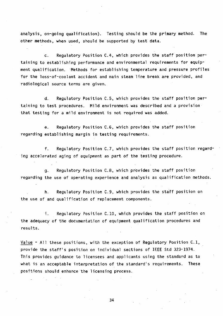
analysis, on-going qualification). Testing should be the primary method. The
other methods, when used, should be supported by test data.
c. Regulatory Position C.4, which provides the staff position per-
taining to establishing performance and environmental requirements for equip-
ment qualification. Methods for establishing temperature and pressure profiles
for the loss-of-coolant accident and main steam line break are provided, and
radiological source terms are given.
d. Regulatory Position C.5, which provides the staff position per-
taining to test procedures. Mild environment was described and a provision
that testing for a mild environment is not required was added.
e. Regulatory Position C.6, which provides the staff position
regarding establishing margin in testing requirements.
f. Regulatory Position C.7, which provides the staff position regard-
ing accelerated aging of equipment as part of the testing procedure.
g. Regulatory Position C.8, which provides the staff position
regarding the use of operating experience and analysis as qualification methods.
h. Regulatory Position C.9, which provides the staff position on
the use of and qualification of replacement components.
i. Regulatory Position C.10, which provides the staff position on
the adequacy of the documentation of equipment qualification procedures and
results.
Value - All these positions, with the exception of Regulatory Position C.1,
provide the staff's position on individual sections of IEEE Std 323-1974.
This provides guidance to licensees and applicants using the standard as to
what is an acceptable interpretation of the standard's requirements. These
positions should enhance'the licensing process.
34
Impact - With the possible exception of Regulatory Position C.1, the impact
should be minimal since the scope has not been changed from current practice.
The positions merely take established NRC provisions and relate them to appro-
priate sections of an endorsed voluntary consensus standard. Regulatory Posi-
tion C.1 will help to ensure that a common-cause failure that results in a
safety function not being performed is being addressed insofar as qualifica-
tion of equipment can prevent such a failure. The impact on each individual,
licensee will depend on the quality of equipment currently in use or intended
for use. The impact could be minimal since plant controls are a vital part of
keeping the plant in operation during plant electric power generation.
2. Regulatory Position C.4.d(3),,which is not part of NUREG-0588 but
which provides a source term for use in the qualification of certain accident-
monitoring instrumentation specified in Regulatory Guide 1.97, was added. This
instrumentation is for the measurement of designated variables whose maximum
value extends beyond the values predicted in the design basis accident analysis.
Value - The source term provided will standardize the radiation value for use
in the qualification of the high-level instrumentation specified in Regulatory
Guide 1.97 and will eliminate the necessity of determining source terms on a
case-by-case basis. This will enhance the licensing process.
Impact - There is no impact. The source term of Regulatory Position C.4.d(3)
merely provides an acceptable term for meeting the need expressed in Regula-
tory Guide 1.97 for a source term.
3. The Implementation Section was modified to be consistent with the
implementation of NUREG-0588 and the DOR Guidelines.
Value - The modified implementation is consistent with current requirements as
imposed by the Commission's Memorandum and Order CLI-80-21 dated May 23, 1980.
35

Impact - The impact should be minimal since, with the exception of Regulatory
Position C.1, no new requirements are imposed. The impact of Regulatory Posi-
tion C.1 on each individual licensee will depend on the quality of equipment
currently in use or intended for use. The impact could be minimal since plant
controls are a vital part of keeping the plant in operation during electric
power generation.
UNITED STATESNUCLEAR REGULATORY COMMISSION
WASHINGTON, D. C. 20555
OFFICIAL BUSINESSPENALTY FOR PRIVATE USE, $300
POSTAGE AND FEES PAID
U.S. NUCLEAR REGULATORYCOMMISSION
119406002001US NRC REGION IR J BORES631 PARK AVENUEREGION IKING OF PRUSSIA
I QPS I [SXR
PA 19406