draft geotechnical investigation report - … · 3 subsurface geotechnical conditions the...
TRANSCRIPT

Prepared for:
City of Clarence-Rockland
151-03483-00 Date: July 2015 WSP Canada Inc. 500 Greber Blvd, 3
rd Floor
Gatineau (Quebec) J8T 7W3 Phone: 819-243-2827 Fax: 819-243-2019 www.wspgroup.com
DRAFT GEOTECHNICAL INVESTIGATION REPORT
PROPOSED NEW SEWER INSTALLATION
CITY OF CLARENCE-ROCKLAND, ONTARIO

WSP Canada Inc. 500, Greber Blvd, 3rd Floor Gatineau (Québec) J8T 7W3 Phone: 819-243-2827 Fax: 819-243-2019 www.wspgroup.com
WSP Canada Inc. Adress line 1 Adress line 2 Adress line 3 www.wspgroup.com
July 28, 2015
Mr. Yves Rouselle, CET Assistant Director Infrastructure and Engineering City of Clarence-Rockland 415 Lemay St. Clarence Creek, ON K0A 1N0 Subject: Geotechnical Investigation Report – New Sewer Installation, Morris
Street, City of Clarence-Rockland, Ontario
Dear Mr. Rouselle:
We are pleased to submit our geotechnical investigation report for the above-noted project. A field investigation and laboratory testing program was conducted to assess soil and groundwater conditions at the site as input to design of the proposed new sewer installation.
This report includes our geotechnical recommendations for the proposed sewer installation, a site plan with borehole layout, and results from our field and laboratory investigation.
We trust that the report is straightforward and meets your current requirements.
Please contact us if you have any questions.
Yours truly,
Chris Hendry, M.Eng., P.Eng. Sr. Geotechnical Engineer Director Environment, Eastern Ontario

T A B L E O F C O N T E N T S
1 INTRODUCTION 1
1.1 Context 1
1.2 Site Description 1
1.3 Objectives and Limitations 1
2 SITE INVESTIGATION 3
2.1 Desktop Study 3
2.2 Field Investigation 3
2.3 Laboratory Testing Program 3
3 SUBSURFACE GEOTECHNICAL CONDITIONS 5
3.1 Topsoil 5
3.2 Fill 5
3.3 Sand and Silty Sand 5
3.4 Organic Soil 5
3.5 Silty Clay 6
3.6 DCPT Refusal 6
3.7 Groundwater 6

ii
4 RECOMMENDATIONS 7
4.1 General 7
4.2 Excavation and Dewatering 7
4.2.1 Excavation 7
4.2.2 Dewatering 8
4.3 Frost Penetration and Frost Protection 8
4.4 Seismic Site Classification 8
4.5 Grade Raise 8
4.6 Bedding Cover and Backfill 9
4.6.1 Bedding and Embedment 9
4.6.2 Cover 9
4.6.3 Backfill 9
4.7 Corrosion and Cement Type 10
5 GEOTECHNICAL PROJECT TEAM 11
A P P E N D I C E S
Appendix A Drawings
Appendix B Borehole Logs
Appendix C Laboratory Testing Results

1
Geotechnical Investigation– Proposed Sewer Installation, Morris Street 151-03483-00
1 INTRODUCTION
1.1 CONTEXT
SPL Consultants Limited (SPL) was retained by the City of Clarence-Rockland to conduct a geotechnical investigation as part the design and construction of a new sewer system connecting nine (9) townhouses to the city’s public sewer system on Morris Street, in Clarence-Rockland, Ontario. The Terms of Reference (TOR) for this investigation are outlined in WSP’s Proposal No. P15-11029-30 dated April 1, 2015 and subsequent project correspondence. The purpose of the geotechnical investigation was to obtain subsurface information at the site by means of exploratory boreholes. This report presents the findings of the investigation and provides comments and recommendations related to the geotechnical aspects of the project.
1.2 SITE DESCRIPTION
The site is located on Morris Street, approximately 130 m east of Lawrence Street, in the City of Clarence-Rockland, ON (see Figure No. 1). The site is located within the previously developed portion of the City, with low-rise residential development being present in the surrounding area. The site is relatively flat and is a combination of Morris Street (residential road) as well as the landscaped front lawns and driveways of the existing townhouse development.
1.3 OBJECTIVES AND LIMITATIONS
The current report was prepared at the request and for the sole use of the City of Clarence-Rockland according to the specific terms of the mandate given to WSP. The use of this report by a third party, as well as any decision based upon this report, is under this party’s sole responsibility. WSP may not be held accountable for any possible damages resulting from third party decisions based on this report. Furthermore, any opinions regarding conformity with laws and regulations expressed in this report are technical in nature; the report is not and shall not, in any case, be considered as a legal opinion. Information in this report is only valid for the borehole locations as described.

3
Geotechnical Investigation– Proposed Sewer Installation, Morris Street 151-03483-00
2 SITE INVESTIGATION
2.1 DESKTOP STUDY
Surficial geology maps indicate the area is underlain by alluvial deposits consisting of clay, silt, sand, gravel and organic remains overlying offshore marine deposits consisting of sensitive silty clay with minor sand deposits which overlies glacial till. Bedrock geology maps indicate the bedrock in the general area includes limestone, sandstone and shale of the Rockcliffe Formation.
2.2 FIELD INVESTIGATION
The field investigation was carried out on April 27, 2015 and included the drilling of two boreholes (BH15-1 and BH15-2) near the proposed sewer alignment. The boreholes were advanced using a track-mounted drill rig supplied and operated by Forage Geo Inc. of Grenville, Quebec. Boreholes BH15-1 and BH15-2 were advanced using hollow-stem auger drilling to a maximum depth of 6.1 m below the existing road surface and extended using Dynamic Cone Penetration Testing (DCPT) to a depth of up to 12.4 m below the existing road surface. The soil samples retrieved during drilling were logged and visually classified in the field by a member of SPL’s geotechnical staff. In-situ tests including Standard Penetration Testing (SPT) and shear vane testing were carried out at regular intervals. A monitoring well was installed in borehole BH15-2 to allow for subsequent measurement of stabilized groundwater levels and long-term groundwater monitoring at the site. The approximate borehole locations are shown in Drawing No. 2. The borehole logs are included in Appendix I of this report.
2.3 LABORATORY TESTING PROGRAM
Upon completion of drilling and in-situ testing, soil samples were returned to SPL’s laboratory for further examination, classification and testing. A laboratory testing program, which was carried out on selected representative soil samples included the determination of natural water content, grain size distribution, Atterberg limits (Plasticity) and chemical analyses of soil corrosivity. The results of natural water content tests are included on the relevant borehole logs in Appendix I. The results of determination of grain size distribution are summarized on the individual borehole logs and are presented in Appendix C. The results of Atterberg limits (plasticity) testing are summarized on the individual borehole logs and presented in Appendix C. Chemical testing to determine sulphate

4
Geotechnical Investigation– Proposed Sewer Installation, Morris Street 151-03483-00
content, chloride content, pH and resistivity was also carried out on selected soil samples obtained during drilling. The results of these tests are included in Appendix C.

5
Geotechnical Investigation– Proposed Sewer Installation, Morris Street 151-03483-00
3 SUBSURFACE GEOTECHNICAL CONDITIONS
The subsurface soil profile at the site generally consists of a layer of topsoil and fill material, overlying a layer of silty sand and sand, below which is sensitive silty clay. Specific descriptions of individual geological units are presented below.
3.1 TOPSOIL
A surficial layer of topsoil 225 mm in thickness was encountered in both boreholes (which were drilled on the lawns of the existing townhomes).
3.2 FILL
Underlying the topsoil in boreholes BH15-1 and BH15-2 is a layer of fill which ranged in consistency from silty sand to silty clay. This layer extended to a depth of 1.2 m below the existing surface elevation in borehole BH15-1 and to a depth of 0.8 m below the existing surface elevation in borehole BH15-2. One standard penetration test was carried out within this layer of upper fill gave an SPT ‘N’ value of 6 blows per 305 mm of penetration indicating a loose state of packing.
3.3 SAND AND SILTY SAND
Underlying the fill in both boreholes is a layer of native sand and silty sand. Standard penetration tests carried out within this layer gave SPT ‘N’ values which ranged from 3 to 18 blows per 305 mm of penetration indicating a very loose to compact consistency. This layer extended to a depth of 2.1 m below the existing ground surface in borehole BH15-1 and to a depth of 4.1 m below the existing ground surface in borehole BH15-2. A grain size distribution analyses from this unit is summarized below.
Table 1 Results of Particle Size Analysis - Sand
Borehole Sample
No. Depth Interval
(m below grade) Grain Size
Distribution Description
BH15-2 SS3 1.5 – 2.1 8% gravel, 84% sand; 8% fines
Sandy Silt
3.4 ORGANIC SOIL
Underlying the native sand in borehole BH15-1 is a layer of organic soil. Standard penetration tests carried out within this layer gave SPT ‘N’ values which ranged from the weight of the SPT hammer to

6
Geotechnical Investigation– Proposed Sewer Installation, Morris Street 151-03483-00
3 blows per 305 mm of penetration. This layer extended to a depth of 4.9 m below the existing surface elevation in borehole BH15-1. This layer was not encountered in borehole BH15-2. A selected sample of this material was submitted for testing to determine the percent organic matter by mass which was found to be 20.1 percent. The natural water content within the organic soil ranged from 140 to 215 percent.
3.5 SILTY CLAY
Underlying the silty sand in both boreholes is a layer of sensitive silty clay. This deposit generally consists of interlayered clay, silty clay and silt. Sand lenses may also be present. For simplicity this deposit is referred to in this report as silty clay (as this is the predominant soil type). The silty clay was proven through a combination of SPT sampling and shear vane testing to a depth of 6.1 m below the existing ground surface in borehole BH15-1 and to a depth of 5.5 m below the existing road surface in borehole BH15-2. In-situ soil strength was measured during drilling through a combination of SPT testing and in-situ shear vane testing at regular intervals. Standard penetration tests carried out within the silty clay gave SPT ‘N’ values ranging from 1 to 2 blows for 305 mm of penetration. Shear vane testing within the silty clay deposit yielded shear strengths between 50 kPa and 90 kPa indicating a stiff to very stiff consistency. Atterberg Limits (plasticity) testing was carried out on two samples of silty clay, the results of which are summarized below.
Table 2 Plasticity Test Results – Silty Clay
Borehole
No.
Sample No.
Depth Interval (m below
grade)
Moisture Content
(%)
Liquid Limit
(%)
Plastic Limit
(%)
Description
BH15-1 SS9 4.9 – 5.5 72 80 28
High Plasticity
Silty Clay
BH15-2 SS17 3.8 – 4.4 57 73 30 High Plasticity
Silty Clay
3.6 DCPT REFUSAL
Upon completion of augering, both boreholes were extended through Dynamic Cone Penetration (DCPT) Testing. In borehole BH15-1 DCPT refusal was encountered at 10.6 m below the existing ground surface. In borehole BH15-2 DCPT refusal was encountered at 12.4 m below the existing ground surface.
3.7 GROUNDWATER
A monitoring well was installed in borehole BH15-2 during the field investigation. Stabilized groundwater levels were read on May 8
th and May 20
th, 2015 (11 and 23 days after drilling,
respectively). Groundwater levels were found to be at 2.1 m below the ground surface on both occasions.

7
Geotechnical Investigation– Proposed Sewer Installation, Morris Street 151-03483-00
It should be noted that the groundwater levels can vary and are subject to seasonal fluctuations as well as fluctuations in response to major weather events.
4 RECOMMENDATIONS
4.1 GENERAL
It is understood that a new section of sewer will be installed to connect the existing townhouses to the existing City sewer system. It is understood that no significant changes will be made to the site grading. Based upon the borehole results the following geotechnical recommendations are provided.
4.2 EXCAVATION AND DEWATERING
4.2.1 EXCAVATION
Temporary excavations for typical sewer installations can be carried out using conventional hydraulic excavating equipment. Fill material can have, by its nature, a highly variable composition and could contain obstructions not encountered in the boreholes drilled at the site. All excavations should be carried out in accordance with the most recent Occupation Health and Safety Act (OHSA). For preliminary planning purposes, the soils encountered at the borehole locations may be classified as Type 3 soils above the groundwater table (approximately 2 m depth). The organic soils, loose silts and sands and sensitive silty clays should be classified as Type 4 soils below the groundwater table. If sufficient space does not exist to accommodate sloped excavations in these materials (which is likely the case given the amount of development in the area) then a temporary support system may be used. Temporary support for this type of project would typically include specially designed and constructed “trench boxes” but could also include interlocking sheet piles or similar shoring. Temporary support should be designed and installed by a contractor to both retain the existing soils and provide a safe working space, as well as to limit deflection and soil movement outside the work area to an acceptable level which will not cause damage to the existing structures and utilities. The soils at the site are a combination of silty clay, organic soils, silts and sands, some of which should be expected to have virtually no stand-up time and may behave as “flowing” soils if left unsupported below the water table. Caution should therefore be taken when moving trench boxes to prevent the sides of the excavation from being in an unsupported condition for any significant length of time. Similarly, caution should be exercised when excavating to ensure that the trench box fits tightly in the limits of the excavation, if not, the sides of the excavation may slough in. Where the trenches pass under the existing road, and allowance should be made for reconstructing the pavement adjacent to the trench boxes where sloughing or loosening occurs.

8
Geotechnical Investigation– Proposed Sewer Installation, Morris Street 151-03483-00
4.2.2 DEWATERING
The existing groundwater levels were found to be at approximately 2.1 m below the ground surface. Assuming the base of the excavation will be approximately 3.5 m to 4 m below the ground surface to accommodate the frost cover, pipe, bedding, etc. the base of the excavation could be 1.5 m to 2 m below the water table in a combination of silty sands, sands and organic soils. It is likely that seepage can be managed using pumping from closely spaced and properly filtered sumps in the base of the excavation. In the event the groundwater is higher at the time of construction then an active dewatering system, such as pumping from well points, may be required to maintain a dry base and prevent heaving and disturbance of the excavation base. The soils present in the boreholes (silty sand, sand, organic soil and silty clay) are expected to be susceptible to disturbance due to construction activities and groundwater piping. If appropriate groundwater control is not in place during construction then disturbance of the excavation base may occur. In addition, construction activities in saturated soils can also loosen the trench base. Either condition could result in a requirement for removal and replacement of the subgrade with imported granular soil. A Permit to Take Water (PTTW), issued by the Ontario Ministry of the Environment (MOE) is required if the dewatering system results in a water taking of more than 50,000 l/day. The quantity of groundwater to be pumped will depend no only on soil types and groundwater levels, but on the size and depth of excavation which will remain open at a given time. If the excavation is kept very small and completed in sections, it is likely that the pumping will be less than 50,000 l/day. It should be noted, however, that the MOE requires 90 days to process and review a PTTW application. This process has the potential to cause major delays if unforeseen groundwater conditions are encountered, or if very large temporary excavations are used. For this reason it may be beneficial for the City to obtain a PTTW prior to construction so as to avoid major delays or constraining the contractor’s activities once construction has started. The presence of the new utility trench has the potential to permanently lower the groundwater table (by providing a drainage path) which could result in long-term settlement of the silty clay. It is recommended that clay cut-offs extending the full depth and width of the trench be installed to prevent the new utility trench from acting as a drain.
4.3 FROST PENETRATION AND FROST PROTECTION
Water bearing services should maintain a minimum burial depth of 2.4 m. If this depth of soil cover cannot be accommodated then the services may be insulated as an alternative to deep burial.
4.4 SEISMIC SITE CLASSIFICATION
The site can be classified as Class D for seismic site response.
4.5 GRADE RAISE
It is understood that no significant grade raise is anticipated for the site. Grade raises have the potential to cause settlement of the underlying clay and organic soils, and should they be required, WSP should provide additional review and consultation.

9
Geotechnical Investigation– Proposed Sewer Installation, Morris Street 151-03483-00
4.6 BEDDING COVER AND BACKFILL
4.6.1 BEDDING AND EMBEDMENT
Flexible pie bedding and embedment material should include a minimum of 300 mm of OPSS Granular “A” sand and gravel. The bedding and embedment material should extend a minimum of 300 mm above the pipe as per OPSD 802.010. Bedding for rigid pipes should include OPSS Granular A from a depth of 300 mm below the invert of the pipe to the springline of the pipe. Bedding and embedment material should be compacted to 95% of Standard Proctor Maximum Dry Density (SPMDD). All trench bases should be reviewed by WSP prior to placement of bedding material. Where loose, wet or disturbed soils are encountered in the base of the trench it may be necessary to excavate and replace the soil with additional granular fill or bedding.
4.6.2 COVER
Pipe cover should extend to 300 mm above the top of pipe. Cover for rigid pipe may include either Granular A or B with a maximum grain size of 26.5 mm (as per OPSS 401). Cover material should be compacted to 95% SPMDD. Care should be taken when compacting overtop of the pipe so as to protect the pipe from damage due to equipment and compaction.
4.6.3 BACKFILL
All backfill should consist of suitable portions of the existing soils or approved imported fill material. In paved areas, to the extent possible, backfill in the frost zone should be made to match the existing soils exposed in the excavation to minimise the potential for differential frost heave. Portions of the existing fill materials as well as the sandy soils may be salvageable for reuse as backfill. The organic soils encountered in BH15-1 are not considered suitable for reuse as trench backfill and should be discarded. It is important to note that soils present below the water table may require moisture conditioning (drying) prior to reuse. It is recommended that the soils be reviewed as excavated to confirm suitability for reuse as backfill. Both native and imported soils should be approved by the contract administrator prior to reuse. All backfill should be free from frozen lumps, cinders, ash, organic matter, rock and boulders over 150 mm in diameter or other deleterious material. Backfill should be placed in lifts not exceeding 300 mm loose thickness and compacted to 95% SPMDD. Failure to properly moisture condition the backfill material will likely lead to difficulty in achieving the required compaction.
10
Geotechnical Investigation– Proposed Sewer Installation, Morris Street 151-03483-00
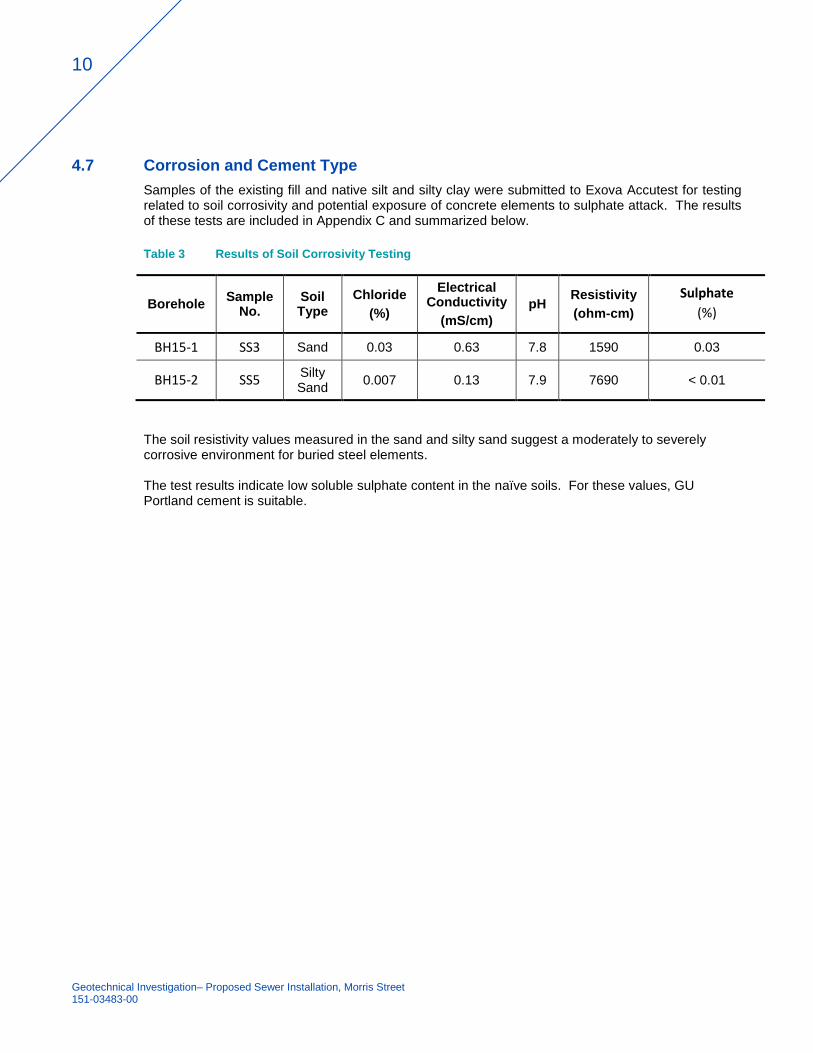
4.7 Corrosion and Cement Type
Samples of the existing fill and native silt and silty clay were submitted to Exova Accutest for testing related to soil corrosivity and potential exposure of concrete elements to sulphate attack. The results of these tests are included in Appendix C and summarized below.
Table 3 Results of Soil Corrosivity Testing
Borehole Sample
No. Soil Type
Chloride
(%)
Electrical Conductivity
(mS/cm)
pH Resistivity
(ohm-cm)
Sulphate
(%)
BH15-1 SS3 Sand 0.03 0.63 7.8 1590 0.03
BH15-2 SS5 Silty Sand
0.007 0.13 7.9 7690 < 0.01
The soil resistivity values measured in the sand and silty sand suggest a moderately to severely corrosive environment for buried steel elements. The test results indicate low soluble sulphate content in the naïve soils. For these values, GU Portland cement is suitable.

Appendix A
DRAWINGS

!
CLARENCE-ROCKLAND
Lac Dollard-des-Ormeaux
COUN
TY RO
AD 17
CA
RO
N S
TR
EE
T
LAURIE
R S
TREET
ST
JE
AN
ST
RE
ET
PROPOSED NEW SEWER - MORRIS STREET
For the City of Clarence-Rockland
SITE LOCATION MAP
1
FILE. NO.:10001783 F1PROJECT: 10001783
DATE: MAY 2015
FIGURE
200 0 200100 Metres
.1:20000SCALE:
Data Source: Ministry of Natural Resources,Ontario Base Mapping, March 2014.
LEGEND
! APPROXIMATE SITE LOCATION

PROPOSED NEW SEWER - MORRIS STREET
For the City of Clarence-Rockland
BOREHOLE LOCATION MAP
2
FILE. NO.:10001783 F2PROJECT: 10001783
DATE: MAY 2015
FIGURE
10 0 105 Metres
.1:800SCALE:
Data Source: Ministry of Natural Resources,Ontario Base Mapping, March 2014.Imagery, BING.
LEGEND
@A APPROXIMATE BOREHOLE LOCATION AND DESIGNATIONBH15-1

Appendix B
BOREHOLE LOGS

TOPSOIL - 225 mm
SILTY SANDtrace gravel, trace roots, dark brown, moist (FILL)
SANDdark brown, trace gravel, trace silt, moist, loose
Organic Soilwith wood fragments, dark brown, damp
- some roots and trace gravel- light brown- fine fiberous
SILTY CLAYgrey, wet, stiff to very stiff
- Augering ended at 6.1 m. Borehole continued byDCPT testing.
SILTY CLAY(Infered by DCPT results)
End of Borehole
Notes:1) Borehole was dry upon completion of augering2) DCPT refusal at 10.6 m below surface level
0.2
1.2
2.1
4.9
6.1
10.6
GSA SS3:GRAVEL: 7.8%SAND: 84.1%SILT AND CLAY: 8.1%
AL SS9B:LL: 80PL: 28PI: 52Su= 86 kpa; S = 5.7
Su= 90 kpa; S = 2.7
SS1ASS1B
SS2
SS3
SS4
SS5
SS6
SS7
SS8
SS9
VANE
VANE
7
6
3
3
3
3
2
0
1
29.613.5
20.4
29.4
21.9
140
214.6
155.6
97.6
BOREHOLE NO. BH15-1
PROJECT NAME: NEW SEWER SYSTEM INSTALLATION
CONEPENETRATION
BOREHOLE TYPE: 203 mm HOLLOW STEM AUGER SUPERVISOR: DW
STRATIGRAPHIC DESCRIPTION
ST
RA
TIG
RA
PH
Y
"N" VALUE
50 75
WW
302010
WATERCONTENT %
GROUND ELEVATION: NOT DETERMINED
DATE COMPLETED: Apr 27, 2015
REMARKS
REVIEWER: CH
L
DEPTH(m)
PROJECT NO.: 10001783
P
SAMPLE
25
SHEARSTRENGTH
MONITORDETAILS
CLIENT: CITY OF CLARENCE-ROCKLAND
PAGE 1 of 1
0.0
1.0
2.0
3.0
4.0
5.0
6.0
7.0
8.0
9.0
10.0
11.0
12.0
13.0
14.0
15.0
MONITORDETAILS
TY
PE
N V
ALU
E
% W
AT
ER
% R
EC
OV
ER
Y
RQ
D (%
)
WS
P G
EO
LOG
IC (
ME
TR
IC)
DY
NA
MIC
CO
NE
M
OR
RIS
_ST
RE
ET
.GP
J W
SP
_EN
V_V
1.G
DT
5/
21/1
5
140
214.6
155.6
100

TOPSOIL - 225 mm
SILTY SAND TO SILTY CLAYwith wood fragments, brown to grey, moist (FILL)
SILTY SANDbrown, moist, loose
- grey- wet- compact
- loose
SILTY CLAYgrey, wet, stiff to very stiff
- Augering ended at 5.5 m. Borehole continued byDCPT testing.
SILTY CLAY(Infered by DCPT results)
GLACIAL TILL(Infered by DCPT results)
End of Borehole
Notes:1) Water level was at 2.7 m below surface level uponcompletion of augering2) DCPT refusal at 12.4 m below surface level3) 50mm dia. monitoring well was installed at 3.8 mbelow surface level4) Date Depth-groundwater--------------------------------------------------May 8, 2015 2.1 mMay 20, 2015 2.1 m
0.2
0.8
4.1
5.5
11.6
12.4
AL SS6B:LL: 73PL: 30PI: 43
SS1ASS1B
SS2
SS3
SS4
SS5
SS6
VANE
VANE
5
9
5
18
8
2
43.414.1
8.3
11.3
19.8
22.7
56.5
BOREHOLE NO. BH15-2
PROJECT NAME: NEW SEWER SYSTEM INSTALLATION
CONEPENETRATION
BOREHOLE TYPE: 203 mm HOLLOW STEM AUGER SUPERVISOR: DW
STRATIGRAPHIC DESCRIPTION
ST
RA
TIG
RA
PH
Y
"N" VALUE
50 75
WW
302010
WATERCONTENT %
GROUND ELEVATION: NOT DETERMINED
DATE COMPLETED: Apr 27, 2015
REMARKS
REVIEWER: CH
L
DEPTH(m)
PROJECT NO.: 10001783
P
SAMPLE
25
SHEARSTRENGTH
MONITORDETAILS
CLIENT: CITY OF CLARENCE-ROCKLAND
PAGE 1 of 1
0.0
1.0
2.0
3.0
4.0
5.0
6.0
7.0
8.0
9.0
10.0
11.0
12.0
13.0
14.0
15.0
MONITORDETAILS
TY
PE
N V
ALU
E
% W
AT
ER
% R
EC
OV
ER
Y
RQ
D (%
)
WS
P G
EO
LOG
IC (
ME
TR
IC)
DY
NA
MIC
CO
NE
M
OR
RIS
_ST
RE
ET
.GP
J W
SP
_EN
V_V
1.G
DT
5/
21/1
5
100

Appendix C
LABORATORY TESTING RESULTS


EXOVA ENVIRONMENTAL ONTARIO Certificate of Analysis
Client: SPL Consultants Ltd. 146 Colonnade Rd., Unit 17 Ottawa, ON K2E 7Y1Attention: Ms. Wendy McLaughlinPO#: Invoice to: SPL Consultants Ltd.
Report Number: 1507395 Date Submitted: 2015-05-07Date Reported: 2015-05-14Project: 10001783COC #: 173001
Lab I.D.Sample MatrixSample TypeSampling DateSample I.D.
Group Analyte MRL Units Guideline
7.8
0.031
0.63
1590
0.03
7.9
0.007
0.13
7690
<0.01
20.1
%0.01 SO4
General Chemistry
ohm-cm1 Resistivity mS/cm0.05 Electrical Conductivity %0.002 Cl 2.0 pH
Agri. - Soil %0.1 Organic Matter (@440C)
1172464Soil
2015-04-27BH 15-1 SS8
1172463Soil
2015-04-27BH 15-2 SS5
1172462Soil
2015-04-27BH 15-1 SS3
Group Analyte MRL Units Guideline
Lab I.D.Sample MatrixSample TypeSampling DateSample I.D.
Page 2 of 3146 Colonnade Rd. Unit 8, Ottawa, ON K2E 7Y1
All analysis completed in Ottawa, Ontario (unless otherwise indicated by ** which indicates analysis was completed in Mississauga, Ontario).Results relate only to the parameters tested on the samples submitted.Methods references and/or additional QA/QC information available on request.
Guideline = * = Guideline Exceedence MRL = Method Reporting Limit, AO = Aesthetic Objective, OG = Operational Guideline, MAC = Maximum Acceptable Concentration, IMAC = Interim Maximum Acceptable Concentration, STD = Standard, PWQO = Provincial Water Quality Guideline, IPWQO = Interim Provincial Water Quality Objective, TDR = Typical Desired Range

EXOVA ENVIRONMENTAL ONTARIO Certificate of Analysis
Client: SPL Consultants Ltd. 146 Colonnade Rd., Unit 17 Ottawa, ON K2E 7Y1Attention: Ms. Wendy McLaughlinPO#: Invoice to: SPL Consultants Ltd.
Report Number: 1507395 Date Submitted: 2015-05-07Date Reported: 2015-05-14Project: 10001783COC #: 173001
QC % Rec
BlankAnalyte
QC Summary
QCLimits
287194Run No: Analysis Date: 2015-05-11 Method: C CSA A23.2-4B
101 90-110Cl <0.002 %
287270Run No: Analysis Date: 2015-05-11 Method: Cond-Soil
85-115Electrical Conductivity
90-110pH
Resistivity
287356Run No: Analysis Date: 2015-05-12 Method: C SM4500-SO4--D
129 70-130SO4 <0.01 %
287399Run No: Analysis Date: 2015-05-14 Method: Ag Soil
Organic Matter (@440C)
Page 3 of 3146 Colonnade Rd. Unit 8, Ottawa, ON K2E 7Y1
All analysis completed in Ottawa, Ontario (unless otherwise indicated by ** which indicates analysis was completed in Mississauga, Ontario).Results relate only to the parameters tested on the samples submitted.Methods references and/or additional QA/QC information available on request.
Guideline = * = Guideline Exceedence MRL = Method Reporting Limit, AO = Aesthetic Objective, OG = Operational Guideline, MAC = Maximum Acceptable Concentration, IMAC = Interim Maximum Acceptable Concentration, STD = Standard, PWQO = Provincial Water Quality Guideline, IPWQO = Interim Provincial Water Quality Objective, TDR = Typical Desired Range