draft - for committee use only
TRANSCRIPT

DRAFT - For Committee Use Only
1 of 44 Appendix Q XX-XX-XX X.doc
Draft for SCAST Ballot
Agenda Item 620-292
Revisions to App Q and R to Coordinate with New API 625 Standard
Revision: 2c (Changes from revision 0 are shaded in various colors)
Date: 2c Dec 10, 2009 – various improvements, from NFPA, chair suggestions +Dec 10 mtg1e July 27, 2009 - Response to Challa comments on EN 10025 and 10028 materials1d July 17, 2009 – Change “shoulds” to something else in all (four) locations& deleted remaining references to A131-CS, added “in.” in Table R-61c April 9, 2009 - Addition of EN 10025 and 10028 materialsRev 1a and 1b changes through Jan. 15, 2009
Handled by: Doug Miller – RTTG ChairChicago Bridge and Iron CompanyPlainfield, IL 60544-8984Telephone: 815-439-6522Email: [email protected]
Impact: These 620 changes with the new API 625 standard (and ACI 376 when complete) will equip American standards to address up to date double and full containment tank systems in addition to the single containment tank systems previously covered.
Brief Summary of Changes:1. Different terminology was required to address each part of single, double and full containment tank systems. The
terms “primary component” and “secondary component” have been eliminated. These old terms conflict with new terms “primary liquid container” and “secondary liquid container”. Instead we just list in Q.2.1 and Q.2.3 the components requiring “product temperature materials” and “atmospheric temperature materials”.
2. Changes in App R for the most part parallel those in App Q. Therefore the Task Group will address ballot comments made to Q in R as well where the wording is the same.
3. Section Q.3.8 (and R.3.9) on load combinations is coordinated better with base section 5.4.2 as well as expanded to address secondary liquid containers.
4. Some reorganizing was inevitable to accomplish the needed changes. Some content was moved from 620 into 625 where appropriate and some other content was moved within App Q and R.
5. A very few changes in content are proposed at this time that were not related to API 625 and double/full containment. See 316SS grades in Table Q-3, flux core weld consumables in Q.4, piping NDE in Q.5.7 and adjustment in test water height in Q.6.1.
6. Coverage of double roof tanks is retained as has been the case in past editions of API 620. This remains a distinctive of the API stds in contrast to EN14620 and BS7777.
7. EN 10028 for liquid containers and EN 10025 materials for atmospheric temperature materials have been added.

DRAFT - For Committee Use Only
2 of 44 Appendix Q XX-XX-XX X.doc
PROPOSED TEXTAPI 620 BASE DOCUMENT
Section 2
EN 10025 xx Hot Rolled Products of Structural SteelsEN 10028 Flat Products made of Steels for Pressure Purposes
xx European Committee for Standardization, Management Centre: rue de Stassart, 36 B-1050 Brussels, Belgium.
__________________________________________________________________________________________________
APPENDIX QLOW-PRESSURE STORAGE TANKS FOR LIQUEFIED HYDROCARBON
GASES AT -325°F OR WARMER
Q.1 ScopeQ.1.1 GENERAL
The provisions in this appendix form a guide for the materials, design, and fabrication of tanks to be used for the storage of liquefied ethane, ethylene, and methane.
This appendix together with the basic sections of API 620 provides requirements for the materials, design, and fabrication of the metallic portions of a refrigerated tank system. The requirements for a basic API Std 620 tank apply to primary and secondary liquid containers, refrigerated temperature roofs, warm vapor containers, purge gas containers and their appurtenances except where they are superseded by any requirements of this appendix. Requirements for the complete tank system, of which the metallic components are a part, are found in API 625. All other requirements for an API Std 620 tank shall apply.
Q.1.2 PIPING LIMITATIONS
Piping limitations given in API 620 1.3.2 are superseded by API 625, section 1.6.
A refrigerated tank may be a single-wall insulated tank or a double-wall tank that consists of an inner tank for storing the refrigerated liquid and an outer tank that encloses an insulating space around the inner tank. A double-wall tank is a composite tank; the outer tank is not required to contain the product of the inner tank. In a double-wall tank, differences in materials, design, and testing exist between the inner and outer tanks.
Q.1.3 PRESSURE RANGE
The provisions in this appendix apply to all design pressures from -0.25 psig to +7.00 psig. within the scope of this standard.
Q.1.4 TEMPERATURE
The provisions in this appendix apply to design metal temperatures encountered in the storage of liquefied hydrocarbon gases, but they do not apply to temperatures lower than – 270°F of -325°F or warmer.
Q.1.5 DEFINITIONS
The definitions of the following specialized terms used in this appendix are found in API 625:Q.1.5.1 Refrigerated Tank SystemQ.1.5.2 Single Containment Tank SystemQ.1.5.3 Double Containment Tank SystemQ.1.5.4 Full Containment Tank System
RTTG has taken position that it would be better to not exclude application to things like LOX/LIN storage. Compressed Gas Association has verified that they have good experience with this.

DRAFT - For Committee Use Only
3 of 44 Appendix Q XX-XX-XX X.doc
Q.1.5.5 Primary Liquid ContainerQ.1.5.6 Secondary Liquid ContainerQ.1.5.7 Warm vapor container Q.1.5.8 Purge gas containerQ.1.5.9 Refrigerated temperature roofQ.1.5.10 Design PressureQ.1.5.11 Annular SpaceQ.1.5.12 Suspended deckQ.1.5.13 Design Metal Temperature
Q.1.4 PRIMARY COMPONENTS
Q.1.4.1 In general, primary components include those components that may be stressed to a significant level, those whose failure would permit leakage of the liquid being stored, those exposed to a refrigerated temperature between – 60°F and –270°F, and those that are subject to thermal shock. The primary components shall include, but will not be limited to, the following parts of a single-wall tank or of the inner tank in a double-wall tank: shell plates; bottom plates; roof plates; knuckle plates; compression rings; shell stiffeners; and manways and nozzles including reinforcement, shell anchors, pipe, tubing, forgings, and bolting.
Q.1.4.2 When roof plates, knuckle plates, compression rings, and manways and nozzles including reinforcement are primarily subjected to atmospheric temperature, the rules in Q.2.3 shall govern.
Q.1.5 SECONDARY COMPONENTS
In general, secondary components include those components that will not be stressed to a significant level by the refrigerated liquid, those whose failure will not result in leakage of the liquid being stored, those exposed to product vapors, and those that have a design metal temperature of – 60°F or higher.
Q.2 MaterialsThe materials requirements are based on the storage of refrigerated products at the design metal temperature.
Q.2.1 PRIMARY COMPONENTS PRODUCT TEMPERATURE MATERIALS
Materials for primary the following metallic components (including their penetrations, piping, anchors, stiffeners and attachments) shall be selected from Table Q-1 and shall comply with the requirements of Q.2.2: and Table Q-1:
a) Primary Liquid Containers
b) Secondary Liquid Containers
c) Refrigerated Temperature Roofs
(This includes inner roofs of double roof tanks, and single roofs of tanks with external roof insulation)
d) Thermal distance pieces connecting cold piping to warm vapor or purge gas containers.
e) For full containment tank systems; Portions of warm vapor containers that may experience cold gas flows in the event of primary liquid container leakage.
f) Metallic Suspended Decks for Insulation
Table Q-1—ASTM Standards for Product Temperature Materials for Primary ComponentsPlates and Structural Members Piping, Piping Fittings
and TubingForgings Bolting

DRAFT - For Committee Use Only
4 of 44 Appendix Q XX-XX-XX X.doc
A 353 (See note 1)A 553, Type 1 (see note 1)A 645 grade AA 645 grade B
A333,Grade 8 (see note 2)A334,Grade 8 (see note 2)B444 (UNS-N06625), Gr 1B444 (UNS-N06625), Gr 2B619 (UNS N-10276) (see notes 3 & 6)B622 (UNS-N10276)
A522
A 240, Type 304A 240, Type 304L
A 240, Type 316A 240, Type 316L
A240, Type 201LN (UNS-S20153)
A213, Grade TP304A213, Grade TP304LA312, Grade TP304 (see note 3)A312, Grade TP304L (see note 3)A403, Grade WP304A403, Grade WP304LA213, Grade TP316A213, Grade TP316LA312, Grade TP316 (see note 3)A312, Grade TP316L (see note 3)A403, Grade WP316A403, Grade WP316L
A182, Grade F304A182, Grade F304L
A182, Grade F316A182, Grade F316L
A320, Grades B8, B8C, B8M and B8T
B 209, Alloy 3003-0 (see note 5B 209, Alloy 5052-0 (see note 5)B 209, Alloy 5083-0 (see note 5)B 209, Alloy 5086-0 (see note 5)B 209, Alloy 5154-0 (see note 5)B 209, Alloy 5456-0 (see note 5)B 221, Alloy 6061-T4 and T6B 308, Alloy 6061-T2 and T6
B210, Alloy 3003-0B210, Alloy 3003-H112B210, Alloy 5052-0B210, Alloy 5086-0B210, Alloy 5154-0B241, Alloy 5052-0 B241, Alloy 5083-0B241, Alloy 5086-0B241, Alloy 5454-0B241, Alloy 5456-0
B247, Alloy 3003-H112B247, Alloy 3003-H112ModB247, Alloy 6061-T6
F468 B211,Alloy 6061-T6
Notes:1. When pressure parts are made of ASTM A 353 or A 553 material or nickel alloy, pipe flanges or pipe may be austenitic stainless steel of a type that cannot be hardened by heat treatment. Pipe flanges or pipe may be welded to nozzle necks of the pressure part material if the butt weld is located more than a distance equal to the rt measured from the face of the reinforcement where r = inside radius of the nozzle neck, in in., and t = thickness of the nozzle neck, in in. The design of the nozzle neck shall be based on the allowable stress value of weaker material. Note void.2. Seamless piping and tubing only.3. Purchased welded pipe shall be without the addition of filler metal using a process permitted by the named ASTM specification and shall be tested hydrostatically or by eddy current to ASTM requirements.4. Impact test of welds shall be made for the welding procedure when required by Q.4.3.5. ASTM B 221 structural sections are also permitted.6. Pipe conforming to ASTM B 619 and note 3 of this table may be used in diameters exceeding the 8-in. limit stated in B 619 when approved by purchaser. Further, for this pipe over 8-in. diameter, the addition of filler metal is permitted.
Q.2.2 IMPACT TEST REQUIREMENTS FOR PRODUCT TEMPERATURE MATERIALS PRIMARY COMPONENTS
Note 1 not needed since Q.2.5.2 covers this subject
DRAFT - For Committee Use Only
5 of 44 Appendix Q XX-XX-XX X.doc
Q.2.2.1 All primary components of 9% or 5% nickel steel shall be impact tested in accordance with Q.2.2.2 through Q.2.2.4. Impact testing is not required for primary components of austenitic stainless steel, nickel alloy, and aluminum materials. Welds in high-alloy (austenitic) stainless steel shall be impact tested if required by Q.4.3.
Q.2.2.2 Impact testing of plates, including structural members made of plate, shall comply with the following:
a. Impact test specimens shall be taken transverse to the direction of final plate rolling.
b. Charpy V-notch specimens shall be cooled to a temperature of – 320°F for A 353, A 553, and A 645 steels for impact testing.
b. For ASTM A 353, and A 553 steels, Charpy V-notch specimens shall be cooled to a temperature of – 320°F.
Note: This temperature is selected to be consistent with the standard requirements of the ASTM specifications. The temperature of –320°F also provides a convenient and safe medium (liquid nitrogen) for cooling; for testing techniques, see ASTM A 370. For ethylene and ethane service, the test temperature of – 220°F is also acceptable.
c. For ASTM A 645 steels, Charpy V-notch specimens shall be cooled to a temperature of – 320°F unless the designmetal temperature is -155°F or warmer, in which case the specimens may be cooled to the alternate temperature of -220°F.
d. The transverse Charpy V-notch impact values shall conform to Table Q-2.
e. Each test shall consist of three specimens, and each specimen shall have a lateral expansion opposite the notch of not less than 0.015 in. (15 mils) as required by ASTM A 353, A 553, and A 645.
f. Retests shall be in accordance with ASTM A 353, A 553, and A 645.
Q.2.2.3 Impact testing of structural members shall comply with the following:
a. For each different shape in each heat-treatment lot, one set of three specimens taken in the longitudinal direction from the thickest part of each shape shall be tested. If the heat-treatment lot consists of shapes from several ingots, tests shall be conducted on the various shapes of each ingot.
b. Charpy V-notch specimens shall be cooled to a temperature of – 320°F (see Q.2.2.2, item b) for A 353, A 553, and A 645 grade A or B steels for impact testing.
c. The longitudinal Charpy V-notch impact values shall conform to Table Q-2.
d. Each test shall consist of three specimens, and each specimen shall have a lateral expansion opposite the notch of not less than 0.015 in. (15 mils) as required by ASTM A 353, A 553, and A 645.
e. Retests shall be in accordance with ASTM A 353, A 553, and A 645.
Q.2.2.4 Impact testing of forgings, piping, and tubing shall comply with the following:
a. Impact test specimens shall be taken from each heat included in any heat-treatment lot.
b. Charpy V-notch specimens shall be cooled to a temperature of – 320°F (see Q.2.2.2, item b) for A 522, A 333 (Grade 8), and A 334 (Grade 8) steels for impact testing.
c. The minimum Charpy V-notch impact values shall conform to the longitudinal values in Table Q-2.
d. Each test shall consist of three specimens, and each specimen shall have a lateral expansion opposite the notch of not less than 0.015 in. (15 ml) as required by ASTM A 522, A 333, (Grade 8), and A 334 (Grade 8).
e. Retests shall be in accordance with ASTM A 522, A 333 (Grade 8), and A 334 (Grade 8).
DRAFT - For Committee Use Only
6 of 44 Appendix Q XX-XX-XX X.doc
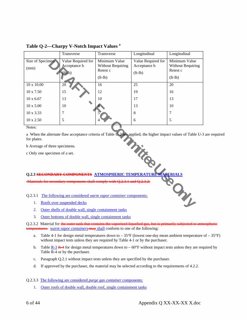
Table Q-2—Charpy V-Notch Impact Values a
Transverse Transverse Longitudinal Longitudinal
Size of Specimen
(mm)
Value Required for Acceptance b
(ft-lb)
Minimum Value Without Requiring Retest c
(ft-lb)
Value Required for Acceptance b
(ft-lb)
Minimum Value Without Requiring Retest c
(ft-lb)
10 x 10.00
10 x 7.50
10 x 6.67
10 x 5.00
10 x 3.33
10 x 2.50
20
15
13
10
7
5
16
12
10
8
5
4
25
19
17
13
8
6
20
16
13
10
7
5
Notes:
a When the alternate flaw acceptance criteria of Table U-2 are applied, the higher impact values of Table U-3 are required for plates.
b Average of three specimens.
c Only one specimen of a set.
Q.2.3 SECONDARY COMPONENTS ATMOSPHERIC TEMPERATURE MATERIALS
Materials for secondary components shall comply with Q.2.3.1 and Q.2.3.2:
Q.2.3.1 The following are considered warm vapor container components:
1. Roofs over suspended decks
2. Outer shells of double wall, single containment tanks
3. Outer bottoms of double wall, single containment tanks
Q.2.3.2 Material for the outer tank that contains the vaporized liquefied gas, but is primarily subjected to atmospheric temperatures warm vapor containers may shall conform to one of the following:
a. Table 4-1 for design metal temperatures down to – 35°F (lowest one-day mean ambient temperature of – 35°F) without impact tests unless they are required by Table 4-1 or by the purchaser.
b. Table R-3 R-4 for design metal temperatures down to – 60°F without impact tests unless they are required by Table R-4 or by the purchaser.
c. Paragraph Q.2.1 without impact tests unless they are specified by the purchaser.
d. If approved by the purchaser, the material may be selected according to the requirements of 4.2.2.
Q.2.3.3 The following are considered purge gas container components:
1. Outer roofs of double wall, double roof, single containment tanks

DRAFT - For Committee Use Only
7 of 44 Appendix Q XX-XX-XX X.doc
2. Outer shells of double wall, double roof, single containment tanks
3. Outer bottoms of double wall, double roof, single containment tanks
Q.2.3.4 Material for the•••
outer tank that does not contain the••••••••••••••••••••••••••••••
vaporized liquefied••••••••••••••••••
gas purge gas containers may shallconform to any one of the approved materials listed in Table 4-1. Consideration of the design metal temperature is not required if the actual stress in the outer tank does not exceed one-half the allowable tensile design stress for the material.
Q.2.4 STRUCTURAL SHAPES
Structural shapes of 9% and 5% nickel steel may be furnished to the chemical and physical requirements of ASTM A 353, A 553, or A 645. Physical tests shall be in accordance with the requirements of ASTM A 6.
Q.2.5 PIPING, TUBING, AND FORGINGS
Q.2.5.1 Material used for piping, tubing, and forgings shall be compatible in welding, strength, and thermal expansion coefficient with the tank shell material. In addition to the specific requirements of this appendix, all piping within the limitations of Q.1.2 shall fulfill the minimum material requirements of ASME B31.3. Q.2.5.2 Except as allowed by Q.2.5.3 and Q.2.5.4, piping, tubing, and forgings used for openings within a distance of 2 x sqrt(dxtn) from the tank wall shall be compatible in welding, strength, and thermal expansion coefficient with the tank wall material (d and tn are defined in Figure 5-7).Q.2.5.3 Nickel alloy material B 444 (UNS-N06625), B 622 and B 619 (UNS-N10276) in Table Q-1 may be used for piping and tubing as a substitute for A 333, Grade 8 or A 334, Grade 8 for openings through 9% Ni (A 353, A 553) and 5% Ni (A 645) storage tanks, providing these materials meet the applicable requirements in this appendix and are not used for reinforcement.Q.2.5.4 300 series stainless steel materials in Table Q-1 may be used for piping and tubing for openings through 201LN storage tanks, providing these materials meet the applicable requirements in this appendix and are not used for reinforcement.
Q.3 DesignQ.3.1 GENERAL
Design considerations shall be as specified in API 625, section 6, “Design and Performance Criteria” together with the additional provisions of this section Q.3.
Q.3.2 DENSITY OF LIQUID STORED
The density of the liquid stored shall be its maximum density within the range of design temperatures.
The weight of liquid stored shall be assumed to be the maximum weight per ft3 of the specified liquid within the range of operating temperatures, but in no case shall the assumed minimum weight be less than 29.3 lbf/ft3 for methane, 34.21 lbf/ft3 for ethane, and 35.5 lbf/ft3 for ethylene.
Q.3.2 DESIGN METAL TEMPERATURE
The design metal temperature of each component exposed to the liquid or vapor being stored shall be the lower of the temperatures specified as follows:
a. The design metal temperature of the components of the single-wall tank or the inner tank of a double-wall tank shall be the minimum temperature to which the tank contents shall be refrigerated, including the effect of subcolony at reduced pressure.
API 625 section 6.3.6 now covers Design Temperature.
First sentence of Q.2.5.1 is redundent w/ Q.2.5.2. Its presence in current published std is an editorial error from the merging of past agenda items 620-270 and 620-272. Both of these were handlled by DGM.
DRAFT - For Committee Use Only
8 of 44 Appendix Q XX-XX-XX X.doc
b. The design metal temperature of the secondary components shall be the lower of the minimum atmospheric temperature conditions (see 4.2.1) and the vaporized liquefied gas temperature, if the components are in contact with the vapor. The effectiveness of the insulation in keeping the metal temperature above the minimum atmospheric or refrigerated temperature shall be considered.
Q.3.3 ALLOWABLE DESIGN STRESSES
Q.3.3.1 The maximum allowable design stresses for the materials outlined in Q.2.1 shall be in accordance with Table Q-3.
Q.3.3.2 The values for the allowable design tensile stress given in Table Q-3 for materials other than bolting steel are the lesser of (a) 33-1/3% of the specified minimum ultimate tensile strength for the material or (b) 66-2/3% of the specified minimum yield strength, but they are 75% of the specified minimum yield strength for the stainless steel, nickel alloy, and aluminum materials. Allowable test stresses are based on the limitation of Q.6.1.3.
Q.3.3.3 For the base materials associated with Table Q-3, notes a and b; if(a) the weld filler metal has an unspecified yield strength, or (b) the weld filler metal has specified minimum yield or ultimate tensile strength below the specified minimums for the base metal, or(c) the welding procedure qualification test shows the deposited weld metal tensile strength is lower than the specified minimum ultimate tensile strength of the base metal,
then the allowable stresses shall be based on the weld metal and heat affected zone strengths as determined by Q.4.1.1 and Q.4.1.2.
Q.3.3.4 Where plates or structural members are used as anchor bars for resisting the shell uplift, the allowable design and test stresses for the material shall be used for the design and overload test conditions, respectively.
Q.3.3.5 Allowable compressive stresses shall be in accordance with 5.5.4 except that for aluminum alloy plate the allowable compressive stresses shall be reduced by the ratio of the modulus of compressive elasticity to 29,000 for values of (t – c)/R less than 0.0175 and by the ratio of the minimum yield strength for the aluminum alloy in question to 30,000 for values of (t – c)/R equal to or greater than 0.0175 (see 5.5.2 for definitions). In all other equations in this standard where yield strength or modulus of elasticity is used, such as Equations 27 and 28, similar corrections shall be made for aluminum alloys.
Q.3.3.6 The maximum allowable tensile stress for design loadings combined with wind or earthquake loadings shall not exceed 90% of the minimum specified yield strength for stainless steel or aluminum.
Q.3.3.7 For allowable stresses in aluminum alloy structural members and compressive minimum modulus of compressive elasticity, see the Aluminum Association Aluminum Design Manual “Specifications for Aluminum Structures—Allowable Stress Design and Commentary.” Materials shall be those permitted in Table Q-1.
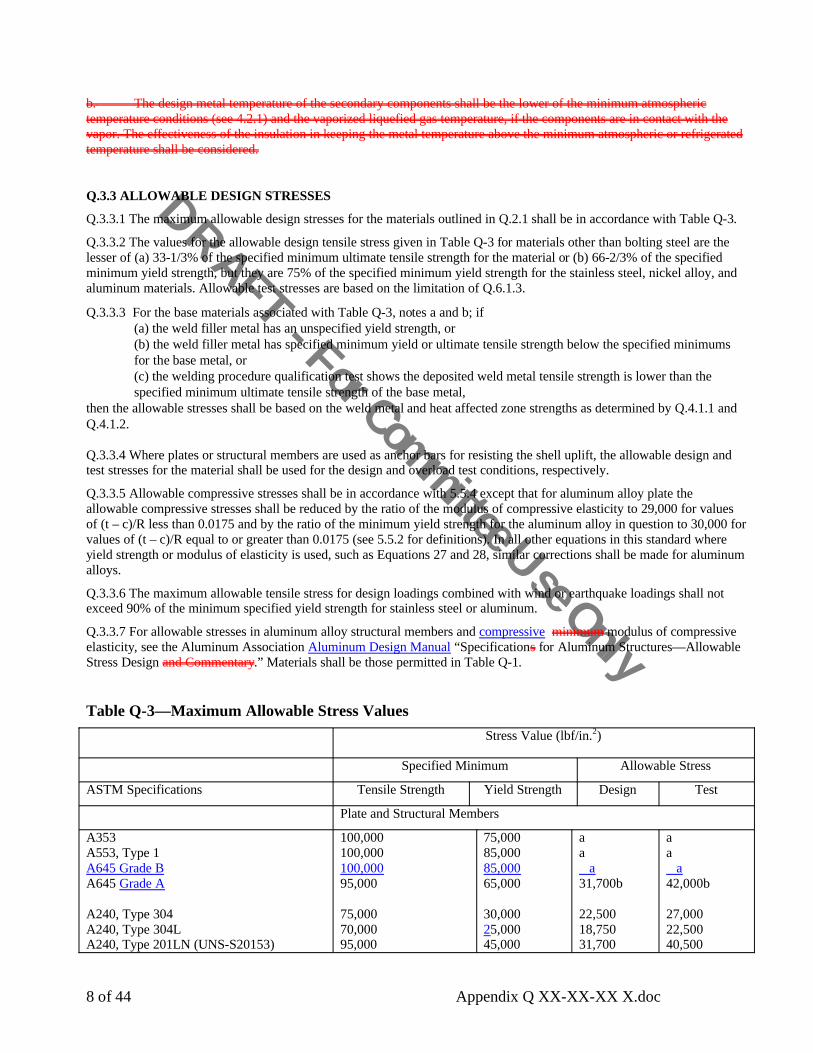
Table Q-3—Maximum Allowable Stress Values Stress Value (lbf/in.2)
Specified Minimum Allowable Stress
ASTM Specifications Tensile Strength Yield Strength Design Test
Plate and Structural Members
A353A553, Type 1A645 Grade BA645 Grade A
A240, Type 304A240, Type 304LA240, Type 201LN (UNS-S20153)
100,000100,000100,00095,000
75,00070,00095,000
75,00085,00085,00065,000
30,00025,00045,000
aa
a31,700b
22,50018,75031,700
aa
a42,000b
27,00022,50040,500

DRAFT - For Committee Use Only
9 of 44 Appendix Q XX-XX-XX X.doc
A240, Type 316A240, Type 316L
B209, Alloy 3003-0B209, Alloy 5052-0
B209, Alloy 5083-0B209, Alloy 5086-0
B209, Alloy 5154-0B209, Alloy 5456-0
B221, Alloy 3003-0B221, Alloy 5052-0
B221, Alloy 5083-0B221, Alloy 5086-0B221, Alloy 5154-0
B221, Alloy 5456-0B221, Alloy 6061-T4 and T6
B308, Alloy 6061-T4 and T6
.75,000 70,000
No changeNo change
No changeNo change
No changeNo change
No changeNo change
No changeNo changeNo change
No changeNo change
No change
.30,00025,000
No changeNo change
No changeNo change
No changeNo change
No changeNo change
No changeNo changeNo change
No changeNo change
No change
.22,50018,750
No changeNo change
No changeNo change
No changeNo change
No changeNo change
No changeNo changeNo change
No changeNo change
No change
.27,00022,500
No changeNo change
No changeNo change
No changeNo change
No changeNo change
No changeNo changeNo change
No changeNo change
No change
Piping and Tubing
A333, Grade 8A334, Grade 8
A213, Grade TP, Type 304A213, Grade TP, Type 304L
A312, Grade TP, Type 304A312, Grade TP, Type 304L
A358, Grade 304, Class 1
A213, Grade TP316A213, Grade TP316LA312, Grade TP316A312, Grade TP316L
B210, Alloy 3303-0
B210, Alloy 3003-H112B210, Alloy 5052-0
B210, Alloy 5086-0B210, Alloy 5254-0
B241, Alloy 5052-0B241, Alloy 5083-0
B241, Alloy 5086-0
No changeNo change
No changeNo change
No changeNo change
No change
75,00070,00075,00070,000
No change
No changeNo change
No changeNo change
No changeNo change
No change
No changeNo change
No changeNo change
No changeNo change
No change
30,00025,00030,00025,000
No change
No changeNo change
No changeNo change
No changeNo change
No change
No changeNo change
No changeNo change
No changeNo change
No change
22,50018,75022,50018,750
No change
No changeNo change
No changeNo change
No changeNo change
No change
No changeNo change
No changeNo change
No changeNo change
No change
27,00022,50027,00022,500
No change
No changeNo change
No changeNo change
No changeNo change
No change

DRAFT - For Committee Use Only
10 of 44 Appendix Q XX-XX-XX X.doc
B241, Alloy 5454-0B241, Alloy 5056-0
B444 (UNS-N06625), Grade 1B444 (UNS-N06625), Grade 2B619 (UNS-N10276), Grade 1c
B622 (N10276)
No changeNo change
No changeNo changeNo changeNo change
No changeNo change
No changeNo changeNo changeNo change
No changeNo change
No changeNo changeNo changeNo change
No changeNo change
No changeNo changeNo changeNo change
Forgings
A552A182, Grade F, Type 304A182, Grade F, Type 304L
A240, Grade F316A240, Grade F316L
B247, Alloy 3003-H112B247, Alloy 5083-H112 Modd
No changeNo changeNo change
75,00070,000
No changeNo change
No changeNo changeNo change
30,00025,000
No changeNo change
No changeNo changeNo change
22,50018,750
No changeNo change
No changeNo changeNo change
27,00022,500
No changeNo change
Bolting
F468 B211, Alloy 6061-T6
Rest of this section is unchanged
No Change No Change No Change No Change
Notes:
a The allowable stresses for these materials are based on the lower yield or tensile strength of the base metal or the weld metal as determined by Q.4.1.1 and Q.4.1.2 and the design rules of Q.3.3.2 and Q.3.3.3. Further, the allowable stresses shall be considered joint by joint as limits on the stress acting across that joint considering the weld metal used at that joint. The minimum measured tensile strength shall be 95,000 lbf/in.2and the minimum measured yield strength shall be 52,500 lbf/in.2 except that for circumferential seams only in the sidewall of a cylindrical tank, the minimum measured tensile strength shall be 80,000 lbf/in.2 and the minimum measured yield strength shall be 42,000 lbf/in.2". For all seams, the maximum permitted values to be used for determining the allowable stress are 100,000 lbf/in.2 for tensile strength and 58,000 lbf/in.2 for yield strength.
b Based on the yield and tensile strength of the weld metal, as determined by Q.4.1. The minimum measured tensile strength shall be 95,000 lbf/in.2 and the minimum measured yield strength shall be 52,500 lbf/in.2.
c For welding piping or tubing, a joint efficiency of 0.80 shall be applied to the allowable stresses for longitudinal joints in accordance with 5.23.3.
d The designation Mod requires that the maximum tensile and yield strength and the minimum elongation of the material conform to the limits of B 209, Alloy 5083-0.
e See 5.6.6.
g These allowable stress values are for materials thickness up to and including 1.5 in. For thickness over 1.5 in., allowable stress values are to be established per Q.3.3.2 using ASTM data of tensile (ultimate) and yield strength for these grades.
f Not to be used for opening reinforcement when used with A 353, A 553, and A 645.
Q.3.4 PIPING
All process piping within the limitations of Q.1.2 (except pump columns as governed by API 625 7.2.3) shall fulfill the minimum design requirements of ASME B31.3, but using the allowable stresses of Table Q-3.

DRAFT - For Committee Use Only
11 of 44 Appendix Q XX-XX-XX X.doc
Q.3.5 4 BOTTOM PLATES FOR PRIMARY AND SECONDARY LIQUID CONTAINERS
Q.3.5.1 The tank shell that contains the liquid Primary liquid containers and secondary liquid containers shall have butt-welded annular bottom plates with a radial width that provides at least 24 in. between the inside of the shell and any lap-welded joint in the remainder of the bottom and at least a 2-in. projection outside the shell. A greater radial width (Lmin) of annular plate is required when calculated by the following equations:
For steel,
Lmin = 390 tb / sqrt[(H)(G)] in.
For aluminum,
Lmin = 255 tb / sqrt[(H)(G)] in.
where
tb = nominal thickness of the annular plate, in in.,
H = design maximum height of the liquid, in ft,
G = design specific gravity of the liquid to be stored.
Q.3.5.2 The thickness of the annular bottom plates shall be in accordance with Table Q-4 (for steel or aluminum, as applicable). The thicknesses shown are minimums.
Table Q-4A—Minimum Thickness for the Annular Bottom Plate: Steel TanksCorrection to first NOTE: “ …..The minimum thickness for annular bottom plates were derived based on a fatigue cyclelife of 1000 cycles for steel aluminum tanks.”
Table Q-4B—Minimum Thickness for the Annular Bottom Plate: Aluminum TanksNO CHANGE
Q.3.5.3 The ring of annular plates shall have a circular outside circumference, but it may have a regular polygonal shape inside the tank shell with the number of sides equal to the number of annular plates. These pieces shall be butt-welded in accordance with Q.5.1.1, Item a b.
Q.3.5.4 The plates of the first shell course shall be attached to the annular bottom plates by a weld as required by 5.9.5 except when a full-penetration weld is used or required (see Q.5.1.1).
Q.3.5.5 Butt-welds in annular plates shall be not closer than 12 in. from any vertical weld.
Q.3.5.6 Three-plate laps or butt-weld junctions in tank bottoms shall be not closer than 12 in. from each other. or from the butt-welds of the annular plates.
Q.3.5.7 Bottom plates, other than annular bottom, plates for a 9% or 5% nickel steel or stainless steel primary or secondary liquid container tank that contains liquid, shall may have a minimum thickness of 3•16 in. exclusive of any specified corrosion allowance.
Q.3.6 SHELL STIFFENING RINGS FOR PRIMARY AND SECONDARY LIQUID CONTAINERS TANKS THAT CONTAIN LIQUID
Fixing typo that
resulted from 620-
293

DRAFT - For Committee Use Only
12 of 44 Appendix Q XX-XX-XX X.doc
Q.3.6.1 Internal or external shell stiffening rings may be required to maintain roundness when the tank is subjected to wind, vacuum, or other specified loads. When stiffening rings are required, the stiffener-to-shell weld details shall be in accordance with Figure Q-1 and Q.3.6.2 through Q.3.6.5.
Q.3.6.2 The stiffener ring and backing strip (if used) are primary components, and they shall comply with the requirements of Q.2.1. The stiffener rings may be fabricated from plate using an intermittent weld on alternating sides between the web and the flange.
Q.3.6.3 One rat hole with a minimum radius of 3•4 in. shall be provided at each longitudinal shell joint and ring juncture weld (see Figure Q-1).
Q.3.6.4 Except for aluminum or stainless steel tanks, all fillet welds shall consist of a minimum of two passes. The ends of the fillet welds shall be 2 in. from the rat hole (see Figure Q-1), and these welds shall be deposited by starting 2 in. from the rat hole and welding away from the rat hole. An acceptable alternative to the detail that includes stopping fillet welds 2 in. short of the rat hole would be to weld continuously through the rat hole from one side of the stiffener to the opposite side. All craters in fillet welds shall be repaired by back welding.
Q.3.6.5 Any joints between the adjacent sections of stiffening rings, as shown in Figure Q-1, shall be made so that the required moment of inertia of the combined ring-shell section is provided. Weld joints between adjacent sections shall be made with full-thickness and full-penetration butt-welds. Stiffening-ring butt-welds may employ metal backing strips. Backing strips and the associated welding shall be made in a manner that provides a smooth contour in the rat hole and all other weld joint ends. All weld passes shall be started at the rat hole and other weld joint ends and shall be completed by moving away from these ends. Passes shall be overlapped away from edges to provide a smooth continuous weld.
Q.3.7 TANK ANCHORAGE FOR PRIMARY AND SECONDARY LIQUID CONTAINERS
Q.3.7.1 In addition to the loads in Q.4, Q.5.1, and Q.5.2, the anchorage for the primary liquid container and any secondary liquid container tank that contains liquid, whether it be a single-wall tank or the inner tank of a double-wall tank, shall be designed to meet the requirements of Q.3.7.2 through Q.3.7.5.
Q.3.7.2 The anchorage shall accommodate movement of the tank wall and bottom caused by thermal changes.
Q.3.7.3 For Appendix Q tanks, 9% or 5% nickel steel, stainless steel, or aluminum anchorage may be used; carbon steel may be used when a corrosion allowance is provided. Aluminum anchorage shall not be imbedded in reinforced concrete unless it is suitably protected against corrosion.
Q.3.7.4 For anchored flat-bottom tanks, the aAnchorage subject to load from internal pressure shall be designed as described in Q.3.7.4.1 through Q.3.7.4.3.
Q.3.7.4.1 When the topshell course is the minimum thickness indicated in Table 5-6, the minimum anchorage shall be designed for normal loads as specified by the purchaser and by this standard. See 5.11.2.3 for the allowable stress.
Q.3.7.4.2 When the topshell course is thickened beyond minimum thickness provided in Table 5-6 or as in Figure 5-6, details f and g, or a knuckle is used, the minimum anchorage shall be designed for three times the internal design pressure. The allowable stress for this loading is 90% of the minimum specified yield strength of anchorage material.
Q.3.7.4.3 As an alternative to Q.3.7.4.2, the purchaser may specify a combination of normal anchorage design, (see Q.3.7.4.1) and emergency venting. The purchaser shall specify required emergency or upset condition venting discharge rates (see 9.2 and K.1).”
Q.3.7.5 The foundation design loading for Q.3.7.4 is described in Q.8.4.4.
Q.3.8 COMBINATION OF DESIGN LOADS FOR DOUBLE-WALL TANKS
The inner and outer containers shall be designed for the most critical load combinations per 5.4.2. and per Q.3.8.1 through Q.3.8.5 as applicable.
Q.3.8.1 Inner Tank
The primary liquid container (inner tank) shall also be designed for the most critical combinations of loading that result from internal pressure and liquid head, for the static insulation pressure, the insulation pressure as the inner tank expands
Q.3.8 was moved from Q.5.2

DRAFT - For Committee Use Only
13 of 44 Appendix Q XX-XX-XX X.doc
during warming after an in-service period, and the purging or operating pressure of the space between the inner and outer tank shells, unless the pressure is equalized on both sides of the inner tank.
Q.3.8.2 Single Containment Outer Wall
The outer wall shall A metallic warm vapor, or purge gas container for a double wall, single containment tank system shall also be designed for the purging and operating pressure of the space between the inner and outer tank shells and for the loading from the insulation. the pressure of wind forces, and the roof loading.
Q.3.8.3 Double Containment Outer Wall
A metallic warm vapor, purge gas, or secondary liquid container for a double containment tank system shall be designed for the load combinations specified for the outer wall of a single containment tank system. A metallic secondary liquid container shall also be designed for the following upset conditions:
a. Dead load and liquid head [ DL + PL ]
b. Dead load, liquid head, and seismic [ DL + P L + E ]
where DL , P L & E are defined in Q.3.8.5
Q.3.8.4 Full Containment Outer Wall
A metallic outer wall for a full containment tank system shall be designed for the load combinations specified for the outer wall of a single containment tank system. The metallic outer wall shall also be designed for the following upset conditions:
a. Dead load, design pressure and liquid head [ DL + Pg + PL ]
b. Dead load, design pressure, liquid head, and seismic [ DL + Pg + P L + E ]
where DL , Pg, P L & E are defined in Q.3.8.5:
Q.3.8.5 Nomenclature
DL = Dead load
Pg = Design pressure of the secondary liquid container
PL = Liquid head in the secondary liquid container determined from the maximum normal operating capacity of the primary liquid container
E = ALE seismic as required by L.4. including 10% snow load
Q.3.9 MINIMUM WALL REQUIREMENTS
Q.3.9.1 Warm Vapor and Purge Gas Containers Outer Wall
The outer bottom, shell, and roof Warm Vapor and Purge Gas Containers shall have a minimum nominal thickness of 3•16 in. (7.65 lbf/ft2) and shall conform to the material requirements of Q.2.3.
<<<<Last statement adds nothing. Q.2.3 covers it>>>
Q.3.9.2 Primary and Secondary Liquid Containers Inner Tank
The sidewall thickness of a metallic primary or secondary liquid container shall in no case shall the nominal thickness of the inner tank cylindrical sidewall plates be less than that described in Table Q-5. the plates shall conform to the material requirements of Q.2.1.
Note: The nominal thickness of cylindrical sidewall plates refers to the tank shell as constructed. The thicknesses specified are based on erection requirements.
Q.3.9.3 Inner Primary and Secondary Liquid Container Tank Tolerances
Q.3.9 was moved from Q.5.3
DRAFT - For Committee Use Only
14 of 44 Appendix Q XX-XX-XX X.doc
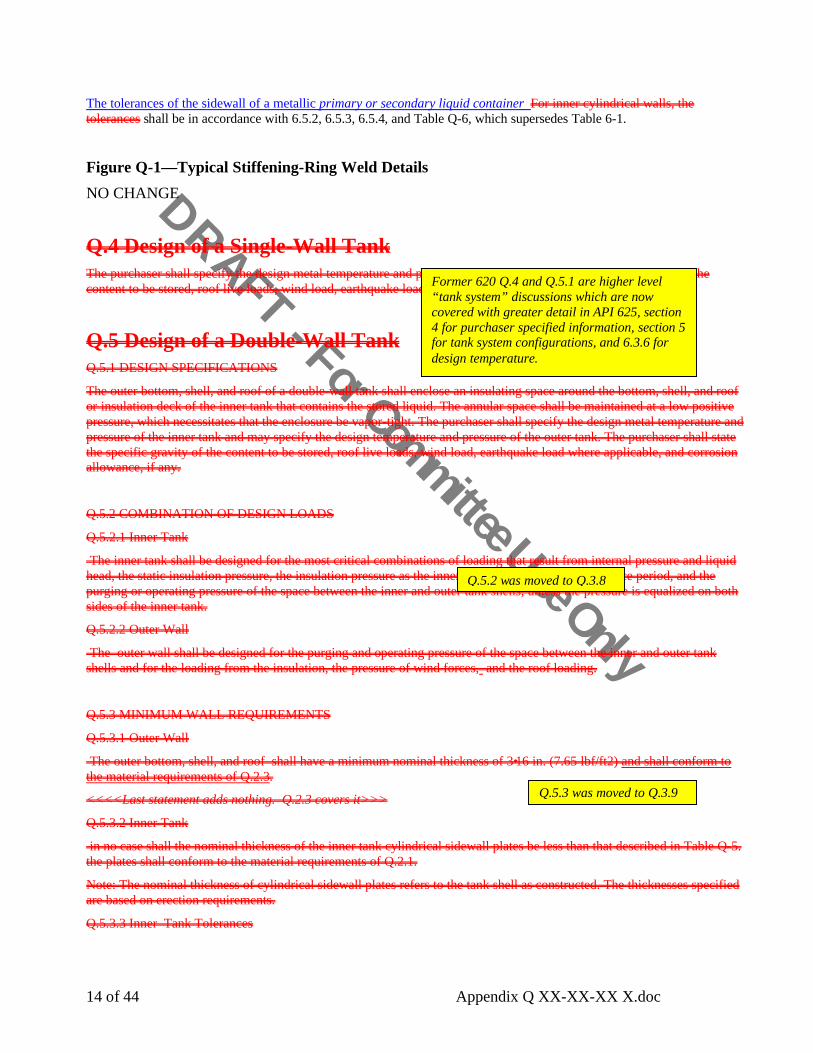
The tolerances of the sidewall of a metallic primary or secondary liquid container For inner cylindrical walls, the tolerances shall be in accordance with 6.5.2, 6.5.3, 6.5.4, and Table Q-6, which supersedes Table 6-1.
Figure Q-1—Typical Stiffening-Ring Weld DetailsNO CHANGE
Q.4 Design of a Single-Wall TankThe purchaser shall specify the design metal temperature and pressures (internal and external), specific gravity of the content to be stored, roof live loads, wind load, earthquake load where applicable, and corrosion allowance, if any.
Q.5 Design of a Double-Wall TankQ.5.1 DESIGN SPECIFICATIONS
The outer bottom, shell, and roof of a double-wall tank shall enclose an insulating space around the bottom, shell, and roof or insulation deck of the inner tank that contains the stored liquid. The annular space shall be maintained at a low positive pressure, which necessitates that the enclosure be vapor-tight. The purchaser shall specify the design metal temperature and pressure of the inner tank and may specify the design temperature and pressure of the outer tank. The purchaser shall state the specific gravity of the content to be stored, roof live loads, wind load, earthquake load where applicable, and corrosion allowance, if any.
Q.5.2 COMBINATION OF DESIGN LOADS
Q.5.2.1 Inner Tank
The inner tank shall be designed for the most critical combinations of loading that result from internal pressure and liquid head, the static insulation pressure, the insulation pressure as the inner tank expands after an in-service period, and the purging or operating pressure of the space between the inner and outer tank shells, unless the pressure is equalized on both sides of the inner tank.
Q.5.2.2 Outer Wall
The outer wall shall be designed for the purging and operating pressure of the space between the inner and outer tank shells and for the loading from the insulation, the pressure of wind forces, and the roof loading.
Q.5.3 MINIMUM WALL REQUIREMENTS
Q.5.3.1 Outer Wall
The outer bottom, shell, and roof shall have a minimum nominal thickness of 3•16 in. (7.65 lbf/ft2) and shall conform to the material requirements of Q.2.3.
<<<<Last statement adds nothing. Q.2.3 covers it>>>
Q.5.3.2 Inner Tank
in no case shall the nominal thickness of the inner tank cylindrical sidewall plates be less than that described in Table Q-5. the plates shall conform to the material requirements of Q.2.1.
Note: The nominal thickness of cylindrical sidewall plates refers to the tank shell as constructed. The thicknesses specified are based on erection requirements.
Q.5.3.3 Inner Tank Tolerances
Former 620 Q.4 and Q.5.1 are higher level “tank system” discussions which are now covered with greater detail in API 625, section4 for purchaser specified information, section 5 for tank system configurations, and 6.3.6 for design temperature.
Q.5.2 was moved to Q.3.8
Q.5.3 was moved to Q.3.9

DRAFT - For Committee Use Only
15 of 44 Appendix Q XX-XX-XX X.doc
For inner cylindrical walls, the tolerances shall be in accordance with 6.4.2.1, 6.4.2.2.2, 6.4.2.3, and Table Q-6, which supersedes Table 6-1.
Table Q-5—Nominal Thickness of Inner Tank Primary and Secondary Liquid ContainerCylindrical Sidewall PlatesCHANGE ONLY TO TITLE, NO CHANGE TO CONTENT
Table Q-6—Radius Tolerances for the Inner Tank Primary and Secondary Liquid ContainerShellsCHANGE ONLY TO TITLE, NO CHANGE TO CONTENT
Q.4 Welding ProceduresThe rules in this section shall apply to primary and secondary liquid containers, refrigerated temperature roofs and suspended insulation decks. all primary components of the tank. Covered electrodes, and bare-wire electrodes, and flux cored electrodes used to weld 9% and 5% nickel steel shall be limited to those listed in AWS 5.11, and AWS 5.14, and AWS 5.34. The secondary components Warm vapor and purge gas containers shall be welded in accordance with the basic rules of this standard unless the requirements of this appendix or Appendix R are applicable.
The outer tank, which is not in contact with the vaporized liquefied gas, Purge gas containers may be of single-welded lap or single-welded partial penetration butt construction when the thickness does not exceed 3•8 in. Such single side welds shall be made from the outside to prevent corrosion and the entrance of moisture. At any thickness, the outer tank may be of single-welded butt construction from either side with full penetration and fusion or double-welded butt construction without necessarily having full fusion and penetration.
When the outer tank is in contact with the vaporized liquefied gas, it Warm vapor containers shall conform to the lap- or butt-welded construction described in this standard except as required in Q.5.1.2.2.
Q.4.1 WELDING PROCEDURE QUALIFICATION
Q.4.1.1 Specifications for the standard welding procedure tests and confirmation of the minimum ultimate tensile strength are found in 6.7.
Q.4.1.2 When required by Q.3.3.3, two all-weld-metal specimens that conform to the dimensional standard of Figure 9 of AWS A5.11 shall be tested to determine the minimum yield and ultimate tensile strength required by Table Q-3; or for determining allowable stress values in Q.3.3.2. The yield strength shall be determined by the 0.2% Offset Method.
Q.4.2 IMPACT TESTS FOR 9% AND 5% NICKEL STEEL
Impact tests for primary components of 9% and 5% nickel steel shall be made for each welding procedure as described in Q.4.2.1 through Q.4.2.5.
Q.4.2.1 Charpy V-notch specimens shall be taken from the weld metal and from the heat-affected zone of the welding procedure qualification test plates or from duplicate test plates.
Q.4.2.2 Weld metal impact specimens shall be taken across the weld with the notch in the weld metal. The specimen shall be oriented so that the notch is normal to the surface of the material. One face of the specimen shall be substantially parallel to and within 1/16 in. of the surface.
Q.4.2.3 Heat-affected zone impact specimens shall be taken across the weld and as near the surface of the material as is practicable. The specimens shall be of sufficient length to locate the notch in the heat-affected zone after etching. The notch
Note: Passed item 620-293 is incorporated in section Q.4of this draft. It was missed by Publishing at March 09.

DRAFT - For Committee Use Only
16 of 44 Appendix Q XX-XX-XX X.doc
shall be cut approximately normal to the material surface to include as much heat-affected zone material as possible in the resulting fracture.
Q.4.2.4 Impact test specimens shall be cooled to the temperature stated in Q.2.2.
Q.4.2.5 The required impact values and lateral expansion values of the weld metal and the heat-affected zone shall be as given in Q.2.2.2, items c and d, respectively. Where erratic impact values are obtained, retests will be allowed if agreed upon by the purchaser and the manufacturer.
Q.4.3 IMPACT TESTS FOR HIGH ALLOYS
Q.4.3.1 Impact tests are not required for the high-alloy (austenitic stainless steel) base materials, nickel alloy based materials, aluminum base materials, and weld deposited for the nonferrous (aluminum) materials.
Q.4.3.2 Impact tests are not required for austenitic stainless steel welds deposited by all the welding processes for services of – 200°F and above.
Q.4.3.3 Austenitic stainless steel welds deposited for service below – 200°F by all welding processes shall be impact tested in accordance with Q.4.2 except that the required impact values shall be 75% of the values as given in Q.2.2.2, item c. Electrodes used in the production welding of the tank shall be tested to meet the above requirements.
Q.4.3.4 Impact tests are not required for nickel alloy welds made with electrodes/filler metals covered by AWS Specification A5.11or AWS Specification A5.14 provided the nominal nickel content is 50% or greater and weld is deposited by the shielded metal-arc welding (SMAW) the gas metal-arc welding (GMAW) , the gas tungsten-arc welding (GTAW) or the plasma-arc welding (PAW) processes. When A5.11/A5.14 specifies the nickel content as a “remainder”, then the nickel content shall be determined by summing the maximum specified values of the other elements (use the average specified value for elements with specified ranges) and subtracting from 100%.
Q.4.4 IMPACT TESTS FOR WARM VAPOR CONTAINER SECONDARY COMPONENTS
When impact tests are required by Q.2.3.1 for warm vapor container secondary components, they shall conform to the requirements of ASTM A 20, Supplementary Requirement, paragraph S 5, this appendix, or Appendix R, whichever is applicable.
Q.4.5 PRODUCTION WELDING PROCEDURES
The production welding procedures and the production welding shall conform to the requirements of the procedure qualification tests within the following limitations:
a. Individual weld layer thickness shall not be substantially greater than that used in the procedure qualification test.
b. Electrodes shall be of the same AWS classification and shall be of the same nominal size or smaller.
c. The nominal preheat and interpass temperatures shall be the same.
Q.4.6 PRODUCTION WELD TESTS
Q.4.6.1 Production weld test plates shall be welded for primary and secondary liquid container primary-component butt-welded shell plates when welding procedure qualifications are required to be impact tested per paragraphs Q.4.2 and Q.4.3. The number of production weld tests shall be based on the requirements of Q.4.6.3 and Q.4.6.4. The locations impact tested (i.e. HAZ and/or weld deposits) shall likewise be the same as required for weld procedure qualifications per paragraphs Q.4.2 and Q.4.3. Weld testing shall be in accordance with Q.4.6.5. Test plates shall be made from plates produced only from the heats that are used to produce the shell plates for the tank.
Q.4.6.2 Test plates shall be welded using the same qualified welding procedure and electrodes that are required for the tank shell plate joints. The test plates need not be welded as an extension of the tank shell joint but shall be welded in the required qualifying positions.
Q.4.6.3 One test weld shall be made on a set of plates from each specification and grade of plate material, using a thickness that would qualify for all thicknesses in the shell. Each test welded of thickness t shall qualify for plate thicknesses from 2t

DRAFT - For Committee Use Only
17 of 44 Appendix Q XX-XX-XX X.doc
down to t/2, but not less than 5/8 in. For plate thicknesses less than 5/8 in., a test weld shall be made for the thinnest shell plate to be welded; this test weld will qualify plate thicknesses from t up to 2t.
Q.4.6.4 Test welds shall be made for each position and for each process used in welding primary and secondary liquid containers’ shell plates tank shell except for the following:a. A manual or semi-automatic vertical test weld will qualify manual or semi-automatic welding using the same weld
process in all positions. b. A semi-automatic vertical test weld will qualify machine welding using the same weld process in all positions.c. Test welds are not required for machine welded circumferential joints in cylindrical shells.
Q.4.6.5 The impact specimens and testing procedure shall conform to Q.4.2.1 through Q.4.2.5 for 9-percent and 5-percent nickel steel. The impact specimens and testing procedure shall conform to Q.4.3.3 for austenitic stainless steel welds deposited for service below –200oF.
Q.4.6.6 By agreement between the purchaser and the manufacturer, production test welds for the first tank shall satisfy the requirements of this paragraph for similar tanks at the same location provided that the tanks are fabricated within six months of the time the impact tests were made and found satisfactory, and the same weld procedure specifications are used
Q.5 Requirements for Fabrication, Openings, Examination and Testingand InspectionQ.5.1 WELDING OF PRIMARY COMPONENTS MISCELLANEOUS REQUIREMENTS FOR PRIMARY AND SECONDARY LIQUID CONTAINERS AND REFRIGERATED TEMPERATURE ROOFS
Q.5.1.1 The following primary components shall be joined with double butt-welds that have complete penetration and complete fusion except as noted:
a. Longitudinal and circumferential shell joints and joints that connect the annular bottom plates together. When approved by purchaser, these may be welded from a single side provided temporary non-fusible backing is used with complete penetration and complete fusion. Both sides of the joint shall be 100% visually examined as specified in 7.15.5.b. Joints that connect sections of compression rings and sections of shell stiffeners together. Backup bars may be used for these joints with complete penetration and complete fusion detail.c. Joints around the periphery of a shell insert plate.d. Joints that connect the shell to the bottom, unless a method of leak checking is used (see Q.6.2.2), inwhich case double fillet welds are acceptable (see Q.6.2.2).e. Joints that connect nozzle necks to flanges.
f. Butt-welds in piping nozzles, manway necks, and pipe fittings, including weld neck flanges, shall be made using double butt-welded joints. When accessibility does not permit the use of double butt-welded joints, single butt-welded joints that ensure full penetration through the root of the joint are permitted.
Q.5.1.2 Fillet welds shall be made in the manner described in Q.5.1.2.1 and Q.5.1.2.2.
Q.5.1.2.1 All primary components joined together by fillet welds shall have a minimum of two passes, except aluminum material and as permitted for stiffening ring attachment to shell (see Q.3.6.4).
Q.5.1.2.2 For 9% nickel material, sandblasting or other adequate means must be used to remove mill scale from all plate edges and surfaces before fillet welds in contact with the refrigerated liquid and vaporized liquefied gas are welded. Sandblasting, or other adequate means, is required to remove slag from the first welding pass if coated electrodes are used.
Q.5.1.3 Slip-on flanges may be used where specifically approved by the purchaser.
“f” & “g” weremoved from existing Q.7.1.3 to make structure same as Appendix R.
Examination vs
Inspection
terminology
fixed constent
with NFPA
59A and with API
agenda item
620-298.

DRAFT - For Committee Use Only
18 of 44 Appendix Q XX-XX-XX X.doc
Q.7.1.3 Butt-welds in piping nozzles, manway necks, and pipe fittings, including weld neck flanges, shall be made using double butt-welded joints. When accessibility does not permit the use of double butt-welded joints, single butt-welded joints that ensure full penetration through the root of the joint are permitted.
Q.5.1.4 Connections in Primary Components
Q.5.1.4.1 All connections located in primary components shall have complete penetration and complete fusion.
Q.5.1.4.2 Acceptable types of welded opening connections are shown in Figure 5-8, panels a, b, c, g, h, m, and o.
Q.5.1.4.3 Flanges for nozzles and manways shall be in accordance with this standard; however, the material shall comply with the requirements of Q.2.1 or Q.2.2.
Q.5.1.4.4 Manways shall have welded closures rather than depending on gaskets.
Q.5.2 Q.5.1.2.2 WARM VAPOR CONTAINER BOTTOM LAP WELDS
Warm vapor container Outer tank bottom components exposed to vaporized liquefied gas and joined together by fillet welds shall have a minimum of two passes.
Q.5.3 POSTWELD HEAT TREATMENT
Q.5.3.1 Cold-formed 9% and 5% nickel plates shall be postweld heat treated (or stress relieved) when the extreme fiber strain from cold forming exceeds 3%. Cold-formed 201LN stainless steel shall be reheat-treated in accordance with ASTM A480 when the extreme fiber strain from cold forming exceeds 4%. Forming strain shall be determined by the formula:
S = (65t/Rf) (1-Rf/Ro)
where
s = strain, in percent,
t = plate thickness, in in.,
Rf = final radius, in in.,
Ro = original radius, in in. (infinity for flat plate).
Q.5.3.2 If postweld heat treatment (or stress relief) is required for 9% and 5% nickel, the procedure shall be in accordance with paragraph UCS-56 in Section VIII of the ASME Code (with a holding temperature range from 1025°F to 1085°F), but the cooling rate from the postweld heat treatment shall be not less than 300°F per hour down to a temperature of 600°F. A vessel assembly, or plate that requires postweld heat treatment, must be postweld heat treated in its entirety at the same time. Methods for local or partial postweld heat treatment cannot be used. Pieces individually cold formed that require postweld heat treatment may be heat treated before being welded into the vessel or assembly.
Q.5.3.3 Postweld heat treatment of nonferrous materials is normally not necessary or desirable. No postweld heat treatment shall be performed except by agreement between the purchaser and the manufacturer.
Q.5.3.4 Postweld heat treatment of austenitic stainless steel materials is neither required nor prohibited, but paragraphs UHA-100 through UHA-109 in Section VIII of the ASME Code shall should be carefully reviewed if in case postweld heat treatment is should be considered by the purchaser or the manufacturer.
Q.5.4 SPACING OF CONNECTIONS AND WELDS
Q.5.4.1 In primary and secondary liquid containers primary components, all opening connections 12 in. or larger in nominal diameter in a shell plate that exceeds 1 in. in thickness shall conform to the spacing requirements for butt and fillet welds described in Q.5.4.2. through Q.5.4.4.
Q.5.4.2 The butt-weld around the periphery of a thickened insert plate, or the fillet weld around the periphery of a reinforcing plate, shall be at least the greater of 10 times the shell thickness or 12 in. from any butt-welded seam or the
Q.5.1.4 was Q.7.2
Q.5.2 was Q.7.1.2.2

DRAFT - For Committee Use Only
19 of 44 Appendix Q XX-XX-XX X.doc
bottom-to-shell or roof-to-shell joint. As an alternative, the insert plate (or the reinforcing plate in an assembly that does not require stress relief) may extend to and intersect a flat-bottom-to-shell corner joint at approximately 90 degrees.
Q.5.4.3 In cylindrical tank walls, the longitudinal weld joints in adjacent shell courses, including compression ring welds, shall be offset from each other a minimum distance of 12 in.
Q.5.4.4 Radial weld joints in a compression ring shall be not closer than 12 in. from any longitudinal weld in an adjacent shell or roof plate.
Q.5.5 INSPECTION EXAMINATION OF WELDS BY THE LIQUID-PENETRANT METHOD
Q.5.5.1 The following primary and secondary liquid container primary-component welds shall be inspected examined by the liquid-penetrant method after stress relieving, if any, and before the hydrostatic test of the tank:
a. All longitudinal and circumferential butt-welds not completely radiographed. Inspection Examination shall be on both sides of the joint.
b. The welded joint that joins the cylindrical wall of the tank to the bottom annular plates.
c. All welds of opening connections that are not completely radiographed, including nozzle and manhole neck welds and neck-to-flange welds. Inspection Examination shall also include the root pass and every 1•2 in. of thickness of deposited weld metal (see 5.27.11) as welding progresses.
d. All welds of attachments to primary components, such as stiffeners, compression rings, clips, and other nonpressure parts.
e. All welded joints on which backing strips are to remain shall also be examined by the liquid-penetrant method after the first complete layer (normally two beads) two layers (or beads) of weld metal have been deposited.
Q.5.5.2 All longitudinal and circumferential butt-welds in thermal distance pieces connecting cold piping to warm vapor or purge gas containers shall also be examined by the liquid-penetrant method
Q.5.6 RADIOGRAPHIC/ULTRASONIC EXAMINATION OF BUTT–WELDS IN PLATESPrimary and secondary liquid container Primary-component butt-welds shall be examined by radiographic methods or by ultrasonic methods. When the term “examination” is used in section Q.5.6 and its subsections, it shall be understood to refer to radiographic or ultrasonic examination. The extent of the examination shall be as listed in Q.5.6.1 through Q.5.6.7. When the examination is by the ultrasonic method, it shall be done in accordance with the requirements of Appendix U.
Q.5.6.1 Butt-welds in all tank wall courses subjected to a maximum actual operating membrane tensile stress perpendicular to the welded joint that is greater than 0.1 times the specified minimum tensile strength of the plate material shall be completely examined.
Q.5.6.2 Butt-welds in all tank wall courses subjected to a maximum actual operating membrane tensile stress perpendicular to the welded joint that is less than or equal to 0.1 times the specified minimum tensile strength of the plate material shall be examined in accordance with Figure Q-2.
Q.5.6.3 Butt-welds around the periphery of a thickened insert plate shall be completely examined. This does not include the weld that joins the insert plate with the bottom plate of a flat-bottom tank.
Q.5.6.4 Butt-welds at all three-plate junctions in the tank wall shall be examined except in the case of a flat bottom (wall) supported uniformly by the foundation. This does not include the shell-to-bottom weld of a flat-bottom tank. See Figure Q-2 for minimum examination dimensions.
Q.5.6.5 Twenty-five percent of the butt-welded annular plate radial joints shall be spot examined for a minimum length of 6 inches. The location shall be under the tank shell at the outer edge of the joint.

DRAFT - For Committee Use Only
20 of 44 Appendix Q XX-XX-XX X.doc
Q.5.6.6 Twenty-five percent of the butt-welded compression bar radial joints shall be spot examined for a minimum length of 6 inches except as required by 5.26.5.3.
Q.5.6.7 For aluminum tanks, radiography shall satisfy API 650, Appendix AL. be judged according to the requirements ofASME B96.1.
Figure Q-2 – Radiographic/Ultrasonic Examination Requirements for Butt-Welded Shell Joints in Primary and Secondary Liquid Containers Cylindrical Flat-Bottom Tanks
Q.5.7 INSPECTION EXAMINATION OF BUTT-WELDS IN PIPING
Q.5.7.1 Butt-welds in piping and in pipe fittings within the limitations of 1.3.2 (including the annular space of double-wall tanks) API 625, section 1.6 shall be inspected examined in conformance with Q.5.7.2 through Q.5.7.9 6.
Q.5.7.2 Longitudinal welded joints in piping carrying that contains liquid shall be completely radiographed except for manufactured pipe welded without filler metal, 12 in. or less in diameter, which is tested hydrostatically or by eddy current to ASTM requirements.
Q.5.7.3 Longitudinal welded joints in piping carrying that contains vapor shall be completely radiographed except for manufactured pipe welded without filler metal, 18 in. or less in diameter, which is tested hydrostatically or by eddy current to ASTM requirements.
Q.5.7.4 Thirty percent of the circumferential welded joints (including weld neck flange to pipe joints) in liquid and vapor carrying all piping shall be 100% radiographed.
Q.5.7.5 Butt-welded joints used to fabricate tank liquid and vapor carrying built-up pipe fittings shall be completely radiographed.
Q.5.7.6 Lines carrying liquid located outside the primary liquid container in double wall tanks shall be hydrostatically or pneumatically pressurized at a minimum pressure of 35 lbf/in.2 and butt welded joints shall be simultaneously visually examined (hydrostatic) or solution film tested (pneumatic) for tightness. If manufactured pipe has been hydrostatically tested previously to ASTM requirements, then only circumferential welds need to be examined.
Q.5.7.7 Lines carrying product vapor within a purge gas container’s annular space shall be pneumatically pressurized at a minimum pressure of 5 lbf/in2 and circumferential butt welded joints shall be simultaneously solution film tested for tightness.
Q.5.7.8 For piping that does not carry liquid or product vapor (e.g. instrument conduit and purge lines) examination needs to satisfy only the applicable requirements of Q.2.
Q.5.7.9 Method of examination and acceptance criteria for radiography of butt welds in piping shall comply with ASME B31.3 Process Piping rules, Normal Fluid Service conditions.
Q.5.8 PERMANENT ATTACHMENTS
All permanent structural attachments welded directly to 9% and 5% nickel steel shall be of the same material or of an austenitic stainless steel type that cannot be hardened by heat treatment.
Q.5.9 NON–PRESSURE PARTS
Welds for pads, lifting lugs, and other nonpressure parts, as well as temporary lugs for alignment and scaffolding attached to primary and secondary liquid containers and refrigerated temperature roofs primary components, shall be made in full compliance with a welding procedure qualified in accordance with Q.4.1. Lugs attached for erection purposes shall be removed, and any significant projections of weld metal shall be ground to a smooth contour. Plate that is gouged or torn in removing the lugs shall be repaired using a qualified procedure and then ground to a smooth contour. Where such repairs are made in primary components, in primary and secondary liquid containers the area shall be inspected examined by the liquid-penetrant method. A visual inspection examination is adequate for repairs in warm vapor and purge gas containerssecondary components.
DRAFT - For Committee Use Only
21 of 44 Appendix Q XX-XX-XX X.doc
Q.5.10 REPAIRS TO WELDED JOINTS
When repairs are made to welded joints, including the welds in Q.5.9, the repair procedure shall be in accordance with a qualified welding procedure.
Q.5.11 MARKING OF MATERIALS
Q.5.11.1 Material for primary and secondary liquid containers, and refrigerated temperature roofs, primary componentsshall be marked so that the individual components can be related back to the mill test report. For aluminum materials, a certificate of conformance shall be provided in place of a mill test report stating that the material has been sampled, tested, and be inspected examined in accordance with the specifications and has met the requirements.
Q.5.11.2 All mill markings shall be in accordance with the requirements of ASTM A20 and ASTM A480 as applicable. All material markings performed by the tank manufacturer shall be in accordance with the requirements of sections 7.7 & Q.5.11.1.
Q.5.11.3 Under some conditions, marking material that contains carbon or heavy-metal compounds can cause corrosion of aluminum. Chalk, wax-base crayons, or marking inks with organic coloring are usually satisfactory.
Q.5.12 CONSTRUCTION PRACTICES
Excessive hammering during fabrication and construction shall should be avoided on primary and secondary liquid containers and refrigerated temperature roofs, primary components so that the material is not hardened or severely dented. Any objectionable local thinning caused by hammering can be repaired by welding using a qualified procedure, followed by grinding. The extent of rework for any repair that is permissible must be agreed to between the purchaser and the manufacturer. If the rework is determined to have been excessive, the reworked area shall should be cut out and replaced.
Q.5.13 PROTECTION OF PLATES DURING SHIPPING AND STORAGE
Plates shall be adequately protected during shipping and storage to avoid damage to plate surfaces and edges from handling (scratches, gouge marks, etc.) and from environmental conditions (corrosion, pitting, etc.)
Q.5.13.1 Plates shall be protected from moisture or stored in inclined position to prevent water from collecting and standing on surface.
Q.5.13.2 Nine percent and five percent nickel plates which are exposed to humid or corrosive atmosphere shall be sand or grit blasted and coated with a suitable coating. The purchaser shall specify when plates are exposed to humid or corrosive atmosphere.
Q.6 Testing the Primary Liquid and Primary Vapor Containers Tank in Contact With the Refrigerated ProductThe provisions stated in Q.6.1 through Q.6.4 this section are testing requirements for the primary liquid container tank refrigerated by the liquid contents. Provisions stated noted in Q.6.5 Q.7 cover the pneumatic testing of the warm vapor container (or when inner tank is not open top, the refrigerated temperature roof). outer tank, which is not in contact with the refrigerated liquid and is subject to a higher temperature that approaches atmospheric.
Q.6.1 GENERAL PROCEDURE
Q.6.1.1 A thorough check for tightness and structural adequacy is essential for the primary liquid container. a single-wall tank or for the inner tank of a double-wall tank. Except as permitted by Q.6.5.8 and Q.6.6, the test shall be conducted after the entire tank is complete but before the insulation is applied. Except as limited by foundation or stress conditions, tThe test shall consist of filling the tank with water to a height equal to the design liquid height times the product design specific gravity times 1.25, but not greater than the design liquid level, and applying an overload air pressure of 1.25 times the pressure for which the vapor space is designed. Where foundation or stress conditions do not permit a test with water to the design liquid level, the height of water shall be limited as stated in Q.6.1.2 and Q.6.1.3.
This change
simplifies the std. In
most cases test height
will end up the same as before. But
a SS LNG tank will
have slightly
thicker ring 1 and a tank on strong
foundation will need
less water.

DRAFT - For Committee Use Only
22 of 44 Appendix Q XX-XX-XX X.doc
Q.6.1.2 The load on the supporting foundation shall preferably not exceed the established allowable bearing value for the tank site. Where a thorough evaluation of the foundation justifies a temporary increase, the established allowable bearing may be increased for the test condition, but the increase shall be not more than 25%.
Q.6.1.2 3 The maximum fill shall not produce a stress in any part of the tank greater than 85% (may be 90% for stainless steel and aluminum materials) of the specified minimum yield strength of the material or 55% of the specified minimum tensile strength of the material.
Q.6.2 TEST PRELIMINARIES
Before the tank is filled with water, the procedures described in Q.6.2.1 through Q.6.2.5 shall be completed.
Q.6.2.1 All welded joints in the bottom and complete penetration and complete fusion sidewall-to-bottom welds shall be inspected examined by applying a solution film to the welds and pulling a partial vacuum of at least 3 lbf/in.2 gauge above the welds by means of a vacuum box with a transparent top.
Q.6.2.2 When the sidewall-to-bottom weld in Q.6.2.1 does not have complete penetration and complete fusion, the initial weld passes, inside and outside of the shell, shall have all slag and nonmetals removed from the surface of the welds andthe welds examined visually. After completion of the inside and outside fillet or partial penetration welds, the welds shall be tested by pressurizing the volume between the inside and outside welds with air pressure to 15 lbf/in.2 gauge and applying a solution film to both welds. To assure that the air pressure reaches all parts of the welds, a sealed blockage in the annular passage between the inside and outside welds must be provided by welding at one or more points. Additionally, a small pipe coupling on the outside weld and communicating with the volume between the welds must be welded on each side of and adjacent to the blockages. The air supply must be connected at one end and a pressure gauge connected to a coupling on the other end of the segment under test.
Q.6.2.3 The attachment welding around all openings and their reinforcements in the bottom, shell, and roof shall be examined by magnetic particle method and solution film test in accordance with 7.18.2.2 and 7.18.2.3
Q.6.2.4 For 9% nickel tanks, all testing surfaces of bottom lap-welds and shell-to-bottom welds shall be cleaned by sandblasting or other adequate means before the vacuum box test to prevent slag or dirt from masking leaks.
Q.6.2.5 Where the pneumatic pressure to be applied in Q.6.4 will be equalized on both sides of the inner tank, all welded joints above the test water level shall be checked with a solution film and by a vacuum box inspection examination.
Q.6.2.6 The attachment fillet welds around bottom openings, which do not permit the application of air pressure behind their reinforcing plates, shall be inspected examined by applying a solution film and by a vacuum box inspectionexamination.
Q.6.3 QUALITY OF TEST WATER
Q.6.3.1 The materials used in the construction of Appendix Q tanks may be subject to severe pitting, cracking, or rusting if they are exposed to contaminated test water for extended periods of time. The purchaser shall specify a minimum quality of test water that conforms to Q.6.3.2 through Q.6.3.8. After the water test is completed, the tank shall be promptly drained, cleaned, and dried.
Q.6.3.2 Water shall be substantially clean and clear.
Q.6.3.3 Water shall have no objectionable odor (that is, no hydrogen sulfide).
Q.6.3.4 Water pH shall be between 6 and 8.3.
Q.6.3.5 Water temperature shall be below 120°F.
Q.6.3.6 For austenitic stainless steel tanks, the chloride content of the water shall be below 50 parts per million.
Q.6.3.7 For aluminum tanks, the mercury content of the water shall be less than 0.005 parts per million, and the copper content shall be less than 0.02 parts per million.
Q.6.3.8 If the water quality outlined in Q.6.3.1 through Q.6.3.7 cannot be achieved, alternative test methods that utilize suitable inhibitors (for example, Na2CO3 and/or NaO3) may be used if agreed to by the purchaser and the manufacturer.
Q.6.4 HYDROSTATIC TEST
Addition of Q.6.2.3
provides consistency
with App R.
DRAFT - For Committee Use Only
23 of 44 Appendix Q XX-XX-XX X.doc
Q.6.4.1 The tank shall be vented to the atmosphere when it is filled with or emptied of water.
Q.6.4.2 During water filling, the elevations of at least eight four equidistant points at the bottom of the tank shell and on top of the ringwall or slab shall be checked. Differential settlement, or uniform settlement of substantial magnitude, requires an immediate stop to water filling. Any further filling with water will depend on an evaluation of the measured settlement.
Q.6.4.3 The tank shall be filled with water to the design liquid level unless height is limited as noted level given in Q.6.1.
Q.6.4.4 After the tank is filled with water and before the pneumatic pressure is applied, anchorage, if provided, shall be tightened against the hold-down brackets.
Q.6.4.5 All welds in the shell, including the corner weld between the shell and the bottom, shall be visually checked for tightness.
Q.6.5 PNEUMATIC PRESSURE
Q.6.5.1 An air pressure equal to 1.25 times the pressure for which the vapor space is designed shall be applied to the enclosed space above the water level. In the case of a double-wall tank with an open-top inner tank, where the air pressure acts against the outer tank and the inner tank is thus not stressed by the air pressure, the inner tank may be emptied of water before the pneumatic pressure test begins.
Q.6.5.2 The test pressure shall be held for 1 hour.
Q.6.5.3 The air pressure shall be reduced until the design pressure is reached.
Q.6.5.4 Above the water level, all welded joints shall be checked with a solution film. A prior vacuum box check may be substituted for the solution-film inspection examination. The solution-film inspection examination shall still be made, above the water level, on all welds around openings, all piping joints, and the compression ring welds to the roof and shell except any listed below:
• Continuous double lap roof to compression ring welds • Shell to compression ring welds, continuous inside and outside, and applying a thickened upper shell ring detail
similar to figure 5-6 details f or f-1 The thickened upper shell ring shall be greater than ½ of the conical compression ring thickness and greater than two times the adjacent shell ring thickness.
• Full fusion butt welded connections
Q.6.5.5 The opening pressure or vacuum of the pressure relief and vacuum relief valves shall be checked by pumping air above the water level and releasing the pressure and then partially withdrawing water from the tank.
Q.6.5.6 After the tank has been emptied of water and is at atmospheric pressure, the anchorage, if provided, shall be rechecked for tightness against the hold-down brackets.
Q.6.5.7 Air pressure, equal to the design pressure, shall be applied to the empty tank, and the anchorage, if provided, and the foundation shall be checked for uplift.
Q.6.5.8 Following the hydrostatic and pneumatic test, all welded seams in the primary liquid container bottom, and complete penetration and complete fusion sidewall-to-bottom welds in the primary liquid container, shall be inspectedexamined by means of a vacuum box test as described in Q.6.2.1. Sidewall-to-bottom welds not having complete penetration and complete fusion shall be inspected examined by means of either a vacuum box test of the inside weld as described in Q.6.2.1, or where approved by the purchaser a direct pressure solution film test as described in Q.6.2.2. If any leaks are detected, they shall be repaired and the vacuum box test repeated. The primary tank hydrostatic test need not be repeated.
Q.6.6 TEMPORARY OPENINGS AFTER HYDROSTATIC TESTWhen approved by the purchaser in writing, and only in the case of tanks which when complete have no shell penetrations, it is permitted to restore by welding up to four temporary shell openings after the hydrostatic test in accordance with the provisions of this section.
Q.6.6.1 Each temporary opening shall be restored by the insertion of a shell plate which matches the thickness and specification of adjacent shell material and is welded into place with full fusion butt welds. The insert plate shall be round with diameter no less than 24” and no greater than 42”.
Q.6.4.3change is
consistant with
change to Q.6.1
above.
Passed to publication
item 620-295 is
incorporated
Last sentence of
Q.6.5.8clarifiesbottomrepairs
fromvacuum
box after h-test. NFPA
asked for more
clarity on this. It fits
with Q.6.1.1.

DRAFT - For Committee Use Only
24 of 44 Appendix Q XX-XX-XX X.doc
Q.6.6.2 The insert plate weld shall not cross any shell seams and shall be at least the greater of 10 times the shell thickness or 12 in. from any other weld in the shell including shell seams, shell-to-bottom weld or attachment welds.
Q.6.6.3 The butt weld around the periphery of the plate shall be examined over 100% of its length by both liquid penetrant method and radiographic method. The liquid penetrant examination is required on the root pass, on the backgouged surface, and on the inside and outside finished weld surfaces. Additionally, the weld shall be vacuum box leak tested.
Q.7 Testing a Purge Gas Container the Outer Tank of a Double-Wall Refrigerated TankQ.7.1 GENERAL
The tightness test shall be made before insulation is installed. Where the pneumatic pressure described in Q.6.5 acts against the warm vapor container outer tank, the testing requirements of Q.6.5 will result in a check of the outer tank, and the procedure outlined in Q.7.2.1 through Q.7.2.5 may be omitted.
Q.7.2 TEST PROCEDURE
Q.7.2.1 The inner tank shall be opened to the atmosphere, and a sufficient amount of water shall be added to the inner tank to balance the upward pressure against the inner tank bottom produced by the pneumatic test of the outer tank; as an alternative, the pressure between the inner and outer tanks can be equalized.
Q.7.2.2 Air pressure shall be applied to the space enclosed by the outer tank equal to at least the design gas pressure but not exceeding a pressure that would overstress either the inner or outer tank.
Q.7.2.3 While the test pressure is being held, all lap welded seams and all welds in connections in the outer shell and roof shall be thoroughly inspected examined with a solution film unless they were previously checked with a vacuum box.
Q.7.2.4 The air pressure shall be released.
Q.7.2.5 Pressure relief and vacuum relief valves shall be checked by applying the design gas pressure to the outer tank, followed by evacuation of the outer space to the vacuum setting of the relief valve.
Q.8 FoundationsQ.8.1 Foundations shall be in accordance with API 625, Section 6.6.
Q.8.1 GENERAL
Appendix C describes the factors involved in obtaining adequate foundations for tanks that operate at atmospheric temperature. The foundations for refrigerated tanks are complicated because of the thermal movement of the tank, the insulation required for the bottom, the effects of foundation freezing and possible frost heaving, and the anchorage required to resist uplift.
The services of a qualified foundation engineer are essential. Experience with tanks in the area may provide sufficient data, but normally a thorough investigation, including soil tests, would be required for proper design of the foundation.
Q.8.2 BEARING ON FOUNDATIONS
Foundations shall preferably be designed to resist the load exerted by the tank and its contents when the tank is filled with water to the design liquid level. Foundations shall be designed at least for the maximum operating conditions including the wind load. During the water test, the total load on the foundation shall not exceed 125% of the allowable loading. If necessary, the water level during the test may be reduced below the design liquid level line so as not to exceed the 25% maximum overload (see Q.6.1.2).
Q.8.3 UPLIFTING FORCE AND DOWNWARD WEIGHTS
The uplifting force to be considered in designing the ringwall or concrete pad foundation may be offset by the coexistent downward weights and forces, including the metal and insulation weight of the shell and roof and the concrete and earth weight transmitted by the anchorage to the shell. The tank shall be assumed to be empty of liquid.
DRAFT - For Committee Use Only
25 of 44 Appendix Q XX-XX-XX X.doc
Q.8.2 UPLIFT ON FOUNDATION
Q.8.2.1 The increased uplift described in Q.8.2.2 Q.8.4.2 and Q.8.2.3 Q.8.4.3 is intended to apply to the size of the ringwall and foundation but not the anchorage.
Q.8.2.2 For tanks with an internal design pressure less than 1 lbf/in.2 gauge, the uplift shall be taken as the smaller of the maximum uplift values computed under the following conditions:
a. The internal design pressure times 1.5 plus the design wind load on the shell and roof.
b. The internal design pressure plus 0.25 psi gauge plus the design wind load on the shell and roof.
Q.8.2.3 For tanks with an internal design pressure of 1 lbf/in.2 gauge and over, the uplift, if any, shall be calculated under the combined conditions of 1.25 times the internal design condition plus the design wind load on the shell and roof.
Q.8.2.4 When the anchorage is designed to meet the requirements of Q.3.7.4.2 Q.3.6.4.2, the foundation should be designed to resist the uplift that results from three times the design pressure with the tank full to the design liquid level. When designing to any of the conditions in this paragraph, it is permissible to utilize friction between the soil and the vertical face of the ringwall and all of the effective liquid weight.
Q.9 MarkingExcept for 8.2 on Division of Responsibility, marking requirements of Section 8 are superseded by the requirements of API 625, section 11
Q.9.1 DATA ON NAMEPLATE
The data required to be marked on the tank by the manufacturer is listed in 8.1 and shall indicate that the tank has been constructed in accordance with Appendix Q.
Q.9.2 LOCATION OF NAMEPLATE
In addition to the requirements of 8.1, the nameplate shall be attached to the tank at an accessible location if it is outside of any insulation or protective covering of the tank. The nameplate for the inner tank shall be located on the outer tank wall but shall refer to the inner tank. The nameplate, if any, for the outer tank of a double-wall tank shall be located adjacent to the nameplate or the inner tank and shall refer to the outer tank.
Q.10 Reference StandardsFor rules and requirements not covered in this appendix or in the basic rules of this standard, the following documents shall
should be referred to for the type of material used in the tank:
a. API 625
b. For 9% and 5% nickel steels, Part UHT in Section VIII of the ASME Code.
c. For stainless steel, Part UHA in Section VIII of the ASME Code.
d. For aluminum, Part UNF in Section VIII of the ASME Code and ASME B96.1 API 650 Appendix AL.
Text on Uplift
restored since it did not fit into API 625 as
once thought it
would.

DRAFT - For Committee Use Only
26 of 44 Appendix Q XX-XX-XX X.doc
APPENDIX RLOW–PRESSURE STORAGE TANKS FOR REFRIGERATED PRODUCTS
LOW–PRESSURE STORAGE TANKS OPERATING BETWEEN +40°F AND -60°F
R.1 ScopeR.1.1 GENERALThe provisions in this appendix form a guide for the materials, design, and fabrication of tanks to be used for the storage of
refrigerated products.
This appendix together with the basic sections of API 620 provides requirements for the materials, design, and fabrication of the metallic portions of a refrigerated tank system. The requirements for a basic API Std 620 tank apply to primary and secondary liquid containers, refrigerated temperature roofs, warm vapor containers, purge gas containers and their appurtenances except where they are superseded by any requirements of this appendix. Requirements for the complete tank system, of which the metallic components are a part, are found in API 625. All other requirements for an API Std 620 tank shall apply.
A refrigerated tank may be a single-wall insulated tank or a double-wall tank that consists of an inner tank for storing the refrigerated liquid and an outer tank that encloses an insulation space (which usually has a lower gas pressure) around the inner tank. A double-wall tank is a composite tank, and the outer tank is not required to contain the product of the inner tank. In a double-wall tank, differences in materials, design, and testing exist between the inner and outer tanks.
R.1.2 PIPING LIMITATIONS
R.1.2 Piping limitations given in API 620 1.3.2 are superseded by API 625, Section 1.6.
R.1.3 PRESSURE RANGEThe provisions in this appendix apply to all design pressures from -0.25 psig to +7.00 psig. within the scope of this standard.
R.1.4 TEMPERATURE RANGEThe provisions in this appendix apply to are considered suitable for design metal temperatures from + 40°F to – 60°F, inclusive.
R.1.5 DEFINITIONSThe definitions of the following specialized terms used in this appendix are found in API 625:R.1.5.1 Refrigerated Tank SystemR.1.5.2 Single Containment Tank SystemR.1.5.3 Double Containment Tank SystemR.1.5.4 Full Containment Tank SystemR.1.5.5 Primary Liquid ContainerR.1.5.6 Secondary Liquid ContainerR.1.5.7 Warm vapor container R.1.5.8 Purge gas containerR.1.5.9 Refrigerated temperature roofR.1.5.10 Design PressureR.1.5.11 Annular Space

DRAFT - For Committee Use Only
27 of 44 Appendix Q XX-XX-XX X.doc
R.1.5.12 Suspended deckR.1.5.13 Design Metal Temperature
R.1.4 PRIMARY COMPONENTS
R.1.4.1 In general, primary components include those components whose failure would result in leakage of the liquid being stored, those exposed to the refrigerated temperature, and those subject to thermal shock. Further definitions of such components are provided in R.1.4.2 and R.1.4.3.
R.1.4.2 The primary components shall include, but will not be limited to, the following parts of a single-wall tank or of the inner tank in a double-wall tank: shell plates; bottom plates; knuckle plates; compression rings; and shell manways and nozzles including reinforcement, shell anchors, piping, tubing, forgings, and bolting. Roof nozzles in contact with the refrigerated liquid shall be considered primary components.
R.1.4.3 The primary components shall also include those parts of a single-wall or an inner tank that are not in contact with the refrigerated liquid but are subject to the refrigerated temperature. Such components include roof plates, roof manways and nozzles with their reinforcements, roof-supporting structural members, and shell stiffeners when the combined tensile and primary bending stresses in these components under design conditions are greater than 6000 lbf/in.2.
R.1.5 SECONDARY COMPONENTS
Secondary components are those whose failure would not result in leakage of the liquid being stored. Secondary components also include those components that are not in contact with the refrigerated liquid but are subject to the refrigerated temperature vapors and have a combined tensile and primary bending stress under design conditions that does not exceed 6000 lbf/in.2. Secondary components that could be designed within this reduced stress are roof plates, including roof manways and nozzles with their reinforcement, roof-supporting structural members, and shell stiffeners.
R.1.6 BASIC COMPONENTS
Basic components are those that contain the vaporized liquefied gas from the stored refrigerated liquid but primarily operate at atmospheric temperatures because of insulation system design and natural ambient heating. These components shall comply with the basic rules of this standard. Examples of such components are the outer wall and roofs of double-wall tanks and roof components above an internally insulated suspended deck.
R.2 MaterialsThe materials requirements are based on the storage of refrigerated products at the design metal temperature.
R.2.1 PRIMARY COMPONENTS PRODUCT TEMPERATURE MATERIALS
R.2.1.1 GeneralMaterials for primary the following metallic components (including their penetrations, piping, anchors, stiffeners and attachments) shall be selected from Table R-1 and shall be impact tested in accordance with R.2.1.2 through R.2.1.4.comply with the requirements of Tables R-1 and R-2. All primary components shall be impact tested in accordance with R.2.1.2 through R.2.1.4.
a) Primary Liquid Containers
b) Secondary Liquid Containers
c) Refrigerated Temperature Roofs (see R.2.2.3 for low stress exception)
(This includes inner roofs of double roof tanks, and single roofs of tanks with external roof insulation)
d) Thermal distance pieces connecting cold piping to warm vapor or purge gas containers.
e) For full containment tank systems; Portions of warm vapor containers that may experience cold gas flows in the event of primary liquid container leakage.
Table R-1—Material for Primary Components Standards for Product Temperature Materials
Component Materials Notes
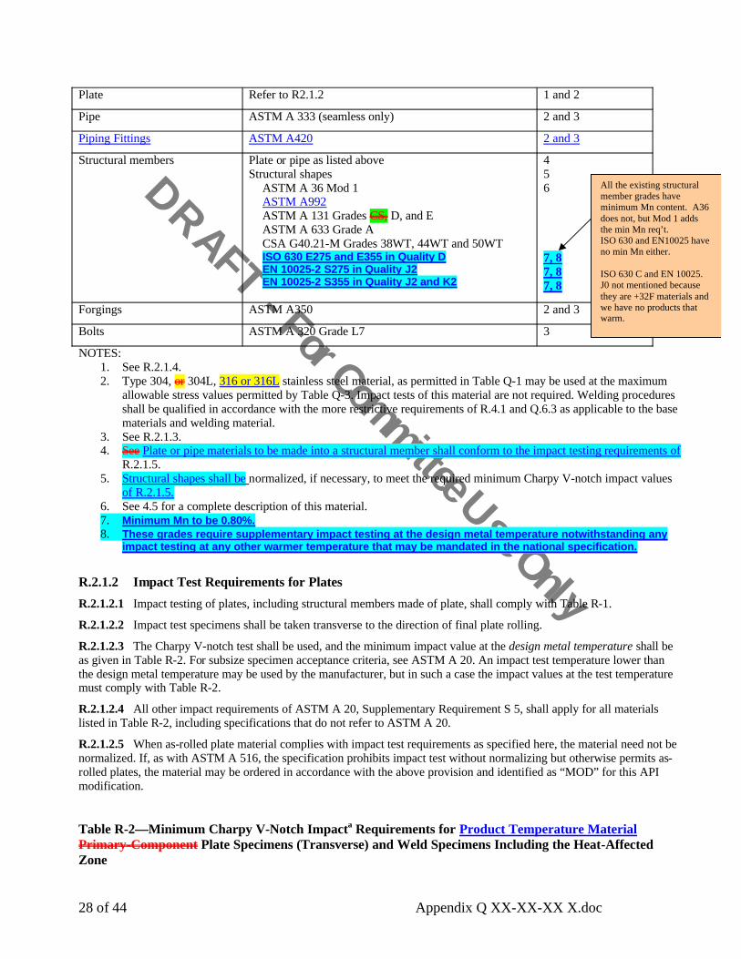
DRAFT - For Committee Use Only
28 of 44 Appendix Q XX-XX-XX X.doc
Plate Refer to R2.1.2 1 and 2
Pipe ASTM A 333 (seamless only) 2 and 3
Piping Fittings ASTM A420 2 and 3
Structural members Plate or pipe as listed above Structural shapes
ASTM A 36 Mod 1ASTM A992ASTM A 131 Grades CS, D, and EASTM A 633 Grade ACSA G40.21-M Grades 38WT, 44WT and 50WTISO 630 E275 and E355 in Quality DEN 10025-2 S275 in Quality J2 EN 10025-2 S355 in Quality J2 and K2
456
7, 87, 87, 8
Forgings ASTM A350 2 and 3
Bolts ASTM A 320 Grade L7 3
NOTES:1. See R.2.1.4.2. Type 304, or 304L, 316 or 316L stainless steel material, as permitted in Table Q-1 may be used at the maximum
allowable stress values permitted by Table Q-3. Impact tests of this material are not required. Welding procedures shall be qualified in accordance with the more restrictive requirements of R.4.1 and Q.6.3 as applicable to the base materials and welding material.
3. See R.2.1.3.4. See Plate or pipe materials to be made into a structural member shall conform to the impact testing requirements of
R.2.1.5. 5. Structural shapes shall be normalized, if necessary, to meet the required minimum Charpy V-notch impact values
of R.2.1.5.6. See 4.5 for a complete description of this material.7. Minimum Mn to be 0.80%.8. These grades require supplementary impact testing at the design metal temperature notwithstanding any
impact testing at any other warmer temperature that may be mandated in the national specification.
R.2.1.2 Impact Test Requirements for PlatesR.2.1.2.1 Impact testing of plates, including structural members made of plate, shall comply with Table R-1.
R.2.1.2.2 Impact test specimens shall be taken transverse to the direction of final plate rolling.
R.2.1.2.3 The Charpy V-notch test shall be used, and the minimum impact value at the design metal temperature shall be as given in Table R-2. For subsize specimen acceptance criteria, see ASTM A 20. An impact test temperature lower than the design metal temperature may be used by the manufacturer, but in such a case the impact values at the test temperature must comply with Table R-2.
R.2.1.2.4 All other impact requirements of ASTM A 20, Supplementary Requirement S 5, shall apply for all materials listed in Table R-2, including specifications that do not refer to ASTM A 20.
R.2.1.2.5 When as-rolled plate material complies with impact test requirements as specified here, the material need not be normalized. If, as with ASTM A 516, the specification prohibits impact test without normalizing but otherwise permits as-rolled plates, the material may be ordered in accordance with the above provision and identified as “MOD” for this API modification.
Table R-2—Minimum Charpy V-Notch Impacta Requirements for Product Temperature MaterialPrimary-Component Plate Specimens (Transverse) and Weld Specimens Including the Heat-Affected Zone
All the existing structural member grades have minimum Mn content. A36 does not, but Mod 1 adds the min Mn req’t.ISO 630 and EN10025 have no min Mn either.
ISO 630 C and EN 10025. J0 not mentioned because they are +32F materials and we have no products that warm.

DRAFT - For Committee Use Only
29 of 44 Appendix Q XX-XX-XX X.doc
SpecificationNumber
Grade Range in Thickness
(in.)
Plate Impact Valueb (ft–lb) Weld Impact Value (ft-lb)
Average Individual Average IndividualASTM A 131ASTM A 516ASTM A 516ASTM A 516ASTM A 516ASTM A 841ASTM A 537ASTM A 537ASTM A 662ASTM A 678ASTM A 678ASTM A 737ASTM A 841
CS c55 and 6065 and 70
65 and 70 Mod 1 d65 and 70 Mod 2 d
112
B and CAc
Bc
B1
3/16 – 11/23/16 – 23/16 – 23/16 – 23/16 – 23/16 – 23/16 – 23/16 – 23/16 – 2
3/16 – 11/23/16 – 23/16 – 23/16 – 2
25252525252525302525302525
20202020202020252020252020
20202020202020252020252020
15151515151515201515201515
ISO 630EN 10028-3
EN 10028-3
CSA G40.21-MCSA G40.21-MCSA G40.21-M
E 355 Quality D c,d,e
P275 Qualities NH, NL1, and NL2P355 Qualities N, NH, NL1, and NL2
260WT c,d,e
300WT c,d,e
350WT c,d,e
3/16 – 23/16 – 2
3/16 – 2
3/16 – 23/16 – 23/16 – 2
2525
25
252525
2020
20
202020
2020
20
202020
1515
15
151515
Notes:a. See R.2.1.2.b. For design metal temperatures of – 40°F and lower, the plate impact values shall be raised 5 ft-lb.c. The frequencies of testing for mechanical and chemical properties shall be at least equal to those of ASTM A 20.d. See 4.2.3 for a complete description of this material.e. The steel shall be fully killed and made with fine-grain practice.
R.2.1.3 Impact Requirements for Pipe, Bolting, and ForgingsThe impact tests for pipe (including structural members made of pipe), bolting, and forgings, shall be in accordance with ASTM specifications referred to in Table R-1.
Piping materials made according to ASTM A 333, A420 and A 350 may be used at design metal temperatures no lower than the impact test temperature required by the ASTM specification for the applicable material grade without additional impact tests. For temperatures below those allowed by the ASTM specification, the following paragraph shall apply.
For all other materials, the impact test temperature shall be at least 30°F colder than the design metal temperature. Alternately, materials impact tested at the design metal temperature or lower with Charpy impact test energy value of 25 ft-lbs (average), 20 ft-lbs (minimum) are acceptable for design metal temperatures above – 40°F. Materials with an energy value of 30 ft-lbs (average), 25 ft-lbs (minimum) are acceptable for design metal temperatures of – 40°F or lower.
R.2.1.4 Impact Requirements for Controlled-Rolled or Thermo-Mechanical Control Process (TMCP) Plates
Subject to the approval of the purchaser, controlled-rolled or TMCP plates (material produced by a mechanical-thermal rolling process designed to enhance the notch toughness) may be used where normalized plates are required. Each plate-as-rolled plate, as rolled, shall be Charpy V-notch tested to the requirements of R.2.1.2.
R.2.1.5 Impact Requirements for Structural ShapesImpact test for structural shapes listed in Table R-1 shall be made in accordance with ASTM A 673 on a piece-testing frequency. Impact values, in foot-pounds, shall be 25 minimum average of 3 and 20 minimum individual at a temperature no warmer than the design metal temperature.
R.2.2 BASIC AND SECONDARY COMPONENTS ATMOSPHERIC TEMPERATURE MATERIALS
Materials for basic and secondary components shall comply with R.2.2.1 and R.2.2.2.
In the E355D spec, FK and FGP is automatic
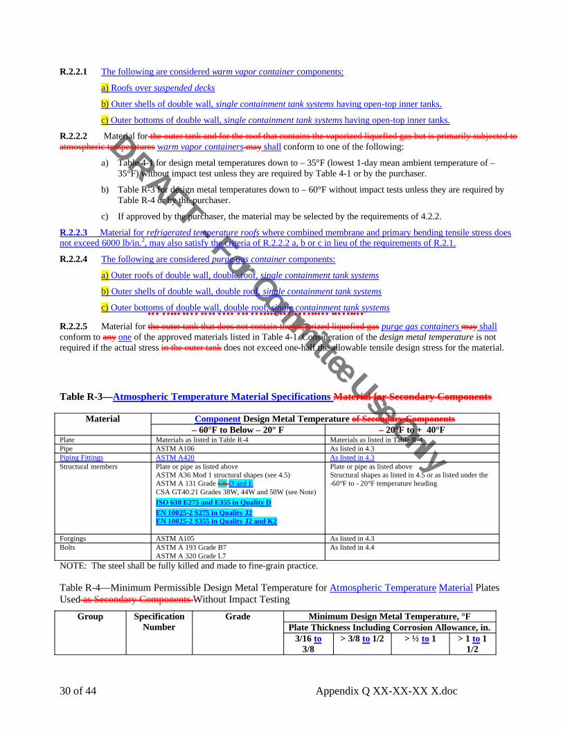
DRAFT - For Committee Use Only
30 of 44 Appendix Q XX-XX-XX X.doc
R.2.2.1 The following are considered warm vapor container components:
a) Roofs over suspended decks
b) Outer shells of double wall, single containment tank systems having open-top inner tanks.
c) Outer bottoms of double wall, single containment tank systems having open-top inner tanks.
R.2.2.2 Material for the outer tank and for the roof that contains the vaporized liquefied gas but is primarily subjected to atmospheric temperatures warm vapor containers may shall conform to one of the following:
a) Table 4-1 for design metal temperatures down to – 35°F (lowest 1-day mean ambient temperature of –35°F) without impact test unless they are required by Table 4-1 or by the purchaser.
b) Table R-3 for design metal temperatures down to – 60°F without impact tests unless they are required by Table R-4 or by the purchaser.
c) If approved by the purchaser, the material may be selected by the requirements of 4.2.2.
R.2.2.3 Material for refrigerated temperature roofs where combined membrane and primary bending tensile stress does not exceed 6000 lb/in.2, may also satisfy the criteria of R.2.2.2 a, b or c in lieu of the requirements of R.2.1.
R.2.2.4 The following are considered purge gas container components:
a) Outer roofs of double wall, double roof, single containment tank systems
b) Outer shells of double wall, double roof, single containment tank systems
c) Outer bottoms of double wall, double roof, single containment tank systems
R.2.2.5 Material for the outer tank that does not contain the vaporized liquefied•••••••••••••••••••••••••••••••••••••••••••••••••••
gas purge gas containers may shallconform to any one of the approved materials listed in Table 4-1. Consideration of the design metal temperature is not required if the actual stress in the outer tank does not exceed one-half the allowable tensile design stress for the material.
Table R-3—Atmospheric Temperature Material Specifications Material for Secondary Components
Component Design Metal Temperature of Secondary ComponentsMaterial– 60°F to Below – 20° F – 20°F to + 40°F
Plate Materials as listed in Table R-4 Materials as listed in Table R-4Pipe ASTM A106 As listed in 4.3Piping Fittings ASTM A420 As listed in 4.3Structural members Plate or pipe as listed above
ASTM A36 Mod 1 structural shapes (see 4.5)ASTM A 131 Grade CS D and ECSA GT40.21 Grades 38W, 44W and 50W (see Note)ISO 630 E275 and E355 in Quality DEN 10025-2 S275 in Quality J2EN 10025-2 S355 in Quality J2 and K2
Plate or pipe as listed aboveStructural shapes as listed in 4.5 or as listed under the -60°F to - 20°F temperature heading
Forgings ASTM A105 As listed in 4.3Bolts ASTM A 193 Grade B7
ASTM A 320 Grade L7As listed in 4.4
NOTE: The steel shall be fully killed and made to fine-grain practice.
Table R-4—Minimum Permissible Design Metal Temperature for Atmospheric Temperature Material PlatesUsed as Secondary Components Without Impact Testing
Minimum Design Metal Temperature, °FPlate Thickness Including Corrosion Allowance, in.
Group Specification Number
Grade
3/16 to3/8
> 3/8 to 1/2 > ½ to 1 > 1 to 1 1/2
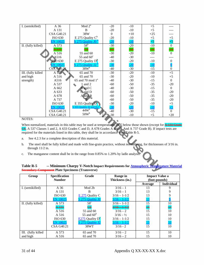
DRAFT - For Committee Use Only
31 of 44 Appendix Q XX-XX-XX X.doc
I. (semikilled) A 36A 131
CSA G40.21ISO 630
EN 10025
Mod 2a
B38W
E 275 Quality Cb
S 275 Quality J0 b
-20-200
-20-20
-10-10+10-10-10
+5+5
+25+5+5
------------+5+5
II. (fully killed) A 573A 131A 516A516
ISO 630EN 10025
CSA G40.21
58b
CS55 and 6055 and 60c
E 275 Quality Db
S 275 Quality J2 b
38Wb
-30-60-30-40-30-30-40
-20-50-20-30-20-20-30
-10-35-10-----10-10-15
0-200
----000
III. (fully killed and high strength)
A 573A 516A516A 537A 662A 633A 678A 737
ISO 630EN 10025
CSA G40.21CSA G40.21
65 and 7065 and 70
65 and 70 mod 1a
1 and 2B and CC and DA and B
BE 355 Quality Db
S 355 Quality J2 and K2 b
44Wb
50Wb
-30-30-40-60-40-60-60-60-30-30-40-30
-20-20-30-50-30-50-50-50-20-20-30-10
-10-10-15-35-15-35-35-35-10-10-15+5
+5+50
-200
-20-20-20+5+50
+20NOTES:
When normalized, materials in this table may be used at temperatures 20°F below those shown (except for A 131 Grade CS, A 537 Classes 1 and 2, A 633 Grades C and D, A 678 Grades A and B, And A 737 Grade B). If impact tests are required for the materials listed in this table, they shall be in accordance with Table R-5.
a. See 4.2.3 for a complete description of this material.
b. The steel shall be fully killed and made with fine-grain practice, without normalizing, for thicknesses of 3/16 in. through 11/2 in.
c. The manganese content shall be in the range from 0.85% to 1.20% by ladle analysis.
Table R-5 -- Minimum Charpy V-Notch Impact Requirements for Atmospheric Temperature MaterialSecondary-Component Plate Specimens (Transverse)
Impact Value a(foot-pounds)
Group Specification Number
Grade Range in Thickness (in.)
Average IndividualI. (semikilled) A 36
A 131ISO 630
EN 10025
Mod 2bB
E 275 Quality CS 275 Quality J0
3/16 – 13/16 – 1
3/16 – 1-1/23/16 – 1-1/2
13131313
9999
II. (fully killed) A 573A 131A 516A 516
ISO 630EN 10025
CSA G40.21
58c
CS55 and 6055 and 60d
E275 Quality Dc
S 275 Quality J238WT
3/16 – 1-1/23/16 – 1-1/2
3/16 – 23/16 – ½
3/16 – 1-1/23/16 – 1-1/2
3/16 - 2
15151515151515
10101010101010
III. (fully killed and high
A 573A 516
65 and 7065 and 70
3/16 – 23/16 – 2
1515
1010

DRAFT - For Committee Use Only
32 of 44 Appendix Q XX-XX-XX X.doc
strength) A 516A 516A 537A 537A 633A 662A 678A 678
ISO 630EN 10025
CSA G40.21A 841
65 and 70 Mod 1b
65 and 70 Mod 2b
12
C and DBAB
E355 Quality Dc
S 355 Quality J2 and K244WT
1
3/16 – 23/16 – 23/16 – 23/16 – 23/16 – 23/16 – 2
3/16 – 1-1/23/16 – 23/16 – 23/16 – 23/16 – 2
1515152015152020151515
1010101510101515101010
NOTES:a. The stated values apply to full-sized specimens. For sub-size specimen acceptance criteria, see ASTM A 20. An impact
test temperature lower than the design metal temperature may be used by the manufacturer, but the impact values at the test temperature must comply with Table R-5. When plate is selected, consideration must be given to the possible degradation of the impact properties of the plate in the weld heat-affected zone.
b. See 4.2.3 for a complete description of this material.
c. The steel shall be fully killed and made with fine-grain practice, without normalizing, for thicknesses of 3/16 in. – 11/2 in.
d. The manganese content shall be in the range from 0.85% to 1.20% by ladle analysis.
R.3 DesignR.3.1 GENERALDesign considerations shall be as specified in API 625, Section 6, “Design and Performance Criteria” together with the additional provisions of this Section R.3.
R.3.2 DENSITY OF LIQUID STOREDThe density of the liquid stored shall be its maximum density within the range of design temperatures, but not less than 36 lbf/ft3.The weight of the liquid stored shall be assumed to be the maximum weight per cubic foot of the specified liquid within the range of operating temperatures, but in no case shall the assumed minimum weight be less than 36 lb/ft3.
R.3.2 DESIGN METAL TEMPERATUREThe design metal temperature of each component exposed to the liquid or vapor being stored shall be the lower of the following:
a. The minimum temperature to which the tank contents will be refrigerated, including the effect of subcooling at reduced pressure.
b. The minimum metal temperature anticipated when the atmospheric temperature is below the refrigerated temperature (see 4.2.1). The effectiveness of the insulation in keeping the metal temperature above the expected minimum atmospheric temperature shall be considered.
R.3.3 DESIGN ALLOWABLE STRESSThe maximum allowable tensile stress shall be taken from Table 5-1 or Table Q-3. For the maximum allowable stresses for
design loadings combined with wind or earthquake loads, see 5.5.6 for carbon steel and Q.3.3.5 for stainless steel and aluminum.
This statement was in R.4 previously and moved to R.3.1 at rev B.
This discussion isincorporated into API 625, section 6.

DRAFT - For Committee Use Only
33 of 44 Appendix Q XX-XX-XX X.doc
R.3.4 PIPINGAll process piping within the limitations of R.1.2 (except pump columns as governed by API 625 7.2.3) shall fulfill the minimum design requirements of ASME B31.3 but using the allowable stresses of Table 5-1.
R.3.5 ANNULAR BOTTOM PLATES FOR PRIMARY AND SECONDARY LIQUID CONTAINERSR.3.5.1 The tank shell that contains the liquid Primary liquid containers and secondary liquid containers shall have butt-welded annular bottom plates with a radial width that provides at least 24 in. between the inside of the shell and any lap-welded joint in the remainder of the bottom and at least a 2-in. projection outside the shell. A greater radial width (Lmin) of annular plate is required when calculated by the following equation:
Lmin = 390 tb / sqrt[(H)(G)]
where
tb = nominal thickness of the annular plate, in in.,
H = design maximum height of the liquid, in ft,
G = design specific gravity of the liquid to be stored (see R.3.2).
R.3.5.2 The thickness of the annular bottom plates shall be not less than the thicknesses listed in Table R-6.
R.3.5.3 The ring of annular plates shall have a circular outside circumference, but may have a regular polygonal shape inside the tank shell with the number of sides equal to the number of annular plates. These pieces shall be butt-welded in accordance with R.5.1.1, item a b.
R.3.5.4 The plates of the first shell course shall be attached to the annular bottom plates by welds as required by 5.9.5 except when a full penetration weld is used or required (see R.5.1.1).
R.3.5.5 Butt-welds in annular plates shall be not closer than 12 in. from any vertical weld in the tank shell.
R.3.5.6 Three-plate laps or butt-weld junctions in the tank bottom shall be not closer than 12 in. from each other. and/or the butt-welds of the annular plate.
Table R-6 -- Thickness Requirementsa for the Annular Bottom Plate (in.)Design Stressb in First Shell Course
(psi)Nominal Thickness
of First ShellCourse (in.) • 20,000 22,000 24,000 26,000
• 0.75> 0.75 – 1.00> 1.00 – 1.25> 1.25 – 1.50
1/41/41/41/4
1/41/41/4
9/32
1/41/4
5/163/8
1/45/163/8
7/16NOTES:
a. The thicknesses and width (see R.3.5.1) are based on the foundation providing a uniform support under the full width of the annular plate. Unless the foundation is properly compacted, particularly at the inside of a concrete ringwall, settlement will produce product additional stresses in the annular plate.
b. The stress shall be calculated using the formula (2.6D)(HG)/t, where D = nominal diameter of the tank, in ft; H = maximum filling height of the tank for design, in ft; G = design specific gravity; and t = design thickness of the first shell course, excluding corrosion allowance, in.
Fixing typo that
resulted from 620-
293

DRAFT - For Committee Use Only
34 of 44 Appendix Q XX-XX-XX X.doc
R.3.6 SHELL STIFFENING RINGS FOR PRIMARY AND SECONDARY LIQUID CONTAINERS TANKS THAT CONTAIN LIQUIDR.3.6.1 Internal or external shell stiffening rings may be required to maintain roundness when the tank is subjected to wind, vacuum, or other specified loads. When stiffening rings are required, the stiffener-to-shell weld details shall be in accordance with Figure R-1 and R.3.6.2 through R.3.6.5.
R.3.6.2 The stiffener ring and backing strip, if used, are primary components, and they shall comply with the requirements of R.2.1. The stiffener ring may be fabricated from plate using an intermittent weld on alternating sides between the web and the flange.
R.3.6.3 One rat hole with a minimum radius of 3/4 in. shall be provided at each longitudinal shell joint and ring juncture weld (see Figure R-1).
R.3.6.4 All fillet welds shall consist of a minimum of two passes. The ends of the fillet welds shall be 2 in. from the rat hole (see Figure R-1), and these welds shall be deposited by starting 2 in. from the rat hole and welding away from the rat hole. An acceptable alternative to stopping fillet welds 2 in. short of the rat hole would be to weld continuously through the rat hole from one side of the stiffener to the opposite side. All craters in fillet welds shall be required by back welding.
R.3.6.5 Any joints between the adjacent sections of stiffening rings, as shown in Figure R-1, shall be made so that the required moment of inertia of the combined ring-shell section is provided. Weld joints between adjacent sections shall be made with full-thickness and full-penetration butt-welds. Stiffening-ring butt-welds may employ metal backing strips. Backing strips and the associated welding shall be made in a manner that provides a smooth contour in the rat hole and all other weld joints ends. All weld passes shall be started at the rat hole and other weld joint ends and shall be completed by moving away from these ends. Passes shall be overlapped away from the edge to provide a smooth continuous weld.
R.3.7 TANK ANCHORAGE FOR PRIMARY AND SECONDARY LIQUID CONTAINERSR.3.7.1 In addition to the loads in R.4, R.5.1, and R.5.2, the anchorage for the primary liquid container and any secondary liquid container tank that contains liquid, whether it be a single-wall tank or the inner tank of a double-wall tank, shall be designed to meet the requirements of R.3.7.2 through R.3.7.5.
R.3.7.2 The anchorage shall accommodate movement of the tank wall and bottom caused by thermal changes.
R.3.7.3 The manufacturer and the purchaser shall either use should consider using stainless steel anchorage materials, or they should provide for corrosion allowance when carbon steels are used. Material for tank anchorage shall meet the requirements for primary components given in R.2.1.
R.3.7.4 For anchored flat-bottom tanks, the aAnchorage subject to load from internal pressure shall be designed as described in R.3.7.4.1 through R.3.7.4.3.
R.3.7.4.1 When the topshell course is the minimum thickness indicated in Table 5-6, the minimum anchorage shall be designed for normal loads as specified by the purchaser and by this standard. See 5.11.2.3 for the allowable stress.
R.3.7.4.2 When the topshell course is thickened beyond minimum thickness provided in Table 5-6 or as in Figure 5-6, details f and g, or a knuckle is used, the minimum anchorage shall be designed for three times the internal design pressure. The allowable stress for this loading is 90% of the minimum specified yield strength of anchorage material.
R.3.7.4.3 As an alternative to R.3.7.4.2, the purchaser may specify a combination of normal anchorage design, (see R.3.7.4.1) and emergency venting. The purchaser shall specify required emergency or upset condition venting discharge rates (see 9.2 and K.1).”R.3.7.5 The foundation design loading for R.3.7.4 is described in R.8.5.3.
R.3.8 COMBINATION OF DESIGN LOADS FOR DOUBLE-WALL TANKSThe inner and outer containers shall be designed for the most critical load combinations per 5.4.2 and per R.3.8.1 through R.3.8.5 as applicable.
R.3.8.1 Inner Tank
R.3.8 was moved from R.5.2

DRAFT - For Committee Use Only
35 of 44 Appendix Q XX-XX-XX X.doc
The primary liquid container (inner tank) shall also be designed for the most critical combinations of loading that result from internal pressure and liquid head, the static insulation pressure, the insulation pressure as the inner tank expandsduring warming after an in-service period, and the purging or operating pressure of the space between the inner and outer tank shells, unless the pressure is equalized on both sides of the inner tank. The outer wall shall be designed for the purging and operating pressure of the space between the inner and outer tank shells and for the loading for insulation, the pressure of wind forces, and roof loading,
R.3.8.2 Single Containment Outer Wall
A metallic warm vapor, or purge gas container for a double wall, single containment tank system shall also be designed for the purging and operating pressure of the space between the inner and outer tank shells and for the loading from the insulation.
R.3.8.3 Double Containment Outer Wall
A metallic warm vapor, purge gas, or secondary liquid container for a double containment tank system shall be designed for the load combinations specified for the outer wall of a single containment tank system. A metallic secondary liquid container shall also be designed for the following upset conditions:
a. Dead load and liquid head [ DL + PL ]
b. Dead load, liquid head, and seismic [ DL + P L + E ]
where DL , P L & E are defined in R.3.8.5
R.3.8.4 Full Containment Outer Wall
A metallic outer wall for a full containment tank system shall be designed for the load combinations specified for the outer wall of a single containment tank system. The metallic outer wall shall also be designed for the following upset conditions:
a. Dead load, design pressure and liquid head [ DL + Pg + PL ]
b. Dead load, design pressure, liquid head, and seismic [ DL + Pg + P L + E ]
where DL , Pg, P L & E are defined in R.3.8.5:
R.3.8.5 Nomenclature
DL = Dead load
Pg = Design pressure of the secondary liquid container
PL = Liquid head in the secondary liquid container determined from the maximum normal operating capacity of the primary liquid container
E = ALE seismic as required by L.4. including 10% snow load
R.3.9 WARM VAPOR AND PURGE GAS CONTAINERS OUTER TANKR.3.9.1 Design of warm vapor and purge gas containers shall be in accordance with Section 5 of this standard ) together with the additional provisions of this Section R.3.9.
R.3.9.2 The outer bottom, shell, and roof Warm vapor and purge gas containers shall have a minimum nominal thickness of 3•16 in.
R.3.9.3 The outer tank bottom, shell, and roof not in contact with the vaporized liquefied gas Purge gas containers may be of single-welded lap or of single-welded partial penetration butt construction when the thickness does not exceed 3/8 in. Such single side welds shall be made from the outside to prevent corrosion and the entrance of moisture. At any thickness, it may be of single-welded butt construction from either side with full penetration and fusion or double-welded butt construction without necessarily having full fusion and penetration.
R.3.9.4 When in contact with the vaporized liquefied gas, the outer tank bottom, shell, and roof Warm vapor containersshall conform to the lap- or butt-welded construction described elsewhere in this standard.
R.3.9 was moved from R.5.3

DRAFT - For Committee Use Only
36 of 44 Appendix Q XX-XX-XX X.doc
R.4 Design of a Single-Wall TankThe purchaser shall specify the design metal temperature and pressures (internal and external), specific gravity of the contents to be stored, roof live load, wind load, earthquake load where applicable, and corrosion allowance, if any. The insulation load shall be considered.
R.5 Design of a Double-Wall TankR.5.1 DESIGN SPECIFICATIONS The outer bottom, shell, and roof of a double-wall tank shall enclose an insulating space around the bottom, shell, and roof of the inner tank that contains the stored liquid. The annular space shall be maintained at a low positive pressure, which necessitates that the enclosure be vaportight. The purchaser shall specify the design metal temperature and pressures (internal and external) of both the inner and outer tanks, specific gravity of the contents to be stored, roof live load, wind load, earthquake load where applicable, and corrosion allowance, if any. The static insulation pressure and pressures from expansion and contraction of the insulation shall be considered.
R.5.2 COMBINATION OF DESIGN LOADSThe inner tank shall be designed for the most critical combinations of loading that result from internal pressure and liquid head, the static insulation pressure, the insulation pressure as the inner tank expands after an in-service period, and the purging or operating pressure of the space between the inner and outer tank shells. The outer wall shall be designed for the purging and operating pressure of the space between the inner and outer tank shells and for the loading for insulation, the pressure of wind forces, and roof loading,
R.5.3 OUTER TANK R.5.3.1 The outer bottom, shell, and roof shall have a minimum nominal thickness of 3•16 in.
R.5.3.2 The outer tank bottom, shell, and roof not in contact with the vaporized liquefied gas may be of single-welded lap or of single-welded butt construction when the thickness does not exceed 3/8 in.; or, at any thickness, it may be of double-welded butt construction without necessarily having full fusion and penetration. Single-welded joints shall be welded from the outside to prevent corrosion and the entrance of moisture.
R.5.3.3 When in contact with the vaporized liquefied gas, the outer tank bottom, shell, and roof shall conform to the lap-or butt-welded construction described elsewhere in this standard.
R.4 Welding ProceduresThese rules shall apply to primary and secondary liquid containers, refrigerated temperature roofs and suspended
insulation decks. only to the primary components of the tank. The secondary components Warm vapor and purge gas containers shall be welded in accordance with the basic rules of this standard.
R.4.1 WELDING PROCEDURE QUALIFICATION
R.4.1.1 The qualification of welding procedures shall conform to 6.7. For primary components product temperature materials (see R.2.1), impact tests are also required for each welding procedure (with exceptions for Type 304 or 304L stainless steel described in Table R-1, Note 2). Charpy V-notch specimens that conform to ASTM E 23 shall be taken from the weld metal and from the heat-affected zone of the welding procedure qualification test plates or duplicate test plates.
R.4.1.2 Weld metal impact specimens shall be taken across the weld with the notch in the weld metal. The specimen shall be oriented so that the notch is normal to the surface of the material. One face of the specimen shall be substantially parallel to and within 1•16 in. of the surface.
R.5.2 was moved to R.3.8
R.5.3 was moved to R.3.9
Former 620 R.4 and Q.5.1 are higher level “tank system” discussions which are now covered with greater detail in API 625, section4 for purchaser specified information, section 5 for tank system configurations, and 6.3.6 for design temperature.
DRAFT - For Committee Use Only
37 of 44 Appendix Q XX-XX-XX X.doc
R.4.1.3 Heat-affected-zone impact specimens shall be taken across the weld and as near the surface of the material as is practicable. The specimens shall be of sufficient length to locate, after etching, the notch in the heat-affected zone. The notch shall be cut approximately normal to the material surface to include as much heat-affected zone material as possible in the resulting fracture.
R.4.1.4 Impact test specimens shall be tested at the design metal temperature or at a lower temperature, as agreed upon by the purchaser and the manufacturer.
R.4.1.5 The required impact values of the weld and heat-affected zone shall be as given in Table R-2.
R.4.2 PRODUCTION WELDING PROCEDURES
The production welding procedures and the production welding shall conform to the requirements of the procedure qualification tests within the following limitations:
a. Individual weld layer thickness shall not be substantially greater than that used in the procedure qualification test.
b. Electrodes shall be of the same size and American Welding Society (AWS) classification.
c. The nominal preheat and interpass temperatures shall be the same.
R.4.3 PRODUCTION WELD TESTSR.4.3.1 Production weld test plates shall be welded and tested for primary and secondary liquid container primary-component, butt-welded shell plates. The number of production weld tests shall be based on the requirements of R.4.3.3 and R.4.3.4. Weld testing shall be in accordance with R.4.3.5. Test plates shall be made from plates produced only from the heats used to produce the shell plates for the tank.
R.4.3.2 Test plates shall be welded using the same qualified welding procedure and electrodes as required for the tank shell plate joints. The test plates need not be welded as an extension of the tank shell joint but shall be welded in the required qualifying positions.
R.4.3.3 One test weld shall be made on a set of plates from each specification and grade of plate material, using a thickness that would qualify for all thicknesses in the shell. Each test welded of thickness t shall qualify for plate thicknesses from 2t down to t/2, but not less than 5•8 in. For plate thicknesses less than 5•8 in., a test weld shall be made for the thinnest shell plate to be welded; this test weld will qualify the plate thickness from t up to 2t.
R.4.3.4 Test welds shall be made for each position and for each process used in welding primary and secondary liquid containers’ shell plates tank shell except for the following:
a) A manual or semi-automatic vertical test weld will qualify manual or semi-automatic welding using the same weld process in all positions. b) A semi-automatic vertical test weld will qualify machine welding using the same weld process in all positions.c) Test welds are not required for machine welded circumferential joints in cylindrical shells.
R.4.3.5 The impact specimens and testing procedure shall conform to R.4.1.2 through R.4.1.5.
R.4.3.6 By agreement between the purchaser and the manufacturer, production weld test plates for the first tank shall satisfy the requirements of this paragraph for similar tanks at the same location if the tanks are fabricated within six months of the time the impact tests were made and found satisfactory and the same weld procedure specifications are used.
R.5 Requirements for Fabrication, Openings, Examination and Testingand InspectionR.5.1 WELDING OF PRIMARY COMPONENTS MISCELLANEOUS REQUIREMENTS FOR PRIMARY AND SECONDARY LIQUID CONTAINERS AND REFRIGERATED TEMPERATURE ROOFS

DRAFT - For Committee Use Only
38 of 44 Appendix Q XX-XX-XX X.doc
R.5.1.1 The following primary components shall be joined with double butt-welds that have complete penetration and complete fusion except as noted:
a. Longitudinal and circumferential shell joints and joints that connect the annular bottom plates together. When approved by purchaser, these may be welded from a single side provided temporary non-fusible backing is used with complete penetration and complete fusion. Both sides of the joint shall be 100% visually examined as specified in 7.15.5.
b. Joints that connect sections of compression rings and sections of shell stiffeners together. Backup bars may be used for these joints with complete penetration and complete fusion detail.
c. Joints around the periphery of a shell insert plate.
d. Joints that connect the shell to the bottom, unless a method of leak checking is used (see R.6.2.3), in which case double fillet welds are acceptable.
e. Joints that connect nozzle and manhole necks to flanges.
f. Butt-welds in piping nozzles, manway necks, and pipe fittings, including weld neck flanges, shall be made using double butt-welded joints. When accessibility does not permit the use of double butt-welded joints, single butt-welded joints that ensure full penetration through the root of the joint are permitted.
R.5.1.2 All primary components joined together by fillet welds shall have a minimum of two passes.
R.5.1.3 Slip-on flanges may be used where specifically approved by the purchaser.
R.5.2 WELDING OF CONNECTIONS IN PRIMARY AND SECONDARY LIQUID CONTAINERS AND REFRIGERATED TEMPERATURE ROOFS PRIMARY COMPONENTS
R.5.1.4 All opening connections located in primary components shall have complete penetration and complete fusion. Acceptable types of welded opening connections are shown in Figure 5-8, panels a, b, c, g, h, m, and o.
R.5.2.1 All connections shall have complete penetration and complete fusion.
R.5.2.2 Acceptable types of welded opening connections are shown in Figure 5-8, panels a, b, c, g, h, m, and o.
R.5.2.3 Flanges for nozzles shall be in accordance with this standard; however, the material shall comply with the requirements of R.2.1.
R.5.2.4 Manways shall have welded closures rather than depending on gaskets.
R.5.3 POSTWELD HEAT TREATMENTR.5.3.1 In primary components, All primary and secondary liquid container opening connections shall be welded into the shell plate or a thickened insert plate, and the welded assembly shall be stress relieved prior to installation in the tank unless one of the following exceptions is fulfilled:
a. The stress level in the plate, under the design conditions, does not exceed 10% of the minimum tensile strength of the plate material. The opening shall be reinforced for the low stress.
b. The impact tests on the material and welding fulfill the requirements of R.2.1.2 and Table R-2, and the thickness of the material is less than 5•8 in. for any diameter of connection or less than 11•4 in. for connections that have a nominal diameter less than 12 in. The thickness of the nozzle neck without stress relief shall be limited to the value of (D + 50)/120, as described in 5.25.3.
c. Opening reinforcement is made from forgings similar in configuration to Figure 5-8, panels o-1, o-2, o-3, and o-4.
R.5.3.2 The stress-relieving requirements of 5.25 shall still be mandatory for both primary and secondary components.
R.5.3.3 When used in stress relieved assemblies, the material of TMCP steel A 841 shall be represented by test specimens that have been subjected to the same heat treatment as that used for the stress relieved assembly.
R.5.4 SPACING OF CONNECTIONS AND WELDS
R.5.2 restructured to match Q.5.1.4

DRAFT - For Committee Use Only
39 of 44 Appendix Q XX-XX-XX X.doc
R.5.4.1 In primary and secondary liquid containers primary components, all opening connections in a shell plate shall conform to the requirements of R.5.4.1 through R.5.4.3 for the spacing of butt and fillet welds.
R.5.4.2 The butt-weld around the periphery of a thickened insert plate or the fillet weld around the periphery of a reinforcing plate shall be at least the greater of 10 times the shell thickness or 12 in. from any butt-welded shell seams except where the completed periphery weld has been stress relieved prior to the welding of the adjacent butt-welded shell seams. Where stress relief has been performed, the spacing from the periphery weld to a shell butt-weld shall be at least 6 in. from the longitudinal or meridional joints or 3 in. from the circumferential or latitudinal joints if in either case the spacing is not less than 3 times the shell thickness. These rules shall also apply to the bottom-to-shell joint; however, as an alternative, the insert plate or reinforcing plate may extend to and intersect the bottom-to-shell joint at approximately 90°. The stress-relieving requirements do not apply to the weld to the bottom or annular plate.
R.5.4.3 In cylindrical tank walls, the longitudinal weld joints in adjacent shell courses, including compression ring welds, shall be offset from each other a minimum distance of 12 in.
R.5.4.4 Radial weld joints in a compression ring shall not be closer than 12 in. from any vertical weld.
R.5.5 INSPECTION EXAMINATION OF WELDS BY MAGNETIC-PARTICLE OR LIQUID-PENETRANT METHODS
R.5.5.1 The following primary and secondary liquid container primary-component welds shall be inspected examined, using the magnetic-particle method (see 7.15) for carbon steel and the liquid-penetrant method (see 7.15) for stainless steel, after stress relieving, if any, and before the hydrostatic test of the tank.
a. All longitudinal and circumferential butt-welds that are not completely radiographed. Inspection Examination shall be on both sides of the joint.
b. The welded joint that joins the cylindrical wall of the tank to the bottom annular plates.
c. All welds of opening connections that are not completely radiographed, including nozzle and manhole neck welds and neck-to-flange welds. Inspection Examination shall also include the root pass and every 1•2 in. of thickness of deposited weld metal (see 5.27.11) as welding progresses.
d. All welds of attachments to primary components such as stiffeners, compression rings, clips, and other nonpressure parts.
e. All welded joints on which backing strips are to remain shall also be inspected examined after the first complete layer (normally two beads) two layers (or beads) of weld metal have been deposited.
R.5.5.2 All longitudinal and circumferential butt-welds in thermal distance pieces connecting cold piping to warm vapor or purge gas containers shall also be examinined by the liquid-penetrant method
R.5.6 RADIOGRAPHIC INSPECTION EXAMINATION OF BUTT-WELDS IN PLATESPrimary and secondary liquid container Primary-component butt-welds shall be examined by radiographic methods as listed in R.5.6.1 through R.5.6.6.
R.5.6.1 Butt-welds in all tank wall courses subjected to a maximum actual operating membrane tensile stress perpendicular to the welded joint that is greater than 0.1 times the specified minimum tensile strength of the plate material shall be completely radiographed.
R.5.6.2 Butt-welds in all tank wall courses subjected to a maximum actual operating membrane tensile stress perpendicular to the welded joint that is less than or equal to 0.1 times the specified minimum tensile strength of the plate material shall be radiographed in accordance with Figure R-2.
R.5.6.3 Butt-welds around the periphery of a thickened insert plate shall be completely radiographed. This does not include the weld that joins the insert plate with the bottom plate of a flat-bottom tank.
R.5.6.4 Butt-welds at all three-plate junctions in the tank wall shall be radiographed except in the case of a flat bottom (wall) supported uniformly by the foundation. This does not include the shell-to-bottom weld of a flat-bottom tank. See Figure R-2 for minimum exposure dimensions.

DRAFT - For Committee Use Only
40 of 44 Appendix Q XX-XX-XX X.doc
R.5.6.5 Twenty-five percent of the butt-welded annular plate radial joints shall be spot radiographed for a minimum length of 6 in. The location shall be under the tank shell at the outer edge of the joint.
R.5.6.6 Twenty-five percent of the butt-welded compression bar radial joints shall be spot radiographed for a minimum length of 6 in. except as required by 5.26.3.3.
R.5.7 INSPECTION EXAMINATION OF BUTT-WELDS IN PIPINGR.5.7.1 Butt-welds in piping and in pipe fittings within the limitations of 1.3.2, including the annular space of double-wall tanks API 625, Section 1.6 , shall be inspected examined in conformance with R.5.7.2 through R.5.7.9.
R.5.7.2 Longitudinal welded joints in piping carrying that contains liquid shall be completely radiographed except for welds in manufactured pipe welded without filler metal, 12 in. or less in diameter, which is tested hydrostatically or by eddy current to ASTM requirements.
R.5.7.3 Longitudinal welded joints in piping carrying that contains vapor shall be completely radiographed except for welds in manufactured pipe welded without filler metal, 18 in. or less in diameter, which is tested hydrostatically or by eddy current to ASTM requirements.
R.5.7.4 Ten percent of the circumferential welded joints (including weld neck flange to pipe joints) in liquid and vapor carrying all piping shall be completely radiographed.
R.5.7.5 Butt-welded joints used to fabricate tank liquid and vapor carrying built-up pipe fittings shall be completely radiographed.
R.5.7.6 Lines carrying liquid located outside the primary liquid container in double wall tanks shall be hydrostatically or pneumatically pressurized at a minimum pressure of 35 lbf/in.2 and butt welded joints shall be simultaneously visually examined (hydrostatic) or solution film tested (pneumatic) for tightness. If manufactured pipe has been hydrostatically tested previously to ASTM requirements, then only circumferential welds need to be examined.
R.5.7.7 Lines carrying product vapor within a purge gas container’s annular space shall be pneumatically pressurized at a minimum pressure of 5 lbf/in2 and circumferential butt welded joints shall be simultaneously solution film tested for tightness.
R.5.7.8 For piping that does not carry liquid or product vapor (e.g. instrument conduit and purge lines) examination needs to satisfy only the applicable requirements of R.2.
R.5.7.9 Radiography of butt welds in piping shall comply with ASME B31.3 Process Piping rules, Normal Fluid Service conditions.
R.5.8 NONPRESSURE PARTSWelds for pads, lifting lugs, and other nonpressure parts, as well as temporary lugs for alignment and scaffolding attached to primary and secondary liquid containers primary components, shall be made in full compliance with a welding procedure qualified in accordance with R.4.1. Lugs attached for erection purposes shall be removed by the grinding of all remaining welds followed by magnetic-particle examination. Plate that is gouged or torn in removing the lugs shall be repaired using a qualified procedure, followed by grinding. Where such repairs are made in primary and secondary liquid containers components, the area shall be inspected examined using the magnetic-particle method. A visual inspectionexamination is adequate for repaired areas in warm vapor and purge gas containers secondary components.
R.6 Testing the Primary Liquid and Primary Vapor Containers Tank In Contact With The Refrigerated Product
The provisions stated in R.6.1 through R.6.3 this section are testing requirements for the primary liquid container. tank refrigerated by the liquid contents. Provisions stated noted in R.6.4 R.7 cover the pneumatic testing of the warm vapor container (or when inner tank is not open top, the refrigerated temperature roof). outer tank, which is not in contact with the refrigerated liquid and is subject to a higher temperature that approaches atmospheric.
DRAFT - For Committee Use Only
41 of 44 Appendix Q XX-XX-XX X.doc
Figure R-2—Radiographic Requirements for Butt-Welded Shell Joints in Cylindrical Flat-Bottom Tanks
R.6.1 GENERAL PROCEDUREA thorough check for tightness and structural adequacy is essential for the primary liquid container a single-wall tank or for the inner tank of a double-wall tank. Except as permitted by R.6.5, the test shall be conducted after the entire tank is complete, but before the insulation is applied. The hydrostatic test shall be performed by filling the tank with water to the design liquid level and applying an overload air pressure of 1.25 times the pressure for which the vapor space is designed. The hydrostatic test shall not produce a membrane tensile stress in any part of the tank exceeding 85% of the minimum specified yield strength or 55% of the minimum specified tensile strength of the material.
R.6.2 TEST PRELIMINARIESBefore the tank is filled with water, the procedures described in R.6.2.1 through R.6.2.5 shall be completed.
R.6.2.1 All welded joints in the bottom of the tank shall be inspected examined by applying a solution film to the welds and pulling a partial vacuum of at least 3 lbf/in.2 gauge above the welds by means of a vacuum box with a transparent top.
R.6.2.2 Complete penetration and complete fusion welds that join the cylindrical wall to the tank bottom shall be inspectedexamined by applying a solution film to the welds and pulling a partial vacuum of at least 3 lbf/in.2 gauge above the welds by means of a vacuum box with a transparent top.
R.6.2.3 When the weld in R.6.2.2 does not have complete penetration and complete fusion, the initial weld passes, inside and outside of the shell, shall have all slag and non-metals removed from the surface of the welds and the welds examined visually. After completion of the inside and outside fillet or partial penetration welds, the welds shall be tested by pressurizing the volume between the inside and outside welds with air pressure to 15 lbf/in.2 gauge and applying a solution film to both welds. To assure that the air pressure reaches all parts of the welds, a sealed blockage in the annular passage between the inside and outside welds must be provided by welding at one or more points. Additionally, a small pipe coupling communicating with the volume between the welds must be welded on each side of and adjacent to the blockages. The air supply must be connected at one end and a pressure gauge connected to a coupling on the other end of the segment under test.
R.6.2.4 The attachment welding around all reinforced openings and their reinforcements in the bottom, shell, and roof shall be examined by magnetic particle method and solution film test in accordance with 7.18.2.2 and 7.18.2.3 inspected by applying air pressure of 15 lbf/in.2 gauge behind the reinforcement plates and simultaneously applying a solution film to the welds. The test holes in the reinforcing plates shall be left open.
R.6.2.5 The attachment fillet welds around bottom openings, which do not permit the application of air pressure behind the reinforcing plate, shall be inspected examined by applying a solution film and by a vacuum box inspection examination.
R.6.3 HYDROSTATIC TESTThe provisions described in R.6.3.1 through R.6.3.5 shall apply during and after water filling for the hydrostatic test.
R.6.3.1 The tank shall be vented to the atmosphere when it is filled with or emptied of water.
R.6.3.2 During water filling, the elevations of at least eight four equidistant points at the bottom of the tank shell and on top of the ringwall or slab shall be checked. Differential settlement, or uniform settlement of substantial magnitude, requires an immediate stop to water filling. Any further filling with water will depend on an evaluation of the measured settlement.
R.6.3.3 The tank shall be filled with water to the design liquid level.
R.6.3.4 After the tank is filled with water and before the pneumatic test pressure is applied, anchor bolts or anchor straps, if provided, shall be tightened against the hold-down brackets.
R.6.3.5 All welds in the shell, including the corner weld between the shell and the bottom, shall be visually checked for tightness.
R.6.4 PNEUMATIC PRESSURE

DRAFT - For Committee Use Only
42 of 44 Appendix Q XX-XX-XX X.doc
R.6.4.1 An air pressure equal to 1.25 times the pressure for which the vapor space is designed shall be applied to the enclosed space above the water level. In the case of a double-wall tank with an open-top inner tank, where the air pressure acts against the outer tank and the inner tank is thus not stressed by the air pressure, the inner tank may be emptied of water before the pneumatic pressure testing begins.
R.6.4.2 The test pressure shall be held for 1 hour.
R.6.4.3 The air pressure shall be reduced until the design pressure is reached.
R.6.4.4 Above the water level, all welded joints shall be checked with a solution film. A prior vacuum box check may be substituted for the solution-film inspection examination of the welded joints. Above the water level, the solution-film inspection examination shall be made, of all welds around openings, all piping joints, and the compression ring welds to the roof and shell except any listed below:
• Continuous double lap roof to compression ring welds • Shell to compression ring welds, continuous inside and outside, and applying a thickened upper shell ring detail
similar to figure 5-6 details f or f-1 The thickened upper shell ring shall be greater than ½ of the conical compression ring thickness and greater than two times the adjacent shell ring thickness.
• Full fusion butt welded connections
R.6.4.5 The opening pressure or vacuum of the pressure relief and vacuum relief valves shall be checked by pumping air above the water level and releasing the pressure, then partially withdrawing water from the tank.
R.6.4.6 After the tank has been emptied of water and is at atmospheric pressure, the anchorage, if provided, shall be rechecked for tightness against the hold-down brackets.
R.6.4.7 Air pressure equal to the design pressure shall be applied to the empty tank, and the anchorage, if provided, and the foundation shall be checked for uplift.
R.8.5 TEMPORARY OPENINGS AFTER HYDROSTATIC TEST
When approved by the purchaser in writing, and only in the case of tanks which when complete have no shell penetrations, it is permitted to restore by welding up to four temporary shell openings after the hydrostatic test in accordance with the provisions of this section.
R.8.5.1 Each temporary opening shall be restored by the insertion of a shell plate which matches the thickness and specification of adjacent shell material and is welded into place with full fusion butt welds. The insert plate shall be round with diameter no less than 24” and no greater than 42”.
R.8.5.2 The insert plate weld shall not cross any shell seams and shall be at least the greater of 10 times the shell thickness or 12 in. from any other weld in the shell including shell seams, shell-to-bottom weld or attachment welds.
R.8.5.3 The butt weld around the periphery of the plate shall be examined over 100% of its length by the magnetic particle method, by the radiographic method and by the ultrasonic method. Ultrasonic examination acceptance criteria shall be as given in Table U-1. The magnetic particle examination is required on the root pass, on the backgouged surface, and on the inside and outside finished weld surfaces. Additionally, the weld shall be vacuum box leak tested.
R.7 Testing a Purge Gas Container The Outer Tank of a Double-Wall Refrigerated TankR.7.1 The tightness test shall be made before insulation is installed.
R.7.2 The inner tank shall be opened to the atmosphere, and a sufficient amount of water shall be added to the inner tank to balance the upward pressure against the inner tank bottom produced by the pneumatic test of the outer tank; as an alternative, the pressure between the inner and outer tanks can be equalized.
R.7.3 Air pressure shall be applied to the space enclosed by the outer tank equal to at least the design gas pressure but not exceeding a pressure that would overstress either the inner or outer tank.
R.7.4 While the test pressure is being held, all lap welded seams and all welds in connections in the outer shell and roof shall be thoroughly inspected examined with solution film unless they were previously checked with a vacuum box.
Passed to publicatio
n item 620-295 is incorporat
ed

DRAFT - For Committee Use Only
43 of 44 Appendix Q XX-XX-XX X.doc
R.7.5 The air pressure shall be released.
R.7.6 Pressure relief and vacuum relief valves shall be checked by applying the design gas pressure to the outer tank, followed by evacuation of the outer space to the vacuum setting of the relief valve.
R.8 FoundationsR.8.1 Foundations shall be in accordance with API 625, Section 6.6.
R.8.1 GENERAL
R.8.1.1 Appendix C describes the factors involved in obtaining adequate foundations for tanks that operate at atmospheric temperature. The foundations for refrigerated tanks are more complicated because of the thermal movement of the tank, the insulation required for the bottom, the effects of foundation freezing and possible frost heaving, and the anchorage required to resist uplift.
R.8.1.2 The services of a qualified foundation engineer are essential. Experience with tanks in the area may provide sufficient data, but normally a thorough investigation, including soil tests, would be required for proper design of the foundation.
R.8.2 TYPES OF FOUNDATIONS
The nature of the soil, bearing capacity, and predicted settlement are factors that lead to a choice of foundations. At questionable sites where large settlements are anticipated, or where clay soils may be subjected to continual consolidation over long periods of time, a concrete slab supported by piling should be considered. Where anticipated settlements are acceptable and where the soil provides adequate bearing capacity, a ringwall-type foundation with compacted material within the ringwall is usually acceptable. A ringwall serves two purposes. It encloses the compacted material under the tank and provides a weight that, when anchor bolts are attached to the shell, resists any uplifting tendency of the shell under internal pressure and under wind or earthquake loads.
R.8.3 BEARING ON FOUNDATIONS
Foundations shall be designed to resist the load exerted by the tank and its contents when the tank is filled with water to the design liquid level. Foundations shall be designed for at least the maximum operating conditions including the wind or earthquake loads. Under water test, the total load on the foundation shall not exceed 125% of the allowable loading.
R.8.4 UPLIFTING FORCE AND DOWNWARD WEIGHTS
The uplifting force to be considered in designing the ringwall or concrete pad foundation may be offset by the coexistent downward weights and forces, including the metal and insulation weight of the shell and roof, and the concrete and earth weight transmitted by the anchorage to the shell. The tank shall be assumed to be empty of liquid.
R.8.2 UPLIFT ON FOUNDATION
R.8.2.1 The increased uplift described in R.8.2.2 R.8.4.2 and R.8.2.3 R.8.4.3 is intended to apply to the size of the ringwall and foundation but not to the anchorage.
R.8.2.2 For tanks with an internal design pressure less than 1 lbf/in.2 gauge, the uplift shall be taken as the smaller of the maximum uplift values computed under the following conditions:
a. The internal design pressure times 1.5 plus the design wind load on the shell and roof.
b. The internal design pressure plus 0.25 lbf/in.2 gauge plus the design wind load on the shell and roof.
R.8.2.3 For tanks with an internal design pressure of 1 lbf/in.2 gauge and over, the uplift, if any, shall be calculated under the combined conditions of 1.25 times the internal design condition plus the design wind load on the shell and roof.
R.8.2.4 When the anchorage is designed to meet the requirements of R.3.7.4.2 R.3.6.4.2, the foundation should be designed to resist the uplift that results from three times the design pressure with the tank full to the design liquid level. When designing to any of the conditions of this paragraph, it is permissible to utilize friction between the soil and the vertical face of the ringwall and all of the effective liquid weight.
Text on Uplift
restored since it did not fit into API 625 as
once thought it
would.

DRAFT - For Committee Use Only
44 of 44 Appendix Q XX-XX-XX X.doc
R.9 MarkingExcept for 8.2 on Division of Responsibility, marking requirements of Section 8 are superseded by the requirements of API 625, Section 11
R.9.1 DATA ON NAMEPLATE
The data required to be marked on the tank by the manufacturer is listed in 8.1.
R.9.2 LOCATION OF NAMEPLATE
In addition to the requirements of 8.1, the nameplate shall be attached to the tank at an accessible location but shall be outside of any insulation or protective covering of the tank. The nameplate for the inner tank shall be located on the outer tank wall but shall refer to the inner tank. The nameplate, if any, for the outer tank of a double-wall tank shall be located adjacent to the nameplate for the inner tank and shall refer to the outer tank.