
Rufus et al. World Journal of Engineering Research and Technology
www.wjert.org
322
SIMULATION MODELLING ANALYSIS OF SHELL AND TUBE HEAT
EXCHANGER
Rufus Ogbuka Chime*1, Momoh Abdullah Yakubu
2, Echegi Christian Uche
3
1Mechanical Engineering Institute of Management and Technology IMT Enugu.
2Advanced Manufacturing Process Scientific Equipment Development Institute Enugu.
3Chemical Engineering Institute of Management and Technology IMT Enugu.
Article Received on 27/07/2018 Article Revised on 17/08/2018 Article Accepted on 06/09/2018
ABSTRACT
Simulation is the imitation of the operation of a real-world process or
system over time. The act of simulating something first requires that a
model be developed; this model represents the key characteristics or
behaviors of the selected physical or abstract system or process. The
model represents the system itself, whereas the simulation represents
the operation of the system over time. Modelling is about building representations of things
in the real world and allowing ideas to be investigated; it is central to all activities in the
process for building or creating an artefact of some form or other. In effect, a model is a way
of expressing a particular view of an identifiable system of some kind. Analysis is the process
of breaking a complex topic or substance into smaller parts in order to gain a better
understanding of it. Today, finite element analysis is an integral and major component in
many fields of engineering design and manufacturing. Major established industries such as
the automobile, aerospace, chemical, pharmaceutical, petroleum, electronics, and
communications, as well as emerging technologies such as nanotechnology and
biotechnology rely on the finite element method to simulate complex phenomenon at
different scales for design and manufacture of high-technology products. A Heat exchanger is
an efficient device constructed for the efficacious heat transfer between two fluids of
different temperature. Heat exchangers are extensively used in food processing industry,
dairy industry, biochemical processing, pharmceuticals, chemical plants and petroleum plants
to mention but a few. Shell and tube heat exchanger consist of series of tube containing the
wjert, 2018, Vol. 4, Issue 5, 322-339.
World Journal of Engineering Research and Technology
WJERT
www.wjert.org
ISSN 2454-695X Original Article
SJIF Impact Factor: 5.218
*Corresponding Author
Rufus Ogbuka Chime
Mechanical Engineering
Institute of Management
and Technology IMT
Enugu.

Rufus et al. World Journal of Engineering Research and Technology
www.wjert.org
323
fluid that must be either heated or cooled with the second fluid being circulated over the tubes
that need to be heated or cooled The scope of this work includes, to design, model, simulate,
and sustainability analysis of Shell and tube heat exchanger. Computer aided design uses the
mathematical and graphic processing power of the computer to assist the engineer in the
creation, modification, analysis, and designs many factors have contributed to CAD
technology becoming the necessary tool in the engineering technical data base, series of soft
wares was used in the analysis of this project.
KEYWORDS: Design, Finite Element Analysis, Shell and Tube, Heat Exchanger, Principal
and Application.
INTRODUCTION
A simulation is a sampling experiment that is done on the computer (Fishman 1996). At the
core of any simulation is a model that involves quantities whose values are unpredictable and
therefore must be sampled from an appropriate population of observations. Simulation is used
before an existing system is altered or a new system built, to reduce the chances of failure to
meet specifications, to eliminate unforeseen bottlenecks, to prevent under or over-utilization
of resources, and to optimize system performance. For instance, simulation can be used to
answer questions like: What is the best design for a new product? Illustrated in fig; 5.
A Heat exchanger is an efficient device constructed for the efficacious heat transfer between
two fluids of different temperatures. The media maybe separated through a solid wall, to
prevent mixing, or they may be in direct contact Heat exchangers are extensively used in food
processing industry, dairy industry, biochemical processing, pharmaceuticals, chemical plants
and petroleum plants to name a few. The use of heat exchangers in bioprocess industry is
ubiquitous; from high temperature pasteurization to low temperature freezing, Shell and tube
heat exchanger – It is a type of heat exchanger which consists of a series of tubes containing
the fluid that must be either heated or cooled with the second fluid being circulated over the
tubes that need to be heated or cooled illustrated in fig; 7. Shell and tube heat exchangers are
typically used for high pressure applications (with pressure greater than 30 bar and
temperature greater than 260 °Celsius) owing to its robustness Fig. I illustrates a typical shell
and tube heat exchanger. Shell and plate heat exchangers were recently introduced in the
market and can withstand relatively high pressures and temperatures, as the shell and tube
does. The fusion bonded plate heat exchangers (100% stainless steel) are a technology from
the 21st century, these equipment being more durable than brazed plate heat exchangers.

Rufus et al. World Journal of Engineering Research and Technology
www.wjert.org
324
The first patent for a plate heat exchanger was granted in 1878 to Albretch Dracke, a German
inventor. The commercial embodiment of these equipments has become available in 1923.
However, the plate heat exchanger development race began in the 1930‟s and these gasketed
plate and frame heat exchangers were mainly used as pasteurizers (e.g. for milk and beer).
Industrial plate heat exchangers were introduced in the 1950‟s and initially they were
converted dairy models. Brazed plate heat exchangers were developed in the late 1970‟s In
1996, the total market for heat exchangers in Europe amounted to USD 3.6 billion and the
plate heat exchanger had a market share of 13% (second position after the conventional shell-
and-tube heat exchanger). Modern plate heat exchangers provide higher working
temperatures, larger working pressures, higher resistance to chemicals, etc.. Due to this,
different types of plate heat exchangers are nowadays applied in a very broad range of
industrial heat exchanger needs.
CAD combines the characteristic of designer and computer that are best applicable to the
design process, the combination of human creativity with computer technology provides the
design efficiency that has made CAD such as popular design tool. CAD has its roots in
interactive computer graphics. Before the CAD era, engineering drawings were prepared
manually on paper using pencils and drafting instruments on a drafting table. The advent of
interactive computer graphics replaced the drafting table with a computer monitor and the
pencil with an input device such as a light pen or mouse. Instead of using physical drafting
instruments, software commands and icons on the computer display are used. The drawing
can be created, modified, copied, and transformed using the software tools. At the time, CAD
stood for computer-aided drafting. Drafting was confined to 2D because of the paper
limitation. With the computer, such limitation is removed. Three-dimensional CAD systems
were developed in the 1960s. In 3D CAD, objects are modeled using 3D coordinates (x, y,
and z) instead of 2D coordinates (x and y). The need for modeling parts and products with
complex surfaces motivated the development of free form surface modelers shown in fig 5.
CAD combines the characteristic of designer and computer that are best applicable to the
design process, the combination of human creativity with computer technology provides the
design efficiency that has made CAD such as popular design tool .While it is difficult to
quote a date of the invention of the finite element method, the method originated from the
need to solve complex elasticity and structural analysis problems in civil and aeronautical
engineering. Its development can be traced back to the work by A. Hrennikoff and R. Courant
in the early 1940s. Another pioneer was Ioannis Argyris. In the USSR, the introduction of the
Rufus et al. World Journal of Engineering Research and Technology
www.wjert.org
325
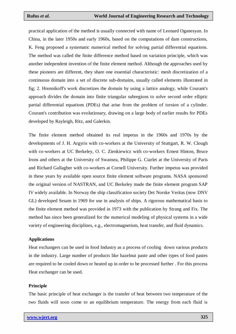
practical application of the method is usually connected with name of Leonard Oganesyan. In
China, in the later 1950s and early 1960s, based on the computations of dam constructions,
K. Feng proposed a systematic numerical method for solving partial differential equations.
The method was called the finite difference method based on variation principle, which was
another independent invention of the finite element method. Although the approaches used by
these pioneers are different, they share one essential characteristic: mesh discretization of a
continuous domain into a set of discrete sub-domains, usually called elements illustrated in
fig; 2. Hrennikoff's work discretizes the domain by using a lattice analogy, while Courant's
approach divides the domain into finite triangular subregions to solve second order elliptic
partial differential equations (PDEs) that arise from the problem of torsion of a cylinder.
Courant's contribution was evolutionary, drawing on a large body of earlier results for PDEs
developed by Rayleigh, Ritz, and Galerkin.
The finite element method obtained its real impetus in the 1960s and 1970s by the
developments of J. H. Argyris with co-workers at the University of Stuttgart, R. W. Clough
with co-workers at UC Berkeley, O. C. Zienkiewicz with co-workers Ernest Hinton, Bruce
Irons and others at the University of Swansea, Philippe G. Ciarlet at the University of Paris
and Richard Gallagher with co-workers at Cornell University. Further impetus was provided
in these years by available open source finite element software programs. NASA sponsored
the original version of NASTRAN, and UC Berkeley made the finite element program SAP
IV widely available. In Norway the ship classification society Det Norske Veritas (now DNV
GL) developed Sesam in 1969 for use in analysis of ships. A rigorous mathematical basis to
the finite element method was provided in 1973 with the publication by Strang and Fix. The
method has since been generalized for the numerical modeling of physical systems in a wide
variety of engineering disciplines, e.g., electromagnetism, heat transfer, and fluid dynamics.
Applications
Heat exchangers can be used in food Industry as a process of cooling down various products
in the industry. Large number of products like hazelnut paste and other types of food pastes
are required to be cooled down or heated up in order to be processed further . For this process
Heat exchanger can be used.
Principle
The basic principle of heat exchanger is the transfer of heat between two temperature of the
two fluids will soon come to an equilibrium temperature. The energy from each fluid is

Rufus et al. World Journal of Engineering Research and Technology
www.wjert.org
326
exchanged and no extra heat is added or removed. Since the heat in the process is not
constant and the heat amount of the fluids is also not constant thus the Heat exchanger must
be designed in a way that it is suited for alluids. Two fluids are brought in close contact with
each other but are prevented from mixing by a physical barrier illustrated in fig; 2 The
temperature of the two fluids will soon come to an equilibrium temperature. The energy from
each fluid is exchanged and no extra heat is added or removed. Since the heat in the process
is not constant and the heat amount of the fluids is also not constant thus the Heat exchanger
must be designed in a way that it is suited for all the cases of heat exchange and the
performance is best suited for all conditions. Also the design should be such that the heat
exchange is at a particular rate required by the process.
Tube Diameter
The most common sizes used are 3/4"od and 1"od Use smallest diameter for greater heat
transfer area with a normal minimum of 3/4"od tube due to cleaning considerations and
vibration.1/2"od tubes can be used on shorter tube lengths say < 4ft. The wall thickness is
defined by the Birmingham wire gage (BWG) illustrated in fig.
Tube Number and Length
Select the number of tubes per tube side pass to give optimum velocity 3-5 ft/s (0.9-1.52 m/s)
for liquids and reasonable gas velocities are 50-100 ft/s (15-30 m/s) If the velocity cannot be
achieved in a single pass consider increasing the number of passes. Tube length is determined
by heat transfer required subject to plant layout and pressure drop constraints. To meet the
design pressure drop constraints may require an increase in the number of tubes and/or a
reduction in tube length. Long tube lengths with few tubes may give rise to shell side
distribution problems
Shell Diameter
The design process is to fit the number of tubes into a suitable shell to achieve the desired
shell side velocity 4ft/s (1.219m/s) subject to pressure drop constraints. Most efficient
conditions for heat transfer is to have the maximum number of tubes possible in the shell to
maximise turbulence. Preferred tube length to shell diameter ratio is in the range 5 to Tubes
have been eliminated to provide entrance area for a nozzle equal to 0.2 times shell diameter
Tube layouts are symmetrical about both the horizontal and vertical axes Distance from tube
od to centre line of pass partition 7.9mm (/16) for shell id <559mm (22in) and 9.5mm (/8) for
larger shells.

Rufus et al. World Journal of Engineering Research and Technology
www.wjert.org
327
Applying Computers to Design
No other idea or device has impacted engineering as computers have. All engineering
disciplines routinely use computer for calculation, analysis, design and simulation .Many of
the individual tasks within the overall design process can be performed using a computer. As
each of these tasks is made more efficient, the efficiency of the overall process increases as
well. The computer is especially well suited to design in four areas, which correspond to the
latter four stages of the general design process. Computers function in the design process
through geometric modeling capabilities, engineering analysis calculations, automated testing
procedures, and automated drafting. Illustrated in fig 1-9
Static Analysis
Determines reaction forces at the joint positions of resting when a constant load is applied
fig4. As long as zero velocity is assumed, static analysis can be performed on mechanisms at
different points of their range of motion. Static analysis allows the designer to determine the
reaction forces on whole mechanical systems as well as interconnection forces transmitted to
their individual joints. criteria set out in the problem definition. These criteria may include
reliability, fatigue, and performance The data extracted from static analysis can be useful in
determining compatibility with the various considerations to be analyzed through stress
analysis methods. Detailed the Region with FOS (factor of safety) value less than 1 in red
Experimental Analysis
Involves fabricating a prototype and subjecting it to various experimental methods. Although
this usually takes place in the later stages of design, CAD systems enable the designer to
make more effective use of experimental data, especially where analytical methods are
thought to be unreliable for the given model. CAD also provides a useful platform for
incorporating experimental results shown in fig 5.
Why Use Simulation Modeling?
We will use the term “simulation platform” to refer to the software environment used to
develop, test and run a simulation experiment. First, let‟s examine what features a simulation
platform needs. Following is a list of the capabilities that must be available:
A way to represent mathematical and logical relationships between variables in the form
of computations and assignment of values, and algorithms that describe how to do a series
of computations.

Rufus et al. World Journal of Engineering Research and Technology
www.wjert.org
328
A way to generate random numbers and use them to sample observations from various
distributions.
A means to repeat a series of computations, thus implementing replications. This list s
minimal. All of these features are necessary for the platform to be used for simulation.
How to Design a Simulation Experiment
A simulation experiment is a test or a series of tests in which meaningful changes are made to
the input variables of a simulation model so that we may observe and identify the reasons for
changes in the performance measures. The number of experiments in a simulation study is
greater than or equal to the number of questions being asked about the model (e.g., Is there a
significant difference between the mean delay in communication, Networks A and B?, Which
network has the least delay Design of a simulation experiment involves answering the
question: what data need to be obtained, in what form, and how much.
Design Analysis of Shel and Tube Heat Exchanger
Fig. 1: Explode Views of Shell and Tube heat exchanger. Fig. 2: Discretization of shell and tube Heat exchanger.

Rufus et al. World Journal of Engineering Research and Technology
www.wjert.org
329
Fig. 3: Material analysis and Constrain. Fig. 3: Wire Frame.
Fig. 4: Material analysis and Constrain.
Fig. 5: Y. Displacement. Fig. 6: Multiply Views.

Rufus et al. World Journal of Engineering Research and Technology
www.wjert.org
330
Fig. 7: Direction of flows. Fig. 8: Sustainability analysis of the shell and
tube Component Environmental Impact.
Fig. 9: Final Drawing and the Major Components of Shell and Tube Heat Exchanger.

Rufus et al. World Journal of Engineering Research and Technology
www.wjert.org
331
Top Ten Components Contributing Most to the Four Areas of Environmental Impact
Environmental Impact (calculated using CML impact assessment methodology)
Carbon Footprint
Material: 180 kg CO2e
Manufacturing: 31 kg CO2e
Use: 0.00 kg CO2e
Transportation: 2.7 kg CO2e
End of Life: 22 kg CO2e
240 kg CO2e
Total Energy Consumed
Material: 2000 MJ
Manufacturing: 310 MJ
Use: 0.00 MJ
Transportation: 34 MJ
End of Life: 16 MJ
2300 MJ
Air Acidification
Material: 0.963 kg SO2e
Manufacturing: 0.442 kg SO2e
Use: 0.00 kg SO2e
Transportation: 0.089 kg SO2e
End of Life: 0.011 kg SO2e
1.5 kg SO2e
Water Eutrophication
Material: 0.571 kg PO4e
Manufacturing: 0.017 kg PO4e
Use: 0.00 kg PO4e
Transportation: 8.4E-3 kg PO4e
End of Life: 0.027 kg PO4e
0.623 kg PO4e
Material Financial Impact
75.40 USD
Comments
Rufus et al. World Journal of Engineering Research and Technology
www.wjert.org
332
Design Process
The ability to create something out of nothing makes design one of the most exciting aspects
of engineering. To be successful, design engineer require abroad set of talents include.
Knowledge creativity, people skill and planning ability Engineers use CAD to create two−
and three−dimensional drawings, such as those for automobile and airplane parts, floor plans,
and maps and machine assembly. While it may be faster for an engineer to create an initial
drawing by hand, it is much more efficient to change and adjust drawings by computer. In the
design stage, drafting and computer graphics techniques are combined to produce models of
different machines. Using a computer to perform the six−step‟art−to−part‟ process: The first
two steps in this process are the use of sketching software to capture the initial design ideas
and to produce accurate engineering drawings. The third step is rendering an accurate image
of what the part will look like Next, engineers use analysis software to ensure that the part is
strong enough shown in fig; 5 Step five is the production of a prototype, or model CAD
began as an electronic drafting board, a replacement of the traditional paper and pencil
drafting method. Over the years it has evolved into a sophisticated surface and solid modeling
tool. Not only can products be represented precisely as solid models, factory shop floors can
also be modeled and simulated in 3D. It is an indispensable tool to modern engineers
illustrated in fig 6.
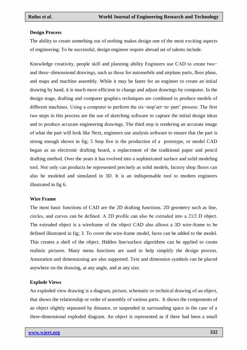
Wire Frame
The most basic functions of CAD are the 2D drafting functions. 2D geometry such as line,
circles, and curves can be defined. A 2D profile can also be extruded into a 21⁄2 D object.
The extruded object is a wireframe of the object CAD also allows a 3D wire-frame to be
defined illustrated in fig; 3. To cover the wire-frame model, faces can be added to the model.
This creates a shell of the object. Hidden line/surface algorithms can be applied to create
realistic pictures. Many menu functions are used to help simplify the design process.
Annotation and dimensioning are also supported. Text and dimension symbols can be placed
anywhere on the drawing, at any angle, and at any size.
Explode Views
An exploded view drawing is a diagram, picture, schematic or technical drawing of an object,
that shows the relationship or order of assembly of various parts. It shows the components of
an object slightly separated by distance, or suspended in surrounding space in the case of a
three-dimensional exploded diagram. An object is represented as if there had been a small

Rufus et al. World Journal of Engineering Research and Technology
www.wjert.org
333
controlled explosion emanating from the middle of the object, causing the object's parts to be
separated an equal distance away from their original locations. The exploded view drawing is
used in parts catalogs, assembly and maintenance manuals and other instructional material.
The projection of an exploded view is usually shown from above and slightly in diagonal
from the left or right side of the drawing. An exploded view drawing is a type of drawing,
that shows the intended assembly of mechanical or other parts. Shown in fig; 1.
Modelling
Modeling is the process of producing a model; a model is a representation of the construction
and working of some system of interest as shown in fig 9. A model is similar to but simpler
than the system it represents. One purpose of a model is to enable the analyst to predict the
effect of changes to the system. On the one hand, a model should be a close approximation to
the real system and incorporate most of its salient features. On the other hand, it should not
be so complex that it is impossible to understand and experiment with it. A good model is a
judicious tradeoff between realism and simplicity. Simulation practitioners recommend
increasing the complexity of a model iteratively. An important issue in modeling is model
validity. Model validation techniques include simulating the model under known input
conditions and comparing model output with system output. Generally, a model intended for
a simulation study is a mathematical model developed with the help of simulation software.
Mathematical model classifications include deterministic (input and output variables are fixed
values) or stochastic (at least one of the input or output variables is probabilistic); static (time
is not taken into account) or dynamic (time-varying interactions among variables are taken
into account). Typically, simulation models are stochastic and dynamic.
Simulation
A simulation of a system is the operation of a model of the system. The model can be
reconfigured and experimented with; usually, this is impossible, too expensive or impractical
to do in the system it represents. The operation of the model can be studied, and hence,
properties concerning the behavior of the actual system or its subsystem can be inferred. In its
broadest sense, simulation is a tool to evaluate the performance of a system, existing or
proposed, under different configurations of interest and over long periods of real time.
Simulation is used before an existing system is altered or a new system built, to reduce the
chances of failure to meet specifications, to eliminate unforeseen bottlenecks, to prevent
under or over-utilization of resources, and to optimize system performance. For instance,

Rufus et al. World Journal of Engineering Research and Technology
www.wjert.org
334
simulation can be used to answer questions like: What is the best design for a new network?
What are the associated resource requirements? How will a telecommunication network
perform when the traffic load increases by 50%? How will new routing algorithm affect its
performance? Which network protocol optimizes network performance? What will be the
impact of a link failure? The subject of this tutorial is discrete event simulation in which the
central assumption is that the system changes instantaneously in response to certain discrete
events. For instance, in an M/M/1 queue - a single server queuing process in which time
between arrivals and service time are exponential - an arrival causes the system to change
instantaneously. On the other hand, continuous simulators, like flight simulators and weather
simulators, attempt to quantify the changes in a system continuously over time in response to
controls. Discrete event simulation is less detailed (coarser in its smallest time unit) than
continuous simulation but it is much simpler to implement, and hence, is used in a wide
variety of situations illustrated in fig 2-5.
Finite Element Analysis
Finite element analysis (FEA) is a computerized analysis method to envisage how a
manufactured product will react to the physical world. The analysis includes bringing the
product in contact with force, heat, vibration, fluid flow and other such physical conditions.
The FEA can predict if the product is likely to break, tear, wear or behave the way it is
manufactured to First developed in 1943 by R. Courant, finite element analysis is a part of the
manufacturing process in order to help predict how an object would react to real-world
conditions when used. FEA also helps solid-state scientists to improve the quality and
function of an object. FEA essentially computes the individual component behavior and sums
it up to predict the overall behavior of the manufactured product. FEA now commonly uses
computers to model the object, which is then stressed and analyzed to obtain desired results.
In the case of a faulty product or undesired result, FEA can help create a new design to meet
the necessary conditions.
A typical finite element analysis on a software system requires the following information
Nodal point spatial locations (geometry) Elements connecting the nodal points, Mass
properties, Boundary conditions or restraints, Loading or forcing function details, Analysis
options.

Rufus et al. World Journal of Engineering Research and Technology
www.wjert.org
335
Procedures
Divide structure into pieces (elements with nodes) (discretization/meshing) Connect
(assemble) the elements at the nodes to form an approximate system of equations for the
whole structure (forming element matrices) Solve the system of equations involving
unknown quantities at the nodes (e.g., displacements).
Calculate desired quantities (e.g., strains and stresses) at selected elements Illustrated in fig 2.
Basic Theory
The way finite element analysis obtains the temperatures, stresses, flows, or other desired
unknown parameters in the finite element model are by minimizing an energy functional. An
energy functional consists of all the energies associated with the particular finite element
model. Based on the law of conservation of energy, the finite element energy functional must
equal zero. The finite element method obtains the correct solution for any finite element
model by minimizing the energy functional. The minimum of the functional is found by
setting the derivative of the with respect to the unknown grid point potential for zero.
Discretization
Meshing Coarse: Faster computation; not concerned about stress concentrations,
singularities, or warping. Not near changes in geometry or displacement constraints or
changes in material including thickness.
Meshing Fine: Best approximation but at the cost of the computation time. Look for
disproportionate stress level changes from node to node or plate to plate and large adjacent
node displacement differences to determine if need to refine the mesh. Nodes should be
defined at locations where changes of geometry or loading occur. Changes in geometry relate
to thickness, material and/or curvature. A simple check, if you can, is to decrease the mesh
size by 50%, re-run analysis, and compare the change of magnitude of stresses and strains. If
there is no significant change, then ok. In most companies, all of this knowledge of mesh size
will be known and might be set a FEA control file illustrated in fig 2.
Sustainability
Simulation technology has been a significant tool for improving manufacturing operations in
the past; but its focus has been on lowering costs, improving productivity and quality, and
reducing time to market for new products. Sustainable manufacturing includes the integration

Rufus et al. World Journal of Engineering Research and Technology
www.wjert.org
336
of processes, decision-making and the environmental concerns of an active industrial system
to achieve economic growth, without destroying precious resources or the environment.
Sustainability applies to the entire life cycle of a product shown in fig: 8 also detailed in
component environment impact. It involves selection of materials, extraction of those
materials, of parts, assembly methods, retailing, product use, recycling, recovery, and
disposal will need to occur if simulation is to be applied successfully to sustainability.
Manufacturers will need to focus on issues that they have not been concerned with before
Design for Environment (DFE)
Is systematic consideration of design performance with respect to environmental, health,
safety, and sustainability objectives over the full product and process life cycle.
Environmentally Sustainable Design
Designers make decisions on the use of resources, modes of consumption and the lifecycles
of products and services. Environmentally sustainable Design (also referred to as „green
design‟ Or „eco-design‟) aims to ensure that products, services and systems are produced and
provided in a way that reduces the use of non-renewable resources and minimizes
environmental impact. It is increasingly important within the fields of architecture, urban
design and planning, and design in general. Some common principles of environmentally
sustainable design are as follows: Low-impact materials: designing for use of non-toxic,
sustainably-produced or recycled materials which require little or no natural resources (such
as energy and water) to transport and process, and whose use does not threaten bio-diversity;
Resource efficiency: designing manufacturing processes, services and products which
consume as little natural resources as possible; Quality and durability: creating longer-lasting
and better-functioning products that last longer, or age in a manner that does not reduce the
value of the product, reducing the impact of producing replacements Reuse, recycling and
renewability: designing products that can composted be reused, recycled or after initial use.
CONCLUSION AND RECOMMENDATION
Heat exchangers find a variety of applications in various bioprocess industries in Food
industry: for production of juices, hazel nut pastes yoghurts and other products, Ethanol
production and Beverage Industry for production of wines, beer, ethanol and vinegar.
Simulation technology has been a significant tool for improving manufacturing operations in
the past; but its focus has been on lowering costs, improving productivity and quality, and
reducing time to market. CAD Has allowed the designer to bypass much of the Manuel
Rufus et al. World Journal of Engineering Research and Technology
www.wjert.org
337
drafting and analysis. Simulation tools enable us to be creative and to quickly test new ideas
that would be much More difficult, time-consuming, and expensive to test in the lab. (Jeffrey
D. Wilson Nasa Glenn Research Center) It also help us reduce cost and time -to-market by
testing our designs on the computer rather than in the field. Many of the individual tasks
within the overall design process can be performed using a computer. Base on this discuss the
following policy are necessary, efforts should be made to adopt and popularize the design-,
FEA, DFM, DFE ETC especially for the benefits of mankind who make up a great
percentage of the Nation„s population. If, the use of machine design adopted, the problem in
agricultural processing Equipment will be minimized and hunger and poverty will be
eradicated , detailed experiment of shell and tube Heat exchanger will be presented in the
future work.
REFERENCES
1. Padmakshi Agarwal, Adhirath Sikand and Shanthi V* Application of Heat Exchangers in
Bioprocess Industry: A Review by International Journal of Pharmacy and Pharmaceutical
Sciences, 2014; ISSN- 0975-1491.
2. Carla S. Fernandesa, Ricardo P. Dias* b,c and João M. Maiad New Plates for Different
Types of Plate Heat Exchangers BY Recent Patents on Mechanical Engineering, 2008; 1:
198-205.
3. https://www.talumis.com/what-is-simulation/.
4. http://www.open.edu/openlearn/science-maths-technology/computing-and-ict/models.
5. Andrew F. Seila Spreadsheet Simulation Proceedings of the Winter Simulation
Conference S. Chick, P. J. Sánchez, D. Ferrin, and D. J. Morrice, eds, 2003.
6. Anu Maria Introduction to Modeling and Simulation Proceeding of the winter simulation
conference ed s. andradottir KJ Healy, D. H Withers and B. L. Nelson, 1997.
7. Padmakshi Agarwal, Adhirath Sikand and Shanthi V* Application of Heat Exchangers in
Bioprocess Industry: A Review published by International Journal of Pharmacy and
Pharmaceutical Sciences ISSN 0975-1491, 2014; 6(1).
8. http://www.me.berkeley.edu/~lwlin/me128/FEMNotes.pdf.
9. Kravanja P, Koenighofer K Canella L m Jungmeier G. Canella L m Jungmeier G, Friedl
A. Perspectives for the production of bioethanol from wood and straw in Austria:
Technical, economic and ecological aspects Technical, economic and ecological aspects
Clean Technol Environ, 2012; 14(3): 411-25.

Rufus et al. World Journal of Engineering Research and Technology
www.wjert.org
338
10. Philipp Kravanja, Ala Modarresi, Anton Friedl Heat Integration of Biochemical ethanol
production from straw-a case study, Applied Energy, 2013; 102: 32-43.
11. Heating and cooling of hazelnut paste in alternate blades scraped surface heat exchangers
Luca D‟ Addio, Claudia Carotenuuto, Francesca Di Natalie, Roberto Nigro, J. of Food
Engineering, 2013; 115(2): 182-189.
12. Julio Cesar Pacio, Carlos Alberto Dorao, A review on heat exchanger thermal hydraulic
models for cryogenic applications, J. of Cryogenics, 2011; 51(7): 366-379.
13. Ozkol, G. Komurgoz Determination of the optimum geometry of the heat exchanger body
via a genetic algorithm, Numerical Heat Transfer Part A: Appl., 2005; 48: 283–296.
14. Sadik Kakaç and Hongtan Liu Heat Exchangers: Selection, Rating and Thermal Design
(2nd ed.). CRC Press. ISBN 0-8493-0902-6, 2002.
15. Saunders, E. A. Heat Exchanges: Selection, Design and Construction. New York:
Longman Scientific and Technical, 1988.
16. Law, A. M., and W. D. Kelton. Simulation Modeling and Analysis, Second Edition,
McGraw-Hill, 1991.
17. Banks, J., J. S. Carson, II, and B. L. Nelson. Discrete-Event System Simulation, Second
Edition Prentice Hall, 1996.
18. Law, A. M., and M. G. Mc Comas. Secrets of Successful Simulation Studies,
Proceedings of the Winter Simulation Conference, ed. J. M., 1991.
19. Charnes, D. M. Morrice, D. T. Brunner, and J. J. Swain, Institute of Electrical and
Electronics Engineers, Piscataway, New Jersey, 21-27.
20. John E. Edwards Design And Rating Shell And Tube Heat Exchangers MNL 032A
Issued 29 August 08, Prepared by J. E. Edwards of P & I Design Ltd, Teesside, UK
www.pidesign.co.uk, 2008.
21. https://www.techopedia.com/definition/19296/finite-element-analysis-fea.
22. https://www.accessengineeringlibrary.com/browse/introduction-to-the-finite-element.
23. https://en.wikipedia.org/wiki/Finite_element_method#Discretization.
24. https://en.wikipedia.org/wiki/Analysis.
25. Daryl L. Logan a first course in the finite element method. Cengage Learning. ISBN 978-
0495668251, 2011.
26. Reddy, J.N. An Introduction to the Finite Element Method (Third ed.). McGraw-Hill.
ISBN 9780071267618, 2006.
27. "Finite Elements Analysis (FEA)". Www.manortool.com. Retrieved, 2017-07-28.

Rufus et al. World Journal of Engineering Research and Technology
www.wjert.org
339
28. Hrennik off, Alexander "Solution of problems of elasticity by the framework method".
Journal of applied mechanics, 1941; 8.4: 169–175.
29. Courant, R. "Variational methods for the solution of problems of equilibrium and
vibrations". Bulletin of the American Mathematical Society, 1943; 49: 1–23.
doi:10.1090/s0002-9904-1943-07818-4.
30. "СПб ЭМИ РАН". emi. nw. ru. Retrieved 17 March. Hinton, Ernest; Irons, Bruce (July
1968). "Least squares smoothing of experimental data using finite elements". Strain,
2018; 4: 24–27. doi:10.1111/j.1475-1305.1968.tb01368.x.
31. "SAP-IV Software and Manuals". NISEE e-Library, The Earthquake Engineering Online
Archive.
32. Gard Paulsen; Håkon with Andersen; John Petter Collett; Iver Tangen Stensrud. Building
Trust, The history of DNV 1864-2014. Lysaker, Norway: Dinamo Forlag A/S, 2014; 121:
436. ISBN 978-82-8071-256-1.
33. Anastasovski, L. Markosvska, V. Mesko, Process integration in bioprocess industry waste
heat recovery in yeast and ethyl alcohol plant, Journal Energy, 2010; 35: 704-717.
34. https://en.wikipedia.org/wiki/Exploded-view_drawing.
35. United States Patent and Trademark Office General Information Concerning Patents §
1.84 Standards for drawings (Revised January). Accessed 13 Feb 2009, 2005.
36. Rufus Ogbuka Chime et al Design, Modeling, Application and Analysis of Bevel Gears.
Int. Journal of Engineering Research and Applications www.ijera.com ISSN: 2248-9622,
April 2016; 6(4): (Part - 3) 44-52.


