
MAHARASHTRA STATE BOARD OF TECHNICAL EDUCATION (Autonomous)
(ISO/IEC - 27001 - 2005 Certified)
Page1
MODEL ANSWER WINTER– 17 EXAMINATION
Subject Title: Industrial Measurements Subject Code: Important Instructions to examiners:
1) The answers should be examined by key words and not as word-to-word as given in the model answer scheme. 2) The model answer and the answer written by candidate may vary but the examiner may try to assess the
understanding level of the candidate. 3) The language errors such as grammatical, spelling errors should not be given more Importance (Not applicable for
subject English and Communication Skills. 4) While assessing figures, examiner may give credit for principal components indicated in the figure. The figures
drawn by candidate and model answer may vary. The examiner may give credit for any equivalent figure drawn. 5) Credits may be given step wise for numerical problems. In some cases, the assumed constant values may vary and
there may be some difference in the candidate’s answers and model answer.
6) In case of some questions credit may be given by judgement on part of examiner of relevant answer based on candidate’s understanding.
7) For programming language papers, credit may be given to any other program based on equivalent concept.
Q. No. Sub
Q.N.
Answer Marking
Scheme
Q.1 (A) Attempt any SIX- 12-Total
Marks
(a) List the four different units of pressure. 2M
Ans: Different units of pressure.
1) Measured in pascal(Pa).
2) Measured in pounds per square inch(psi)
3) Measured in kilogram per square of centimeter (Kg/cm2 ).
4) Measured in newton per square meter (N/m2 ).
5) Measured in terms of liquid columns. mmHg or mmWc
½ M each
Any 4
(b) List any two piezoelectric materials. 2M
Ans: 1) Natural Crystals- Quartz crystal, Rochelle salt
2) Synthetic Crystal-Barium Titanium
1M each
(c) Draw the different shapes of thermistors. 2M
17434

MAHARASHTRA STATE BOARD OF TECHNICAL EDUCATION (Autonomous)
(ISO/IEC - 27001 - 2005 Certified)
Page2
Ans:
1M each
(d) Define laminar and turbulent flow. 2M
Ans: Laminar Flow: When all the molecules of flow are parallel to each other, it is
called laminar flow.
Turbulent flow: When the flow molecules are scattered without any fixed
pattern, it is called Turbulent Flow.
1M each
(e) Define humidity. State its units. 2M
Ans: Humidity: Amount of water vapour present in the atmosphere.
Units:
1) gm/ml3
2) grams of water vapour per cubic meter volume of air.
1M-
Definition
1M- Units
(f) Classify the temperature measuring transducers. 2M
Ans:
2M

MAHARASHTRA STATE BOARD OF TECHNICAL EDUCATION (Autonomous)
(ISO/IEC - 27001 - 2005 Certified)
Page3
OR
1.Expansion thermometers:
Bimetallic thermometers
Bimetal Helix Thermometer
Spiral Bimetallic thermometers
2. Filled system thermometers:
Liquid filled thermometers
Gas filled thermometers
Vapour pressure thermometers
3. Electrical Temperature Instruments:
RTD
Thermistors
Thermocouples
4. Pyrometers:
Radiation Pyrometers
Infrared Pyrometers
Optical Pyrometers
½ M each
(g) State classification of flow meters. 2M
Ans:
2M
(h) State two advantages of electrical transducers. 2M
Ans: Advantages of electrical transducers-(Any Two)
1) The electrical systems can be controlled with a very small level of power.
2) The electrical output can be easily used, transmitted and processed for the
process of measurement.
3) The output can be indicated and recorded remotely from the sensing element.
4) Friction effect is minimized.
1M each
(Any other
relevant
answer)
MAHARASHTRA STATE BOARD OF TECHNICAL EDUCATION (Autonomous)
(ISO/IEC - 27001 - 2005 Certified)
Page4
B) Attempt any TWO: 8M 8 M
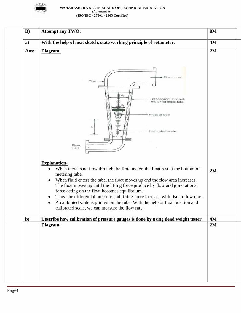
a) With the help of neat sketch, state working principle of rotameter. 4M
Ans:
Diagram-
Explanation-
When there is no flow through the Rota meter, the float rest at the bottom of
metering tube.
When fluid enters the tube, the float moves up and the flow area increases.
The float moves up until the lifting force produce by flow and gravitational
force acting on the float becomes equilibrium.
Thus, the differential pressure and lifting force increase with rise in flow rate.
A calibrated scale is printed on the tube. With the help of float position and
calibrated scale, we can measure the flow rate.
2M
2M
b) Describe how calibration of pressure gauges is done by using dead weight tester. 4M
Diagram-
2M

MAHARASHTRA STATE BOARD OF TECHNICAL EDUCATION (Autonomous)
(ISO/IEC - 27001 - 2005 Certified)
Page5
Explanation-
The handle is fully drawn out and the oil is allowed to enter in the cylinder (i.e.
gauge and piston).
A known accurate weight is placed on the platform. The area of piston is also
known; hence we can calculate the pressure. Now the handle is turn to press in
clockwise direction so that the pressure will buildup on the gauge side as well as
platform side.
Increase the pressure by rotating the handle clockwise until enough pressure is
developed inside the cylinder and lifts the platform with weights placed on it and it
floats freely within the limit stops.
Repeat the same procedure for different weights. In the same way most of the
pressure gauge are calibrated against dead weight testers.
An error in dead weight tester is less than 0.1% in order to reduce the friction
between the piston and cylinder, the piston is gradually rotated while a reading being
taken.
2M
c) What is need of level measurement? Give classification of level measurement
methods with two examples of each.
4M
Ans: In almost all industries, vast quantities of liquid such as water solvents, chemicals etc.
are used in number of processes. It is widely employed to monitor as well as measure
quantitatively the liquid content in the tanks, containers and vessels et . Liquid level
affects both pressure and rate of flow in and out of the container and therefore its
measurement becomes important in a variety of processes encountered in modern
manufacturing plants.
Classification of Liquid Level Measurement:
Direct method 1. Hook type
2. Sight glass type
3. Float type
4. Dip stick
Indirect method 1. Hydrostatic pressure type
2. Electrical type:
1M- Need
3M

MAHARASHTRA STATE BOARD OF TECHNICAL EDUCATION (Autonomous)
(ISO/IEC - 27001 - 2005 Certified)
Page6
a) Capacitance level indicator
b) Radiation level detector
c) Ultrasonic level gauge
3. Radar type
Q 2 Attempt any FOUR: 16M
(a) State working principle of 'C' type bourdon tube with neat diagram. 4M
Ans: Diagram-
Explanation-
C type bourdon tube is made up of an elliptically flattened tube bent in such a way
as to produce the C shape as shown in the fig. One end free end of this tube is closed
or sealed and the other end (fixed end) opened for the pressure to enter. The free end
connected to the pointer with the help of geared sector and pinion. Calibrated scale
and pointer is provided to indicate the pressure.
The cross section view of C type bourdon tube under normal condition and
pressurized condition is as shown in figure.
The pressure which is to be measured is applied to the bourdon tube through open
end. When this pressure enters the tube, the tube tends to straighten out proportional
to applied pressure.
This causes the movement of the free end and the displacement of this end is given
to the pointer through mechanical linkage i.e. geared sector and pinion
The pointer moves on the calibrated scale in terms of pressure. The relationship
between the displacement of the free end and the applied pressure is nonlinear.
2M
2M
(b) Describe working of venture meter with neat sketch. 4M

MAHARASHTRA STATE BOARD OF TECHNICAL EDUCATION (Autonomous)
(ISO/IEC - 27001 - 2005 Certified)
Page7
Ans: Diagram-
Explanation- It is a primary element of differential pressure Flow meters.
1) It consists of a straight inlet section, a converging conical inlet section, a
cylindrical throat and diverging recovery cone.
2) Straight inlet section has same diameter as pipe. In converging conical inlet section,
the cross-section of stream decreases & velocity increases.
3) In cylindrical throat, flow velocity will be maximum & static pressure will be
minimum
4) In diverging recovery cone flow velocity decreases taps are located at.
5) The pressure taps are located at straight edge section and at cylindrical throat where
pressure is minimum thus the maximum Pressure Gauges across this point.
6) As it have no sharp edges or warner and does not project into fluid stream. It can
be used to handle fluids with solid, slurries, etc.
7) The cross sectional area of fluid does not increase or decreases. Abruptly, so
permanent pressure loss or energy loss is very low as compared to orifice plate.
8) Venture tube are usually made up of cast iron or steel and built up in several forms
such as.
a) Long from or classic venture tube.
b) Short from where outlet cone is shortened.
c) Eccentric from to minimize the buildup of heavy materials.
d) Rectangular from which is used in air-duct work.
2M
2M
(c) Describe working principle of optical pyrometer with neat diagram. 4M
Ans: Diagram-
2M

MAHARASHTRA STATE BOARD OF TECHNICAL EDUCATION (Autonomous)
(ISO/IEC - 27001 - 2005 Certified)
Page8
Explanation-
The working principle of optical pyrometer state that the brightness of light of a given
color emitted by a hot source, gives an indication of temperature.
Working:
It consists of a tube, one end of this tube has objective lens and other end has a
sighting eye piece to observe the filament.
The filament is viewed through filter and eye piece. The lens side of tube is
projected towards the hot body whose temperature is to be measured.
An image of radiating source is produced by a lens and made to coincide with
the filament of an electric lamp.
The current through the lamp filament is made variable so that lamp intensity
can be adjusted.
The current through filament is adjusted until the filament and the image are of
equal brightness.
During the operation of optical pyrometer following conditions occurs.
1. When the temperature of the filament is higher than that required for equal
brightness then the filament is too bright as shown in the figure.
2. When the temperature of filament is lower, the filament becomes too dark as
shown in figure. When the brightness of image produced by the source and brightness
produced by the filament are equal, the outline of the filament disappear.
2M
(d) Write two advantages and applications of ultrasonic level measurement. 4M
Ans: Advantages of Ultrasonic Method of Level Measurements:
1) Ultrasonic gauge needs to physical contact with the liquid. 2M

MAHARASHTRA STATE BOARD OF TECHNICAL EDUCATION (Autonomous)
(ISO/IEC - 27001 - 2005 Certified)
Page9
2) It is a non-disturbance technique.
3) Used for both solid and liquid level measurement.
4) They have no moving parts.
Applications of Ultrasonic Method of Level Measurements:
1) Ultrasonic level measuring device is used for both continuous and point
measurement.
2) The point measuring ultrasonic detectors are used for measurement of gas/liquid,
liquid/liquid or gas/solid interface.
3) It is used for level measurement of hazardous liquids and solids.
2M
(e) Draw block diagram of instrumentation system. Explain function of each block. 4M
Ans: Diagram-
OR
Explanation- Functions of each block: 1) Primary sensing element: This first receives energy from the measured medium
and produces an output depending on measured quantity.
2) Variable conversion element: Converts the output signal of the primary sensing
element into a more suitable variable or condition useful to the function of the
instrument.
3) Variable manipulation element: Manipulates the signal represented by some
2M
2M

MAHARASHTRA STATE BOARD OF TECHNICAL EDUCATION (Autonomous)
(ISO/IEC - 27001 - 2005 Certified)
Page10
physical variable, to perform the intended task of an instrument. In the
manipulation process, the physical nature of the variable is preserved.
4) A data transmission unit: Transmits the data from one element to the other.
5) A data presentation element: Performs the translation function, such as the
simple indication of a pointer moving a scale or the recording of a pen moving
over chart.
(f) Describe how humidity is measured by using hair type hygrometer. 4M
Ans: Diagram-
Explanation:
It consists of bunch of human hair which increases mechanical strength of the
instrument, arm with pivot joints and points scale assembly.
The element is maintained at slight tension by a spring. The hair strands are
generally arranged parallel to each other with sufficient space between them for
giving free access to the air sample whose humidity is to be measured.
The indicator scale is directly calibrated to give a direct indication of humidity. The
pointer or recording pen is operated through mechanical linkage.
As the relative humidity surrounding to that of hygrometer increases, length of hair
strands increases, which move the pointer on the calibrated scale for maximum value.
2M
2M
Q. 3 Attempt any FOUR: 16M
a) Give two examples of each of the following:
(i) Active transducer(ii) Digital transducer
(iii) Analog transducer(iv) Electrical transducer
4M
Ans: i) Active Transducer -1)Piezo electric transducer 2) Thermocouple 3)Rotary
encoder [any two 1M]
ii) Digital Transducer-1)Optical encoder,2)Digital temperature sensor 3)digital
accelerometer[any other transduce]
iii) Analog Transducer: 1)LVDT 2) thermister 3)thermocouple 4) RTD [Any
two 1M, any other can be given mark]
iv) Electrical Transducer:1) resistive 2) capacitive 3)inductive[Any two 1 M,
any other can be given mark]
1M each for
any two
examples

MAHARASHTRA STATE BOARD OF TECHNICAL EDUCATION (Autonomous)
(ISO/IEC - 27001 - 2005 Certified)
Page11
b) List different elastic pressure transducers and draw constructional details of
anyone.
4M
Ans: The commonly used elastic pressure transducers are :
1)Bourdon Tube: 1)C-Type 2)Spiral 3)Twisted 4)Helical
2)Bellows
3)Diaphragms
4) Capsule
OR Bellows
OR
1M for list
And 3M for
any
constructio
nal detail

MAHARASHTRA STATE BOARD OF TECHNICAL EDUCATION (Autonomous)
(ISO/IEC - 27001 - 2005 Certified)
Page12
OR
OR

MAHARASHTRA STATE BOARD OF TECHNICAL EDUCATION (Autonomous)
(ISO/IEC - 27001 - 2005 Certified)
Page13
OR Capsule
OR
OR

MAHARASHTRA STATE BOARD OF TECHNICAL EDUCATION (Autonomous)
(ISO/IEC - 27001 - 2005 Certified)
Page14
c) With neat diagram, explain working of capacitance level measurement. 4M
Ans: Diagram-
2M
2M
d) Compare between RTD and thermistor with respect to:
(i) Size (ii) Cost
(iii) Material of construction (iv) Temperature range
4M
Ans:
Sr Parameter RTD Thermister
1 size Large Small
2 Cost More Less
3 Material Teen, Nickel, Copper,
Platinum
Manganese, Copper, Iron,
Cobalt
4 Temperature
Range
-200oC to 650
oC -150
oC to 300
oC
1M for each
Parameter
e) With the help of suitable diagram, explain how humidity is measured with dry 4M

MAHARASHTRA STATE BOARD OF TECHNICAL EDUCATION (Autonomous)
(ISO/IEC - 27001 - 2005 Certified)
Page15
and wet bulb thermometer.
Ans: Diagram-
Explanation:- 1. A psychrometer, or wet-and-dry-bulb thermometer, consists of two thermometers,
one that is dry and one that is kept moist with distilled water on a sock or wick. The
two thermometers are thus called the dry-bulb and the wet-bulb. At temperatures
above the freezing point of water, evaporation of water from the wick lowers the
temperature, so that the wet-bulb thermometer usually shows a lower temperature
than that of the dry-bulb thermometer. When the air temperature is below freezing,
however, the wet-bulb is covered with a thin coating of ice and may be warmer than
the dry bulb.
2 .Relative humidity is computed from the ambient temperature as shown by the dry-
bulb thermometer and the difference in temperatures as shown by the wet-bulb and
dry-bulb thermometers. Psychrometers are commonly used in meteorology, and in the
HVAC industry for proper refrigerant charging of residential and commercial air
conditioning systems.
2M
2M
f) Convert 200°F (Fahrenheit) into Celsius, Kelvin, Reaumur, Rankine scale. 4M
Ans: 1) 0C = 5/9 (0F – 32) =5/9(200-32)=93.33
2) 0R =
0F + 459.7 =200+459.7=659.7
oR
3) K = 0C + 273.15 =93.33+273=366.33oK 4) Re=(oF-32)/2.25)=378ORe
1 M for
each scale
Q. 4 Attempt any FOUR: 16M
MAHARASHTRA STATE BOARD OF TECHNICAL EDUCATION (Autonomous)
(ISO/IEC - 27001 - 2005 Certified)
Page16
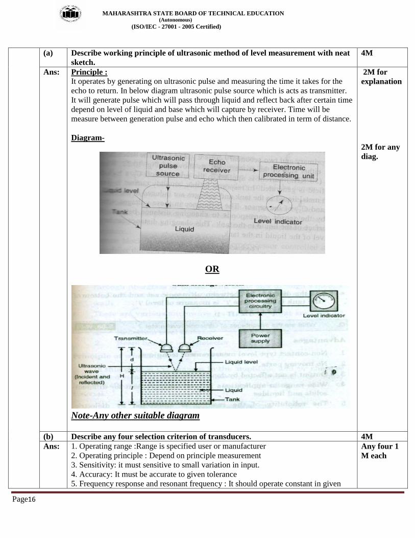
(a) Describe working principle of ultrasonic method of level measurement with neat
sketch.
4M
Ans: Principle : It operates by generating on ultrasonic pulse and measuring the time it takes for the
echo to return. In below diagram ultrasonic pulse source which is acts as transmitter.
It will generate pulse which will pass through liquid and reflect back after certain time
depend on level of liquid and base which will capture by receiver. Time will be
measure between generation pulse and echo which then calibrated in term of distance.
Diagram-
OR
Note-Any other suitable diagram
2M for
explanation
2M for any
diag.
(b) Describe any four selection criterion of transducers. 4M
Ans: 1. Operating range :Range is specified user or manufacturer
2. Operating principle : Depend on principle measurement
3. Sensitivity: it must sensitive to small variation in input.
4. Accuracy: It must be accurate to given tolerance
5. Frequency response and resonant frequency : It should operate constant in given
Any four 1
M each

MAHARASHTRA STATE BOARD OF TECHNICAL EDUCATION (Autonomous)
(ISO/IEC - 27001 - 2005 Certified)
Page17
band width
6. Errors : Minimum
7. Environmental compatibility: It should compatible to given enviroment
8. Usage and ruggedness.
9. Electrical aspect.
10. Stability and Reliability
11. Loading effect
12. Static characteristics
13. General selection criteria
(c) Describe with neat diagram, how temperature is measured by Gas filled
thermometer.
4M
Ans: Diagram-
Explanation:- If volume of a gas is maintained at constant and If a certain volume of inert gas is
enclosed in a bulb, capillary and bourdon tube, the most of the gas in the bulb, then
the pressure increases with increase in temperature and that pressure is indicated by
the bourdon tube may be calibrated in terms of the temperature of the bulb
In other words Working of Gas thermometer is depend upon ideal gas law which state that the
volume of the gas increases with increase in temperature if pressure maintained
constant.
Name of the gases used in Gas filled thermometers. 1. Nitrogen
2. Helium
3. Inert Gas
2M
2M
(d) Draw the construction and explain the working of photoelectric pick-up type
speed measuring transducer.
4M
Ans: Diagram-
2M

MAHARASHTRA STATE BOARD OF TECHNICAL EDUCATION (Autonomous)
(ISO/IEC - 27001 - 2005 Certified)
Page18
OR
Working:- Photo electric pick-up or tachometer is noncontact type device which is used to
measure speed in rpm. It consists of a source light which directs the light beam
towards rotating object. A reflecting mark is affixed to the rotating object. The
photosensor is focused on the area toward the mark. When the object rotates, it
modulates light by reflecting mark, producing a tray of pulses, whose frequency is
proportional to the speed. The number of pulses counts the number of revolutions of
object. The output of photosensor is amplified. The counter is used to count the
number of pulses. A display device is used to read out the output. It may be CRO or
seven segment display or analog meter. The external light may produce error if simple
LED and photosensor is used. Therefore to avoid this, IR (Infra-Red), LED and
photosensor is used. The frequency at which the pulses are produced depends on the
number of holes in the disc and its speed of rotation. Hence the speed is given by
N= f/Hs
where
N=speed
f=frequency
Hs=holes on the disc
2M
(e) State Seeback effect and Peltier effect. Write material used in different
thermocouples.
4M
Ans: Seeback effect:- 1M
Seeback effect states that whenever two dissimilar metals are connected together to
form two junctions out of which, one junction is subjected to high temperature and
2M for any
two type
and

MAHARASHTRA STATE BOARD OF TECHNICAL EDUCATION (Autonomous)
(ISO/IEC - 27001 - 2005 Certified)
Page19
another is subjected to low temperature then e.m.f is induced proportional to the
temperature difference between two junctions.
Peltier effect:- 1M
Peltier effect states that for two dissimilar metals closed loop, if current forced to flow
through the closed loop then one junction will be heated and other will become cool.
List of thermocouple-
SR TYPE Material
1 T Copper/constantan
E Chromel/ constantan
J iron/ constantan
K Chromel/alumel
R Platinum/platinum/13%Rhodium
S Platinum/platinum/10%Rhodium
B Platinum6%/platinum/30%Rhodium
G Tungsten/Tungesten/Rhodium26%
C Tungsten 5%Rhodium/Tungesten/Rhodium25%
material
1M for
(seebeck
and peltier
effect each)
(f) Sketch constructional diagram of inclined tube manometer. State its advantages
and disadvantages.
4M
Ans: Diagram-
Advantages:
1) High sensitivity and accuracy
2) Used to measure small pressure difference
Disadvantage:
1)Large and bulky
2) No over range protection
3)Need of leveling
2M
1M
1M

MAHARASHTRA STATE BOARD OF TECHNICAL EDUCATION (Autonomous)
(ISO/IEC - 27001 - 2005 Certified)
Page20
[Note-Any other relevant advantage and disadvantage can be consider
]
Q.5 Attempt any FOUR: 16M
a) Explain working principle of Doppler type ultrasonic flow meter. Give its two
advantages and disadvantages.
4M
Ans: Diagram:
Working Principal: In Doppler flow meter an ultrasonic wave is projected at an angle through
the pipe wall into the liquid by a transmitting crystal in a transducer mounted outside the pipe.
Part of the ultrasonic wave is reflected by bubbles or particles in the liquid and
is returned through the pipe wall to a receiving crystal. Since the reflector (bubbles) are travelling at the fluid velocity the frequency of
the reflected wave is shifted according to the Doppler principal. The velocity of the fluid is given.
Advantages:
It has no moving parts.
Its velocity (Output relationship is linear) Excellent dynamic response.
Disadvantages:
Complex circuit
1M
2M
1M

MAHARASHTRA STATE BOARD OF TECHNICAL EDUCATION (Autonomous)
(ISO/IEC - 27001 - 2005 Certified)
Page21
Relative high cost
b) State comparison between PTC and NTC. 4M
Ans:
Sr NO. PTC NTC
1 It is positive temperature coefficient
It is negative temperature coefficient
2 As temperature increases resistance also increases Rα T
As temperature increases resistance also decreases Rα 1/T
3 PTC manufactured from barium titanate, titanium oxide, and powdered
NTC composed of metal oxides such as manganese, nickel, cobalt, copper, iron and uranium.
4
Each point
1M
c) Is piezoelectric transducer active or passive? Give reason. Also state the principle
of operation of piezoelectric transducer.
4M
Ans: Diagram:
It is passive transducer
Working principle: When force or pressure is applied to the piezoelectric material like quartz crystal or
barium titanate, then an e.m.f. is generated across the material or vice versa.
The piezoelectric element used for converting mechanical movement into electrical
signals. The mechanical deformation generates a charges and this charges appears as a
voltage across the electrodes.
1M
3M

MAHARASHTRA STATE BOARD OF TECHNICAL EDUCATION (Autonomous)
(ISO/IEC - 27001 - 2005 Certified)
Page22
The voltage is given by ,
V = Q / C
Where V = e.m.f across electrode
Q = Charges
C = capacitance
d) Draw a neat setup diagram to measure level of liquid in a tank using a float and
potentiometer. Also identify the primary sensor and secondary transducer in this
setup.
4M
Ans: Float type liquid level indicator-
Diagram:
Fig 1
Linear potentiometer liquid level gauge.
Diagram:
Fig 2
As shown in fig 1 and fig 2 float acts as primary transducer that convert liquid level
into displacement. This displacement is sensed by secondary transducer such as
resistive type i.e. angular or linear potentiometer.
The resistance of POT is directly proportional to the liquid level in the tank.
2M
2M
e) Compare contact type and non-contact type speed measurement methods. 4M

MAHARASHTRA STATE BOARD OF TECHNICAL EDUCATION (Autonomous)
(ISO/IEC - 27001 - 2005 Certified)
Page23
Ans: Sr.
No
Contact type speed measurement Non-contact type speed
measurement
1 Physical contact is present between meter and shift
No physical contact between meter and rotating shaft.
2 As output is electrical signal to indicate reading.
As the output are digital pulses,no need of A/D converter.
3 Due to contact with rotating parts maintenance is high
As there is no contact structure maintenance free
4 e.g. A.C> Tachometer, D.C.
Tachometer e.g. Magnetic picup meter,
Each point
1M
f) Define pressure. Give the detailed classification of pressure measuring devices. 4M
Ans: Define: Pressure is defined as the amount of force applied to a surface or distributed over it and is measured as force per unit area. Classification of Pressure measuring device
1) Non elastic Pressure transducer/manometer U Tube manometer
Well type
Inclined type
2) Elastic Pressure Transducer/Mechanical
Bourdon tube
Bellows
Diaphragms
3) Electronics Pressure Transducer
Bourdon tube with LVDT
Diaphragms with Strain Gauge(Resistive)
Capacitive, Piezoelectric
1M
3M
Q.6 Attempt any FOUR: 16M
a) Describe the construction, working of an inductive transducer used as a
displacement transducer.
4M
Ans: Diagram:
1M

MAHARASHTRA STATE BOARD OF TECHNICAL EDUCATION (Autonomous)
(ISO/IEC - 27001 - 2005 Certified)
Page24
Explaintion: LVDT is the example of inductive transducer, in LVDT any physical displacement of the core cause the voltage of any secondary winding to increase while simultaneously reducing the voltage in the other secondary winding. The difference of the two voltages appears across the output terminal of the transducer and gives a measurement of the physical position of the core.
Construction of LVDT:
A differential transducer consists of a primary winding and two secondary
winding.
The windings are arranged concentrically and next to each other.
They are wound over a narrow bobbin which is usually of a non- magnetic and
insulating material. A core in the shape of road is attached to the transducer sensing a shaft.
An AC source is applied across the primary winding and core varies the coupling
between it and two
secondary windings. .:E0=E1-E2
1M
2M
b) How strain gauge is used for pressure measurement? Explain. 4M
Ans: Diagram:
2M

MAHARASHTRA STATE BOARD OF TECHNICAL EDUCATION (Autonomous)
(ISO/IEC - 27001 - 2005 Certified)
Page25
Working Principle: 1) Strain gauge is a passive type resistance pressure transducer whose electrical
resistance changes when it is stretched or compressed. It can be attached to a
pressure sensing diaphragm as shown in fig a.
2) When diaphragm flexes due to the process pressure applied on it the strain gauge
stretches or compresses due to this its resistance changes. 3) As soon as the pressure is applied the strain gauge stretches or compresses
accordingly and the bridge circuit in fig( b) is unbalanced due to the change in resistance of the strain gauges
4) Thus a current flows in the galvanometer ,Which is measured by the deflection of the galvanometer, this change in output voltage may be calibrated for the pressure change.
2M
c) Compare orifice plate and venture tube with reference to:
(i) Working principle (ii) Construction
(iii) Maintenance cost (iv) Use
4M
Ans: Parameter Orifice plate Venture tube
Working principle It is the variable area flow
meter in which differential
pressure is developed by using
orifice plate by inserting it in
the path of fluid flow.
Venturi tube operates on
the principle that when
the restriction is placed in
the path of flow, it
produces differential
pressure across the
restriction which is
proportional to the flow
rate
Construction
Maintenance cost high low
Use Low flow measurement High flow measurement
Each
parameter
1M
d) Describe the working of radiation type level measurement. List two
advantages of it.
4M
Ans: Diagram: 1M

MAHARASHTRA STATE BOARD OF TECHNICAL EDUCATION (Autonomous)
(ISO/IEC - 27001 - 2005 Certified)
Page26
Radiation level measurement is non-contact type liquid level measurement technique. Radiation detectors are used where other electrical methods would not survive. Construction and working:
It consists of gamma ray source holder on one side of the tank and a gamma
detector on the other side of the tank.
The gamma rays from source are directed towards the detector in a thin band of
radiation.
When gamma rays penetrate the thick wall of the tank, its energy level afterwards
is greatly reduce
The radiation received at the gamma detector is inversely proportional to the
thickness of the walls and the medium between the radiation source and detector.
The amount of radiation received is inversely proportional to the amount of liquid
between the radiation source and detector. The difference in the amount radiation
received by detector, corresponds to the liquid level in the tank.
Thus, when liquid level rises, the amount of radiation received is reduced and vice
versa.
Advantage:
1) It is used for higher temperature measurement.
2) It is used for the non -contact type method.
2M
1M
e) Explain working principle of bimetallic thermometer. 4M
Ans: Diagram:
1M

MAHARASHTRA STATE BOARD OF TECHNICAL EDUCATION (Autonomous)
(ISO/IEC - 27001 - 2005 Certified)
Page27
1) All metals expand or contracts with change in temperature.
2) The temperature co- efficient of expansion is not same for all metals therefore
their rate of expansion or contraction is not same. The difference in thermal
expansion rate produces deflections proportional to the change in temperature.
It consists of bimetallic strip usually in the form of a cantilever beam, which is
prepared from two thin strips of different metals having different coefficient of
thermal expansion
Working Principle:
The bonding of two strips is done by welding such that they can not move relative to each other.
Brass is used as a high expansion metal and Invar (alloy of iron nickel) is used as low expansion metal.
As the temperature applied to the strip increases, there is deflection of the free end of the strip. The length of metal will change according to the individual expansion rate.
As one end of bimetallic strip is fixed, the strip will bends at free end towards the side that to low coefficient of thermal expansion metal.
The deflection of the free end is directly proportional to the square of the length of the
metal strip, as well as to the total change in temperature, and inversely proportional to
the thickness of the metal
Pointer is attached to the free end to indicate the temperature.
3M
f) Compare between U tube and well type manometers. (any four points) 4M
Ans: Sr No U tube manometer Well type manometer
1 U shape tube Well shape with small
capillary
2 It has two limb It has only one limb
3 P2- P1= d (1+A1/A2)H P2=ρh
4 U tube manometer is for differential
pressure measurment
Direct pressure
measurement
Each point
1M

MAHARASHTRA STATE BOARD OF TECHNICAL EDUCATION (Autonomous)
(ISO/IEC - 27001 - 2005 Certified)
Page28


