USER MANUAL
Thermal Imager IRThermometerMODEL IRC130
Table of contents
1 Introduction........................................................................12 Safety ................................................................................2
2.1 Safety Warnings and Cautions.......................................23 Description.........................................................................3
3.1 Product Description.....................................................33.2 Control Button Descriptions ..........................................43.3 Display Description .....................................................4
4 Operation ...........................................................................64.1 Powering the IRC130...................................................64.2 IR Camera and Thermometer ........................................64.3 High Temperature Switch .............................................74.4 Visible Spectrum Camera .............................................84.5 Capture, View, Transfer, Send, and Delete Camera
Images.....................................................................85 Programming Menu System .................................................9
5.1 Menu System Basics...................................................95.2 Main Menu................................................................95.3 SETTINGS Sub-Menu ............................................... 11
6 Field Firmware Updates ..................................................... 166.1 System Firmware Update ........................................... 16
7 Maintenance..................................................................... 177.1 Cleaning................................................................. 177.2 Battery Considerations and Service.............................. 177.3 Disposal of Electronic Waste....................................... 177.4 Reset the IRC130 ..................................................... 17
8 Specifications................................................................... 188.1 Imaging and Optical Specifications ............................... 188.2 Detector Specifications .............................................. 188.3 Image Presentation Specifications................................ 188.4 Measurement Specifications ....................................... 198.5 Measurement Analysis Specifications ........................... 198.6 Configuration Specifications........................................ 198.7 Image Storage Specifications ...................................... 208.8 Digital Camera ......................................................... 208.9 Flashlight Specifications............................................. 208.10 Laser Pointer Specifications........................................ 20
#NAS100031; r. AD/63425/63425; en-US ii
Table of contents
8.11 Data Interface Specifications....................................... 218.12 Rechargeable Battery Specifications ............................ 218.13 Environmental Specifications ...................................... 218.14 Physical Specifications .............................................. 228.15 Included Equipment .................................................. 22
9 Warranty and Customer Support ......................................... 239.1 Two-Year Warranty .................................................... 239.2 Repair and Calibration Services................................... 239.3 Customer Support .................................................... 23
#NAS100031; r. AD/63425/63425; en-US iii

Introduction1
The Extech IRC130 Thermal Imager IR Thermometer combines non-contacttemperature measurement and thermal imaging into one troubleshooting toolto help you quickly find the source of heat-related problems and to spot poten-tial faults when performing maintenance and repair.
Features
• 80 x 60 pixel true thermal imager (Lepton® microbolometer with integratedshutter)
• Visible spectrum 2M pixel digital camera• Adjustable MSX® (Multi-Spectral Dynamic Imaging) adds key details from
the visible spectrum to the IR image for improved diagnostics• Easy-to-read 320 x 240 2.4” TFTcolor LCD display• Wide temperature range -4 ~ 1202℉ (–20 ~ 650℃)• High temperature switch for measurements > 752℉ (400℃)• Intuitive programming menu system in over 21 languages• 3 presets and 1 custom emissivity setting• LED Flashlight• Laser pointer and cross-hair display for easy targeting• 4 GB internal image capture memory• USB–C connectivity for image transfer and charging• IP54 enclosure protects from dirt, dust, and oil• Rechargeable battery with adjustable auto power off (APO) timer• Accessory mounting for tripods and other accessories
#NAS100031; r. AD/63425/63425; en-US 1
Safety2
2.1 Safety Warnings and Cautions
WARNING
⚠ This symbol, adjacent to another symbol indicates the user must refer to the manual forfurther information.
WARNING
The instrument’s IP54 rating is only in affect when the top flap (covering the USB-C jack) iscompletely sealed. Do not operate the instrument with the flap open, except for chargingand PC interface.
CAUTION
Use of controls or adjustments or performance of procedures other than those specifiedherein may result in hazardous radiation exposure.
CAUTION
Use extreme caution when the Laser pointer is on.
CAUTION
Do not point the Laser beam toward anyone's eye or allow the beam to strike the eye froma reflective surface.
CAUTION
Do not use the Laser near explosive gases or in other potentially explosive areas.
CAUTION
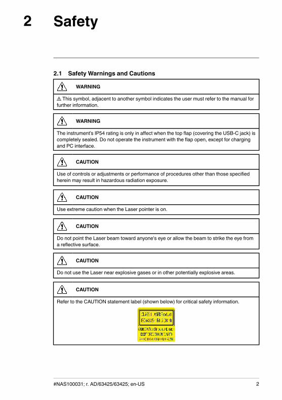
Refer to the CAUTION statement label (shown below) for critical safety information.
#NAS100031; r. AD/63425/63425; en-US 2
Description3
3.1 Product Description
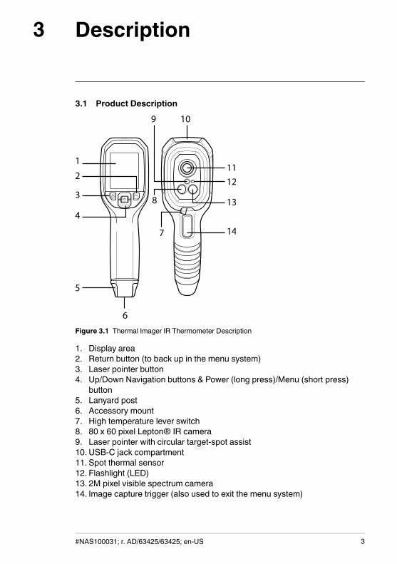
Figure 3.1 Thermal Imager IR Thermometer Description
1. Display area2. Return button (to back up in the menu system)3. Laser pointer button4. Up/Down Navigation buttons & Power (long press)/Menu (short press)
button5. Lanyard post6. Accessory mount7. High temperature lever switch8. 80 x 60 pixel Lepton® IR camera9. Laser pointer with circular target-spot assist10. USB-C jack compartment11. Spot thermal sensor12. Flashlight (LED)13. 2M pixel visible spectrum camera14. Image capture trigger (also used to exit the menu system)
#NAS100031; r. AD/63425/63425; en-US 3
Description3
3.2 Control Button Descriptions
Long press to power ON or OFF
Short press to access the menu system
Return button. Back out to previous screen in menus
Press to scroll upward in the menus
Press to scroll downward in the menus
Press and hold to use the Laser pointer
TRIGGERPull trigger to capture camera image
Pull trigger to exit the menu system
3.3 Display Description
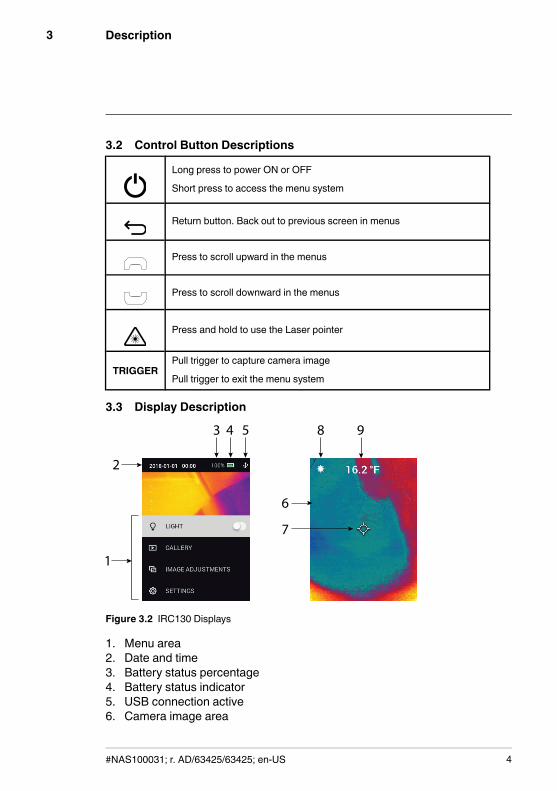
Figure 3.2 IRC130 Displays
1. Menu area2. Date and time3. Battery status percentage4. Battery status indicator5. USB connection active6. Camera image area
#NAS100031; r. AD/63425/63425; en-US 4

Description3
7. Center spot cross-hairs8. Laser Pointer active9. Center spot temperature measurement
#NAS100031; r. AD/63425/63425; en-US 5
Operation4
4.1 Powering the IRC130The IRC130 is powered by a rechargeable lithium battery. Long press thepower button (centre) to switch the unit ON or OFF. If the unit does not powerON, charge the battery by connecting to a 5V/1A rated AC wall charger (notsupplied) using the supplied USB-C cable. The USB-C jack is located in thecompartment at the top of the unit. Do not use the IRC130 while it is charging.When the top flap is closed, the unit is rated IP54 for encapsulation. See Sec-tion 7.2, Battery Considerations and Service for more information.
The IRC130 has an Auto Power OFF (APO) utility that switches it OFF auto-matically if no buttons are pressed for the duration of the selected APO time.Use the menu system (under Device Settings) To set the APO timer. See Sec-tion 5, Programming Menu System, for more information.
4.2 IR Camera and Thermometer
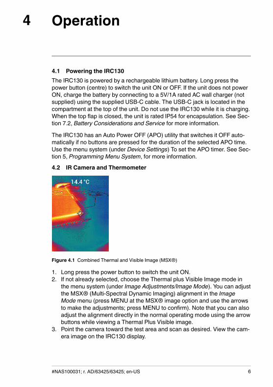
Figure 4.1 Combined Thermal and Visible Image (MSX®)
1. Long press the power button to switch the unit ON.2. If not already selected, choose the Thermal plus Visible Image mode in
the menu system (under Image Adjustments/Image Mode). You can adjustthe MSX® (Multi-Spectral Dynamic Imaging) alignment in the ImageMode menu (press MENU at the MSX® image option and use the arrowsto make the adjustments; press MENU to confirm). Note that you can alsoadjust the alignment directly in the normal operating mode using the arrowbuttons while viewing a Thermal Plus Visible image.
3. Point the camera toward the test area and scan as desired. View the cam-era image on the IRC130 display.
#NAS100031; r. AD/63425/63425; en-US 6
Operation4
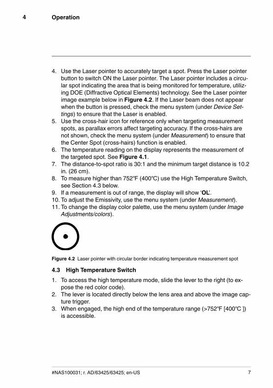
4. Use the Laser pointer to accurately target a spot. Press the Laser pointerbutton to switch ON the Laser pointer. The Laser pointer includes a circu-lar spot indicating the area that is being monitored for temperature, utiliz-ing DOE (Diffractive Optical Elements) technology. See the Laser pointerimage example below in Figure 4.2. If the Laser beam does not appearwhen the button is pressed, check the menu system (under Device Set-tings) to ensure that the Laser is enabled.
5. Use the cross-hair icon for reference only when targeting measurementspots, as parallax errors affect targeting accuracy. If the cross-hairs arenot shown, check the menu system (underMeasurement) to ensure thatthe Center Spot (cross-hairs) function is enabled.
6. The temperature reading on the display represents the measurement ofthe targeted spot. See Figure 4.1.
7. The distance-to-spot ratio is 30:1 and the minimum target distance is 10.2in. (26 cm).
8. To measure higher than 752℉ (400℃) use the High Temperature Switch,see Section 4.3 below.
9. If a measurement is out of range, the display will show ‘OL’.10. To adjust the Emissivity, use the menu system (underMeasurement).11. To change the display color palette, use the menu system (under Image
Adjustments/colors).
Figure 4.2 Laser pointer with circular border indicating temperature measurement spot
4.3 High Temperature Switch1. To access the high temperature mode, slide the lever to the right (to ex-
pose the red color code).2. The lever is located directly below the lens area and above the image cap-
ture trigger.3. When engaged, the high end of the temperature range (>752℉ [400℃ ])
is accessible.
#NAS100031; r. AD/63425/63425; en-US 7
Operation4
4.4 Visible Spectrum Camera
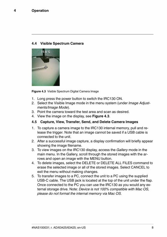
Figure 4.3 Visible Spectrum Digital Camera Image
1. Long press the power button to switch the IRC130 ON.2. Select the Visible Image mode in the menu system (under Image Adjust-
ments/Image Mode).3. Point the camera toward the test area and scan as desired.4. View the image on the display, see Figure 4.3.4.5 Capture, View, Transfer, Send, and Delete Camera Images1. To capture a camera image to the IRC130 internal memory, pull and re-
lease the trigger. Note that an image cannot be saved if a USB cable isconnected to the unit.
2. After a successful image capture, a display confirmation will briefly appearshowing the image filename.
3. To view images on the IRC130 display, access the Gallery mode in themain menu. In the Gallery, scroll through the stored images with the ar-rows and open an image with the MENU button.
4. To delete images, select the DELETE or DELETE ALL FILES command toerase the selected image or all of the stored images. Select CANCEL toexit the menu without making changes.
5. To transfer images to a PC, connect the unit to a PC using the suppliedUSB-C cable. The USB jack is located at the top of the unit under the flap.Once connected to the PC you can use the IRC130 as you would any ex-ternal storage drive. Note: Device is not 100% compatible with Mac OS,please do not format the internal memory via Mac OS.
#NAS100031; r. AD/63425/63425; en-US 8
Programming Menu System5
5.1 Menu System BasicsShort press the MENU button to access the menu system. Use the MENUbutton to switch settings ON or OFF, use the Return button to move to the pre-vious screen, and use the arrows to scroll. In addition, the MENU button isused in some cases to confirm settings. Use the trigger to exit the menusystem.
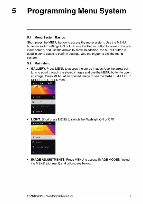
5.2 Main Menu• GALLERY: Press MENU to access the stored images. Use the arrow but-
tons to scroll through the stored images and use the MENU button to openan image. Press MENU at an opened image to see the CANCEL/DELETE/DELETE ALL FILES menu.
• LIGHT: Short press MENU to switch the Flashlight ON or OFF.
• IMAGE ADJUSTMENTS: Press MENU to access IMAGE MODES (includ-ing MSX® alignment) and colors, see below:
#NAS100031; r. AD/63425/63425; en-US 9
Programming Menu System5
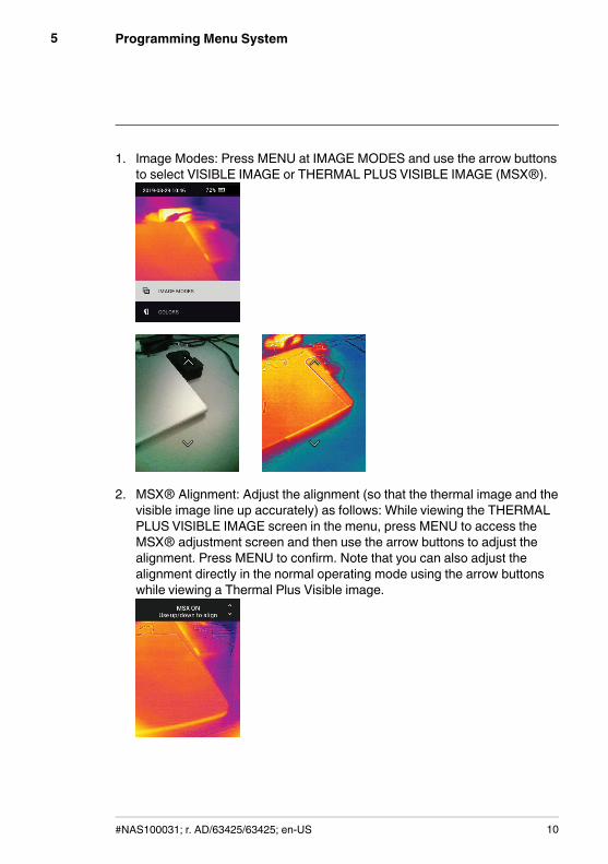
1. Image Modes: Press MENU at IMAGE MODES and use the arrow buttonsto select VISIBLE IMAGE or THERMAL PLUS VISIBLE IMAGE (MSX®).
2. MSX® Alignment: Adjust the alignment (so that the thermal image and thevisible image line up accurately) as follows: While viewing the THERMALPLUS VISIBLE IMAGE screen in the menu, press MENU to access theMSX® adjustment screen and then use the arrow buttons to adjust thealignment. Press MENU to confirm. Note that you can also adjust thealignment directly in the normal operating mode using the arrow buttonswhile viewing a Thermal Plus Visible image.
#NAS100031; r. AD/63425/63425; en-US 10
Programming Menu System5
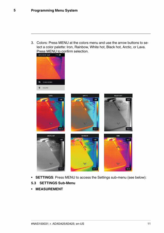
3. Colors: Press MENU at the colors menu and use the arrow buttons to se-lect a color palette: Iron, Rainbow, White hot, Black hot, Arctic, or Lava.Press MENU to confirm selection.
• SETTINGS: Press MENU to access the Settings sub-menu (see below):5.3 SETTINGS Sub-Menu• MEASUREMENT
#NAS100031; r. AD/63425/63425; en-US 11
Programming Menu System5
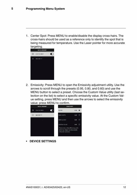
1. Center Spot: Press MENU to enable/disable the display cross-hairs. Thecross-hairs should be used as a reference only to identify the spot that isbeing measured for temperature. Use the Laser pointer for more accuratetargeting.
2. Emissivity: Press MENU to open the Emissivity adjustment utility. Use thearrows to scroll through the presets (0.95, 0.80, and 0.60) and use theMENU button to select a preset. Choose the Custom Value utility (last se-lection on the list) to select a specific emissivity value. At the Custom Val-ue setting, press MENU and then use the arrows to select the emissivityvalue; press MENU to confirm.
• DEVICE SETTINGS
#NAS100031; r. AD/63425/63425; en-US 12
Programming Menu System5
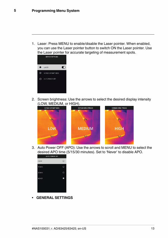
1. Laser: Press MENU to enable/disable the Laser pointer. When enabled,you can use the Laser pointer button to switch ON the Laser pointer. Usethe Laser pointer for accurate targeting of measurement spots.
2. Screen brightness: Use the arrows to select the desired display intensity(LOW, MEDIUM, or HIGH).
3. Auto Power OFF (APO): Use the arrows to scroll and MENU to select thedesired APO time (5/15/30 minutes). Set to ‘Never’ to disable APO.
• GENERAL SETTINGS
#NAS100031; r. AD/63425/63425; en-US 13
Programming Menu System5
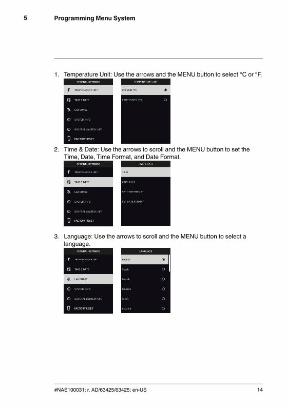
1. Temperature Unit: Use the arrows and the MENU button to select °C or °F.
2. Time & Date: Use the arrows to scroll and the MENU button to set theTime, Date, Time Format, and Date Format.
3. Language: Use the arrows to scroll and the MENU button to select alanguage.
#NAS100031; r. AD/63425/63425; en-US 14
Programming Menu System5
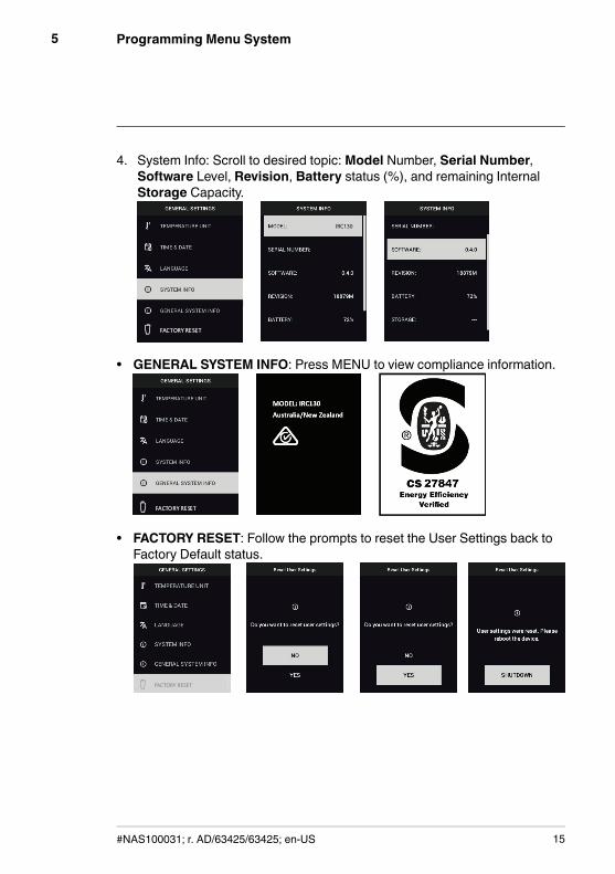
4. System Info: Scroll to desired topic:Model Number, Serial Number,Software Level, Revision, Battery status (%), and remaining InternalStorage Capacity.
• GENERAL SYSTEM INFO: Press MENU to view compliance information.
• FACTORY RESET: Follow the prompts to reset the User Settings back toFactory Default status.
#NAS100031; r. AD/63425/63425; en-US 15
Field Firmware Updates6
The IRC130 includes a USB-C port in the top compartment. The USB port al-lows the user to update the system firmware by first downloading an updatefile from the FLIR website and then connecting the unit to a PC (using the sup-plied USB-C cable) to copy the file. Firmware updates are available fromhttps://support.flir.com.
NOTEThe IRC130 is not 100% compatible with USB-C to USB-C cables. Use only USB-C to USB-A cables. The supplied cable is USB-C to USB-A.
To update the firmware, you will need:
• Access to the website where the update file is located:https://support.flir.com
• The IRC130 to be updated• The update file. Refer to the steps in the next section:6.1 System Firmware Update1. Visit https://support.flir.com to obtain a firmware update file.2. Select the ‘Downloads’ tab and then select ‘Software and Firmware’.3. Search for ‘IRC130’.4. Select and download the firmware update file to the PC.5. With the IRC130 ON connect it to the PC via a USB-C cable (the USB-C
port is located in the top compartment).6. Copy the firmware update file to the IRC130 root directory.7. Eject the IRC130 drive from the PC.8. Disconnect the USB cable from the PC USB port and from the IRC130
USB port.9. Follow the IRC130 display prompts to complete the update.
#NAS100031; r. AD/63425/63425; en-US 16
Maintenance7
7.1 CleaningWipe the housing with a damp cloth as needed. Do not use abrasives or sol-vents. Clean the lenses with a high-quality lens cleaner.
7.2 Battery Considerations and ServiceThe rechargeable lithium battery is not user-serviceable. Please contact usfor service instructions: https://support.flir.com.
For best results, charge the battery immediately after seeing a low battery in-dication using the supplied USB-C cable (with an AC wall charger, not sup-plied). The wall charger must be rated for at least 5V/1A. If the battery isallowed to fully drain, allow 2~3 hours before the charging display appearsafter connecting to an AC charger; a full charge (100%) requires 6 hours, acharge to 90% power requires 4 hours. Charging through a PC USB port isnot recommended.
If the unit is not going to be used for an extended period (> 3 months), itshould be charged to at least 70%, stored at room temperature, and re-charged every 6 months. Failure to do so may result in a battery that cannotbe recharged and that therefore will require service.
7.3 Disposal of Electronic Waste
As with most electronic products, this equipment must be disposed of in anenvironmentally friendly way, and in accordance with existing regulations forelectronic waste. Please contact us for additional information.
7.4 Reset the IRC130If the display freezes or if the unit in any way stops operating normally, pressand hold the up and down buttons for at least 10 seconds. Release the but-tons when the unit switches OFF. After the unit switches OFF, switch it backON again to resume use. No data will be lost by resetting the unit. If problemspersist, contact us for support.
#NAS100031; r. AD/63425/63425; en-US 17
Specifications8
8.1 Imaging and Optical SpecificationsIR resolution 80 x 60 pixels
Digital image enhancement Included
Thermal Sensitivity /NETD < 70 mK
Field of View (FOV) 51° x 66 (H x W)°
Minimum focus distance 0.89 ft. (0.3 m)
Distance-to-Spot ratio 30:1
Dual range operation Range 1: < 752℉ (400℃)
Range 2: > 752℉ (400℃)
For Range 2, the high temperature levermust be engaged
Focus Fixed
Image frequency 8.7 Hz
8.2 Detector SpecificationsFocal plane array /Spectral response range Uncooled microbolometer /7.5 ~ 14 μm
Detector pitch 12 μm
8.3 Image Presentation SpecificationsDisplay resolution 320 x 240 pixels
Screen size 2.4 in. (portrait)
Viewing angle 80°
Color depth 24 bit
Aspect ratio 4:3
Display type TFT technology
Image adjustment Automatic
Image modes Thermal MSX® (Multi-Spectral DynamicImaging) and Visible Spectrum modes.
#NAS100031; r. AD/63425/63425; en-US 18
Specifications8
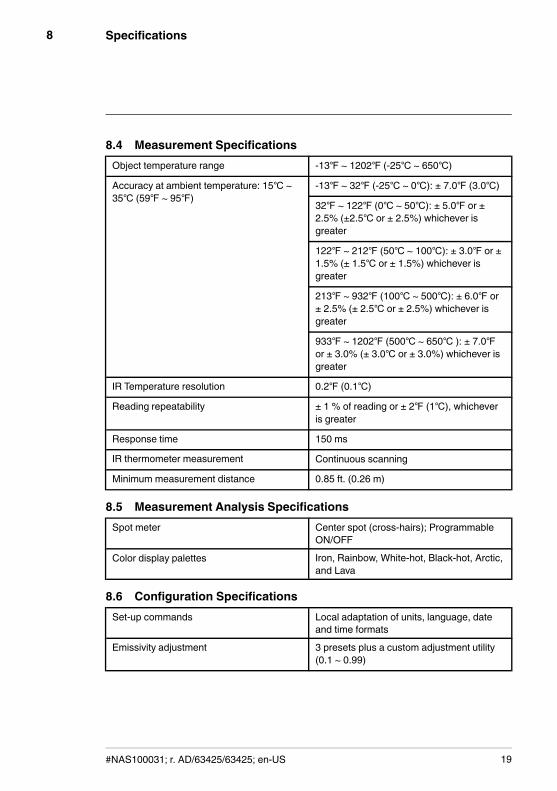
8.4 Measurement SpecificationsObject temperature range -13℉ ~ 1202℉ (-25℃ ~ 650℃)
Accuracy at ambient temperature: 15℃ ~35℃ (59℉ ~ 95℉)
-13℉ ~ 32℉ (-25℃ ~ 0℃): ± 7.0℉ (3.0℃)
32℉ ~ 122℉ (0℃ ~ 50℃): ± 5.0℉ or ±2.5% (±2.5℃ or ± 2.5%) whichever isgreater
122℉ ~ 212℉ (50℃ ~ 100℃): ± 3.0℉ or ±1.5% (± 1.5℃ or ± 1.5%) whichever isgreater
213℉ ~ 932℉ (100℃ ~ 500℃): ± 6.0℉ or± 2.5% (± 2.5℃ or ± 2.5%) whichever isgreater
933℉ ~ 1202℉ (500℃ ~ 650℃ ): ± 7.0℉or ± 3.0% (± 3.0℃ or ± 3.0%) whichever isgreater
IR Temperature resolution 0.2℉ (0.1℃)
Reading repeatability ± 1 % of reading or ± 2℉ (1℃), whicheveris greater
Response time 150 ms
IR thermometer measurement Continuous scanning
Minimum measurement distance 0.85 ft. (0.26 m)
8.5 Measurement Analysis SpecificationsSpot meter Center spot (cross-hairs); Programmable
ON/OFF
Color display palettes Iron, Rainbow, White-hot, Black-hot, Arctic,and Lava
8.6 Configuration SpecificationsSet-up commands Local adaptation of units, language, date
and time formats
Emissivity adjustment 3 presets plus a custom adjustment utility(0.1 ~ 0.99)
#NAS100031; r. AD/63425/63425; en-US 19
Specifications8
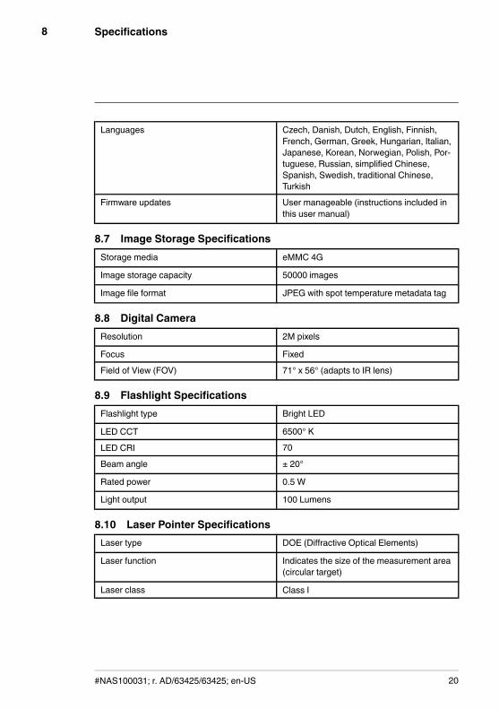
Languages Czech, Danish, Dutch, English, Finnish,French, German, Greek, Hungarian, Italian,Japanese, Korean, Norwegian, Polish, Por-tuguese, Russian, simplified Chinese,Spanish, Swedish, traditional Chinese,Turkish
Firmware updates User manageable (instructions included inthis user manual)
8.7 Image Storage SpecificationsStorage media eMMC 4G
Image storage capacity 50000 images
Image file format JPEG with spot temperature metadata tag
8.8 Digital CameraResolution 2M pixels
Focus Fixed
Field of View (FOV) 71° x 56° (adapts to IR lens)
8.9 Flashlight SpecificationsFlashlight type Bright LED
LED CCT 6500° K
LED CRI 70
Beam angle ± 20°
Rated power 0.5 W
Light output 100 Lumens
8.10 Laser Pointer SpecificationsLaser type DOE (Diffractive Optical Elements)
Laser function Indicates the size of the measurement area(circular target)
Laser class Class I
#NAS100031; r. AD/63425/63425; en-US 20
Specifications8
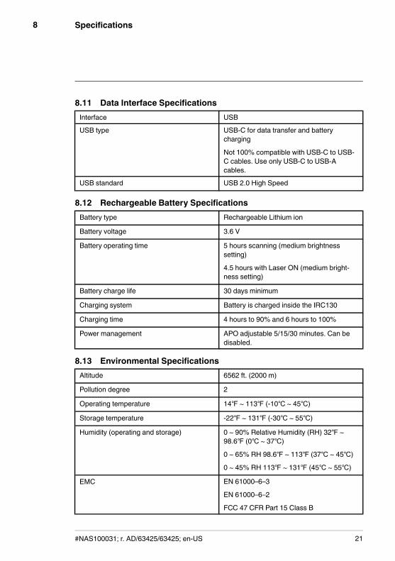
8.11 Data Interface SpecificationsInterface USB
USB type USB-C for data transfer and batterycharging
Not 100% compatible with USB-C to USB-C cables. Use only USB-C to USB-Acables.
USB standard USB 2.0 High Speed
8.12 Rechargeable Battery SpecificationsBattery type Rechargeable Lithium ion
Battery voltage 3.6 V
Battery operating time 5 hours scanning (medium brightnesssetting)
4.5 hours with Laser ON (medium bright-ness setting)
Battery charge life 30 days minimum
Charging system Battery is charged inside the IRC130
Charging time 4 hours to 90% and 6 hours to 100%
Power management APO adjustable 5/15/30 minutes. Can bedisabled.
8.13 Environmental SpecificationsAltitude 6562 ft. (2000 m)
Pollution degree 2
Operating temperature 14℉ ~ 113℉ (-10℃ ~ 45℃)
Storage temperature -22℉ ~ 131℉ (-30℃ ~ 55℃)
Humidity (operating and storage) 0 ~ 90% Relative Humidity (RH) 32℉ ~98.6℉ (0℃ ~ 37℃)
0 ~ 65% RH 98.6℉ ~ 113℉ (37℃ ~ 45℃)
0 ~ 45% RH 113℉ ~ 131℉ (45℃ ~ 55℃)
EMC EN 61000–6–3
EN 61000–6–2
FCC 47 CFR Part 15 Class B
#NAS100031; r. AD/63425/63425; en-US 21
Specifications8
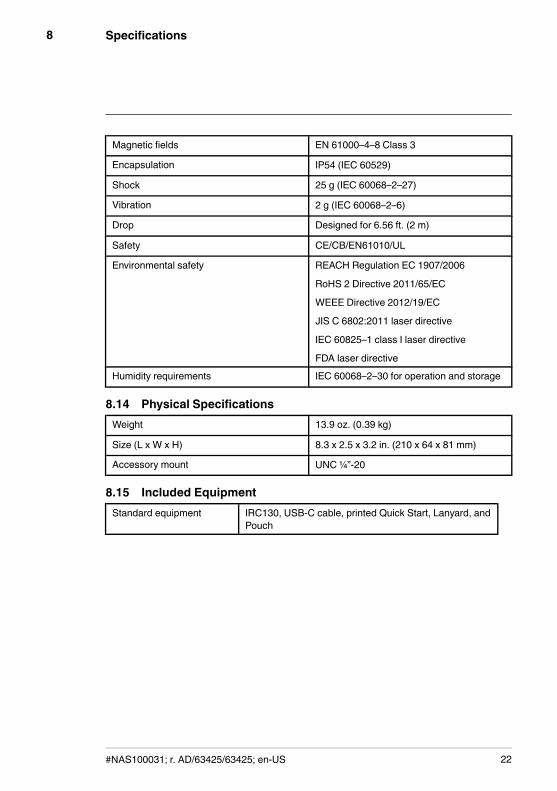
Magnetic fields EN 61000–4–8 Class 3
Encapsulation IP54 (IEC 60529)
Shock 25 g (IEC 60068–2–27)
Vibration 2 g (IEC 60068–2–6)
Drop Designed for 6.56 ft. (2 m)
Safety CE/CB/EN61010/UL
Environmental safety REACH Regulation EC 1907/2006
RoHS 2 Directive 2011/65/EC
WEEE Directive 2012/19/EC
JIS C 6802:2011 laser directive
IEC 60825–1 class I laser directive
FDA laser directive
Humidity requirements IEC 60068–2–30 for operation and storage
8.14 Physical SpecificationsWeight 13.9 oz. (0.39 kg)
Size (L x W x H) 8.3 x 2.5 x 3.2 in. (210 x 64 x 81 mm)
Accessory mount UNC ¼”-20
8.15 Included EquipmentStandard equipment IRC130, USB-C cable, printed Quick Start, Lanyard, and
Pouch
#NAS100031; r. AD/63425/63425; en-US 22
Warranty and CustomerSupport
9
9.1 Two-Year WarrantyFLIR Systems, Inc. warrants this Extech brand instrument to be free of defectsin parts and workmanship for two years from date of shipment (a six-monthlimited warranty applies to sensors and cables). To view the full warranty textplease visit: https://www.extech.com/warranty.
9.2 Repair and Calibration ServicesFLIR Systems, Inc. offers calibration and repair services for the Extech brandproducts we sell. We offer NIST traceable calibration for most of our products.Contact us for information on calibration and repair availability. Annual calibra-tions should be performed to verify meter performance and accuracy. Productspecifications are subject to change without notice. Please visit our websitefor the most up-to-date product information: www.extech.com.
9.3 Customer SupportCustomer Support Telephone:
U.S. (866) 477-3687
International +1 (603) 324-7800
Calibration, Repair, and Returns email: [email protected]
Technical Support: https://support.flir.com
Corporate Headquarters: FLIR Systems, Inc., 27700 SW Parkway Ave., Wil-sonville, OR 97070, USA
opyright © FLIR Systems, Inc.
All rights reserved including the right of reproduction in whole or in part in any form.
www.extech.com
#NAS100031; r. AD/63425/63425; en-US 23


