Su Kaynaklı Isı Pompası / WSHPSudan Havaya Isı Pompası
Isı Pompaları
Kimdir ?
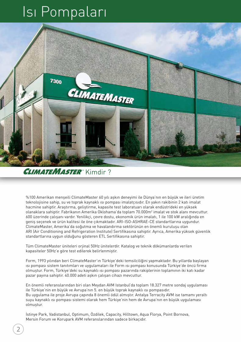
%100 Amerikan menşeili ClimateMaster 60 yılı aşkın deneyimi ile Dünya’nın en büyük ve ileri üretim teknolojisine sahip, su ve toprak kaynaklı ısı pompası imalatçısıdır. En yakın rakibinin 2 katı imalat hacmine sahiptir. Araştırma, geliştirme, kapasite test laboratuarı olarak endüstrideki en yüksek olanaklara sahiptir. Fabrikanın Amerika Oklohama’da toplam 70.000m2 imalat ve stok alanı mevcuttur. 600 üzerinde çalışanı vardır. Yenilikçi, çevre dostu, ekonomik ürün imalatı, 1 ile 100 kW aralığında en geniş seçenek ve ürün kalitesi ile öne çıkmaktadır. ARI-ISO-ASHRAE-CE standartlarına uygundur. ClimateMaster, Amerika’da soğutma ve havalandırma sektörünün en önemli kuruluşu olan ARI (Air Conditioning and Refrigeration Institute) Sertifikasına sahiptir. Ayrıca, Amerika yüksek güvenlik standartlarına uygun olduğunu gösteren ETL Sertifikasına sahiptir.
Tüm ClimateMaster üniteleri orjinal 50Hz ünitelerdir. Katalog ve teknik dökümanlarda verilen kapasiteler 50Hz’e göre test edilerek belirlenmiştir.
Form, 1993 yılından beri ClimateMaster’ın Türkiye’deki temsilciliğini yapmaktadır. Bu yıllarda başlayan ısı pompası sistem tanıtımları ve uygulamaları ile Form ısı pompası konusunda Türkiye’de öncü firma olmuştur. Form, Türkiye’deki su kaynaklı ısı pompası pazarında rakiplerinin toplamının iki katı kadar pazar payına sahiptir. 40.000 adeti aşkın çalışan cihazı mevcuttur.
En önemli referanslarından biri olan Meydan AVM Istanbul’da toplam 18.327 metre sondaj uygulaması ile Türkiye’nin en büyük ve Avrupa’nın 5. en büyük toprak kaynaklı ısı pompasıdır. Bu uygulama ile proje Avrupa çapında 8 önemli ödül almıştır. Antalya Terracity AVM ise tamamı yeraltı suyu kaynaklı ısı pompası sistemi olarak hem Türkiye’nin hem de Avrupa’nın en büyük uygulaması olmuştur.
İstinye Park, Vadistanbul, Optimum, Özdilek, Capacity, Hilltown, Aqua Florya, Point Bornova, Mersin Forum ve Korupark AVM referanslarından sadece birkaçıdır.
İçindekilerISI POMPASI GENEL SAYFA
Isı Pompası Nedir? 04
10-13
0506-0708-09
Isı Pompası Avantajları Isı Pompası Çalışma Prensipleri Isı Pompası Sistem Uygulamaları
SUDAN HAVAYA ISI POMPASI (CLIMATEMASTER) SAYFA
TC Compact Genel Özellikler 14-25TC Compact Teknik Bilgiler
26
TC Compact Large Teknik Bilgiler
Aksesuarlar27-2829-32
TC Compact Large Genel Özellikler
33-36SU KAYNAKLI PAKET KLİMA (LENNOX)
37KAPALI TİP SOĞUTMA KULESİ (DECSA)
38-39REFERANSLARIMIZ
Neden Su Kaynaklı Sistem?
Isı Pompası Nedir? / Neden Isı Pompası?
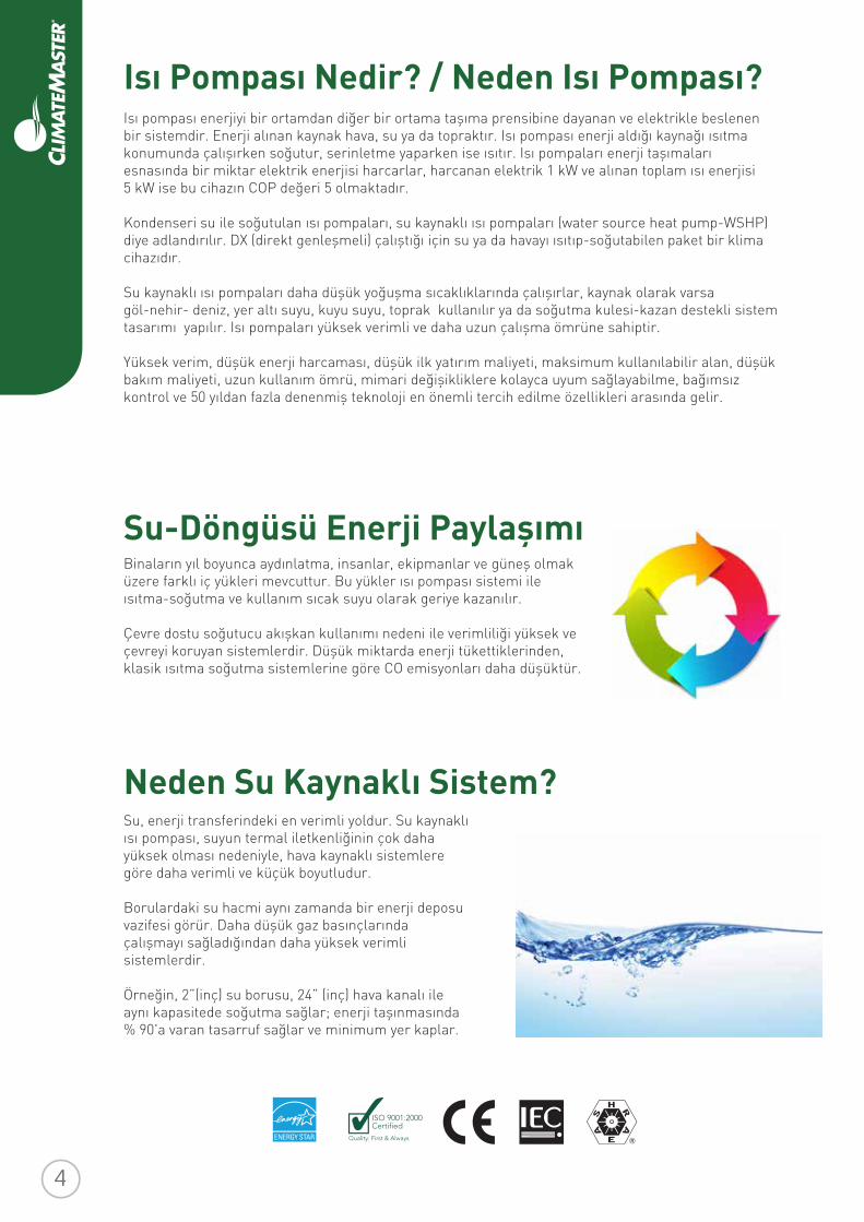
Su-Döngüsü Enerji Paylaşımı Binaların yıl boyunca aydınlatma, insanlar, ekipmanlar ve güneş olmak üzere farklı iç yükleri mevcuttur. Bu yükler ısı pompası sistemi ile ısıtma-soğutma ve kullanım sıcak suyu olarak geriye kazanılır.
Çevre dostu soğutucu akışkan kullanımı nedeni ile verimliliği yüksek ve çevreyi koruyan sistemlerdir. Düşük miktarda enerji tükettiklerinden, klasik ısıtma soğutma sistemlerine göre CO emisyonları daha düşüktür.
Isı pompası enerjiyi bir ortamdan diğer bir ortama taşıma prensibine dayanan ve elektrikle beslenen bir sistemdir. Enerji alınan kaynak hava, su ya da topraktır. Isı pompası enerji aldığı kaynağı ısıtma konumunda çalışırken soğutur, serinletme yaparken ise ısıtır. Isı pompaları enerji taşımaları esnasında bir miktar elektrik enerjisi harcarlar, harcanan elektrik 1 kW ve alınan toplam ısı enerjisi 5 kW ise bu cihazın COP değeri 5 olmaktadır.
Kondenseri su ile soğutulan ısı pompaları, su kaynaklı ısı pompaları (water source heat pump-WSHP) diye adlandırılır. DX (direkt genleşmeli) çalıştığı için su ya da havayı ısıtıp-soğutabilen paket bir klima cihazıdır.
Su kaynaklı ısı pompaları daha düşük yoğuşma sıcaklıklarında çalışırlar, kaynak olarak varsa göl-nehir- deniz, yer altı suyu, kuyu suyu, toprak kullanılır ya da soğutma kulesi-kazan destekli sistem tasarımı yapılır. Isı pompaları yüksek verimli ve daha uzun çalışma ömrüne sahiptir.
Yüksek verim, düşük enerji harcaması, düşük ilk yatırım maliyeti, maksimum kullanılabilir alan, düşük bakım maliyeti, uzun kullanım ömrü, mimari değişikliklere kolayca uyum sağlayabilme, bağımsız kontrol ve 50 yıldan fazla denenmiş teknoloji en önemli tercih edilme özellikleri arasında gelir.
Su, enerji transferindeki en verimli yoldur. Su kaynaklı ısı pompası, suyun termal iletkenliğinin çok daha yüksek olması nedeniyle, hava kaynaklı sistemlere göre daha verimli ve küçük boyutludur.
Borulardaki su hacmi aynı zamanda bir enerji deposu vazifesi görür. Daha düşük gaz basınçlarında çalışmayı sağladığından daha yüksek verimli sistemlerdir.
Örneğin, 2”(inç) su borusu, 24” (inç) hava kanalı ile aynı kapasitede soğutma sağlar; enerji taşınmasında % 90'a varan tasarruf sağlar ve minimum yer kaplar.
Kullanıcı / İşletme Açısından
Mimari / Uygulama Açısından
Yatırımcı / İlk Yatırım Açısından
Su Kaynaklı Isı Pompası Avantajları
İlk yatırım sadece soğutma kulesi, daha küçük kazan ve 2 borulu izolasyonsuz tesisat borulaması içerir. Aynı anda bağımsız ısıtma ve soğutma için gerekli ilk yatırım maliyeti, alternatiflerine göre minimumdur. Mahallerdeki cihazlar kullanıcılar tarafından alınabilir. İzolasyona ihtiyaç duyulmaz.Hızlı kurulum ile zamandan tasarruf sağlar.Farklı sistemlerin bir arada kullanılmasını ortadan kaldırır. Türkiye ve Dünya’da denenmiş bir teknolojidir. Bina otomasyonu ile uyumlu çalışır, maksimum verimlilik sağlar.Çevre mevzuatlarına uygun olup uzun süre sorunsuz kullanılabilir. Uzun ömürlüdür ve yeşil bina sertifakaları için puan kazandırır.
Bina dışında sadece soğutma kulesi bulunur, çok sayıda dış ünite kullanılmaz ve bu sayede yerden tasarruf sağlanır ve görüntü kirliliği önlenir.İhtiyaç duyulan teknik oda daha küçüktür, alandan tasarruf sağlar.2 borulu sistem ile aynı anda bağımsız soğutma/ısıtma ve ısı geri kazanım yapılır. Aynı konfor diğer sistemlerde 4 borulu veya 3 borulu sistem çözümü ile yapılmaktadır.Esnek tasarım sayesinde, birbirinden etkilenmeden farklı zamanlarda montaj yapılabilmektedir.İç dekorasyona uygun olarak yatay-dikey tip ünitelerle çözüm imkanı mevcuttur.Wshp su hattı boruları siyah dikişli borudur, bakır boru olmadığından kaynak problemi yoktur.Geniş kanal şaftlarına ihtiyaç yoktur. Boru hattı metraj sınırlaması yoktur.
Her cihaz / kullanıcı birbirinden bağımsız olarak aynı anda soğutma ve ısıtma yapabilir. Aynı anda soğutma ve ısıtma yapıldığı zamanlarda sistem kendi içinde ısı geri kazanım yapar. Bu sayede yüksek verimlilik sağlanır ve işletme maliyetleri minimum olur.Her kullanıcı harcadığı kadar enerji bedeli öder.İhtiyaca göre kapasite artırımı ve azaltılması mümkündür ve diğer mahaller bu değişimden etkilenmez.Devre dışı kalmaktan korunma sağlar.Bina içinde soğutucu akışkan taşınmaz. Bina otomasyonu ile uyumlu çalışabilir.Gelişmiş, programlanabilir, arıza kodu görülebilen termostat ile kolay kullanım sağlar.Geniş ve tecrübeli servis ağı ile hızlı servis ve kaliteli bakım hizmeti sağlar.
Nasıl Çalışır ?
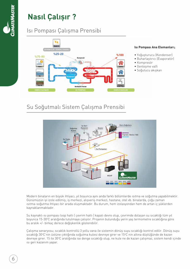
Modern binaların en büyük ihtiyacı, yıl boyunca aynı anda farklı bölümlerde ısıtma ve soğutma yapabilmektir. Günümüzün iyi izole edilmiş; iş merkezi, alışveriş merkezi, hastane, otel vb. binalarda, çoğu zaman ısıtma-soğutma ihtiyacı bir arada oluşmaktadır. Bu durum, hem izolasyondan hem de artan iç yüklerden kaynaklanmaktadır.
Su kaynaklı ısı pompası loop hattı ( çevrim hattı ) kapalı devre olup, çevrimde dolaşan su sıcaklığı tüm yıl boyunca 15-30oC aralığında tutulmaya çalışılır. Projenin bulunduğu yerin yaş termometre sıcaklığına göre bu aralık +/- birkaç derece değişkenlik gösterebilir.
Çalışma senaryosu; sıcaklık kontrollü 3 yollu vana ile sistemin dönüş suyu sıcaklığı kontrol edilir. Dönüş suyu sıcaklığı 30oC’nin üstüne çıktığında soğutma kulesi devreye girer ve 15oC nin altına düştüğünde de kazan devreye girer. 15 ile 30oC aralığında ise denge sıcaklığı olup, ne kule ne de kazan çalışmaz, sistem kendi içinde ısı geri kazanım yapar.
Isı Pompası Ana Elemanları;
• Yoğuşturucu (Kondenser)• Buharlaştırıcı (Evaporatör)• Kompresör• Genleşme valfi• Soğutucu akışkan
Isı Pompası Çalışma Prensibi
Su Soğutmalı Sistem Çalışma Prensibi
Su Tankı
SoğutmaKulesi
Isı GeriKazanım
Decsa
Boyler
Kuru Soğutucu
Toprak / Deniz / Göl
Su Pompaları
WSHP
10ºC 13ºC 15ºC 20ºC 29ºC 35ºC
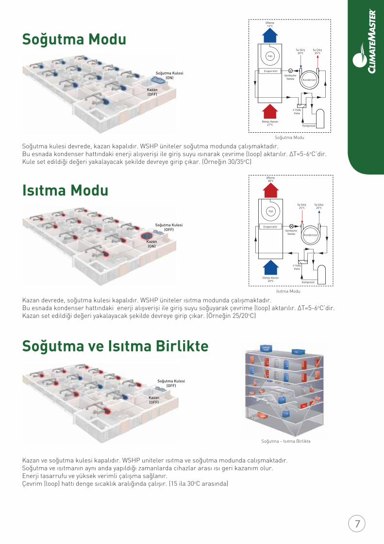
Soğutma kulesi devrede, kazan kapalıdır. WSHP üniteler soğutma modunda çalışmaktadır.Bu esnada kondenser hattındaki enerji alışverişi ile giriş suyu ısınarak çevrime (loop) aktarılır. ∆T=5-6oC’dir.Kule set edildiği değeri yakalayacak şekilde devreye girip çıkar. (Örneğin 30/35oC)
Soğutma Modu
Kondenser
Evaporatör
Isıtma Modu
Soğutma ve Isıtma Birlikte
Soğutma Modu
Kazan devrede, soğutma kulesi kapalıdır. WSHP üniteler ısıtma modunda çalışmaktadır.Bu esnada kondenser hattındaki enerji alışverişi ile giriş suyu soğuyarak çevrime (loop) aktarılır. ∆T=5-6oC’dir.Kazan set edildiği değeri yakalayacak şekilde devreye girip çıkar. (Örneğin 25/20oC)
Isı Pompası Ana Elemanları;
• Yoğuşturucu (Kondenser)• Buharlaştırıcı (Evaporatör)• Kompresör• Genleşme valfi• Soğutucu akışkan
Kazan ve soğutma kulesi kapalıdır. WSHP uniteler ısıtma ve soğutma modunda calışmaktadır.Soğutma ve ısıtmanın aynı anda yapıldığı zamanlarda cihazlar arası ısı geri kazanım olur. Enerji tasarrufu ve yüksek verimli çalışma sağlanır. Çevrim (loop) hattı denge sıcaklık aralığında çalışır. (15 ila 30oC arasında)
Soğutma Kulesi(OFF)
Kazan(ON)
Soğutma Kulesi(OFF)
Kazan(OFF)
Soğutma Kulesi(ON)
Kazan(OFF)
Evaporatör
Isıtma Modu
Kondenser
Soğutma - Isıtma Birlikte
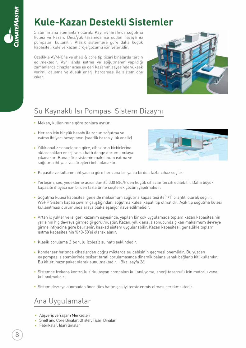
Kule-Kazan Destekli Sistemler
Sistemin ana elemanları olarak; Kaynak tarafında soğutma kulesi ve kazan, Bina/yük tarafında ise sudan havaya ısı pompaları kullanılır. Klasik sistemlere göre daha küçük kapasiteli kule ve kazan proje çözümü için yeterlidir.
Özellikle AVM-Ofis ve shell & core tip ticari binalarda tercih edilmektedir. Aynı anda ısıtma ve soğutmanın yapıldığı zamanlarda cihazlar arası ısı geri kazanım sayesinde yüksek verimli çalışma ve düşük enerji harcaması ile sistem öne çıkar.
Mekan, kullanımına göre zonlara ayrılır.
Her zon için bir yük hesabı ile zonun soğutma veısıtma ihtiyacı hesaplanır. (saatlik bazda yıllık analiz)
Yıllık analiz sonuçlarına göre, cihazların birbirlerine aktaracakları enerji ve su hattı denge durumu ortaya çıkacaktır. Buna göre sistemin maksimum ısıtma ve soğutma ihtiyacı ve süreçleri belli olacaktır.
Kapasite ve kullanım ihtiyacına göre her zona bir ya da birden fazla cihaz seçilir.
Yerleşim, ses, yedekleme açısından 60,000 Btu/h’den küçük cihazlar tercih edilebilir. Daha büyükkapasite ihtiyacı için birden fazla ünite seçilerek çözüm yapılmalıdır.
Soğutma kulesi kapasitesi genelde maksimum soğutma kapasitesi ile(1/1) orantılı olarak seçilir. WSHP Sistem kapalı çevrim çalıştığından, soğutma kulesi kapalı tip olmalıdır. Açık tip soğutma kulesi kullanılması durumunda araya plaka eşanjör ilave edilmelidir.
Artan iç yükler ve ısı geri kazanım sayesinde, yapılan bir çok uygulamada toplam kazan kapasitesinin yarısının hiç devreye girmediği görülmüştür. Kazan, yıllık analiz sonucunda çıkan maksimum devreye girme ihtiyacina göre belirlenir, kaskad sistem uygulanabilir. Kazan kapasitesi, genellikle toplam ısıtma kapasitesinin %40-50’si olarak alınır.
Klasik borulama 2 borulu izolesiz su hattı şeklindedir.
Kondenser hattında cihazlardan doğru miktarda su debisinin geçmesi önemlidir. Bu yüzden ısı pompası sistemlerinde tesisat tarafı borulamasında dinamik balans vanalı bağlantı kiti kullanılır. Bu kitler, hazır paket olarak sunulmaktadır. (Bkz; sayfa 26)
Sistemde frekans kontrollu sirkulasyon pompaları kullanılıyorsa, enerji tasarrufu için motorlu vana kullanılmalıdır.
Sistem devreye alınmadan önce tüm hattın çok iyi temizlenmiş olması gerekmektedir.
Su Kaynaklı Isı Pompası Sistem Dizaynı
Ana Uygulamalar
Alışveriş ve Yaşam MerkezleriShell and Core Binalar, Ofisler, Ticari BinalarFabrikalar, İdari Binalar
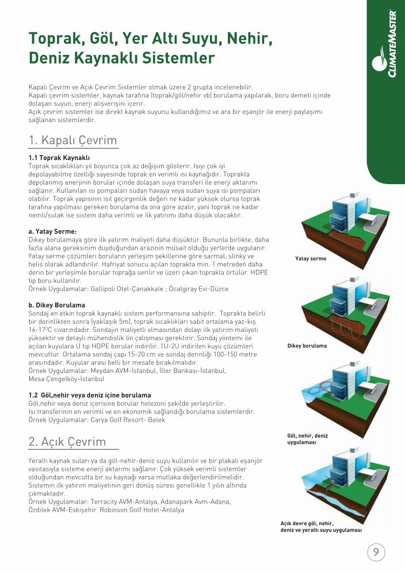
Kapalı Çevrim ve Açık Çevrim Sistemler olmak üzere 2 grupta incelenebilir. Kapalı çevrim sistemler, kaynak tarafına (toprak/göl/nehir vb) borulama yapılarak, boru demeti içinde dolaşan suyun, enerji alışverişini içerir. Açık çevrim sistemler ise direkt kaynak suyunu kullandığımız ve ara bir eşanjör ile enerji paylaşımı sağlanan sistemlerdir.
1.1 Toprak KaynaklıToprak sıcaklıkları yıl boyunca çok az değişim gösterir. Isıyı çok iyi depolayabilme özelliği sayesinde toprak en verimli ısı kaynağıdır. Toprakta depolanmış enerjinin borular içinde dolaşan suya transferi ile enerji aktarımı sağlanır. Kullanılan ısı pompaları sudan havaya veya sudan suya ısı pompaları olabilir. Toprak yapısının ısıl geçirgenlik değeri ne kadar yüksek olursa toprak tarafına yapılması gereken borulama da ona göre azalır, yani toprak ne kadar nemli/sulak ise sistem daha verimli ve ilk yatırımı daha düşük olacaktır.
a. Yatay Serme: Dikey borulamaya göre ilk yatırım maliyeti daha düşüktür. Bununla birlikte; daha fazla alana gereksinim duyduğundan arazinin müsait olduğu yerlerde uygulanır. Yatay serme çözümleri boruların yerleşim şekillerine göre sarmal, slinky ve helis olarak adlandırılır. Hafriyat sonucu açılan toprakta min. 1 metreden daha derin bir yerleşimle borular toprağa serilir ve üzeri çıkan toprakla örtülür. HDPE tip boru kullanılır.Örnek Uygulamalar: Gallipoli Otel-Çanakkale ; Öcalgiray Evi-Düzce
b. Dikey BorulamaSondaj en etkin toprak kaynaklı sistem performansına sahiptir. Toprakta belirli bir derinlikten sonra (yaklaşık 5m), toprak sıcaklıkları sabit ortalama yaz-kış 16-17OC civarındadır. Sondajın maliyetli olmasından dolayı ilk yatırım maliyeti yüksektir ve detaylı mühendislik ön çalışması gerektirir. Sondaj yöntemi ile açılan kuyulara U tip HDPE borular indirilir. 1U-2U indirilen kuyu çözümleri mevcuttur. Ortalama sondaj çapı 15-20 cm ve sondaj derinliği 100-150 metre arasındadır. Kuyular arası belli bir mesafe bırakılmalıdır.Örnek Uygulamalar: Meydan AVM-İstanbul, İller Bankası-İstanbul, Mesa Çengelköy-İstanbul
1.2 Göl,nehir veya deniz içine borulamaGöl,nehir veya deniz içerisine borular helezoni şekilde yerleştirilir. Isı transferinin en verimli ve en ekonomik sağlandığı borulama sistemlerdir.Örnek Uygulamalar: Carya Golf Resort- Belek
Yeraltı kaynak suları ya da göl-nehir-deniz suyu kullanılır ve bir plakalı eşanjör vasıtasıyla sisteme enerji aktarımı sağlanır. Çok yüksek verimli sistemler olduğundan mevcutta bir su kaynağı varsa mutlaka değerlendirilmelidir. Sistemin ilk yatırım maliyetinin geri dönüş süresi genellikle 1 yılın altında çıkmaktadır. Örnek Uygulamalar: Terracity AVM-Antalya, Adanapark Avm-Adana, Özdilek AVM-Eskişehir Robinson Golf Hotel-Antalya
1. Kapalı Çevrim
2. Açık Çevrim
Toprak, Göl, Yer Altı Suyu, Nehir, Deniz Kaynaklı Sistemler
Yatay serme
Dikey borulama
Göl, nehir, deniz uygulaması
Açık devre göl, nehir, deniz ve yeraltı suyu uygulaması
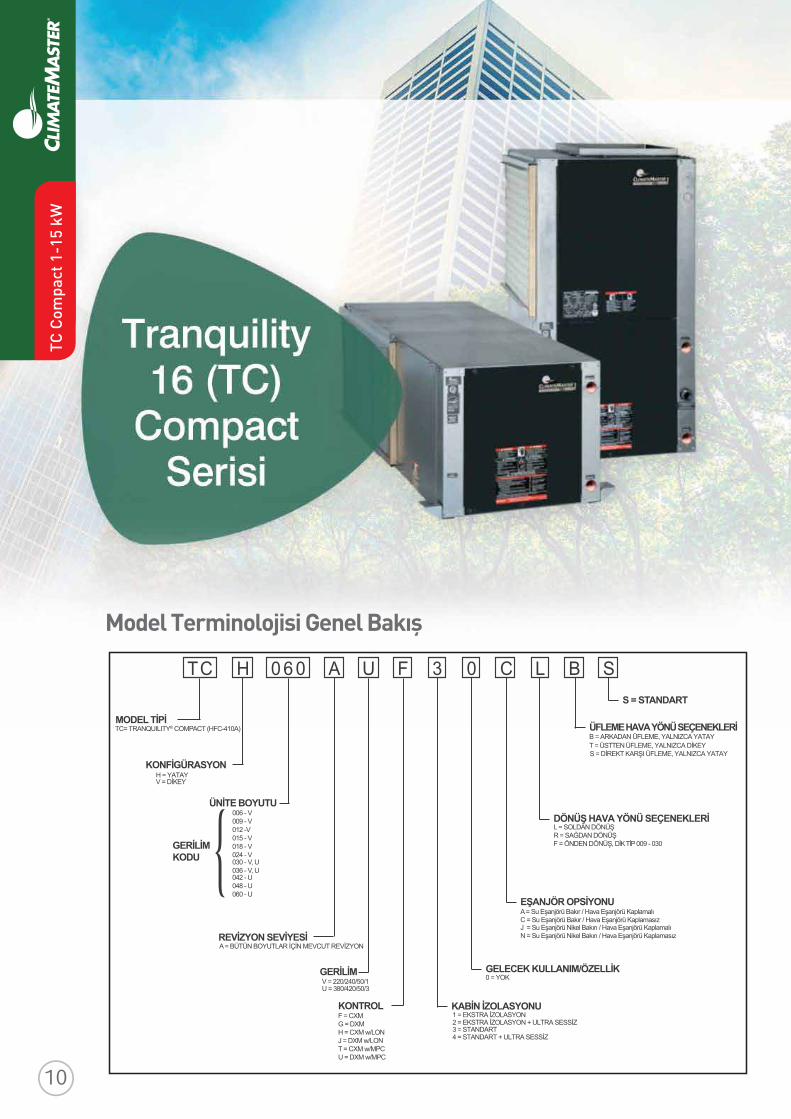
Model Terminolojisi Genel Bakış
T C H A0 6 0 FU 3 0 C L B S8
TC= TRANQUILITY® COMPACT (HFC-410A)MODEL TİPİ
H = YATAYKONFİGÜRASYON
V = DİKEY
ÜNİTE BOYUTU006 - V009 - V012 -V015 - V018 - V024 - V
REVİZYON SEVİYESİA = BÜTÜN BOYUTLAR İÇİN MEVCUT REVİZYON
GERİLİM
F = CXMKONTROL
G = DXMH = CXM w/LONJ = DXM w/LONT = CXM w/MPCU = DXM w/MPC
1 = EKSTRA İZOLASYONKABİN İZOLASYONU2 = EKSTRA İZOLASYON + ULTRA SESSİZ
0 = YOKGELECEK KULLANIM/ÖZELLİK
A = Su Eşanjörü Bakır / Hava Eşanjörü KaplamalıEŞANJÖR OPSİYONUC = Su Eşanjörü Bakır / Hava Eşanjörü Kaplamasız
L = SOLDAN DÖNÜŞDÖNÜŞ HAVA YÖNÜ SEÇENEKLERİR = SAĞDAN DÖNÜŞF = ÖNDEN DÖNÜŞ, DİK TİP 009 - 030
B = ARKADAN ÜFLEME, YALNIZCA YATAYÜFLEME HAVA YÖNÜ SEÇENEKLERİ
T = ÜSTTEN ÜFLEME, YALNIZCA DİKEYS = DİREKT KARŞI ÜFLEME, YALNIZCA YATAY
S = STANDART
J = Su Eşanjörü Nikel Bakırı / Hava Eşanjörü KaplamalıN = Su Eşanjörü Nikel Bakırı / Hava Eşanjörü Kaplamasız
3 = STANDART4 = STANDART + ULTRA SESSİZ
GERİLİMKODU 030 - V, U
036 - V, U042 - U048 - U060 - U
V = 220/240/50/1U = 380/420/50/3
TC C
ompa
ct 1
-15
kW
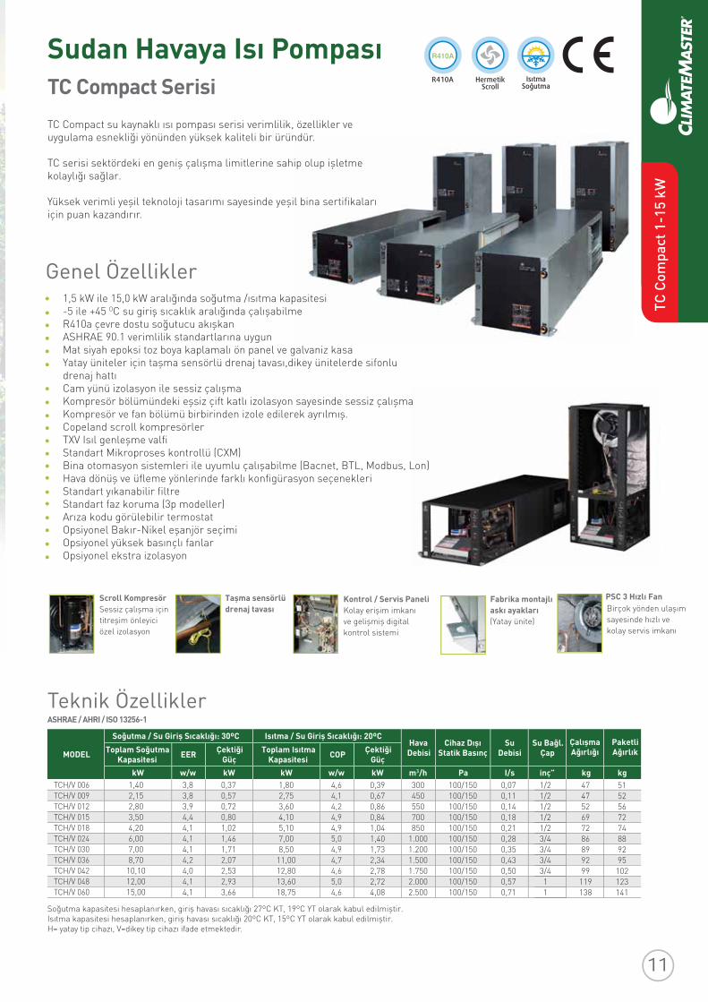
TC Compact Serisi
Sudan Havaya Isı Pompası
Fabrika montajlı PSC 3 Hızlı Fan
askı ayaklarıScroll KompresörSessiz çalışma için titreşim önleyici özel izolasyon
Kontrol / Servis PaneliKolay erişim imkanı
(Yatay ünite)ve gelişmiş digital kontrol sistemi
Taşma sensörlü drenaj tavası
Genel Özellikler
TC Compact su kaynaklı ısı pompası serisi verimlilik, özellikler ve uygulama esnekliği yönünden yüksek kaliteli bir üründür.
TC serisi sektördeki en geniş çalışma limitlerine sahip olup işletme kolaylığı sağlar.
Yüksek verimli yeşil teknoloji tasarımı sayesinde yeşil bina sertifikalarıiçin puan kazandırır.
Birçok yönden ulaşım sayesinde hızlı ve kolay servis imkanı
1,5 kW ile 15,0 kW aralığında soğutma /ısıtma kapasitesi-5 ile +45 OC su giriş sıcaklık aralığında çalışabilmeR410a çevre dostu soğutucu akışkanASHRAE 90.1 verimlilik standartlarına uygunMat siyah epoksi toz boya kaplamalı ön panel ve galvaniz kasa Yatay üniteler için taşma sensörlü drenaj tavası,dikey ünitelerde sifonlu drenaj hattı Cam yünü izolasyon ile sessiz çalışma Kompresör bölümündeki eşsiz çift katlı izolasyon sayesinde sessiz çalışma Kompresör ve fan bölümü birbirinden izole edilerek ayrılmış. Copeland scroll kompresörler TXV Isıl genleşme valfi Standart Mikroproses kontrollü (CXM)Bina otomasyon sistemleri ile uyumlu çalışabilme (Bacnet, BTL, Modbus, Lon)Hava dönüş ve üfleme yönlerinde farklı konfigürasyon seçenekleriStandart yıkanabilir filtreStandart faz koruma (3p modeller)Arıza kodu görülebilir termostatOpsiyonel Bakır-Nikel eşanjör seçimi Opsiyonel yüksek basınçlı fanlar Opsiyonel ekstra izolasyon
Teknik ÖzelliklerASHRAE / AHRI / ISO 13256-1
Soğutma kapasitesi hesaplanırken, giriş havası sıcaklığı 27ºC KT, 19ºC YT olarak kabul edilmiştir.Isıtma kapasitesi hesaplanırken, giriş havası sıcaklığı 20ºC KT, 15ºC YT olarak kabul edilmiştir.H= yatay tip cihazı, V=dikey tip cihazı ifade etmektedir.
MODELHava
DebisiCihaz Dışı
Statik BasınçSu
DebisiSu Bağl.
ÇapÇalışmaAğırlığı
PaketliAğırlıkToplam Soğutma
Kapasitesi EER Çektiği Güç
Toplam IsıtmaKapasitesi COP Çektiği
GüçkW w/w kW kW w/w kW m /h Pa I/s inç” kg kg
Soğutma / Su Giriş Sıcaklığı: 30ºC Isıtma / Su Giriş Sıcaklığı: 20ºC
TCH/V 006TCH/V 009TCH/V 012TCH/V 015TCH/V 018TCH/V 024TCH/V 030TCH/V 036TCH/V 042TCH/V 048TCH/V 060
1,402,152,803,504,206,007,008,70
10,1012,0015,00
3,83,83,94,44,14,14,14,24,04,14,1
0,370,570,720,801,021,461,712,072,532,933,66
1,802,753,604,105,107,008,50
11,0012,8013,6018,75
4,64,14,24,94,95,04,94,74,65,04,6
0,390,670,860,841,041,401,732,342,782,724,08
300450550700850
1.0001.2001.5001.7502.0002.500
100/150100/150100/150100/150100/150100/150100/150100/150100/150100/150100/150
0,070,110,140,180,210,280,350,430,500,570,71
1/21/21/21/21/23/43/43/43/411
474752697286899299
119138
5152567274889295
102123141
TC C
ompa
ct 1
-15
kW
Revised: 8 April, 2016
ClimateMaster works continually to improve its products. As a result, the design and specifi cations of each product at the time of order may be changed without notice and may not be as described herein. Please contact ClimateMaster's Customer Service Department at 1-405-745-6000 for specifi c information on the current design and specifi cations. Statements and other information contained herein are not express warranties and do not form the basis of any bargainbetween the parties, but are merely ClimateMaster's opinion or commendation of its products. The latest version of this document is available at climatemaster.com.
Page ______ of ______LC406 - 22
TC Series 50Hz - HFC410A Submittal Data Eng/S-I
TC - Horizontal - Dimensional Data
Notes:1. While clear access to all removable panels is not required, installer should take care to comply with all building codes and allow adequate clearance for future fi eld service. 2. Units are shipped with an air fi lter supported by a set of fi lter rails. These rails are not suitable for supporting duct work. If a return air duct is to be connected to the unit, these rails should be removed and replaced with the ClimateMaster AFF Series accessory fi lter frame or some other air fi lter support system.3. Discharge fl ange and hanger brackets are factory installed.4. Condensate is 3/4” FPT.5. Blower service panel requires 61cm service access.6. Blower service access is through back panel on straight discharge units or through panel opposite air coil on back discharge units
Legend:CCP = Control/Compressor Access Panel BSP = Blower Service Panel*ASP = Additional Service Panel (not required)FPT = Female Pipe Thread
Note:*ASP are removable panels that provide additional access to the units interior. Clear access to ASP panels is not required and they are not to be used in place of the mandatory CCP and BSP panels.
F
Right Return Straight DischargeFront
L N
O
M
Right Return
Front
StraightDischarge
ASP
BackDischarge
Condensate3 / 4" FPT
83.8mm
17.8mm
Front-View
E D
KJ 2
1
27.9mm
A
CAP
BSP
Right Return Right View -Air Coil Opening
Air Coil
C
TS
B
R
Q
Front
L
N O
M
Left Return Straight DischargeFront
BSPCCP
LEFT RETURN RIGHT RETURN
Air Coil
ASP
Front
Left Return Left View -Air Coil Opening
44.5mm
C
T
R
QS
B
Unit Hanger Detail
U
V
Fron
t WModel U V W
015-030 109.5036-042 119.6048-060 137.4
Right Return Back Discharge
A
Air C
oil S
ide
C
PN
O
M
CSP
BSP
CCP
Front
Left Return
17.8mm
83.8mm
CCP
Condensate3 / 4" FPT
Air C
oil S
ide
M
A
C
Left Return Back Discharge
NO
P
BSPBlowerOutlet
BlowerOutlet
BlowerOutlet
BlowerOutlet
ASP
G
H
Note: Blower service panel requires 61cm service access
Power Supply28.6mm Knockout
22.2mmKnockout
Low Voltage22.2mmKnockout
3StraightDischarge
BackDischargeNote: Choose either
back or straight discharge Note: Choose eitherback or straight discharge
AA
BB
AA
BB
66.5 55.945.7 56.4 45.7 56.4
cm cm cm006-012 86.6 53.6 42.9
CCP
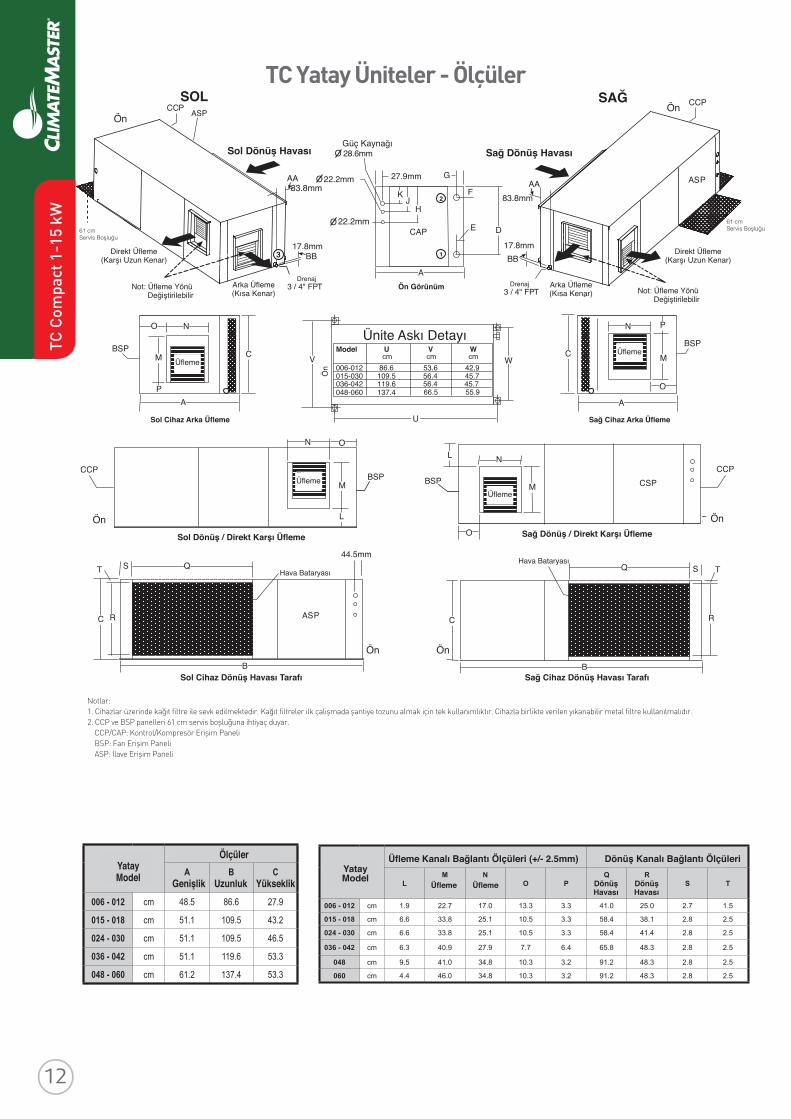
TC Yatay Üniteler - ÖlçülerSOL SAĞ
Sol Dönüş Havası Sağ Dönüş Havası
Ön
Ön Ön
Ön
Ön Görünüm
Direkt Üfleme(Karşı Uzun Kenar)
Direkt Üfleme(Karşı Uzun Kenar)
Not: Üfleme Yönü Değiştirilebilir Not: Üfleme Yönü
Değiştirilebilir
Arka Üfleme(Kısa Kenar)
Güç Kaynağı
22.2mm
83.8mm
Arka Üfleme(Kısa Kenar)
Üfleme
ÜflemeÜfleme
Üfleme
Sol Cihaz Arka Üfleme
Sol Dönüş / Direkt Karşı Üfleme
Sol Cihaz Dönüş Havası Tarafı Sağ Cihaz Dönüş Havası Tarafı
Sağ Dönüş / Direkt Karşı Üfleme
Sağ Cihaz Arka Üfleme
Ön Ön
Notlar:1. Cihazlar üzerinde kağıt filtre ile sevk edilmektedir. Kağıt filtreler ilk çalişmada şantiye tozunu almak için tek kullanımlıktır. Cihazla birlikte verilen yıkanabilir metal filtre kullanılmalıdır.2. CCP ve BSP panelleri 61 cm servis boşluğuna ihtiyaç duyar. CCP/CAP: Kontrol/Kompresör Erişim Paneli BSP: Fan Erişim Paneli ASP: İlave Erişim Paneli
Revised: 8 April, 2016
ClimateMaster works continually to improve its products. As a result, the design and specifi cations of each product at the time of order may be changed without notice and may not be as described herein. Please contact ClimateMaster's Customer Service Department at 1-405-745-6000 for specifi c information on the current design and specifi cations. Statements and other information contained herein are not express warranties and do not form the basis of any bargainbetween the parties, but are merely ClimateMaster's opinion or commendation of its products. The latest version of this document is available at climatemaster.com.
Page ______ of ______LC406 - 21
TC Series 50Hz - HFC410A Submittal Data Eng/S-I
TC - Horizontal - Dimensional Data
HorizontalModel
Overall Cabinet
AWidth
BLength
CHeight
006 - 012 cm 48.5 86.6 27.9
015 - 018 cm 51.1 109.5 43.2
024 - 030 cm 51.1 109.5 46.5
036 - 042 cm 51.1 119.6 53.3
048 - 060 cm 61.2 137.4 53.3
HorizontalModel
Electrical Knockouts
H22.2mm
J22.2mm
K28.6mm
LowVoltage
LowVoltage
PowerSupply
006 - 012 cm 20.6 13.0 5.4
015 - 030 cm 30.8 23.2 15.6
036 - 060 cm 41.0 33.3 25.7
HorizontalModel
Discharge ConnectionDuct Flange Installed (+/- 2.5mm)
Return ConnectionUsing Return Air Opening
LM
SupplyHeight
NSupplyWidth
O PQ
ReturnWidth
RReturnHeight
S T
006 - 012 cm 1.9 22.7 17.0 13.3 3.3 41.0 25.0 2.7 1.5
015 - 018 cm 6.6 33.8 25.1 10.5 3.3 58.4 38.1 2.8 2.5
024 - 030 cm 6.6 33.8 25.1 10.5 3.3 58.4 41.4 2.8 2.5
036 - 042 cm 6.3 40.9 27.9 7.7 6.4 65.8 48.3 2.8 2.5
048 cm 9.5 41.0 34.8 10.3 3.2 91.2 48.3 2.8 2.5
060 cm 4.4 46.0 34.8 10.3 3.2 91.2 48.3 2.8 2.5
HorizontalModel
Water Connections
1 2 3LoopIn/OutFPT
LoopInD
LoopInE
LoopOutF
LoopOutG
Cond. 3/4” FPT
AA BB
006 - 012 cm 24.3 2.7 3.8 2.7 8.4 1.8 1/2”
015 cm 38.4 3.4 8.1 3.5 8.4 1.8 1/2”
018 cm 38.4 3.4 10.4 3.5 8.4 1.8 1/2”
024 cm 41.7 3.4 11.3 3.5 8.4 1.8 3/4”
030 cm 41.7 3.4 7.8 3.5 8.4 1.8 3/4”
036 cm 48.5 3.4 13.4 3.5 8.4 1.8 3/4”
042 cm 48.5 3.4 11.3 3.5 8.4 1.8 3/4”
048 cm 48.5 3.4 11.1 3.5 8.4 1.8 1”
060 cm 48.5 3.4 9.7 3.5 8.4 1.8 1”
YatayModel
Ölçüler
Su Bağlantısı
Genişlik
Giriş Giriş Çıkış Çıkış
LoopGirişÇıkış
Uzunluk Yükseklik
YatayModel
Revised: 8 April, 2016
ClimateMaster works continually to improve its products. As a result, the design and specifi cations of each product at the time of order may be changed without notice and may not be as described herein. Please contact ClimateMaster's Customer Service Department at 1-405-745-6000 for specifi c information on the current design and specifi cations. Statements and other information contained herein are not express warranties and do not form the basis of any bargainbetween the parties, but are merely ClimateMaster's opinion or commendation of its products. The latest version of this document is available at climatemaster.com.
Page ______ of ______LC406 - 21
TC Series 50Hz - HFC410A Submittal Data Eng/S-I
TC - Horizontal - Dimensional Data
HorizontalModel
Overall Cabinet
AWidth
BLength
CHeight
006 - 012 cm 48.5 86.6 27.9
015 - 018 cm 51.1 109.5 43.2
024 - 030 cm 51.1 109.5 46.5
036 - 042 cm 51.1 119.6 53.3
048 - 060 cm 61.2 137.4 53.3
HorizontalModel
Electrical Knockouts
H22.2mm
J22.2mm
K28.6mm
LowVoltage
LowVoltage
PowerSupply
006 - 012 cm 20.6 13.0 5.4
015 - 030 cm 30.8 23.2 15.6
036 - 060 cm 41.0 33.3 25.7
HorizontalModel
Discharge ConnectionDuct Flange Installed (+/- 2.5mm)
Return ConnectionUsing Return Air Opening
LM
SupplyHeight
NSupplyWidth
O PQ
ReturnWidth
RReturnHeight
S T
006 - 012 cm 1.9 22.7 17.0 13.3 3.3 41.0 25.0 2.7 1.5
015 - 018 cm 6.6 33.8 25.1 10.5 3.3 58.4 38.1 2.8 2.5
024 - 030 cm 6.6 33.8 25.1 10.5 3.3 58.4 41.4 2.8 2.5
036 - 042 cm 6.3 40.9 27.9 7.7 6.4 65.8 48.3 2.8 2.5
048 cm 9.5 41.0 34.8 10.3 3.2 91.2 48.3 2.8 2.5
060 cm 4.4 46.0 34.8 10.3 3.2 91.2 48.3 2.8 2.5
HorizontalModel
Water Connections
1 2 3LoopIn/OutFPT
LoopInD
LoopInE
LoopOutF
LoopOutG
Cond. 3/4” FPT
AA BB
006 - 012 cm 24.3 2.7 3.8 2.7 8.4 1.8 1/2”
015 cm 38.4 3.4 8.1 3.5 8.4 1.8 1/2”
018 cm 38.4 3.4 10.4 3.5 8.4 1.8 1/2”
024 cm 41.7 3.4 11.3 3.5 8.4 1.8 3/4”
030 cm 41.7 3.4 7.8 3.5 8.4 1.8 3/4”
036 cm 48.5 3.4 13.4 3.5 8.4 1.8 3/4”
042 cm 48.5 3.4 11.3 3.5 8.4 1.8 3/4”
048 cm 48.5 3.4 11.1 3.5 8.4 1.8 1”
060 cm 48.5 3.4 9.7 3.5 8.4 1.8 1”
YatayModel
Ölçüler
Su Bağlantısı
Üfleme Kanalı Bağlantı Ölçüleri (+/- 2.5mm) Dönüş Kanalı Bağlantı Ölçüleri
Derinlik
Giriş
Üfleme Üfleme DönüşHavası
DönüşHavası
Giriş Çıkış Çıkış
LoopGirişÇıkış
Genişlik Yükseklik
YatayModel
YatayModel
Ünite Askı DetayıÖ
n
DrenajDrenaj
61 cm Servis Boşluğu61 cm
Servis Boşluğu
Hava BataryasıHava Bataryası
TC C
ompa
ct 1
-15
kW
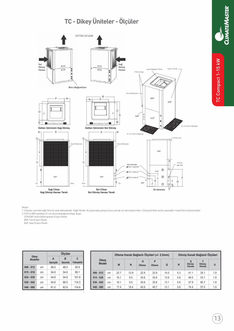
TC - Dikey Üniteler - Ölçüler
Notlar:1. Cihazlar üzerinde kağıt filtre ile sevk edilmektedir. Kağıt filtreler ilk çalişmada şantiye tozunu almak için tek kullanımlıktır. Cihazla birlikte verilen yıkanabilir metal filtre kullanılmalıdır.2. CCP ve BSP panelleri 61 cm servis boşluğuna ihtiyaç duyar. CCP/CAP: Kontrol/Kompresör Erişim Paneli BSP: Fan Erişim Paneli ASP: İlave Erişim Paneli
Revised: 8 April, 2016
ClimateMaster works continually to improve its products. As a result, the design and specifi cations of each product at the time of order may be changed without notice and may not be as described herein. Please contact ClimateMaster's Customer Service Department at 1-405-745-6000 for specifi c information on the current design and specifi cations. Statements and other information contained herein are not express warranties and do not form the basis of any bargainbetween the parties, but are merely ClimateMaster's opinion or commendation of its products. The latest version of this document is available at climatemaster.com.
Page ______ of ______LC406 - 25
TC Series 50Hz - HFC410A Submittal Data Eng/S-I
TC - Vertical Upfl ow - Dimensional Data
VerticalModel
Discharge ConnectionDuct Flange Installed (+/- 2.5mm)
Return ConnectionUsing Return Air Opening
M NO
SupplyWidth
PSupplyDepth
Q RS
ReturnDepth
TReturnHeight
U
006 - 012 cm 22.7 12.9 22.9 22.9 14.0 5.3 41.1 25.1 1.9
015 - 030 cm 16.1 9.5 35.6 35.6 13.6 5.8 46.5 53.1 1.9
036 - 042 cm 16.1 9.5 35.6 35.6 13.1 5.8 57.9 60.7 1.9
048 - 060 cm 17.4 18.4 40.6 45.7 13.1 5.8 74.4 57.0 1.9
Access Panels
Top View-Left Return
U
RS IsometricView
Left Return Left View- Air Coil Opening
T
CPower Supply
3/4" [19.1 mm] HVKnockout
Low Voltage1/2" [12.7 mm] LV
KnockoutLow Voltage
1/2" [12.7 mm] LVKnockout
Condensate3/4" IPT
Front-View
K
1.00 [25.4 mm]
F
J HD
L
Air Coil
Field InstalledDischarge Flange
FrontBack
U
R S
T
C
BackFront
Right Return Right View- Air Coil Opening
BSP
CCP
Filter Rail
ASP
Air Coil
Fron
t
NB
P
AO
M
3
2
1
E
I
G
Top View-Right Return
Front
P N
O
Q
ASP
CCP
ASPASP
ASP
Air Coil
Air Coil Side
BSP
Air Coil Side
Units shipped with filter rails. These rails should be removed for return duct connection. See Aff---- for accessory air filter frame with duct collar.
ÜSTTEN ÜFLEME
SolDönüşHavası
SağDönüşHavası
Boru Bağlantıları
Filtre Kızağı
Hava Bataryası
Hava Bataryası
Güç Kaynağı
Hava Bataryası
Ön Ön
Ön Ö
n
Arka Arka
Kanal Bağlantı Flansı Erişim Paneli
Hava Batarya Tarafı Hava Batarya Tarafı61 cm Servis Boşluğu
61 cm Servis Boşluğu
Drenaj
Sağ CihazSağ Dönüş Havası Tarafı
Üstten Görünüm Sağ Dönüş Üstten Görünüm Sol Dönüş
Sol CihazSol Dönüş Havası Tarafı
Revised: 8 April, 2016
ClimateMaster works continually to improve its products. As a result, the design and specifi cations of each product at the time of order may be changed without notice and may not be as described herein. Please contact ClimateMaster's Customer Service Department at 1-405-745-6000 for specifi c information on the current design and specifi cations. Statements and other information contained herein are not express warranties and do not form the basis of any bargainbetween the parties, but are merely ClimateMaster's opinion or commendation of its products. The latest version of this document is available at climatemaster.com.
Page ______ of ______LC406 - 21
TC Series 50Hz - HFC410A Submittal Data Eng/S-I
TC - Horizontal - Dimensional Data
HorizontalModel
Overall Cabinet
AWidth
BLength
CHeight
006 - 012 cm 48.5 86.6 27.9
015 - 018 cm 51.1 109.5 43.2
024 - 030 cm 51.1 109.5 46.5
036 - 042 cm 51.1 119.6 53.3
048 - 060 cm 61.2 137.4 53.3
HorizontalModel
Electrical Knockouts
H22.2mm
J22.2mm
K28.6mm
LowVoltage
LowVoltage
PowerSupply
006 - 012 cm 20.6 13.0 5.4
015 - 030 cm 30.8 23.2 15.6
036 - 060 cm 41.0 33.3 25.7
HorizontalModel
Discharge ConnectionDuct Flange Installed (+/- 2.5mm)
Return ConnectionUsing Return Air Opening
LM
SupplyHeight
NSupplyWidth
O PQ
ReturnWidth
RReturnHeight
S T
006 - 012 cm 1.9 22.7 17.0 13.3 3.3 41.0 25.0 2.7 1.5
015 - 018 cm 6.6 33.8 25.1 10.5 3.3 58.4 38.1 2.8 2.5
024 - 030 cm 6.6 33.8 25.1 10.5 3.3 58.4 41.4 2.8 2.5
036 - 042 cm 6.3 40.9 27.9 7.7 6.4 65.8 48.3 2.8 2.5
048 cm 9.5 41.0 34.8 10.3 3.2 91.2 48.3 2.8 2.5
060 cm 4.4 46.0 34.8 10.3 3.2 91.2 48.3 2.8 2.5
HorizontalModel
Water Connections
1 2 3LoopIn/OutFPT
LoopInD
LoopInE
LoopOutF
LoopOutG
Cond. 3/4” FPT
AA BB
006 - 012 cm 24.3 2.7 3.8 2.7 8.4 1.8 1/2”
015 cm 38.4 3.4 8.1 3.5 8.4 1.8 1/2”
018 cm 38.4 3.4 10.4 3.5 8.4 1.8 1/2”
024 cm 41.7 3.4 11.3 3.5 8.4 1.8 3/4”
030 cm 41.7 3.4 7.8 3.5 8.4 1.8 3/4”
036 cm 48.5 3.4 13.4 3.5 8.4 1.8 3/4”
042 cm 48.5 3.4 11.3 3.5 8.4 1.8 3/4”
048 cm 48.5 3.4 11.1 3.5 8.4 1.8 1”
060 cm 48.5 3.4 9.7 3.5 8.4 1.8 1”
Revised: 8 April, 2016
ClimateMaster works continually to improve its products. As a result, the design and specifi cations of each product at the time of order may be changed without notice and may not be as described herein. Please contact ClimateMaster's Customer Service Department at 1-405-745-6000 for specifi c information on the current design and specifi cations. Statements and other information contained herein are not express warranties and do not form the basis of any bargainbetween the parties, but are merely ClimateMaster's opinion or commendation of its products. The latest version of this document is available at climatemaster.com.
Page ______ of ______LC406 - 25
TC Series 50Hz - HFC410A Submittal Data Eng/S-I
TC - Vertical Upfl ow - Dimensional Data
VerticalModel
Discharge ConnectionDuct Flange Installed (+/- 2.5mm)
Return ConnectionUsing Return Air Opening
M NO
SupplyWidth
PSupplyDepth
Q RS
ReturnDepth
TReturnHeight
U
006 - 012 cm 22.7 12.9 22.9 22.9 14.0 5.3 41.1 25.1 1.9
015 - 030 cm 16.1 9.5 35.6 35.6 13.6 5.8 46.5 53.1 1.9
036 - 042 cm 16.1 9.5 35.6 35.6 13.1 5.8 57.9 60.7 1.9
048 - 060 cm 17.4 18.4 40.6 45.7 13.1 5.8 74.4 57.0 1.9
Access Panels
Top View-Left Return
U
RS IsometricView
Left Return Left View- Air Coil Opening
T
CPower Supply
3/4" [19.1 mm] HVKnockout
Low Voltage1/2" [12.7 mm] LV
KnockoutLow Voltage
1/2" [12.7 mm] LVKnockout
Condensate3/4" IPT
Front-View
K
1.00 [25.4 mm]
F
J HD
L
Air Coil
Field InstalledDischarge Flange
FrontBack
U
R S
T
C
BackFront
Right Return Right View- Air Coil Opening
BSP
CCP
Filter Rail
ASP
Air Coil
Fron
t
NB
P
AO
M
3
2
1
E
I
G
Top View-Right Return
Front
P N
O
Q
ASP
CCP
ASPASP
ASP
Air Coil
Air Coil Side
BSP
Air Coil Side
Units shipped with filter rails. These rails should be removed for return duct connection. See Aff---- for accessory air filter frame with duct collar.
DikeyModel
Üfleme Kanalı Bağlantı Ölçüleri (+/- 2.5mm) Dönüş Kanalı Bağlantı Ölçüleri
Üfleme Üfleme Dönüş Havası
Dönüş Havası
Ön Görünüm
Revised: 8 April, 2016
ClimateMaster works continually to improve its products. As a result, the design and specifi cations of each product at the time of order may be changed without notice and may not be as described herein. Please contact ClimateMaster's Customer Service Department at 1-405-745-6000 for specifi c information on the current design and specifi cations. Statements and other information contained herein are not express warranties and do not form the basis of any bargainbetween the parties, but are merely ClimateMaster's opinion or commendation of its products. The latest version of this document is available at climatemaster.com.
Page ______ of ______LC406 - 24
TC Series 50Hz - HFC410A Submittal Data Eng/S-I
TC - Vertical Upfl ow - Dimensional Data
Notes:1. While clear access to all removable panels is not required, installer should take care to comply with all building codes and allow adequate clearance for future fi eld service. 2. Front & Side access is preferred for service access. However, all components may be serviced from the front access panel if side access is not available. (Except on TCV 015-030 with front return) Units with front return require left side access for the fan.3. Discharge fl ange is fi eld installed.4. Condensate is 3/4” FPT.5. Units are shipped with an air fi lter supported by a set of fi lter rails. These rails are not suitable for supporting duct work. If a return air duct is to be connected to the unit, these rails should be removed and replaced with the ClimateMaster AFF Series accessory fi lter frame or some other air fi lter support system.
VerticalUpfl owModel
Overall CabinetA
WidthB
DepthC
Height006 - 012 cm 48.5 48.5 55.9
015 - 018 cm 54.6 54.6 99.1
024 - 030 cm 54.6 54.6 101.6
036 - 042 cm 54.6 66.0 114.3
048 - 060 cm 61.0 82.6 116.8
VerticalModel
Electrical KnockoutsJ
22.2mmK
22.2mmL
28.6mmLow
VoltageLow
VoltagePowerSupply
006 - 012 cm 7.3 14.9 22.5
015 - 060 cm 10.5 18.1 5.7
VerticalUpfl owModel
Water Connections - Standard Units1 2 3
LoopIn/
OutFPT
LoopInD
LoopInE
LoopOutF
LoopOutG
Cond. 3/4” FPT
H I
006 - 012 cm 3.6 4.1 24.1 4.3 15.6 4.1 1/2”
015 cm 4.8 3.6 35.1 3.6 20.6 3.6 1/2”
018 cm 4.8 3.6 32.8 3.6 20.6 3.6 1/2”
024 cm 4.8 3.6 35.1 3.6 20.6 3.6 3/4”
030 cm 4.8 3.6 38.6 3.6 20.6 3.6 3/4”
036 cm 4.8 3.6 39.9 3.6 20.6 3.6 3/4”
042 cm 4.8 3.6 42.0 3.6 20.6 3.6 3/4”
048 cm 4.8 3.6 42.2 3.6 20.6 3.6 1”
060 cm 4.8 3.6 43.7 3.6 20.6 3.6 1”
Recommended Minimum Installation Clearances for Vertical Units*
2.5cm
Back of unit
Side opposite return air
15.2cm Front if hard piped
Return Air Side
2.5cm
Ducted return
- ‡ Add for duct width
- † Add 5.0 cm for 2.5 cm fi lter frame/rail or 7.6 cm for 5.0 cm fi lter frame/rail
Free (open) return - calculate required dimension for a maximum velocity of 3.0 m/s
*Field installed accessories (hoses, air cleaners, etc.) may require additional space.Top supply air is shown, the same clearances apply to bottom supply air units.
Air C
oil S
ide
Front
‡ †
2.5cm
15.2cm
2.5cm
2.5cm
Legend:CCP = Control/Compressor Access
PanelBSP = Blower Service Panel ASP = Alternative Service PanelFPT = Female Pipe Thread
Ölçüler Su Bağlantısı
Genişlik Derinlik Yükseklik
DikeyModeller
TC C
ompa
ct 1
-15
kW
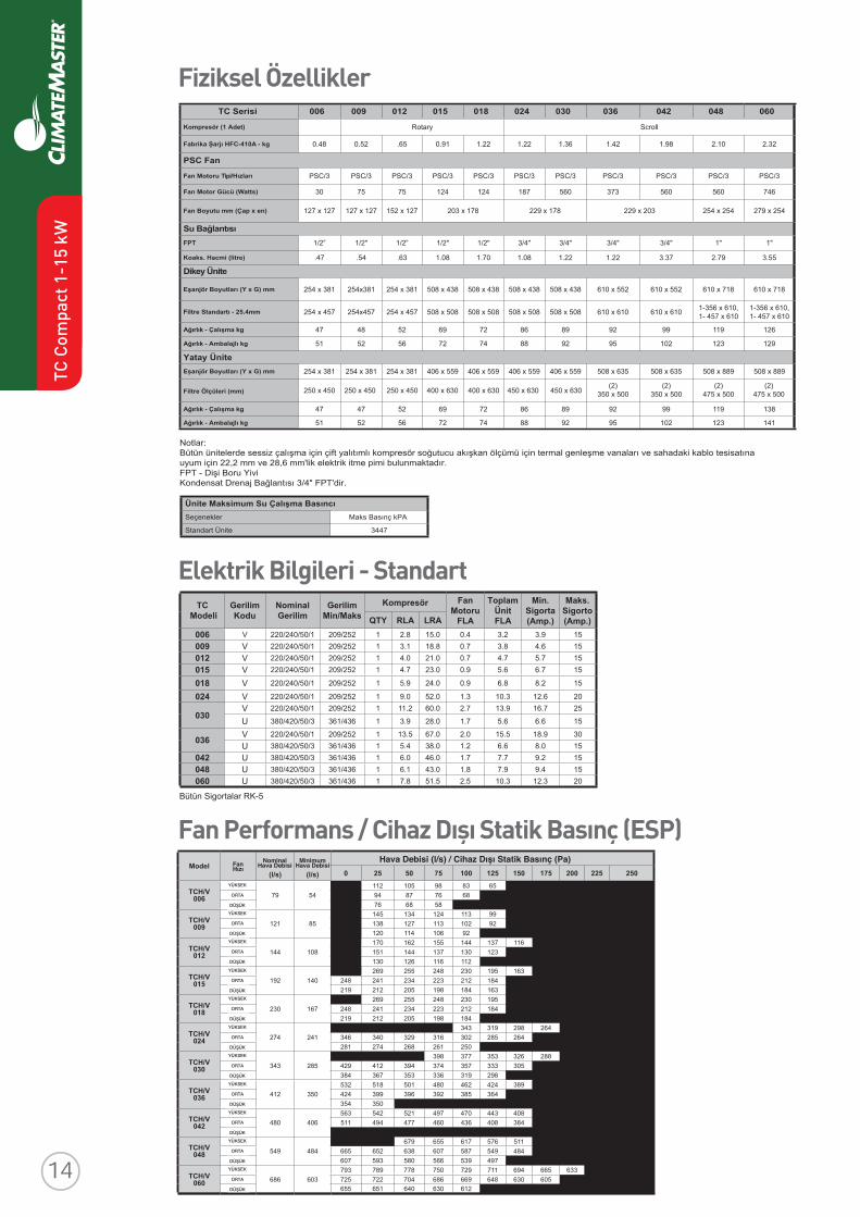
Fiziksel Özellikler
Fan Performans / Cihaz Dışı Statik Basınç (ESP)Model Fan
Speed
RatedAirfl ow
(l/s)
MinAirfl ow
(l/s)
Airfl ow (l/s) at External Static Pressure (Pa.)
0 25 50 75 100 125 150 175 200 225 250
TCH/V006
HI79 54
112 105 98 83 6586677849DEM
858667WOL
TCH/V009
HI121 85
145 134 124 113 9929201311721831DEM
29601411021WOL
TCH/V012
HI144 108
170 162 155 144 137 116321031731441151DEM
211611621031WOL
TCH/V015
HI192 140
0 269 255 248 230 195 163 0 0 0 000000481212322432142842DEM00000361481891502212912WOL
TCH/V018
HI230 167
0 269 255 248 230 195 163 0 0 0 000000481212322432142842DEM00000361481891502212912WOL
TCH/V024
HI274 241
0 0 0 0 343 319 298 264 237 0 000602042462582203613923043643DEM000602322042052162862472182WOL
TCH/V030
HI343 285
0 0 0 398 377 353 326 288 0 0 0000752503333753473493214924DEM0000172892913633353763483WOL
TCH/V036
HI412 350
532 518 501 480 462 424 389 336 0 0 00000923463583293693993424DEM00000623043343743053453WOL
TCH/V042
HI480 406
563 542 521 497 470 443 408 377 0 0 00000483804634064774494115DEM000000463773483883193WOL
TCH/V048
HI549 484
0 0 679 655 617 576 511 439 439 0 00000484945785706836256566DEM0000654794935665085395706WOL
TCH/V060
HI686 603
793 789 778 750 729 711 694 665 633 587 53400375506036846966686407227527DEM000435665195216036046156556WOL
Elektrik Bilgileri - StandartTC
ModeliGerilimKodu
NominalGerilim
GerilimMin/Maks
FanMotoru
ToplamÜnit
Min.Sigorta(Amp.)
Maks.Sigorto(Amp.)
Kompresör
FLA FLAQTY RLA LRA006 V 220/240/50/1 209/252 1 2.8 15.0 0.4 3.2 3.9 15009 V 220/240/50/1 209/252 1 3.1 18.8 0.7 3.8 4.6 15012 V 220/240/50/1 209/252 1 4.0 21.0 0.7 4.7 5.7 15015 V 220/240/50/1 209/252 1 4.7 23.0 0.9 5.6 6.7 15
018 V 220/240/50/1 209/252 1 5.9 24.0 0.9 6.8 8.2 15
024 V 220/240/50/1 209/252 1 9.0 52.0 1.3 10.3 12.6 20
030V 220/240/50/1 209/252 1 11.2 60.0 2.7 13.9 16.7 25
U 380/420/50/3 361/436 1 3.9 28.0 1.7 5.6 6.6 15
036 V 220/240/50/1 209/252 1 13.5 67.0 2.0 15.5 18.9 30U 380/420/50/3 361/436 1 5.4 38.0 1.2 6.6 8.0 15
042 U 380/420/50/3 361/436 1 6.0 46.0 1.7 7.7 9.2 15048 U 380/420/50/3 361/436 1 6.1 43.0 1.8 7.9 9.4 15060 U 380/420/50/3 361/436 1 7.8 51.5 2.5 10.3 12.3 20
Bütün Sigortalar RK-5
Hava Debisi (l/s) / Cihaz Dışı Statik Basınç (Pa)MinimumHava Debisi
NominalHava DebisiFan
Hızı
YÜKSEK
ORTA
DÜŞÜK
YÜKSEK
ORTA
DÜŞÜK
YÜKSEK
ORTA
DÜŞÜK
YÜKSEK
ORTA
DÜŞÜK
YÜKSEK
ORTA
DÜŞÜK
YÜKSEK
ORTA
DÜŞÜK
YÜKSEK
ORTA
DÜŞÜK
YÜKSEK
ORTA
DÜŞÜK
YÜKSEK
ORTA
DÜŞÜK
YÜKSEK
ORTA
DÜŞÜK
YÜKSEK
ORTA
DÜŞÜK
TC Serisi 006 009 012 015 018 024 030 036 042 048 060
Kompresör (1 Adet) llorcSyratoR
Fabrika Şarjı HFC-410A - kg 0.48 0.52 .65 0.91 1.22 1.22 1.36 1.42 1.98 2.10 2.32
PSC Fan
Fan Motoru Tipi/Hızları PSC/3 PSC/3 PSC/3 PSC/3 PSC/3 PSC/3 PSC/3 PSC/3 PSC/3 PSC/3 PSC/3
Fan Motor Gücü (Watts) 30 75 75 124 124 187 560 373 560 560 746
Fan Boyutu mm (Çap x en) 127 x 127 127 x 127 152 x 127 203 x 178 229 x 178 229 x 203 254 x 254 279 x 254
Su BağlantısıFPT 1/2” 1/2" 1/2” 1/2" 1/2" 3/4" 3/4" 3/4" 3/4" 1" 1"
Koaks. Hacmi (litre) .47 .54 .63 1.08 1.70 1.08 1.22 1.22 3.37 2.79 3.55
Dikey Ünite
Eşanjör Boyutları (Y x G) mm 254 x 381 254x381 254 x 381 508 x 438 508 x 438 508 x 438 508 x 438 610 x 552 610 x 552 610 x 718 610 x 718
Filtre Standartı - 25.4mm 254 x 457 254x457 254 x 457 508 x 508 508 x 508 508 x 508 508 x 508 610 x 610 610 x 610 1-356 x 610, 1- 457 x 610
1-356 x 610, 1- 457 x 610
Ağırlık - Çalışma kg 47 48 52 69 72 86 89 92 99 119 126
Ağırlık - Ambalajlı kg 51 52 56 72 74 88 92 95 102 123 129
Yatay ÜniteEşanjör Boyutları (Y x G) mm 254 x 381 254 x 381 254 x 381 406 x 559 406 x 559 406 x 559 406 x 559 508 x 635 508 x 635 508 x 889 508 x 889
Filtre Ölçüleri (mm) 250 x 450 250 x 450 250 x 450 400 x 630 400 x 630 450 x 630 450 x 630(2)
350 x 500(2)
350 x 500(2)
475 x 500(2)
475 x 500
Ağırlık - Çalışma kg 47 47 52 69 72 86 89 92 99 119 138
Ağırlık - Ambalajlı kg 51 52 56 72 74 88 92 95 102 123 141
Notlar:Bütün ünitelerde sessiz çalışma için çift yalıtımlı kompresör soğutucu akışkan ölçümü için termal genleşme vanaları ve sahadaki kablo tesisatına uyum için 22,2 mm ve 28,6 mm'lik elektrik itme pimi bulunmaktadır.FPT - Dişi Boru YiviKondensat Drenaj Bağlantısı 3/4" FPT'dir.
Ünite Maksimum Su Çalışma Basıncı ks Basınç kPA aMSeçenekler
7443 Standart Ünite
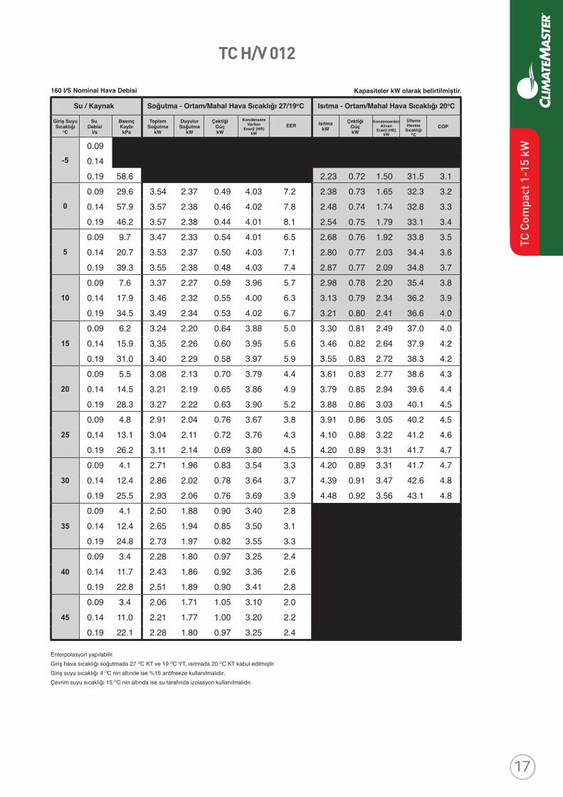
TC C
ompa
ct 1
-15
kW

TC H/V 006
Revised: 8 April, 2016
ClimateMaster works continually to improve its products. As a result, the design and specifi cations of each product at the time of order may be changed without notice and may not be as described herein. Please contact ClimateMaster's Customer Service Department at 1-405-745-6000 for specifi c information on the current design and specifi cations. Statements and other information contained herein are not express warranties and do not form the basis of any bargainbetween the parties, but are merely ClimateMaster's opinion or commendation of its products. The latest version of this document is available at climatemaster.com.
Page ______ of ______LC406 - 6
TC Series 50Hz - HFC410A Submittal Data Eng/S-I
WATER / BRINE COOLING - EAT 27/19 °C HEATING - EAT 20°C
EWT°C
FLOWl/s
PDkPa TC kW SC
kWPower
kW HR kW
EERW/W
HCkW
PowerkW
HEkW LAT COP
W/W
-5Operation not recommended
0
5
10
15
20
25
30
35
Operation not recommended40
45
0.05 0.07 0.09 11.7 1.11 0.36 0.75 31.6 3.10.05 3.4 1.85 1.22 0.25 2.10 7.4 1.19 0.37 0.82 32.4 3.20.07 5.5 1.85 1.19 0.23 2.08 8.0 1.24 0.38 0.86 32.9 3.30.09 9.0 1.84 1.17 0.22 2.06 8.2 1.27 0.38 0.89 33.2 3.40.05 2.8 1.81 1.23 0.28 2.08 6.5 1.34 0.38 0.96 34.0 3.50.07 4.1 1.84 1.22 0.25 2.10 7.3 1.41 0.39 1.02 34.7 3.60.09 6.9 1.85 1.21 0.24 2.10 7.6 1.44 0.39 1.05 35.1 3.70.05 2.1 1.73 1.22 0.30 2.04 5.7 1.50 0.40 1.11 35.7 3.80.07 3.4 1.80 1.23 0.28 2.08 6.4 1.58 0.40 1.18 36.5 3.90.09 6.2 1.82 1.23 0.27 2.09 6.8 1.63 0.41 1.22 37.0 4.00.05 2.1 1.64 1.20 0.34 1.98 4.9 1.67 0.41 1.26 37.4 4.10.07 3.4 1.72 1.22 0.31 2.03 5.6 1.76 0.41 1.34 38.4 4.20.09 5.5 1.75 1.23 0.30 2.05 5.9 1.80 0.42 1.39 38.8 4.30.05 1.4 1.53 1.16 0.37 1.90 4.1 1.83 0.42 1.41 39.1 4.40.07 2.8 1.62 1.19 0.34 1.96 4.7 1.92 0.43 1.49 40.0 4.50.09 4.8 1.66 1.20 0.33 1.99 5.1 1.96 0.43 1.53 40.5 4.60.05 1.4 1.41 1.11 0.40 1.82 3.5 1.97 0.43 1.54 40.6 4.60.07 2.8 1.51 1.15 0.38 1.88 4.0 2.05 0.44 1.61 41.4 4.70.09 4.1 1.55 1.17 0.36 1.91 4.3 2.09 0.44 1.65 41.8 4.70.05 1.4 1.29 1.06 0.44 1.73 2.9 2.09 0.44 1.65 41.8 4.70.07 2.1 1.38 1.10 0.41 1.80 3.3 2.14 0.45 1.69 42.4 4.80.09 4.1 1.43 1.12 0.40 1.83 3.6 2.16 0.45 1.71 42.6 4.80.05 1.4 1.17 1.00 0.48 1.65 2.4 0.07 2.1 1.25 1.04 0.45 1.71 2.8 0.09 4.1 1.30 1.06 0.44 1.74 3.0 0.05 1.4 1.05 0.94 0.52 1.57 2.0 0.07 2.1 1.13 0.98 0.49 1.62 2.3 0.09 3.4 1.17 1.00 0.48 1.65 2.4 0.05 1.4 0.94 0.89 0.56 1.50 1.7 0.07 2.1 1.01 0.92 0.54 1.54 1.9 0.09 3.4 1.04 0.94 0.52 1.57 2.0
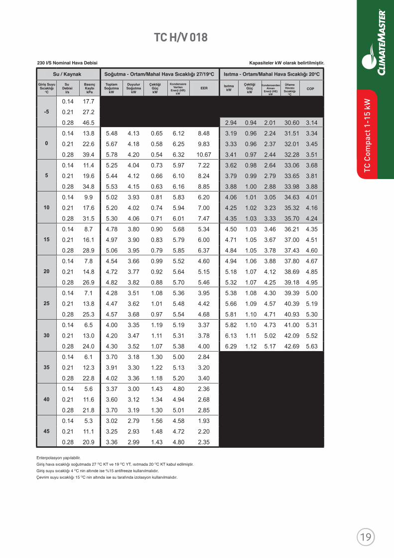
Performance Data - TC H/V 006
79 l/S Nominal Airfl ow Performance capacities shown in kW
Interpolation is permissible; extrapolation is not.All entering air conditions are 27°C DB and 19°C WB in cooling and 20°C DB in heating.AHRI/ISO certifi ed conditions are 27°C DB and 19°C WB in cooling and 20°C DB in heating. Table does not refl ect fan or pump power corrections for AHRI/ISO conditions.All performance data is based upon the lower voltage of dual voltage rated units.Performance stated is at the rated power supply; performance may vary as the power supply varies from the rated.Operation below 4°C EWT is based upon a 15% methanol antifreeze solution.Operation below 16°C EWT requires optional insulated water/refrigerant circuit.See performance correction tables for operating conditions other than those listed above.Gray shaded area refers to calculations required to determine if heating water fl ow is suffi cient for non-antifreeze systems.
79 I/S Nominal Hava Debisi Kapasiteler kW olarak belirtilmiştir.
Soğutma - Ortam/Mahal Hava Sıcaklığı 27/19oCSu / Kaynak Isıtma - Ortam/Mahal Hava Sıcaklığı 20oC
Giriş SuyuSıcaklığı
oC
Su Debisi
l/s
BasınçKaybıkPa
ToplamSoğutma
kW
DuyulurSoğutma
kW
ÇektiğiGüçkW
ÇektiğiGüçkW
ÜflemeHavası
SıcaklığıOC
KondenserdenAlınan
Enerji (HE)kW
COPKondensere
VerilenEnerji (HR)
kW
EER IsıtmakW
Enterpolasyon yapılabilir. Giriş hava sıcaklığı soğutmada 27 OC KT ve 19 OC YT, ısıtmada 20 OC KT kabul edilmiştir.Giriş suyu sıcaklığı 4 OC nin altınde ise %15 antifreeze kullanılmalıdır.Çevrim suyu sıcaklığı 15 OC nin altında ise su tarafında izolasyon kullanılmalıdır.
TC C
ompa
ct 1
-15
kW

TC H/V 009
Revised: 8 April, 2016
ClimateMaster works continually to improve its products. As a result, the design and specifi cations of each product at the time of order may be changed without notice and may not be as described herein. Please contact ClimateMaster's Customer Service Department at 1-405-745-6000 for specifi c information on the current design and specifi cations. Statements and other information contained herein are not express warranties and do not form the basis of any bargainbetween the parties, but are merely ClimateMaster's opinion or commendation of its products. The latest version of this document is available at climatemaster.com.
Page ______ of ______LC406 - 7
TC Series 50Hz - HFC410A Submittal Data Eng/S-I
Performance Data - TC H/V 009
WATER / BRINE COOLING - EAT 27/19 °C HEATING - EAT 20°C
EWT°C
FLOWl/s
PDkPa TC kW SC
kWPower
kW HR kW
EERW/W
HCkW
PowerkW
HEkW LAT COP
W/W
-5Operation not recommended
0
5
10
15
20
25
30
35
Operation not recommended40
45
121 l/S Nominal Airfl ow
Interpolation is permissible; extrapolation is not.All entering air conditions are 27°C DB and 19°C WB in cooling and 20°C DB in heating.AHRI/ISO certifi ed conditions are 27°C DB and 19°C WB in cooling and 20°C DB in heating. Table does not refl ect fan or pump power corrections for AHRI/ISO conditions.All performance data is based upon the lower voltage of dual voltage rated units.Performance stated is at the rated power supply; performance may vary as the power supply varies from the rated.Operation below 4°C EWT is based upon a 15% methanol antifreeze solution.Operation below 16°C EWT requires optional insulated water/refrigerant circuit.See performance correction tables for operating conditions other than those listed above.Gray shaded area refers to calculations required to determine if heating water fl ow is suffi cient for non-antifreeze systems.
0.07 12.9 0.11 17.3 0.14 28.5 1.71 0.54 1.17 31.7 3.20.07 8.2 2.53 1.74 0.34 2.88 7.4 1.82 0.55 1.27 32.5 3.30.11 13.5 2.60 1.73 0.32 2.92 8.2 1.90 0.55 1.35 33.0 3.40.14 23.4 2.63 1.73 0.30 2.93 8.6 1.94 0.56 1.39 33.3 3.50.07 5.8 2.45 1.73 0.38 2.83 6.4 2.04 0.56 1.47 34.0 3.60.11 11.2 2.52 1.74 0.35 2.87 7.2 2.13 0.57 1.56 34.6 3.70.14 20.2 2.55 1.74 0.34 2.89 7.6 2.17 0.57 1.60 34.9 3.80.07 4.4 2.35 1.72 0.42 2.78 5.6 2.25 0.58 1.67 35.4 3.90.11 9.6 2.43 1.73 0.39 2.82 6.2 2.35 0.58 1.77 36.1 4.00.14 18.0 2.46 1.73 0.38 2.84 6.6 2.41 0.59 1.82 36.5 4.10.07 3.5 2.25 1.70 0.47 2.72 4.8 2.46 0.59 1.87 36.9 4.10.11 8.5 2.33 1.72 0.43 2.76 5.4 2.57 0.60 1.97 37.6 4.30.14 16.3 2.37 1.72 0.42 2.79 5.7 2.63 0.61 2.02 38.0 4.30.07 2.9 2.14 1.67 0.52 2.66 4.1 2.67 0.61 2.06 38.3 4.40.11 7.6 2.23 1.70 0.48 2.71 4.6 2.78 0.62 2.16 39.1 4.50.14 15.0 2.27 1.70 0.46 2.73 4.9 2.84 0.63 2.22 39.5 4.50.07 2.4 2.03 1.63 0.57 2.60 3.6 2.87 0.63 2.24 39.7 4.60.11 7.0 2.11 1.66 0.53 2.64 4.0 2.98 0.64 2.34 40.5 4.70.14 13.9 2.15 1.68 0.51 2.67 4.2 3.04 0.65 2.40 40.9 4.70.07 2.1 1.90 1.58 0.63 2.53 3.0 3.05 0.65 2.40 40.9 4.70.11 6.4 1.99 1.62 0.59 2.58 3.4 3.17 0.66 2.51 41.7 4.80.14 13.0 2.03 1.64 0.57 2.60 3.6 3.22 0.67 2.56 42.1 4.80.07 1.8 1.76 1.52 0.68 2.45 2.6 0.11 6.0 1.86 1.57 0.64 2.50 2.9 0.14 12.3 1.90 1.59 0.62 2.53 3.1 0.07 1.6 1.62 1.44 0.74 2.37 2.2 0.11 5.6 1.72 1.50 0.70 2.42 2.4 0.14 11.6 1.76 1.52 0.68 2.45 2.6 0.07 1.4 1.47 1.35 0.81 2.28 1.8 0.11 5.2 1.57 1.41 0.77 2.33 2.0 0.14 11.1 1.62 1.44 0.75 2.36 2.2
Performance capacities shown in kWKapasiteler kW olarak belirtilmiştir.121 I/S Nominal Hava Debisi
Giriş SuyuSıcaklığı
oC
Su Debisi
l/s
BasınçKaybıkPa
ToplamSoğutma
kW
DuyulurSoğutma
kW
ÇektiğiGüçkW
ÇektiğiGüçkW
IsıtmakW
Enterpolasyon yapılabilir. Giriş hava sıcaklığı soğutmada 27 OC KT ve 19 OC YT, ısıtmada 20 OC KT kabul edilmiştir.Giriş suyu sıcaklığı 4 OC nin altınde ise %15 antifreeze kullanılmalıdır.Çevrim suyu sıcaklığı 15 OC nin altında ise su tarafında izolasyon kullanılmalıdır.
Soğutma - Ortam/Mahal Hava Sıcaklığı 27/19oCSu / Kaynak Isıtma - Ortam/Mahal Hava Sıcaklığı 20oC
Revised: 8 April, 2016
ClimateMaster works continually to improve its products. As a result, the design and specifi cations of each product at the time of order may be changed without notice and may not be as described herein. Please contact ClimateMaster's Customer Service Department at 1-405-745-6000 for specifi c information on the current design and specifi cations. Statements and other information contained herein are not express warranties and do not form the basis of any bargainbetween the parties, but are merely ClimateMaster's opinion or commendation of its products. The latest version of this document is available at climatemaster.com.
Page ______ of ______LC406 - 8
TC Series 50Hz - HFC410A Submittal Data Eng/S-I
WATER / BRINE COOLING - EAT 27/19 °C HEATING - EAT 20°C
EWT°C
FLOWl/s
PDkPa TC kW SC
kWPower
kW HR kW
EERW/W
HCkW
PowerkW
HEkW LAT COP
W/W
-5Operation not recommended
0
5
10
15
20
25
30
35
Operation not recommended40
45
0.09 0.14 0.19 58.6 2.23 0.72 1.50 31.5 3.1 0.09 29.6 3.54 2.37 0.49 4.03 7.2 2.38 0.73 1.65 32.3 3.2 0.14 57.9 3.57 2.38 0.46 4.02 7.8 2.48 0.74 1.74 32.8 3.3 0.19 46.2 3.57 2.38 0.44 4.01 8.1 2.54 0.75 1.79 33.1 3.4 0.09 9.7 3.47 2.33 0.54 4.01 6.5 2.68 0.76 1.92 33.8 3.5 0.14 20.7 3.53 2.37 0.50 4.03 7.1 2.80 0.77 2.03 34.4 3.6 0.19 39.3 3.55 2.38 0.48 4.03 7.4 2.87 0.77 2.09 34.8 3.7 0.09 7.6 3.37 2.27 0.59 3.96 5.7 2.98 0.78 2.20 35.4 3.8 0.14 17.9 3.46 2.32 0.55 4.00 6.3 3.13 0.79 2.34 36.2 3.9 0.19 34.5 3.49 2.34 0.53 4.02 6.7 3.21 0.80 2.41 36.6 4.0 0.09 6.2 3.24 2.20 0.64 3.88 5.0 3.30 0.81 2.49 37.0 4.0 0.14 15.9 3.35 2.26 0.60 3.95 5.6 3.46 0.82 2.64 37.9 4.2 0.19 31.0 3.40 2.29 0.58 3.97 5.9 3.55 0.83 2.72 38.3 4.2 0.09 5.5 3.08 2.13 0.70 3.79 4.4 3.61 0.83 2.77 38.6 4.3 0.14 14.5 3.21 2.19 0.65 3.86 4.9 3.79 0.85 2.94 39.6 4.4 0.19 28.3 3.27 2.22 0.63 3.90 5.2 3.88 0.86 3.03 40.1 4.5 0.09 4.8 2.91 2.04 0.76 3.67 3.8 3.91 0.86 3.05 40.2 4.5 0.14 13.1 3.04 2.11 0.72 3.76 4.3 4.10 0.88 3.22 41.2 4.6 0.19 26.2 3.11 2.14 0.69 3.80 4.5 4.20 0.89 3.31 41.7 4.7 0.09 4.1 2.71 1.96 0.83 3.54 3.3 4.20 0.89 3.31 41.7 4.7 0.14 12.4 2.86 2.02 0.78 3.64 3.7 4.39 0.91 3.47 42.6 4.8 0.19 25.5 2.93 2.06 0.76 3.69 3.9 4.48 0.92 3.56 43.1 4.8 0.09 4.1 2.50 1.88 0.90 3.40 2.8 0.14 12.4 2.65 1.94 0.85 3.50 3.1 0.19 24.8 2.73 1.97 0.82 3.55 3.3 0.09 3.4 2.28 1.80 0.97 3.25 2.4 0.14 11.7 2.43 1.86 0.92 3.36 2.6 0.19 22.8 2.51 1.89 0.90 3.41 2.8 0.09 3.4 2.06 1.71 1.05 3.10 2.0 0.14 11.0 2.21 1.77 1.00 3.20 2.2 0.19 22.1 2.28 1.80 0.97 3.25 2.4
Performance Data - TC H/V 012
160 l/S Nominal Airfl ow Performance capacities shown in kW
Interpolation is permissible; extrapolation is not.All entering air conditions are 27°C DB and 19°C WB in cooling and 20°C DB in heating.AHRI/ISO certifi ed conditions are 27°C DB and 19°C WB in cooling and 20°C DB in heating. Table does not refl ect fan or pump power corrections for AHRI/ISO conditions.All performance data is based upon the lower voltage of dual voltage rated units.Performance stated is at the rated power supply; performance may vary as the power supply varies from the rated.Operation below 4°C EWT is based upon a 15% methanol antifreeze solution.Operation below 16°C EWT requires optional insulated water/refrigerant circuit.See performance correction tables for operating conditions other than those listed above.Gray shaded area refers to calculations required to determine if heating water fl ow is suffi cient for non-antifreeze systems.
ÜflemeHavası
SıcaklığıOC
KondenserdenAlınan
Enerji (HE)kW
COPKondensere
VerilenEnerji (HR)
kW
EER
TC C
ompa
ct 1
-15
kW
Revised: 8 April, 2016
ClimateMaster works continually to improve its products. As a result, the design and specifi cations of each product at the time of order may be changed without notice and may not be as described herein. Please contact ClimateMaster's Customer Service Department at 1-405-745-6000 for specifi c information on the current design and specifi cations. Statements and other information contained herein are not express warranties and do not form the basis of any bargainbetween the parties, but are merely ClimateMaster's opinion or commendation of its products. The latest version of this document is available at climatemaster.com.
Page ______ of ______LC406 - 7
TC Series 50Hz - HFC410A Submittal Data Eng/S-I
Performance Data - TC H/V 009
WATER / BRINE COOLING - EAT 27/19 °C HEATING - EAT 20°C
EWT°C
FLOWl/s
PDkPa TC kW SC
kWPower
kW HR kW
EERW/W
HCkW
PowerkW
HEkW LAT COP
W/W
-5Operation not recommended
0
5
10
15
20
25
30
35
Operation not recommended40
45
121 l/S Nominal Airfl ow
Interpolation is permissible; extrapolation is not.All entering air conditions are 27°C DB and 19°C WB in cooling and 20°C DB in heating.AHRI/ISO certifi ed conditions are 27°C DB and 19°C WB in cooling and 20°C DB in heating. Table does not refl ect fan or pump power corrections for AHRI/ISO conditions.All performance data is based upon the lower voltage of dual voltage rated units.Performance stated is at the rated power supply; performance may vary as the power supply varies from the rated.Operation below 4°C EWT is based upon a 15% methanol antifreeze solution.Operation below 16°C EWT requires optional insulated water/refrigerant circuit.See performance correction tables for operating conditions other than those listed above.Gray shaded area refers to calculations required to determine if heating water fl ow is suffi cient for non-antifreeze systems.
0.07 12.9 0.11 17.3 0.14 28.5 1.71 0.54 1.17 31.7 3.20.07 8.2 2.53 1.74 0.34 2.88 7.4 1.82 0.55 1.27 32.5 3.30.11 13.5 2.60 1.73 0.32 2.92 8.2 1.90 0.55 1.35 33.0 3.40.14 23.4 2.63 1.73 0.30 2.93 8.6 1.94 0.56 1.39 33.3 3.50.07 5.8 2.45 1.73 0.38 2.83 6.4 2.04 0.56 1.47 34.0 3.60.11 11.2 2.52 1.74 0.35 2.87 7.2 2.13 0.57 1.56 34.6 3.70.14 20.2 2.55 1.74 0.34 2.89 7.6 2.17 0.57 1.60 34.9 3.80.07 4.4 2.35 1.72 0.42 2.78 5.6 2.25 0.58 1.67 35.4 3.90.11 9.6 2.43 1.73 0.39 2.82 6.2 2.35 0.58 1.77 36.1 4.00.14 18.0 2.46 1.73 0.38 2.84 6.6 2.41 0.59 1.82 36.5 4.10.07 3.5 2.25 1.70 0.47 2.72 4.8 2.46 0.59 1.87 36.9 4.10.11 8.5 2.33 1.72 0.43 2.76 5.4 2.57 0.60 1.97 37.6 4.30.14 16.3 2.37 1.72 0.42 2.79 5.7 2.63 0.61 2.02 38.0 4.30.07 2.9 2.14 1.67 0.52 2.66 4.1 2.67 0.61 2.06 38.3 4.40.11 7.6 2.23 1.70 0.48 2.71 4.6 2.78 0.62 2.16 39.1 4.50.14 15.0 2.27 1.70 0.46 2.73 4.9 2.84 0.63 2.22 39.5 4.50.07 2.4 2.03 1.63 0.57 2.60 3.6 2.87 0.63 2.24 39.7 4.60.11 7.0 2.11 1.66 0.53 2.64 4.0 2.98 0.64 2.34 40.5 4.70.14 13.9 2.15 1.68 0.51 2.67 4.2 3.04 0.65 2.40 40.9 4.70.07 2.1 1.90 1.58 0.63 2.53 3.0 3.05 0.65 2.40 40.9 4.70.11 6.4 1.99 1.62 0.59 2.58 3.4 3.17 0.66 2.51 41.7 4.80.14 13.0 2.03 1.64 0.57 2.60 3.6 3.22 0.67 2.56 42.1 4.80.07 1.8 1.76 1.52 0.68 2.45 2.6 0.11 6.0 1.86 1.57 0.64 2.50 2.9 0.14 12.3 1.90 1.59 0.62 2.53 3.1 0.07 1.6 1.62 1.44 0.74 2.37 2.2 0.11 5.6 1.72 1.50 0.70 2.42 2.4 0.14 11.6 1.76 1.52 0.68 2.45 2.6 0.07 1.4 1.47 1.35 0.81 2.28 1.8 0.11 5.2 1.57 1.41 0.77 2.33 2.0 0.14 11.1 1.62 1.44 0.75 2.36 2.2
Performance capacities shown in kW
TC H/V 012
Revised: 8 April, 2016
ClimateMaster works continually to improve its products. As a result, the design and specifi cations of each product at the time of order may be changed without notice and may not be as described herein. Please contact ClimateMaster's Customer Service Department at 1-405-745-6000 for specifi c information on the current design and specifi cations. Statements and other information contained herein are not express warranties and do not form the basis of any bargainbetween the parties, but are merely ClimateMaster's opinion or commendation of its products. The latest version of this document is available at climatemaster.com.
Page ______ of ______LC406 - 8
TC Series 50Hz - HFC410A Submittal Data Eng/S-I
WATER / BRINE COOLING - EAT 27/19 °C HEATING - EAT 20°C
EWT°C
FLOWl/s
PDkPa TC kW SC
kWPower
kW HR kW
EERW/W
HCkW
PowerkW
HEkW LAT COP
W/W
-5Operation not recommended
0
5
10
15
20
25
30
35
Operation not recommended40
45
0.09 0.14 0.19 58.6 2.23 0.72 1.50 31.5 3.1 0.09 29.6 3.54 2.37 0.49 4.03 7.2 2.38 0.73 1.65 32.3 3.2 0.14 57.9 3.57 2.38 0.46 4.02 7.8 2.48 0.74 1.74 32.8 3.3 0.19 46.2 3.57 2.38 0.44 4.01 8.1 2.54 0.75 1.79 33.1 3.4 0.09 9.7 3.47 2.33 0.54 4.01 6.5 2.68 0.76 1.92 33.8 3.5 0.14 20.7 3.53 2.37 0.50 4.03 7.1 2.80 0.77 2.03 34.4 3.6 0.19 39.3 3.55 2.38 0.48 4.03 7.4 2.87 0.77 2.09 34.8 3.7 0.09 7.6 3.37 2.27 0.59 3.96 5.7 2.98 0.78 2.20 35.4 3.8 0.14 17.9 3.46 2.32 0.55 4.00 6.3 3.13 0.79 2.34 36.2 3.9 0.19 34.5 3.49 2.34 0.53 4.02 6.7 3.21 0.80 2.41 36.6 4.0 0.09 6.2 3.24 2.20 0.64 3.88 5.0 3.30 0.81 2.49 37.0 4.0 0.14 15.9 3.35 2.26 0.60 3.95 5.6 3.46 0.82 2.64 37.9 4.2 0.19 31.0 3.40 2.29 0.58 3.97 5.9 3.55 0.83 2.72 38.3 4.2 0.09 5.5 3.08 2.13 0.70 3.79 4.4 3.61 0.83 2.77 38.6 4.3 0.14 14.5 3.21 2.19 0.65 3.86 4.9 3.79 0.85 2.94 39.6 4.4 0.19 28.3 3.27 2.22 0.63 3.90 5.2 3.88 0.86 3.03 40.1 4.5 0.09 4.8 2.91 2.04 0.76 3.67 3.8 3.91 0.86 3.05 40.2 4.5 0.14 13.1 3.04 2.11 0.72 3.76 4.3 4.10 0.88 3.22 41.2 4.6 0.19 26.2 3.11 2.14 0.69 3.80 4.5 4.20 0.89 3.31 41.7 4.7 0.09 4.1 2.71 1.96 0.83 3.54 3.3 4.20 0.89 3.31 41.7 4.7 0.14 12.4 2.86 2.02 0.78 3.64 3.7 4.39 0.91 3.47 42.6 4.8 0.19 25.5 2.93 2.06 0.76 3.69 3.9 4.48 0.92 3.56 43.1 4.8 0.09 4.1 2.50 1.88 0.90 3.40 2.8 0.14 12.4 2.65 1.94 0.85 3.50 3.1 0.19 24.8 2.73 1.97 0.82 3.55 3.3 0.09 3.4 2.28 1.80 0.97 3.25 2.4 0.14 11.7 2.43 1.86 0.92 3.36 2.6 0.19 22.8 2.51 1.89 0.90 3.41 2.8 0.09 3.4 2.06 1.71 1.05 3.10 2.0 0.14 11.0 2.21 1.77 1.00 3.20 2.2 0.19 22.1 2.28 1.80 0.97 3.25 2.4
Performance Data - TC H/V 012
160 l/S Nominal Airfl ow Performance capacities shown in kW
Interpolation is permissible; extrapolation is not.All entering air conditions are 27°C DB and 19°C WB in cooling and 20°C DB in heating.AHRI/ISO certifi ed conditions are 27°C DB and 19°C WB in cooling and 20°C DB in heating. Table does not refl ect fan or pump power corrections for AHRI/ISO conditions.All performance data is based upon the lower voltage of dual voltage rated units.Performance stated is at the rated power supply; performance may vary as the power supply varies from the rated.Operation below 4°C EWT is based upon a 15% methanol antifreeze solution.Operation below 16°C EWT requires optional insulated water/refrigerant circuit.See performance correction tables for operating conditions other than those listed above.Gray shaded area refers to calculations required to determine if heating water fl ow is suffi cient for non-antifreeze systems.
160 I/S Nominal Hava Debisi
Giriş SuyuSıcaklığı
oC
Su Debisi
l/s
BasınçKaybıkPa
ToplamSoğutma
kW
DuyulurSoğutma
kW
ÇektiğiGüçkW
ÇektiğiGüçkW
IsıtmakW
Enterpolasyon yapılabilir. Giriş hava sıcaklığı soğutmada 27 OC KT ve 19 OC YT, ısıtmada 20 OC KT kabul edilmiştir.Giriş suyu sıcaklığı 4 OC nin altınde ise %15 antifreeze kullanılmalıdır.Çevrim suyu sıcaklığı 15 OC nin altında ise su tarafında izolasyon kullanılmalıdır.
Soğutma - Ortam/Mahal Hava Sıcaklığı 27/19oCSu / Kaynak Isıtma - Ortam/Mahal Hava Sıcaklığı 20oC
Kapasiteler kW olarak belirtilmiştir.
ÜflemeHavası
SıcaklığıOC
KondenserdenAlınan
Enerji (HE)kW
COPKondensere
VerilenEnerji (HR)
kW
EER
TC C
ompa
ct 1
-15
kW
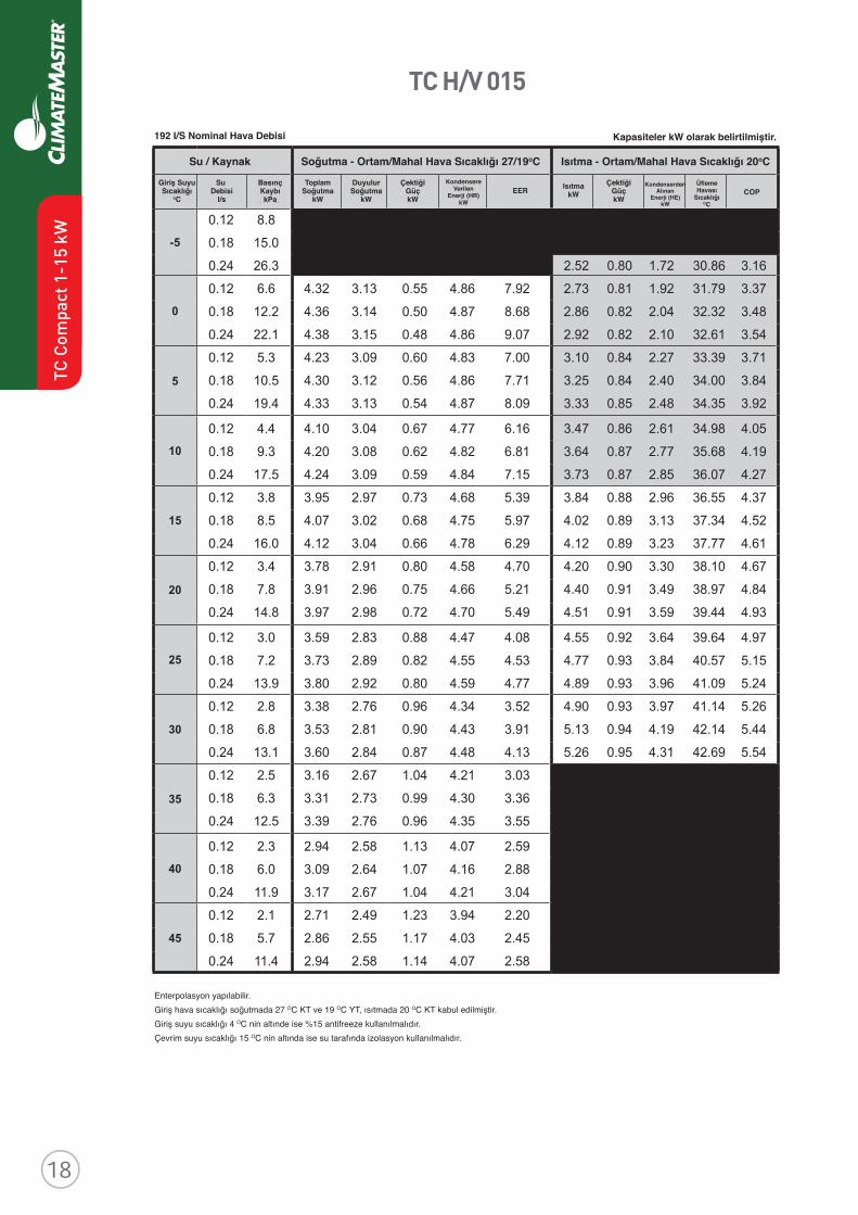
TC H/V 015
Revised: 8 April, 2016
ClimateMaster works continually to improve its products. As a result, the design and specifi cations of each product at the time of order may be changed without notice and may not be as described herein. Please contact ClimateMaster's Customer Service Department at 1-405-745-6000 for specifi c information on the current design and specifi cations. Statements and other information contained herein are not express warranties and do not form the basis of any bargainbetween the parties, but are merely ClimateMaster's opinion or commendation of its products. The latest version of this document is available at climatemaster.com.
Page ______ of ______LC406 - 9
TC Series 50Hz - HFC410A Submittal Data Eng/S-I
Performance Data - TC H/V 015
WATER / BRINE COOLING - EAT 27/19 °C HEATING - EAT 20°C
EWT°C
FLOWl/s
PDkPa TC kW SC
kWPower
kW HR kW
EERW/W
HCkW
PowerkW
HEkW LAT COP
W/W
-5Operation not recommended
0
5
10
15
20
25
30
35
Operation not recommended40
45
192 l/S Nominal Airfl ow
Interpolation is permissible; extrapolation is not.All entering air conditions are 27°C DB and 19°C WB in cooling and 20°C DB in heating.AHRI/ISO certifi ed conditions are 27°C DB and 19°C WB in cooling and 20°C DB in heating. Table does not refl ect fan or pump power corrections for AHRI/ISO conditions.All performance data is based upon the lower voltage of dual voltage rated units.Performance stated is at the rated power supply; performance may vary as the power supply varies from the rated.Operation below 4°C EWT is based upon a 15% methanol antifreeze solution.Operation below 16°C EWT requires optional insulated water/refrigerant circuit.See performance correction tables for operating conditions other than those listed above.Gray shaded area refers to calculations required to determine if heating water fl ow is suffi cient for non-antifreeze systems.
0.12 8.8
0.18 15.0
0.24 26.3 2.52 0.80 1.72 30.86 3.16
0.12 6.6 4.32 3.13 0.55 4.86 7.92 2.73 0.81 1.92 31.79 3.37
0.18 12.2 4.36 3.14 0.50 4.87 8.68 2.86 0.82 2.04 32.32 3.48
0.24 22.1 4.38 3.15 0.48 4.86 9.07 2.92 0.82 2.10 32.61 3.54
0.12 5.3 4.23 3.09 0.60 4.83 7.00 3.10 0.84 2.27 33.39 3.71
0.18 10.5 4.30 3.12 0.56 4.86 7.71 3.25 0.84 2.40 34.00 3.84
0.24 19.4 4.33 3.13 0.54 4.87 8.09 3.33 0.85 2.48 34.35 3.92
0.12 4.4 4.10 3.04 0.67 4.77 6.16 3.47 0.86 2.61 34.98 4.05
0.18 9.3 4.20 3.08 0.62 4.82 6.81 3.64 0.87 2.77 35.68 4.19
0.24 17.5 4.24 3.09 0.59 4.84 7.15 3.73 0.87 2.85 36.07 4.27
0.12 3.8 3.95 2.97 0.73 4.68 5.39 3.84 0.88 2.96 36.55 4.37
0.18 8.5 4.07 3.02 0.68 4.75 5.97 4.02 0.89 3.13 37.34 4.52
0.24 16.0 4.12 3.04 0.66 4.78 6.29 4.12 0.89 3.23 37.77 4.61
0.12 3.4 3.78 2.91 0.80 4.58 4.70 4.20 0.90 3.30 38.10 4.67
0.18 7.8 3.91 2.96 0.75 4.66 5.21 4.40 0.91 3.49 38.97 4.84
0.24 14.8 3.97 2.98 0.72 4.70 5.49 4.51 0.91 3.59 39.44 4.93
0.12 3.0 3.59 2.83 0.88 4.47 4.08 4.55 0.92 3.64 39.64 4.97
0.18 7.2 3.73 2.89 0.82 4.55 4.53 4.77 0.93 3.84 40.57 5.15
0.24 13.9 3.80 2.92 0.80 4.59 4.77 4.89 0.93 3.96 41.09 5.24
0.12 2.8 3.38 2.76 0.96 4.34 3.52 4.90 0.93 3.97 41.14 5.26
0.18 6.8 3.53 2.81 0.90 4.43 3.91 5.13 0.94 4.19 42.14 5.44
0.24 13.1 3.60 2.84 0.87 4.48 4.13 5.26 0.95 4.31 42.69 5.54
0.12 2.5 3.16 2.67 1.04 4.21 3.03
0.18 6.3 3.31 2.73 0.99 4.30 3.36
0.24 12.5 3.39 2.76 0.96 4.35 3.55
0.12 2.3 2.94 2.58 1.13 4.07 2.59
0.18 6.0 3.09 2.64 1.07 4.16 2.88
0.24 11.9 3.17 2.67 1.04 4.21 3.04
0.12 2.1 2.71 2.49 1.23 3.94 2.20
0.18 5.7 2.86 2.55 1.17 4.03 2.45
0.24 11.4 2.94 2.58 1.14 4.07 2.58
Performance capacities shown in kW192 I/S Nominal Hava Debisi
Giriş SuyuSıcaklığı
oC
Su Debisi
l/s
BasınçKaybıkPa
ToplamSoğutma
kW
DuyulurSoğutma
kW
ÇektiğiGüçkW
ÇektiğiGüçkW
IsıtmakW
Enterpolasyon yapılabilir. Giriş hava sıcaklığı soğutmada 27 OC KT ve 19 OC YT, ısıtmada 20 OC KT kabul edilmiştir.Giriş suyu sıcaklığı 4 OC nin altınde ise %15 antifreeze kullanılmalıdır.Çevrim suyu sıcaklığı 15 OC nin altında ise su tarafında izolasyon kullanılmalıdır.
Soğutma - Ortam/Mahal Hava Sıcaklığı 27/19oCSu / Kaynak Isıtma - Ortam/Mahal Hava Sıcaklığı 20oC
Kapasiteler kW olarak belirtilmiştir.
ÜflemeHavası
SıcaklığıOC
KondenserdenAlınan
Enerji (HE)kW
COPKondensere
VerilenEnerji (HR)
kW
EER
TC C
ompa
ct 1
-15
kW
Revised: 8 April, 2016
ClimateMaster works continually to improve its products. As a result, the design and specifi cations of each product at the time of order may be changed without notice and may not be as described herein. Please contact ClimateMaster's Customer Service Department at 1-405-745-6000 for specifi c information on the current design and specifi cations. Statements and other information contained herein are not express warranties and do not form the basis of any bargainbetween the parties, but are merely ClimateMaster's opinion or commendation of its products. The latest version of this document is available at climatemaster.com.
Page ______ of ______LC406 - 9
TC Series 50Hz - HFC410A Submittal Data Eng/S-I
Performance Data - TC H/V 015
WATER / BRINE COOLING - EAT 27/19 °C HEATING - EAT 20°C
EWT°C
FLOWl/s
PDkPa TC kW SC
kWPower
kW HR kW
EERW/W
HCkW
PowerkW
HEkW LAT COP
W/W
-5Operation not recommended
0
5
10
15
20
25
30
35
Operation not recommended40
45
192 l/S Nominal Airfl ow
Interpolation is permissible; extrapolation is not.All entering air conditions are 27°C DB and 19°C WB in cooling and 20°C DB in heating.AHRI/ISO certifi ed conditions are 27°C DB and 19°C WB in cooling and 20°C DB in heating. Table does not refl ect fan or pump power corrections for AHRI/ISO conditions.All performance data is based upon the lower voltage of dual voltage rated units.Performance stated is at the rated power supply; performance may vary as the power supply varies from the rated.Operation below 4°C EWT is based upon a 15% methanol antifreeze solution.Operation below 16°C EWT requires optional insulated water/refrigerant circuit.See performance correction tables for operating conditions other than those listed above.Gray shaded area refers to calculations required to determine if heating water fl ow is suffi cient for non-antifreeze systems.
0.12 8.8
0.18 15.0
0.24 26.3 2.52 0.80 1.72 30.86 3.16
0.12 6.6 4.32 3.13 0.55 4.86 7.92 2.73 0.81 1.92 31.79 3.37
0.18 12.2 4.36 3.14 0.50 4.87 8.68 2.86 0.82 2.04 32.32 3.48
0.24 22.1 4.38 3.15 0.48 4.86 9.07 2.92 0.82 2.10 32.61 3.54
0.12 5.3 4.23 3.09 0.60 4.83 7.00 3.10 0.84 2.27 33.39 3.71
0.18 10.5 4.30 3.12 0.56 4.86 7.71 3.25 0.84 2.40 34.00 3.84
0.24 19.4 4.33 3.13 0.54 4.87 8.09 3.33 0.85 2.48 34.35 3.92
0.12 4.4 4.10 3.04 0.67 4.77 6.16 3.47 0.86 2.61 34.98 4.05
0.18 9.3 4.20 3.08 0.62 4.82 6.81 3.64 0.87 2.77 35.68 4.19
0.24 17.5 4.24 3.09 0.59 4.84 7.15 3.73 0.87 2.85 36.07 4.27
0.12 3.8 3.95 2.97 0.73 4.68 5.39 3.84 0.88 2.96 36.55 4.37
0.18 8.5 4.07 3.02 0.68 4.75 5.97 4.02 0.89 3.13 37.34 4.52
0.24 16.0 4.12 3.04 0.66 4.78 6.29 4.12 0.89 3.23 37.77 4.61
0.12 3.4 3.78 2.91 0.80 4.58 4.70 4.20 0.90 3.30 38.10 4.67
0.18 7.8 3.91 2.96 0.75 4.66 5.21 4.40 0.91 3.49 38.97 4.84
0.24 14.8 3.97 2.98 0.72 4.70 5.49 4.51 0.91 3.59 39.44 4.93
0.12 3.0 3.59 2.83 0.88 4.47 4.08 4.55 0.92 3.64 39.64 4.97
0.18 7.2 3.73 2.89 0.82 4.55 4.53 4.77 0.93 3.84 40.57 5.15
0.24 13.9 3.80 2.92 0.80 4.59 4.77 4.89 0.93 3.96 41.09 5.24
0.12 2.8 3.38 2.76 0.96 4.34 3.52 4.90 0.93 3.97 41.14 5.26
0.18 6.8 3.53 2.81 0.90 4.43 3.91 5.13 0.94 4.19 42.14 5.44
0.24 13.1 3.60 2.84 0.87 4.48 4.13 5.26 0.95 4.31 42.69 5.54
0.12 2.5 3.16 2.67 1.04 4.21 3.03
0.18 6.3 3.31 2.73 0.99 4.30 3.36
0.24 12.5 3.39 2.76 0.96 4.35 3.55
0.12 2.3 2.94 2.58 1.13 4.07 2.59
0.18 6.0 3.09 2.64 1.07 4.16 2.88
0.24 11.9 3.17 2.67 1.04 4.21 3.04
0.12 2.1 2.71 2.49 1.23 3.94 2.20
0.18 5.7 2.86 2.55 1.17 4.03 2.45
0.24 11.4 2.94 2.58 1.14 4.07 2.58
Performance capacities shown in kW
TC C
ompa
ct 1
-15
kW
TC H/V 018
Revised: 8 April, 2016
ClimateMaster works continually to improve its products. As a result, the design and specifi cations of each product at the time of order may be changed without notice and may not be as described herein. Please contact ClimateMaster's Customer Service Department at 1-405-745-6000 for specifi c information on the current design and specifi cations. Statements and other information contained herein are not express warranties and do not form the basis of any bargainbetween the parties, but are merely ClimateMaster's opinion or commendation of its products. The latest version of this document is available at climatemaster.com.
Page ______ of ______LC406 - 10
TC Series 50Hz - HFC410A Submittal Data Eng/S-I
WATER / BRINE COOLING - EAT 27/19 °C HEATING - EAT 20°C
EWT°C
FLOWl/s
PDkPa TC kW SC
kWPower
kW HR kW
EERW/W
HCkW
PowerkW
HEkW LAT COP
W/W
-5Operation not recommended
0
5
10
15
20
25
30
35
Operation not recommended40
45
Performance capacities shown in kW
0.14 17.7
0.21 27.2
0.28 46.5 2.94 0.94 2.01 30.60 3.14
0.14 13.8 5.48 4.13 0.65 6.12 8.48 3.19 0.96 2.24 31.51 3.34
0.21 22.6 5.67 4.18 0.58 6.25 9.83 3.33 0.96 2.37 32.01 3.45
0.28 39.4 5.78 4.20 0.54 6.32 10.67 3.41 0.97 2.44 32.28 3.51
0.14 11.4 5.25 4.04 0.73 5.97 7.22 3.62 0.98 2.64 33.06 3.68
0.21 19.6 5.44 4.12 0.66 6.10 8.24 3.79 0.99 2.79 33.65 3.81
0.28 34.8 5.53 4.15 0.63 6.16 8.85 3.88 1.00 2.88 33.98 3.88
0.14 9.9 5.02 3.93 0.81 5.83 6.20 4.06 1.01 3.05 34.63 4.01
0.21 17.6 5.20 4.02 0.74 5.94 7.00 4.25 1.02 3.23 35.32 4.16
0.28 31.5 5.30 4.06 0.71 6.01 7.47 4.35 1.03 3.33 35.70 4.24
0.14 8.7 4.78 3.80 0.90 5.68 5.34 4.50 1.03 3.46 36.21 4.35
0.21 16.1 4.97 3.90 0.83 5.79 6.00 4.71 1.05 3.67 37.00 4.51
0.28 28.9 5.06 3.95 0.79 5.85 6.37 4.84 1.05 3.78 37.43 4.60
0.14 7.8 4.54 3.66 0.99 5.52 4.60 4.94 1.06 3.88 37.80 4.67
0.21 14.8 4.72 3.77 0.92 5.64 5.15 5.18 1.07 4.12 38.69 4.85
0.28 26.9 4.82 3.82 0.88 5.70 5.46 5.32 1.07 4.25 39.18 4.95
0.14 7.1 4.28 3.51 1.08 5.36 3.95 5.38 1.08 4.30 39.39 5.00
0.21 13.8 4.47 3.62 1.01 5.48 4.42 5.66 1.09 4.57 40.39 5.19
0.28 25.3 4.57 3.68 0.97 5.54 4.68 5.81 1.10 4.71 40.93 5.30
0.14 6.5 4.00 3.35 1.19 5.19 3.37 5.82 1.10 4.73 41.00 5.31
0.21 13.0 4.20 3.47 1.11 5.31 3.78 6.13 1.11 5.02 42.09 5.52
0.28 24.0 4.30 3.52 1.07 5.38 4.00 6.29 1.12 5.17 42.69 5.63
0.14 6.1 3.70 3.18 1.30 5.00 2.84
0.21 12.3 3.91 3.30 1.22 5.13 3.20
0.28 22.8 4.02 3.36 1.18 5.20 3.40
0.14 5.6 3.37 3.00 1.43 4.80 2.36
0.21 11.6 3.60 3.12 1.34 4.94 2.68
0.28 21.8 3.70 3.19 1.30 5.01 2.85
0.14 5.3 3.02 2.79 1.56 4.58 1.93
0.21 11.1 3.25 2.93 1.48 4.72 2.20
0.28 20.9 3.36 2.99 1.43 4.80 2.35
Performance Data - TC H/V 018
230 l/S Nominal Airfl ow
Interpolation is permissible; extrapolation is not.All entering air conditions are 27°C DB and 19°C WB in cooling and 20°C DB in heating.AHRI/ISO certifi ed conditions are 27°C DB and 19°C WB in cooling and 20°C DB in heating. Table does not refl ect fan or pump power corrections for AHRI/ISO conditions.All performance data is based upon the lower voltage of dual voltage rated units.Performance stated is at the rated power supply; performance may vary as the power supply varies from the rated.Operation below 4°C EWT is based upon a 15% methanol antifreeze solution.Operation below 16°C EWT requires optional insulated water/refrigerant circuit.See performance correction tables for operating conditions other than those listed above.Gray shaded area refers to calculations required to determine if heating water fl ow is suffi cient for non-antifreeze systems.
230 I/S Nominal Hava Debisi
Giriş SuyuSıcaklığı
oC
Su Debisi
l/s
BasınçKaybıkPa
ToplamSoğutma
kW
DuyulurSoğutma
kW
ÇektiğiGüçkW
ÇektiğiGüçkW
IsıtmakW
Enterpolasyon yapılabilir. Giriş hava sıcaklığı soğutmada 27 OC KT ve 19 OC YT, ısıtmada 20 OC KT kabul edilmiştir.Giriş suyu sıcaklığı 4 OC nin altınde ise %15 antifreeze kullanılmalıdır.Çevrim suyu sıcaklığı 15 OC nin altında ise su tarafında izolasyon kullanılmalıdır.
ÜflemeHavası
SıcaklığıOC
KondenserdenAlınan
Enerji (HE)kW
COPKondensere
VerilenEnerji (HR)
kW
EER
Soğutma - Ortam/Mahal Hava Sıcaklığı 27/19oCSu / Kaynak Isıtma - Ortam/Mahal Hava Sıcaklığı 20oC
Kapasiteler kW olarak belirtilmiştir.

TC H/V 024
Revised: 8 April, 2016
ClimateMaster works continually to improve its products. As a result, the design and specifi cations of each product at the time of order may be changed without notice and may not be as described herein. Please contact ClimateMaster's Customer Service Department at 1-405-745-6000 for specifi c information on the current design and specifi cations. Statements and other information contained herein are not express warranties and do not form the basis of any bargainbetween the parties, but are merely ClimateMaster's opinion or commendation of its products. The latest version of this document is available at climatemaster.com.
Page ______ of ______LC406 - 11
TC Series 50Hz - HFC410A Submittal Data Eng/S-I
Performance Data - TC H/V 024
WATER / BRINE COOLING - EAT 27/19 °C HEATING - EAT 20°C
EWT°C
FLOWl/s
PDkPa TC kW SC
kWPower
kW HR kW
EERW/W
HCkW
PowerkW
HEkW LAT COP
W/W
-5Operation not recommended
0
5
10
15
20
25
30
35
Operation not recommended40
45
274 l/S Nominal Airfl ow
Interpolation is permissible; extrapolation is not.All entering air conditions are 27°C DB and 19°C WB in cooling and 20°C DB in heating.AHRI/ISO certifi ed conditions are 27°C DB and 19°C WB in cooling and 20°C DB in heating. Table does not refl ect fan or pump power corrections for AHRI/ISO conditions.All performance data is based upon the lower voltage of dual voltage rated units.Performance stated is at the rated power supply; performance may vary as the power supply varies from the rated.Operation below 4°C EWT is based upon a 15% methanol antifreeze solution.Operation below 16°C EWT requires optional insulated water/refrigerant circuit.See performance correction tables for operating conditions other than those listed above.Gray shaded area refers to calculations required to determine if heating water fl ow is suffi cient for non-antifreeze systems.
0.19 17.9 0.28 31.1 0.38 55.4 4.18 1.34 2.84 32.63 3.12 0.19 14.9 7.23 5.48 0.95 8.18 7.57 4.54 1.47 3.07 33.71 3.09 0.28 26.9 7.36 5.53 0.89 8.26 8.23 4.74 1.48 3.26 34.32 3.21 0.38 48.5 7.43 5.54 0.87 8.29 8.56 4.85 1.48 3.37 34.65 3.27 0.19 13.0 7.03 5.41 1.04 8.07 6.76 5.16 1.50 3.66 35.58 3.44 0.28 24.2 7.19 5.47 0.97 8.16 7.41 5.40 1.51 3.89 36.31 3.57 0.38 44.0 7.26 5.50 0.94 8.20 7.74 5.53 1.52 4.01 36.72 3.64 0.19 11.6 6.81 5.31 1.14 7.95 5.97 5.78 1.53 4.25 37.48 3.78 0.28 22.2 6.99 5.39 1.06 8.05 6.59 6.06 1.55 4.52 38.32 3.92 0.38 40.6 7.07 5.42 1.02 8.09 6.91 6.22 1.56 4.66 38.79 4.00
0.19 10.6 6.57 5.20 1.26 7.82 5.22 6.40 1.57 4.84 39.35 4.09 0.28 20.7 6.76 5.29 1.17 7.92 5.80 6.72 1.58 5.13 40.30 4.24 0.38 38.0 6.85 5.33 1.12 7.97 6.10 6.88 1.59 5.29 40.80 4.32
0.19 9.8 6.30 5.08 1.39 7.69 4.53 7.01 1.60 5.41 41.18 4.38 0.28 19.4 6.51 5.17 1.29 7.79 5.06 7.34 1.62 5.72 42.18 4.53 0.38 35.9 6.61 5.22 1.24 7.84 5.34 7.52 1.63 5.88 42.71 4.61 0.19 9.2 6.02 4.95 1.55 7.56 3.89 7.58 1.64 5.95 42.92 4.64 0.28 18.4 6.23 5.05 1.43 7.66 4.36 7.92 1.66 6.26 43.93 4.78 0.38 34.1 6.34 5.09 1.37 7.71 4.62 8.09 1.67 6.42 44.45 4.85
0.19 8.6 5.71 4.82 1.72 7.43 3.31 8.11 1.67 6.44 44.52 4.86 0.28 17.5 5.94 4.92 1.59 7.53 3.74 8.44 1.69 6.74 45.49 4.98 0.38 32.7 6.05 4.96 1.53 7.58 3.96 8.60 1.70 6.89 45.97 5.04 0.19 8.1 5.39 4.69 1.92 7.31 2.80 0.28 16.8 5.63 4.79 1.78 7.40 3.17 0.38 31.3 5.74 4.83 1.70 7.45 3.37 0.19 7.7 5.05 4.56 2.15 7.20 2.35 0.28 16.1 5.30 4.66 1.98 7.28 2.67 0.38 30.2 5.42 4.70 1.91 7.32 2.84 0.19 7.4 4.70 4.43 2.41 7.10 1.95 0.28 15.6 4.95 4.53 2.22 7.17 2.23 0.38 29.3 5.08 4.57 2.13 7.21 2.38
Performance capacities shown in kW274 I/S Nominal Hava Debisi
Giriş SuyuSıcaklığı
oC
Su Debisi
l/s
BasınçKaybıkPa
ToplamSoğutma
kW
DuyulurSoğutma
kW
ÇektiğiGüçkW
ÇektiğiGüçkW
IsıtmakW
Enterpolasyon yapılabilir. Giriş hava sıcaklığı soğutmada 27 OC KT ve 19 OC YT, ısıtmada 20 OC KT kabul edilmiştir.Giriş suyu sıcaklığı 4 OC nin altınde ise %15 antifreeze kullanılmalıdır.Çevrim suyu sıcaklığı 15 OC nin altında ise su tarafında izolasyon kullanılmalıdır.
ÜflemeHavası
SıcaklığıOC
KondenserdenAlınan
Enerji (HE)kW
COPKondensere
VerilenEnerji (HR)
kW
EER
Soğutma - Ortam/Mahal Hava Sıcaklığı 27/19oCSu / Kaynak Isıtma - Ortam/Mahal Hava Sıcaklığı 20oC
Kapasiteler kW olarak belirtilmiştir.
TC C
ompa
ct 1
-15
kW
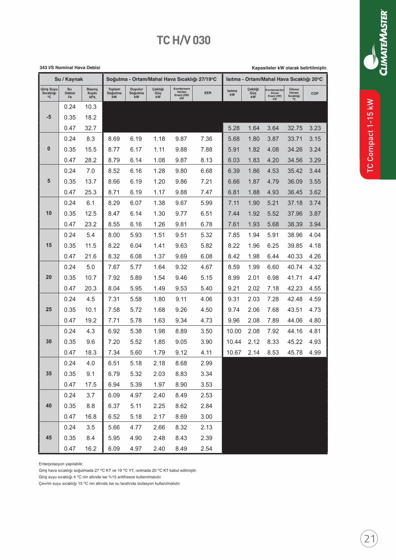
Revised: 8 April, 2016
ClimateMaster works continually to improve its products. As a result, the design and specifi cations of each product at the time of order may be changed without notice and may not be as described herein. Please contact ClimateMaster's Customer Service Department at 1-405-745-6000 for specifi c information on the current design and specifi cations. Statements and other information contained herein are not express warranties and do not form the basis of any bargainbetween the parties, but are merely ClimateMaster's opinion or commendation of its products. The latest version of this document is available at climatemaster.com.
Page ______ of ______LC406 - 11
TC Series 50Hz - HFC410A Submittal Data Eng/S-I
Performance Data - TC H/V 024
WATER / BRINE COOLING - EAT 27/19 °C HEATING - EAT 20°C
EWT°C
FLOWl/s
PDkPa TC kW SC
kWPower
kW HR kW
EERW/W
HCkW
PowerkW
HEkW LAT COP
W/W
-5Operation not recommended
0
5
10
15
20
25
30
35
Operation not recommended40
45
274 l/S Nominal Airfl ow
Interpolation is permissible; extrapolation is not.All entering air conditions are 27°C DB and 19°C WB in cooling and 20°C DB in heating.AHRI/ISO certifi ed conditions are 27°C DB and 19°C WB in cooling and 20°C DB in heating. Table does not refl ect fan or pump power corrections for AHRI/ISO conditions.All performance data is based upon the lower voltage of dual voltage rated units.Performance stated is at the rated power supply; performance may vary as the power supply varies from the rated.Operation below 4°C EWT is based upon a 15% methanol antifreeze solution.Operation below 16°C EWT requires optional insulated water/refrigerant circuit.See performance correction tables for operating conditions other than those listed above.Gray shaded area refers to calculations required to determine if heating water fl ow is suffi cient for non-antifreeze systems.
0.19 17.9 0.28 31.1 0.38 55.4 4.18 1.34 2.84 32.63 3.12 0.19 14.9 7.23 5.48 0.95 8.18 7.57 4.54 1.47 3.07 33.71 3.09 0.28 26.9 7.36 5.53 0.89 8.26 8.23 4.74 1.48 3.26 34.32 3.21 0.38 48.5 7.43 5.54 0.87 8.29 8.56 4.85 1.48 3.37 34.65 3.27 0.19 13.0 7.03 5.41 1.04 8.07 6.76 5.16 1.50 3.66 35.58 3.44 0.28 24.2 7.19 5.47 0.97 8.16 7.41 5.40 1.51 3.89 36.31 3.57 0.38 44.0 7.26 5.50 0.94 8.20 7.74 5.53 1.52 4.01 36.72 3.64 0.19 11.6 6.81 5.31 1.14 7.95 5.97 5.78 1.53 4.25 37.48 3.78 0.28 22.2 6.99 5.39 1.06 8.05 6.59 6.06 1.55 4.52 38.32 3.92 0.38 40.6 7.07 5.42 1.02 8.09 6.91 6.22 1.56 4.66 38.79 4.00
0.19 10.6 6.57 5.20 1.26 7.82 5.22 6.40 1.57 4.84 39.35 4.09 0.28 20.7 6.76 5.29 1.17 7.92 5.80 6.72 1.58 5.13 40.30 4.24 0.38 38.0 6.85 5.33 1.12 7.97 6.10 6.88 1.59 5.29 40.80 4.32
0.19 9.8 6.30 5.08 1.39 7.69 4.53 7.01 1.60 5.41 41.18 4.38 0.28 19.4 6.51 5.17 1.29 7.79 5.06 7.34 1.62 5.72 42.18 4.53 0.38 35.9 6.61 5.22 1.24 7.84 5.34 7.52 1.63 5.88 42.71 4.61 0.19 9.2 6.02 4.95 1.55 7.56 3.89 7.58 1.64 5.95 42.92 4.64 0.28 18.4 6.23 5.05 1.43 7.66 4.36 7.92 1.66 6.26 43.93 4.78 0.38 34.1 6.34 5.09 1.37 7.71 4.62 8.09 1.67 6.42 44.45 4.85
0.19 8.6 5.71 4.82 1.72 7.43 3.31 8.11 1.67 6.44 44.52 4.86 0.28 17.5 5.94 4.92 1.59 7.53 3.74 8.44 1.69 6.74 45.49 4.98 0.38 32.7 6.05 4.96 1.53 7.58 3.96 8.60 1.70 6.89 45.97 5.04 0.19 8.1 5.39 4.69 1.92 7.31 2.80 0.28 16.8 5.63 4.79 1.78 7.40 3.17 0.38 31.3 5.74 4.83 1.70 7.45 3.37 0.19 7.7 5.05 4.56 2.15 7.20 2.35 0.28 16.1 5.30 4.66 1.98 7.28 2.67 0.38 30.2 5.42 4.70 1.91 7.32 2.84 0.19 7.4 4.70 4.43 2.41 7.10 1.95 0.28 15.6 4.95 4.53 2.22 7.17 2.23 0.38 29.3 5.08 4.57 2.13 7.21 2.38
Performance capacities shown in kW
TC H/V 030
Revised: 8 April, 2016
ClimateMaster works continually to improve its products. As a result, the design and specifi cations of each product at the time of order may be changed without notice and may not be as described herein. Please contact ClimateMaster's Customer Service Department at 1-405-745-6000 for specifi c information on the current design and specifi cations. Statements and other information contained herein are not express warranties and do not form the basis of any bargainbetween the parties, but are merely ClimateMaster's opinion or commendation of its products. The latest version of this document is available at climatemaster.com.
Page ______ of ______LC406 - 12
TC Series 50Hz - HFC410A Submittal Data Eng/S-I
Performance Data - TC H/V 030
WATER / BRINE COOLING - EAT 27/19 °C HEATING - EAT 20°C
EWT°C
FLOWl/s
PDkPa TC kW SC
kWPower
kW HR kW
EERW/W
HCkW
PowerkW
HEkW LAT COP
W/W
-5Operation not recommended
0
5
10
15
20
25
30
35
Operation not recommended40
45
343 l/S Nominal Airfl ow
Interpolation is permissible; extrapolation is not.All entering air conditions are 27°C DB and 19°C WB in cooling and 20°C DB in heating.AHRI/ISO certifi ed conditions are 27°C DB and 19°C WB in cooling and 20°C DB in heating. Table does not refl ect fan or pump power corrections for AHRI/ISO conditions.All performance data is based upon the lower voltage of dual voltage rated units.Performance stated is at the rated power supply; performance may vary as the power supply varies from the rated.Operation below 4°C EWT is based upon a 15% methanol antifreeze solution.Operation below 16°C EWT requires optional insulated water/refrigerant circuit.See performance correction tables for operating conditions other than those listed above.Gray shaded area refers to calculations required to determine if heating water fl ow is suffi cient for non-antifreeze systems.
0.24 10.3
0.35 18.2
0.47 32.7 5.28 1.64 3.64 32.75 3.23
0.24 8.3 8.69 6.19 1.18 9.87 7.36 5.68 1.80 3.87 33.71 3.15
0.35 15.5 8.77 6.17 1.11 9.88 7.88 5.91 1.82 4.08 34.26 3.24
0.47 28.2 8.79 6.14 1.08 9.87 8.13 6.03 1.83 4.20 34.56 3.29
0.24 7.0 8.52 6.16 1.28 9.80 6.68 6.39 1.86 4.53 35.42 3.44
0.35 13.7 8.66 6.19 1.20 9.86 7.21 6.66 1.87 4.79 36.09 3.55
0.47 25.3 8.71 6.19 1.17 9.88 7.47 6.81 1.88 4.93 36.45 3.62
0.24 6.1 8.29 6.07 1.38 9.67 5.99 7.11 1.90 5.21 37.18 3.74
0.35 12.5 8.47 6.14 1.30 9.77 6.51 7.44 1.92 5.52 37.96 3.87
0.47 23.2 8.55 6.16 1.26 9.81 6.78 7.61 1.93 5.68 38.39 3.94
0.24 5.4 8.00 5.93 1.51 9.51 5.32 7.85 1.94 5.91 38.96 4.04
0.35 11.5 8.22 6.04 1.41 9.63 5.82 8.22 1.96 6.25 39.85 4.18
0.47 21.6 8.32 6.08 1.37 9.69 6.08 8.42 1.98 6.44 40.33 4.26
0.24 5.0 7.67 5.77 1.64 9.32 4.67 8.59 1.99 6.60 40.74 4.32
0.35 10.7 7.92 5.89 1.54 9.46 5.15 8.99 2.01 6.98 41.71 4.47
0.47 20.3 8.04 5.95 1.49 9.53 5.40 9.21 2.02 7.18 42.23 4.55
0.24 4.5 7.31 5.58 1.80 9.11 4.06 9.31 2.03 7.28 42.48 4.59
0.35 10.1 7.58 5.72 1.68 9.26 4.50 9.74 2.06 7.68 43.51 4.73
0.47 19.2 7.71 5.78 1.63 9.34 4.73 9.96 2.08 7.89 44.06 4.80
0.24 4.3 6.92 5.38 1.98 8.89 3.50 10.00 2.08 7.92 44.16 4.81
0.35 9.6 7.20 5.52 1.85 9.05 3.90 10.44 2.12 8.33 45.22 4.93
0.47 18.3 7.34 5.60 1.79 9.12 4.11 10.67 2.14 8.53 45.78 4.99
0.24 4.0 6.51 5.18 2.18 8.68 2.99
0.35 9.1 6.79 5.32 2.03 8.83 3.34
0.47 17.5 6.94 5.39 1.97 8.90 3.53
0.24 3.7 6.09 4.97 2.40 8.49 2.53
0.35 8.8 6.37 5.11 2.25 8.62 2.84
0.47 16.8 6.52 5.18 2.17 8.69 3.00
0.24 3.5 5.66 4.77 2.66 8.32 2.13
0.35 8.4 5.95 4.90 2.48 8.43 2.39
0.47 16.2 6.09 4.97 2.40 8.49 2.54
Performance capacities shown in kW343 I/S Nominal Hava Debisi
Giriş SuyuSıcaklığı
oC
Su Debisi
l/s
BasınçKaybıkPa
ToplamSoğutma
kW
DuyulurSoğutma
kW
ÇektiğiGüçkW
ÇektiğiGüçkW
IsıtmakW
Enterpolasyon yapılabilir. Giriş hava sıcaklığı soğutmada 27 OC KT ve 19 OC YT, ısıtmada 20 OC KT kabul edilmiştir.Giriş suyu sıcaklığı 4 OC nin altınde ise %15 antifreeze kullanılmalıdır.Çevrim suyu sıcaklığı 15 OC nin altında ise su tarafında izolasyon kullanılmalıdır.
ÜflemeHavası
SıcaklığıOC
KondenserdenAlınan
Enerji (HE)kW
COPKondensere
VerilenEnerji (HR)
kW
EER
Soğutma - Ortam/Mahal Hava Sıcaklığı 27/19oCSu / Kaynak Isıtma - Ortam/Mahal Hava Sıcaklığı 20oC
Kapasiteler kW olarak belirtilmiştir.
TC C
ompa
ct 1
-15
kW

TC H/V 036
Revised: 8 April, 2016
ClimateMaster works continually to improve its products. As a result, the design and specifi cations of each product at the time of order may be changed without notice and may not be as described herein. Please contact ClimateMaster's Customer Service Department at 1-405-745-6000 for specifi c information on the current design and specifi cations. Statements and other information contained herein are not express warranties and do not form the basis of any bargainbetween the parties, but are merely ClimateMaster's opinion or commendation of its products. The latest version of this document is available at climatemaster.com.
Page ______ of ______LC406 - 13
TC Series 50Hz - HFC410A Submittal Data Eng/S-I
Performance Data - TC H/V 036
WATER / BRINE COOLING - EAT 27/19 °C HEATING - EAT 20°C
EWT°C
FLOWl/s
PDkPa TC kW SC
kWPower
kW HR kW
EERW/W
HCkW
PowerkW
HEkW LAT COP
W/W
-5Operation not recommended
0
5
10
15
20
25
30
35
Operation not recommended40
45
412 l/S Nominal Airfl ow
Interpolation is permissible; extrapolation is not.All entering air conditions are 27°C DB and 19°C WB in cooling and 20°C DB in heating.AHRI/ISO certifi ed conditions are 27°C DB and 19°C WB in cooling and 20°C DB in heating. Table does not refl ect fan or pump power corrections for AHRI/ISO conditions.All performance data is based upon the lower voltage of dual voltage rated units.Performance stated is at the rated power supply; performance may vary as the power supply varies from the rated.Operation below 4°C EWT is based upon a 15% methanol antifreeze solution.Operation below 16°C EWT requires optional insulated water/refrigerant circuit.See performance correction tables for operating conditions other than those listed above.Gray shaded area refers to calculations required to determine if heating water fl ow is suffi cient for non-antifreeze systems.
0.28 14.7
0.43 23.9
0.57 41.6 6.16 1.91 4.25 32.38 3.23
0.28 12.3 10.43 7.39 1.42 11.85 7.34 6.76 2.14 4.63 33.60 3.16
0.43 20.6 10.49 7.42 1.37 11.86 7.67 7.10 2.18 4.92 34.28 3.26
0.57 36.2 10.49 7.42 1.35 11.85 7.76 7.29 2.20 5.08 34.65 3.31
0.28 10.7 10.24 7.32 1.52 11.76 6.73 7.80 2.26 5.53 35.68 3.44
0.43 18.4 10.39 7.38 1.44 11.83 7.21 8.20 2.31 5.89 36.49 3.55
0.57 32.6 10.45 7.40 1.41 11.85 7.42 8.42 2.34 6.08 36.93 3.60
0.28 9.6 9.95 7.21 1.66 11.61 6.01 8.82 2.38 6.44 37.74 3.70
0.43 16.8 10.18 7.29 1.55 11.73 6.56 9.28 2.44 6.85 38.67 3.81
0.57 30.0 10.27 7.33 1.50 11.78 6.83 9.54 2.46 7.07 39.18 3.87
0.28 8.7 9.58 7.07 1.82 11.40 5.26 9.83 2.50 7.34 39.77 3.94
0.43 15.6 9.87 7.18 1.69 11.56 5.82 10.34 2.55 7.79 40.79 4.05
0.57 28.0 9.99 7.22 1.64 11.63 6.11 10.61 2.58 8.03 41.34 4.11
0.28 8.1 9.15 6.91 2.02 11.17 4.54 10.81 2.60 8.21 41.73 4.16
0.43 14.6 9.48 7.03 1.87 11.35 5.07 11.35 2.66 8.69 42.82 4.27
0.57 26.4 9.63 7.09 1.80 11.43 5.35 11.63 2.68 8.95 43.39 4.33
0.28 7.5 8.68 6.73 2.24 10.92 3.88 11.73 2.69 9.04 43.59 4.36
0.43 13.8 9.03 6.86 2.08 11.10 4.35 12.28 2.75 9.53 44.70 4.47
0.57 25.0 9.20 6.93 2.00 11.20 4.61 12.57 2.77 9.79 45.27 4.53
0.28 7.0 8.18 6.53 2.48 10.66 3.29 12.59 2.78 9.81 45.32 4.53
0.43 13.2 8.54 6.67 2.31 10.84 3.70 13.13 2.83 10.30 46.40 4.64
0.57 23.9 8.72 6.74 2.22 10.94 3.93 13.39 2.85 10.54 46.94 4.70
0.28 6.7 7.66 6.32 2.75 10.41 2.78
0.43 12.5 8.02 6.47 2.56 10.58 3.13
0.57 22.9 8.20 6.54 2.47 10.67 3.32
0.28 6.3 7.13 6.11 3.04 10.18 2.34
0.43 12.1 7.49 6.25 2.84 10.33 2.63
0.57 22.0 7.67 6.33 2.75 10.42 2.79
0.28 6.1 6.63 5.89 3.36 9.98 1.97
0.43 11.6 6.96 6.03 3.15 10.11 2.21
0.57 21.3 7.14 6.11 3.04 10.18 2.35
Performance capacities shown in kW412 I/S Nominal Hava Debisi
Giriş SuyuSıcaklığı
oC
Su Debisi
l/s
BasınçKaybıkPa
ToplamSoğutma
kW
DuyulurSoğutma
kW
ÇektiğiGüçkW
ÇektiğiGüçkW
IsıtmakW
Enterpolasyon yapılabilir. Giriş hava sıcaklığı soğutmada 27 OC KT ve 19 OC YT, ısıtmada 20 OC KT kabul edilmiştir.Giriş suyu sıcaklığı 4 OC nin altınde ise %15 antifreeze kullanılmalıdır.Çevrim suyu sıcaklığı 15 OC nin altında ise su tarafında izolasyon kullanılmalıdır.
ÜflemeHavası
SıcaklığıOC
KondenserdenAlınan
Enerji (HE)kW
COPKondensere
VerilenEnerji (HR)
kW
EER
Soğutma - Ortam/Mahal Hava Sıcaklığı 27/19oCSu / Kaynak Isıtma - Ortam/Mahal Hava Sıcaklığı 20oC
Kapasiteler kW olarak belirtilmiştir.
TC C
ompa
ct 1
-15
kW
8.97
9.26
9.35
8.54
8.73
8.82
8.00
8.40
8.70
7.50
7.95
8.10
6.64
6.96
7.15
6.93
7.06
7.34
6.67
6.83
6.95
6.50
6.62
6.49
6.32
6.47
6.54
5.89
6.03
6.11
2.14
2.04
2.02
2.14
2.12
2.10
2.26
2.20
2.17
2.70
2.64
2.52
2.83
2.64
2.58
11.11
11.20
11.37
10.68
10.85
10.92
10.26
10.60
10.87
10.20
10.59
10.62
9.47
9.60
9.73
4.19
4.49
4.61
3.99
4.10
4.20
3.53
3.81
3.96
2.77
3.01
3.21
2.34
2.63
2.77

Revised: 8 April, 2016
ClimateMaster works continually to improve its products. As a result, the design and specifi cations of each product at the time of order may be changed without notice and may not be as described herein. Please contact ClimateMaster's Customer Service Department at 1-405-745-6000 for specifi c information on the current design and specifi cations. Statements and other information contained herein are not express warranties and do not form the basis of any bargainbetween the parties, but are merely ClimateMaster's opinion or commendation of its products. The latest version of this document is available at climatemaster.com.
Page ______ of ______LC406 - 13
TC Series 50Hz - HFC410A Submittal Data Eng/S-I
Performance Data - TC H/V 036
WATER / BRINE COOLING - EAT 27/19 °C HEATING - EAT 20°C
EWT°C
FLOWl/s
PDkPa TC kW SC
kWPower
kW HR kW
EERW/W
HCkW
PowerkW
HEkW LAT COP
W/W
-5Operation not recommended
0
5
10
15
20
25
30
35
Operation not recommended40
45
412 l/S Nominal Airfl ow
Interpolation is permissible; extrapolation is not.All entering air conditions are 27°C DB and 19°C WB in cooling and 20°C DB in heating.AHRI/ISO certifi ed conditions are 27°C DB and 19°C WB in cooling and 20°C DB in heating. Table does not refl ect fan or pump power corrections for AHRI/ISO conditions.All performance data is based upon the lower voltage of dual voltage rated units.Performance stated is at the rated power supply; performance may vary as the power supply varies from the rated.Operation below 4°C EWT is based upon a 15% methanol antifreeze solution.Operation below 16°C EWT requires optional insulated water/refrigerant circuit.See performance correction tables for operating conditions other than those listed above.Gray shaded area refers to calculations required to determine if heating water fl ow is suffi cient for non-antifreeze systems.
0.28 14.7
0.43 23.9
0.57 41.6 6.16 1.91 4.25 32.38 3.23
0.28 12.3 10.43 7.39 1.42 11.85 7.34 6.76 2.14 4.63 33.60 3.16
0.43 20.6 10.49 7.42 1.37 11.86 7.67 7.10 2.18 4.92 34.28 3.26
0.57 36.2 10.49 7.42 1.35 11.85 7.76 7.29 2.20 5.08 34.65 3.31
0.28 10.7 10.24 7.32 1.52 11.76 6.73 7.80 2.26 5.53 35.68 3.44
0.43 18.4 10.39 7.38 1.44 11.83 7.21 8.20 2.31 5.89 36.49 3.55
0.57 32.6 10.45 7.40 1.41 11.85 7.42 8.42 2.34 6.08 36.93 3.60
0.28 9.6 9.95 7.21 1.66 11.61 6.01 8.82 2.38 6.44 37.74 3.70
0.43 16.8 10.18 7.29 1.55 11.73 6.56 9.28 2.44 6.85 38.67 3.81
0.57 30.0 10.27 7.33 1.50 11.78 6.83 9.54 2.46 7.07 39.18 3.87
0.28 8.7 9.58 7.07 1.82 11.40 5.26 9.83 2.50 7.34 39.77 3.94
0.43 15.6 9.87 7.18 1.69 11.56 5.82 10.34 2.55 7.79 40.79 4.05
0.57 28.0 9.99 7.22 1.64 11.63 6.11 10.61 2.58 8.03 41.34 4.11
0.28 8.1 9.15 6.91 2.02 11.17 4.54 10.81 2.60 8.21 41.73 4.16
0.43 14.6 9.48 7.03 1.87 11.35 5.07 11.35 2.66 8.69 42.82 4.27
0.57 26.4 9.63 7.09 1.80 11.43 5.35 11.63 2.68 8.95 43.39 4.33
0.28 7.5 8.68 6.73 2.24 10.92 3.88 11.73 2.69 9.04 43.59 4.36
0.43 13.8 9.03 6.86 2.08 11.10 4.35 12.28 2.75 9.53 44.70 4.47
0.57 25.0 9.20 6.93 2.00 11.20 4.61 12.57 2.77 9.79 45.27 4.53
0.28 7.0 8.18 6.53 2.48 10.66 3.29 12.59 2.78 9.81 45.32 4.53
0.43 13.2 8.54 6.67 2.31 10.84 3.70 13.13 2.83 10.30 46.40 4.64
0.57 23.9 8.72 6.74 2.22 10.94 3.93 13.39 2.85 10.54 46.94 4.70
0.28 6.7 7.66 6.32 2.75 10.41 2.78
0.43 12.5 8.02 6.47 2.56 10.58 3.13
0.57 22.9 8.20 6.54 2.47 10.67 3.32
0.28 6.3 7.13 6.11 3.04 10.18 2.34
0.43 12.1 7.49 6.25 2.84 10.33 2.63
0.57 22.0 7.67 6.33 2.75 10.42 2.79
0.28 6.1 6.63 5.89 3.36 9.98 1.97
0.43 11.6 6.96 6.03 3.15 10.11 2.21
0.57 21.3 7.14 6.11 3.04 10.18 2.35
Performance capacities shown in kW
TC H/V 042
Revised: 8 April, 2016
ClimateMaster works continually to improve its products. As a result, the design and specifi cations of each product at the time of order may be changed without notice and may not be as described herein. Please contact ClimateMaster's Customer Service Department at 1-405-745-6000 for specifi c information on the current design and specifi cations. Statements and other information contained herein are not express warranties and do not form the basis of any bargainbetween the parties, but are merely ClimateMaster's opinion or commendation of its products. The latest version of this document is available at climatemaster.com.
Page ______ of ______LC406 - 14
TC Series 50Hz - HFC410A Submittal Data Eng/S-I
Performance Data - TC H/V 042
WATER / BRINE COOLING - EAT 27/19 °C HEATING - EAT 20°C
EWT°C
FLOWl/s
PDkPa TC kW SC
kWPower
kW HR kW
EERW/W
HCkW
PowerkW
HEkW LAT COP
W/W
-5Operation not recommended
0
5
10
15
20
25
30
35
Operation not recommended40
45
480 l/S Nominal Airfl ow
Interpolation is permissible; extrapolation is not.All entering air conditions are 27°C DB and 19°C WB in cooling and 20°C DB in heating.AHRI/ISO certifi ed conditions are 27°C DB and 19°C WB in cooling and 20°C DB in heating. Table does not refl ect fan or pump power corrections for AHRI/ISO conditions.All performance data is based upon the lower voltage of dual voltage rated units.Performance stated is at the rated power supply; performance may vary as the power supply varies from the rated.Operation below 4°C EWT is based upon a 15% methanol antifreeze solution.Operation below 16°C EWT requires optional insulated water/refrigerant circuit.See performance correction tables for operating conditions other than those listed above.Gray shaded area refers to calculations required to determine if heating water fl ow is suffi cient for non-antifreeze systems.
0.33 18.1 0.50 33.2 0.66 60.1 7.73 2.38 5.35 33.35 3.25 0.33 15.2 12.34 9.31 1.60 13.93 7.73 8.30 2.63 5.68 34.33 3.16 0.50 29.0 12.61 9.45 1.50 14.11 8.39 8.66 2.66 6.00 34.94 3.26 0.66 53.1 12.74 9.53 1.46 14.20 8.73 8.85 2.68 6.18 35.28 3.31 0.33 13.4 11.99 9.12 1.73 13.72 6.92 9.35 2.72 6.63 36.15 3.44 0.50 26.3 12.26 9.27 1.62 13.88 7.55 9.78 2.76 7.02 36.88 3.54 0.66 48.3 12.40 9.34 1.57 13.97 7.88 10.02 2.78 7.24 37.29 3.60 0.33 12.1 11.63 8.92 1.89 13.52 6.14 10.43 2.82 7.61 38.01 3.70 0.50 24.2 11.90 9.07 1.77 13.67 6.73 10.93 2.87 8.07 38.88 3.81 0.66 44.8 12.04 9.15 1.71 13.75 7.04 11.21 2.89 8.32 39.35 3.88
0.33 11.2 11.24 8.73 2.08 13.33 5.40 11.53 2.92 8.60 39.90 3.95 0.50 22.7 11.53 8.88 1.94 13.47 5.95 12.09 2.97 9.12 40.88 4.07 0.66 42.1 11.68 8.95 1.87 13.55 6.24 12.40 3.00 9.40 41.41 4.13 0.33 10.3 10.84 8.55 2.30 13.14 4.72 12.62 3.02 9.59 41.78 4.17 0.50 21.4 11.14 8.68 2.13 13.28 5.22 13.24 3.08 10.16 42.86 4.30 0.66 39.9 11.29 8.76 2.06 13.35 5.49 13.58 3.11 10.47 43.44 4.36
0.33 9.7 10.41 8.37 2.54 12.95 4.10 13.69 3.12 10.57 43.64 4.38 0.50 20.3 10.73 8.50 2.36 13.09 4.55 14.36 3.18 11.17 44.79 4.51 0.66 38.0 10.88 8.57 2.27 13.16 4.79 14.71 3.22 11.50 45.40 4.57 0.33 9.2 9.95 8.20 2.81 12.76 3.54 14.73 3.22 11.51 45.43 4.58 0.50 19.4 10.28 8.32 2.61 12.90 3.94 15.42 3.28 12.14 46.63 4.70 0.66 36.5 10.45 8.39 2.51 12.96 4.16 15.79 3.32 12.47 47.25 4.76 0.33 8.8 9.45 8.03 3.12 12.56 3.03 0.50 18.7 9.81 8.15 2.89 12.70 3.39 0.66 35.1 9.98 8.21 2.79 12.77 3.58
0.33 8.3 8.90 7.85 3.46 12.36 2.58 0.50 18.0 9.29 7.98 3.21 12.50 2.89 0.66 34.0 9.48 8.04 3.10 12.57 3.06 0.33 8.0 8.32 7.66 3.83 12.15 2.17 0.50 17.4 8.73 7.80 3.57 12.30 2.45 0.66 32.9 8.93 7.86 3.44 12.37 2.60
Performance capacities shown in kW480 I/S Nominal Hava Debisi
Giriş SuyuSıcaklığı
oC
Su Debisi
l/s
BasınçKaybıkPa
ToplamSoğutma
kW
DuyulurSoğutma
kW
ÇektiğiGüçkW
ÇektiğiGüçkW
IsıtmakW
Enterpolasyon yapılabilir. Giriş hava sıcaklığı soğutmada 27 OC KT ve 19 OC YT, ısıtmada 20 OC KT kabul edilmiştir.Giriş suyu sıcaklığı 4 OC nin altınde ise %15 antifreeze kullanılmalıdır.Çevrim suyu sıcaklığı 15 OC nin altında ise su tarafında izolasyon kullanılmalıdır.
ÜflemeHavası
SıcaklığıOC
KondenserdenAlınan
Enerji (HE)kW
COPKondensere
VerilenEnerji (HR)
kW
EER
Soğutma - Ortam/Mahal Hava Sıcaklığı 27/19oCSu / Kaynak Isıtma - Ortam/Mahal Hava Sıcaklığı 20oC
Kapasiteler kW olarak belirtilmiştir.
TC C
ompa
ct 1
-15
kW

TC H/V 048
Revised: 8 April, 2016
ClimateMaster works continually to improve its products. As a result, the design and specifi cations of each product at the time of order may be changed without notice and may not be as described herein. Please contact ClimateMaster's Customer Service Department at 1-405-745-6000 for specifi c information on the current design and specifi cations. Statements and other information contained herein are not express warranties and do not form the basis of any bargainbetween the parties, but are merely ClimateMaster's opinion or commendation of its products. The latest version of this document is available at climatemaster.com.
Page ______ of ______LC406 - 15
TC Series 50Hz - HFC410A Submittal Data Eng/S-I
Performance Data - TC H/V 048
WATER / BRINE COOLING - EAT 27/19 °C HEATING - EAT 20°C
EWT°C
FLOWl/s
PDkPa TC kW SC
kWPower
kW HR kW
EERW/W
HCkW
PowerkW
HEkW LAT COP
W/W
-5Operation not recommended
0
5
10
15
20
25
30
35
Operation not recommended40
45
549 l/S Nominal Airfl ow
Interpolation is permissible; extrapolation is not.All entering air conditions are 27°C DB and 19°C WB in cooling and 20°C DB in heating.AHRI/ISO certifi ed conditions are 27°C DB and 19°C WB in cooling and 20°C DB in heating. Table does not refl ect fan or pump power corrections for AHRI/ISO conditions.All performance data is based upon the lower voltage of dual voltage rated units.Performance stated is at the rated power supply; performance may vary as the power supply varies from the rated.Operation below 4°C EWT is based upon a 15% methanol antifreeze solution.Operation below 16°C EWT requires optional insulated water/refrigerant circuit.See performance correction tables for operating conditions other than those listed above.Gray shaded area refers to calculations required to determine if heating water fl ow is suffi cient for non-antifreeze systems.
0.38 13.4 0.57 24.9 0.76 45.1 8.11 2.49 5.62 32.25 3.25 0.38 11.9 14.70 10.49 1.92 16.62 7.65 8.72 2.73 5.99 33.16 3.19 0.57 22.9 14.98 10.54 1.80 16.78 8.31 9.05 2.76 6.30 33.67 3.29 0.76 41.9 15.11 10.55 1.75 16.85 8.64 9.24 2.77 6.47 33.95 3.34 0.38 10.9 14.31 10.36 2.09 16.40 6.85 9.81 2.80 7.01 34.81 3.50 0.57 21.5 14.63 10.47 1.95 16.58 7.50 10.23 2.83 7.41 35.45 3.62 0.76 39.6 14.78 10.51 1.89 16.67 7.83 10.47 2.84 7.63 35.80 3.68 0.38 10.1 13.86 10.18 2.28 16.14 6.07 10.97 2.87 8.10 36.57 3.82 0.57 20.4 14.22 10.33 2.12 16.35 6.69 11.49 2.90 8.58 37.34 3.96 0.76 37.9 14.40 10.39 2.05 16.45 7.02 11.77 2.92 8.85 37.76 4.03
0.38 9.6 13.35 9.95 2.51 15.86 5.32 12.18 2.94 9.24 38.39 4.14 0.57 19.6 13.76 10.13 2.33 16.08 5.91 12.77 2.98 9.79 39.28 4.29 0.76 36.5 13.95 10.21 2.24 16.19 6.22 13.10 3.00 10.10 39.78 4.37 0.38 9.1 12.80 9.69 2.77 15.56 4.62 13.40 3.02 10.38 40.23 4.44 0.57 18.9 13.23 9.89 2.56 15.80 5.16 14.07 3.06 11.01 41.25 4.60 0.76 35.3 13.44 9.99 2.47 15.91 5.45 14.44 3.09 11.35 41.80 4.68
0.38 8.7 12.19 9.40 3.07 15.25 3.98 14.62 3.10 11.53 42.08 4.72 0.57 18.3 12.66 9.62 2.84 15.49 4.46 15.35 3.15 12.21 43.18 4.88 0.76 34.4 12.88 9.73 2.73 15.61 4.72 15.74 3.18 12.57 43.77 4.96 0.38 8.4 11.53 9.10 3.40 14.94 3.39 15.82 3.18 12.64 43.88 4.97 0.57 17.8 12.03 9.33 3.15 15.17 3.82 16.58 3.24 13.35 45.04 5.12 0.76 33.5 12.27 9.44 3.03 15.29 4.06 16.99 3.27 13.72 45.64 5.19 0.38 8.1 10.83 8.78 3.79 14.62 2.86 0.57 17.4 11.35 9.01 3.50 14.85 3.24 0.76 32.7 11.60 9.13 3.37 14.97 3.45
0.38 7.9 10.08 8.44 4.22 14.30 2.39 0.57 16.9 10.62 8.69 3.90 14.53 2.72 0.76 32.1 10.89 8.81 3.75 14.64 2.90 0.38 7.6 9.29 8.09 4.70 13.99 1.98 0.57 16.6 9.85 8.34 4.35 14.21 2.26 0.76 31.5 10.13 8.47 4.19 14.32 2.42
Performance capacities shown in kW549 I/S Nominal Hava Debisi
Giriş SuyuSıcaklığı
oC
Su Debisi
l/s
BasınçKaybıkPa
ToplamSoğutma
kW
DuyulurSoğutma
kW
ÇektiğiGüçkW
ÇektiğiGüçkW
IsıtmakW
Enterpolasyon yapılabilir. Giriş hava sıcaklığı soğutmada 27 OC KT ve 19 OC YT, ısıtmada 20 OC KT kabul edilmiştir.Giriş suyu sıcaklığı 4 OC nin altınde ise %15 antifreeze kullanılmalıdır.Çevrim suyu sıcaklığı 15 OC nin altında ise su tarafında izolasyon kullanılmalıdır.
ÜflemeHavası
SıcaklığıOC
KondenserdenAlınan
Enerji (HE)kW
COPKondensere
VerilenEnerji (HR)
kW
EER
Soğutma - Ortam/Mahal Hava Sıcaklığı 27/19oCSu / Kaynak Isıtma - Ortam/Mahal Hava Sıcaklığı 20oC
Kapasiteler kW olarak belirtilmiştir.
TC C
ompa
ct 1
-15
kW
12.25
12.75
12.90
11.90
12.15
12.40
11.10
11.60
11.95
10.70
10.95
11.20
9.80
10.00
10.65
9.68
10.10
10.51
9.50
9.70
9.82
9.05
9.28
9.40
8.69
8.95
9.07
8.33
8.59
8.72
3.06
2.83
2.75
3.01
2.95
2.81
3.06
3.00
2.99
3.67
3.53
3.47
4.10
3.84
3.68
15.31
15.58
15.65
14.91
15.10
15.21
14.16
14.60
14.94
14.37
14.48
14.67
13.90
13.74
14.33
4.00
4.50
4.69
3.95
4.11
4.40
3.62
3.86
3.99
2.99
3.10
3.22
2.39
2.60
2.89
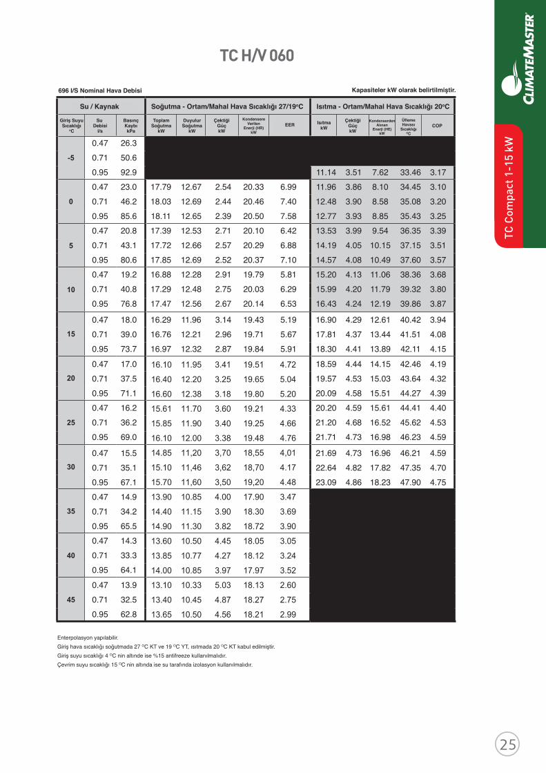
Revised: 8 April, 2016
ClimateMaster works continually to improve its products. As a result, the design and specifi cations of each product at the time of order may be changed without notice and may not be as described herein. Please contact ClimateMaster's Customer Service Department at 1-405-745-6000 for specifi c information on the current design and specifi cations. Statements and other information contained herein are not express warranties and do not form the basis of any bargainbetween the parties, but are merely ClimateMaster's opinion or commendation of its products. The latest version of this document is available at climatemaster.com.
Page ______ of ______LC406 - 15
TC Series 50Hz - HFC410A Submittal Data Eng/S-I
Performance Data - TC H/V 048
WATER / BRINE COOLING - EAT 27/19 °C HEATING - EAT 20°C
EWT°C
FLOWl/s
PDkPa TC kW SC
kWPower
kW HR kW
EERW/W
HCkW
PowerkW
HEkW LAT COP
W/W
-5Operation not recommended
0
5
10
15
20
25
30
35
Operation not recommended40
45
549 l/S Nominal Airfl ow
Interpolation is permissible; extrapolation is not.All entering air conditions are 27°C DB and 19°C WB in cooling and 20°C DB in heating.AHRI/ISO certifi ed conditions are 27°C DB and 19°C WB in cooling and 20°C DB in heating. Table does not refl ect fan or pump power corrections for AHRI/ISO conditions.All performance data is based upon the lower voltage of dual voltage rated units.Performance stated is at the rated power supply; performance may vary as the power supply varies from the rated.Operation below 4°C EWT is based upon a 15% methanol antifreeze solution.Operation below 16°C EWT requires optional insulated water/refrigerant circuit.See performance correction tables for operating conditions other than those listed above.Gray shaded area refers to calculations required to determine if heating water fl ow is suffi cient for non-antifreeze systems.
0.38 13.4 0.57 24.9 0.76 45.1 8.11 2.49 5.62 32.25 3.25 0.38 11.9 14.70 10.49 1.92 16.62 7.65 8.72 2.73 5.99 33.16 3.19 0.57 22.9 14.98 10.54 1.80 16.78 8.31 9.05 2.76 6.30 33.67 3.29 0.76 41.9 15.11 10.55 1.75 16.85 8.64 9.24 2.77 6.47 33.95 3.34 0.38 10.9 14.31 10.36 2.09 16.40 6.85 9.81 2.80 7.01 34.81 3.50 0.57 21.5 14.63 10.47 1.95 16.58 7.50 10.23 2.83 7.41 35.45 3.62 0.76 39.6 14.78 10.51 1.89 16.67 7.83 10.47 2.84 7.63 35.80 3.68 0.38 10.1 13.86 10.18 2.28 16.14 6.07 10.97 2.87 8.10 36.57 3.82 0.57 20.4 14.22 10.33 2.12 16.35 6.69 11.49 2.90 8.58 37.34 3.96 0.76 37.9 14.40 10.39 2.05 16.45 7.02 11.77 2.92 8.85 37.76 4.03
0.38 9.6 13.35 9.95 2.51 15.86 5.32 12.18 2.94 9.24 38.39 4.14 0.57 19.6 13.76 10.13 2.33 16.08 5.91 12.77 2.98 9.79 39.28 4.29 0.76 36.5 13.95 10.21 2.24 16.19 6.22 13.10 3.00 10.10 39.78 4.37 0.38 9.1 12.80 9.69 2.77 15.56 4.62 13.40 3.02 10.38 40.23 4.44 0.57 18.9 13.23 9.89 2.56 15.80 5.16 14.07 3.06 11.01 41.25 4.60 0.76 35.3 13.44 9.99 2.47 15.91 5.45 14.44 3.09 11.35 41.80 4.68
0.38 8.7 12.19 9.40 3.07 15.25 3.98 14.62 3.10 11.53 42.08 4.72 0.57 18.3 12.66 9.62 2.84 15.49 4.46 15.35 3.15 12.21 43.18 4.88 0.76 34.4 12.88 9.73 2.73 15.61 4.72 15.74 3.18 12.57 43.77 4.96 0.38 8.4 11.53 9.10 3.40 14.94 3.39 15.82 3.18 12.64 43.88 4.97 0.57 17.8 12.03 9.33 3.15 15.17 3.82 16.58 3.24 13.35 45.04 5.12 0.76 33.5 12.27 9.44 3.03 15.29 4.06 16.99 3.27 13.72 45.64 5.19 0.38 8.1 10.83 8.78 3.79 14.62 2.86 0.57 17.4 11.35 9.01 3.50 14.85 3.24 0.76 32.7 11.60 9.13 3.37 14.97 3.45
0.38 7.9 10.08 8.44 4.22 14.30 2.39 0.57 16.9 10.62 8.69 3.90 14.53 2.72 0.76 32.1 10.89 8.81 3.75 14.64 2.90 0.38 7.6 9.29 8.09 4.70 13.99 1.98 0.57 16.6 9.85 8.34 4.35 14.21 2.26 0.76 31.5 10.13 8.47 4.19 14.32 2.42
Performance capacities shown in kW
TC H/V 060
Revised: 8 April, 2016
ClimateMaster works continually to improve its products. As a result, the design and specifi cations of each product at the time of order may be changed without notice and may not be as described herein. Please contact ClimateMaster's Customer Service Department at 1-405-745-6000 for specifi c information on the current design and specifi cations. Statements and other information contained herein are not express warranties and do not form the basis of any bargainbetween the parties, but are merely ClimateMaster's opinion or commendation of its products. The latest version of this document is available at climatemaster.com.
Page ______ of ______LC406 - 16
TC Series 50Hz - HFC410A Submittal Data Eng/S-I
Performance Data - TC H/V 060
WATER / BRINE COOLING - EAT 27/19 °C HEATING - EAT 20°C
EWT°C
FLOWl/s
PDkPa TC kW SC
kWPower
kW HR kW
EERW/W
HCkW
PowerkW
HEkW LAT COP
W/W
-5Operation not recommended
0
5
10
15
20
25
30
35
Operation not recommended40
45
686 l/s Nominal Airfl ow
Interpolation is permissible; extrapolation is not.All entering air conditions are 27°C DB and 19°C WB in cooling and 20°C DB in heating.AHRI/ISO certifi ed conditions are 27°C DB and 19°C WB in cooling and 20°C DB in heating. Table does not refl ect fan or pump power corrections for AHRI/ISO conditions.All performance data is based upon the lower voltage of dual voltage rated units.Performance stated is at the rated power supply; performance may vary as the power supply varies from the rated.Operation below 4°C EWT is based upon a 15% methanol antifreeze solution.Operation below 16°C EWT requires optional insulated water/refrigerant circuit.See performance correction tables for operating conditions other than those listed above.Gray shaded area refers to calculations required to determine if heating water fl ow is suffi cient for non-antifreeze systems.
0.47 26.3 0.71 50.6 0.95 92.9 11.14 3.51 7.62 33.46 3.17 0.47 23.0 17.79 12.67 2.54 20.33 6.99 11.96 3.86 8.10 34.45 3.10 0.71 46.2 18.03 12.69 2.44 20.46 7.40 12.48 3.90 8.58 35.08 3.20 0.95 85.6 18.11 12.65 2.39 20.50 7.58 12.77 3.93 8.85 35.43 3.25 0.47 20.8 17.39 12.53 2.71 20.10 6.42 13.53 3.99 9.54 36.35 3.39 0.71 43.1 17.72 12.66 2.57 20.29 6.88 14.19 4.05 10.15 37.15 3.51 0.95 80.6 17.85 12.69 2.52 20.37 7.10 14.57 4.08 10.49 37.60 3.57 0.47 19.2 16.88 12.28 2.91 19.79 5.81 15.20 4.13 11.06 38.36 3.68 0.71 40.8 17.29 12.48 2.75 20.03 6.29 15.99 4.20 11.79 39.32 3.80 0.95 76.8 17.47 12.56 2.67 20.14 6.53 16.43 4.24 12.19 39.86 3.87
0.47 18.0 16.29 11.96 3.14 19.43 5.19 16.90 4.29 12.61 40.42 3.94 0.71 39.0 16.76 12.21 2.96 19.71 5.67 17.81 4.37 13.44 41.51 4.08 0.95 73.7 16.97 12.32 2.87 19.84 5.91 18.30 4.41 13.89 42.11 4.15 0.47 17.0 15.63 11.60 3.41 19.05 4.58 18.59 4.44 14.15 42.46 4.19 0.71 37.5 16.14 11.87 3.20 19.34 5.04 19.57 4.53 15.03 43.64 4.32 0.95 71.1 16.39 12.01 3.10 19.49 5.28 20.09 4.58 15.51 44.27 4.39 0.47 16.2 14.91 11.23 3.73 18.64 4.00 20.20 4.59 15.61 44.41 4.40 0.71 36.2 15.45 11.50 3.49 18.94 4.43 21.20 4.68 16.52 45.62 4.53 0.95 69.0 15.72 11.64 3.38 19.10 4.65 21.71 4.73 16.98 46.23 4.59
0.47 15.5 14.14 10.87 4.09 18.23 3.45 21.69 4.73 16.96 46.21 4.59 0.71 35.1 14.70 11.13 3.82 18.53 3.84 22.64 4.82 17.82 47.35 4.70 0.95 67.1 14.98 11.27 3.70 18.68 4.05 23.09 4.86 18.23 47.90 4.75 0.47 14.9 13.33 10.54 4.50 17.83 2.96 0.71 34.2 13.91 10.77 4.20 18.11 3.31 0.95 65.5 14.20 10.90 4.06 18.26 3.50 0.47 14.3 12.50 10.26 4.97 17.47 2.52 0.71 33.3 13.08 10.45 4.64 17.72 2.82 0.95 64.1 13.38 10.56 4.48 17.86 2.99 0.47 13.9 11.66 10.03 5.49 17.14 2.13 0.71 32.5 12.24 10.18 5.12 17.36 2.39 0.95 62.8 12.53 10.27 4.95 17.48 2.53
Performance capacities shown in kW696 I/S Nominal Hava Debisi
Giriş SuyuSıcaklığı
oC
Su Debisi
l/s
BasınçKaybıkPa
ToplamSoğutma
kW
DuyulurSoğutma
kW
ÇektiğiGüçkW
ÇektiğiGüçkW
IsıtmakW
Enterpolasyon yapılabilir. Giriş hava sıcaklığı soğutmada 27 OC KT ve 19 OC YT, ısıtmada 20 OC KT kabul edilmiştir.Giriş suyu sıcaklığı 4 OC nin altınde ise %15 antifreeze kullanılmalıdır.Çevrim suyu sıcaklığı 15 OC nin altında ise su tarafında izolasyon kullanılmalıdır.
ÜflemeHavası
SıcaklığıOC
KondenserdenAlınan
Enerji (HE)kW
COPKondensere
VerilenEnerji (HR)
kW
EER
Soğutma - Ortam/Mahal Hava Sıcaklığı 27/19oCSu / Kaynak Isıtma - Ortam/Mahal Hava Sıcaklığı 20oC
Kapasiteler kW olarak belirtilmiştir.
TC C
ompa
ct 1
-15
kW
16.10
16.40
16.60
15.61
15.85
16.10
14.85
15.10
15.70
13.90
14.40
14.90
13.60
13.85
14.00
13.10
13.40
13.65
11.95
12.20
12.38
11.70
11.90
12.00
11,20
11,46
11,60
10.85
11.15
11.30
10.50
10.77
10.85
10.33
10.45
10.50
3.41
3.25
3.18
3.60
3.40
3.38
3,70
3,62
3,50
4.00
3.90
3.82
4.45
4.27
3.97
5.03
4.87
4.56
19.51
19.65
19.80
19.21
19.25
19.48
18,55
18,70
19,20
17.90
18.30
18.72
18.05
18.12
17.97
18.13
18.27
18.21
4.72
5.04
5.20
4.33
4.66
4.76
4,01
4.17
4.48
3.47
3.69
3.90
3.05
3.24
3.52
2.60
2.75
2.99
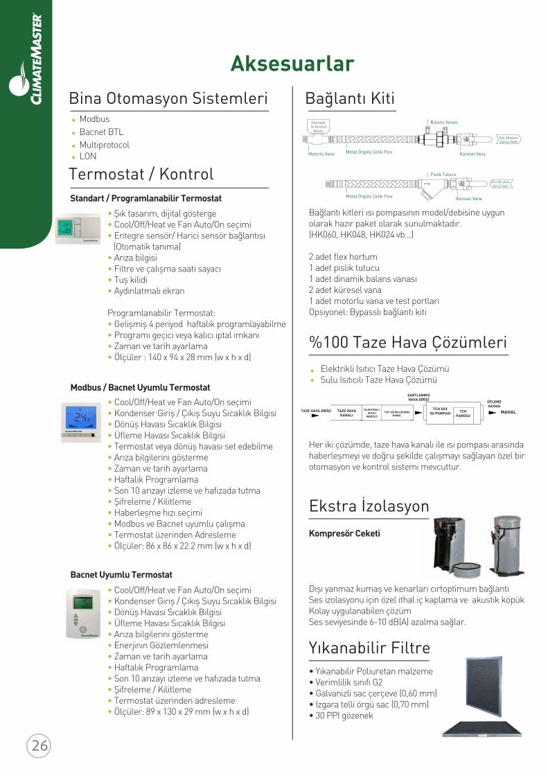
Aksesuarlar
Otomatik Isı Kontrol
Vanası
Motorlu Vana Metal Örgülü Çelik Flex
Balans Vanası
Küresel Vana
Küresel Vana
Pislik Tutucu
Metal Örgülü Çelik Flex
Sıvı Akışkan Dönüş Hattı
Sıvı Akışkan Giriş Hattı
Bağlantı Kiti
Bağlantı kitleri ısı pompasının model/debisine uygun olarak hazır paket olarak sunulmaktadır. (HK060, HK048, HK024 vb...)
2 adet flex hortum1 adet pislik tutucu1 adet dinamik balans vanası2 adet küresel vana1 adet motorlu vana ve test portlarıOpsiyonel: Bypasslı bağlantı kiti
Her iki çözümde, taze hava kanalı ile ısı pompası arasında haberleşmeyi ve doğru şekilde çalışmayı sağlayan özel bir otomasyon ve kontrol sistemi mevcuttur.
MAHAL
Kompresör Ceketi
Dışı yanmaz kumaş ve kenarları cırtoptimum bağlantıSes izolasyonu için özel ithal iç kaplama ve akustik köpük Kolay uygulanabilen çözümSes seviyesinde 6-10 dB(A) azalma sağlar.
• Yıkanabilir Poliuretan malzeme• Verimlilik sınıfı G2• Galvanizli sac çerçeve (0,60 mm)• Izgara telli örgü sac (0,70 mm) • 30 PPI gözenek
Bina Otomasyon SistemleriModbusBacnet BTLMultiprotocolLON
Termostat / KontrolStandart / Programlanabilir Termostat
• Şık tasarım, dijital gösterge• Cool/Off/Heat ve Fan Auto/On seçimi• Entegre sensör/ Harici sensör bağlantısı (Otomatik tanıma)• Arıza bilgisi• Filtre ve çalışma saati sayacı• Tuş kilidi• Aydınlatmalı ekran Programlanabilir Termostat:• Gelişmiş 4 periyod haftalık programlayabilme• Programı geçici veya kalıcı iptal imkanı• Zaman ve tarih ayarlama• Ölçüler : 140 x 94 x 28 mm (w x h x d)
• Cool/Off/Heat ve Fan Auto/On seçimi• Kondenser Giriş / Çıkış Suyu Sıcaklık Bilgisi• Dönüş Havası Sıcaklık Bilgisi• Üfleme Havası Sıcaklık Bilgisi• Termostat veya dönüş havası set edebilme• Arıza bilgilerini gösterme• Zaman ve tarih ayarlama• Haftalık Programlama• Son 10 arızayı izleme ve hafızada tutma• Şifreleme / Kilitleme• Haberleşme hızı seçimi• Modbus ve Bacnet uyumlu çalışma• Termostat üzerinden Adresleme• Ölçüler: 86 x 86 x 22.2 mm (w x h x d)
• Cool/Off/Heat ve Fan Auto/On seçimi• Kondenser Giriş / Çıkış Suyu Sıcaklık Bilgisi• Dönüş Havası Sıcaklık Bilgisi• Üfleme Havası Sıcaklık Bilgisi• Arıza bilgilerini gösterme• Enerjinin Gözlemlenmesi• Zaman ve tarih ayarlama• Haftalık Programlama• Son 10 arızayı izleme ve hafızada tutma• Şifreleme / Kilitleme• Termostat üzerinden adresleme• Ölçüler: 89 x 130 x 29 mm (w x h x d)
%100 Taze Hava Çözümleri
Ekstra İzolasyon
Yıkanabilir Filtre
Modbus / Bacnet Uyumlu Termostat
Bacnet Uyumlu Termostat
Elektrikli Isıtıcı Taze Hava ÇözümüSulu Isıtıcılı Taze Hava Çözümü
TAZE HAVA GİRİŞİ TAZE HAVAKANALI
ELEKTRİKLİISITICI
MODÜLÜ1 MT UZUNLUĞUNDA
KANAL
ŞARTLANMIŞHAVA GİRİŞİ ÜFLEME
HAVASITCH XXX
ISI POMPASI TCHPANOSU
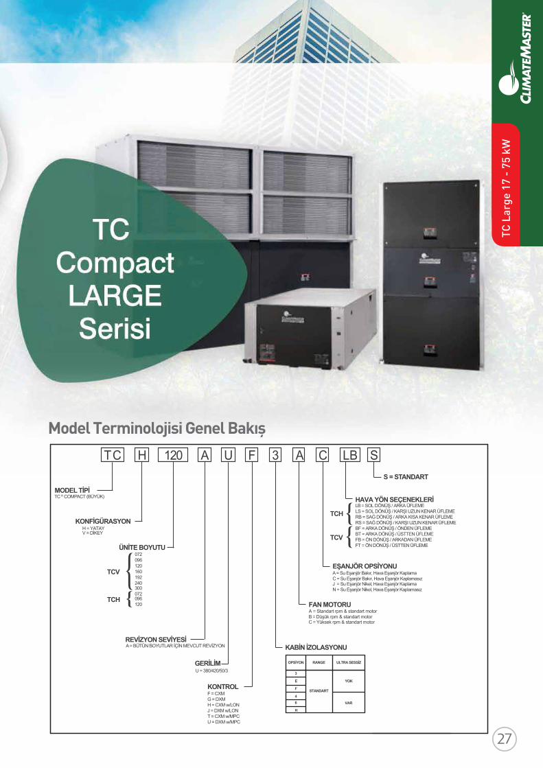
Model Terminolojisi Genel BakışT C H A120 FU 3 A C LB S
8
TC ® COMPACT (BÜYÜK)MODEL TİPİ
H = YATAYKONFİGÜRASYON
V = DİKEY
ÜNİTE BOYUTU072 096120160192240
REVİZYON SEVİYESİA = BÜTÜN BOYUTLAR İÇİN MEVCUT REVİZYON
GERİLİM
F = CXMKONTROL
G = DXMH = CXM w/LONJ = DXM w/LONT = CXM w/MPCU = DXM w/MPC
KABİN İZOLASYONU
FAN MOTORU
A = Su Eşanjör Bakır, Hava Eşanjör KaplamaEŞANJÖR OPSİYONUC = Su Eşanjör Bakır, Hava Eşanjör Kaplamasız
LB = SOL DÖNÜŞ / ARKA ÜFLEMEHAVA YÖN SEÇENEKLERİLS = SOL DÖNÜŞ / KARŞI UZUN KENAR ÜFLEMERB = SAĞ DÖNÜŞ / ARKA KISA KENAR ÜFLEMERS = SAĞ DÖNÜŞ / KARŞI UZUN KENAR ÜFLEMEBF = ARKA DÖNÜŞ / ÖNDEN ÜFLEMEBT = ARKA DÖNÜŞ / ÜSTTEN ÜFLEMEFB = ÖN DÖNÜŞ / ARKADAN ÜFLEMEFT = ÖN DÖNÜŞ / ÜSTTEN ÜFLEME
S = STANDART
J = Su Eşanjör Nikel, Hava Eşanjör Kaplama
A = Standart rpm & standart motorB = Düşük rpm & standart motorC = Yüksek rpm & standart motor
N = Su Eşanjör Nikel, Hava Eşanjör Kaplamasız
TCV
TCH
TCH
TCV
300072096120
U = 380/420/50/3
OPSİYON RANGE ULTRA SESSİZ
YOK
STANDART
3
E
F
46
H
VAR
TC L
arge
17
- 75
kW
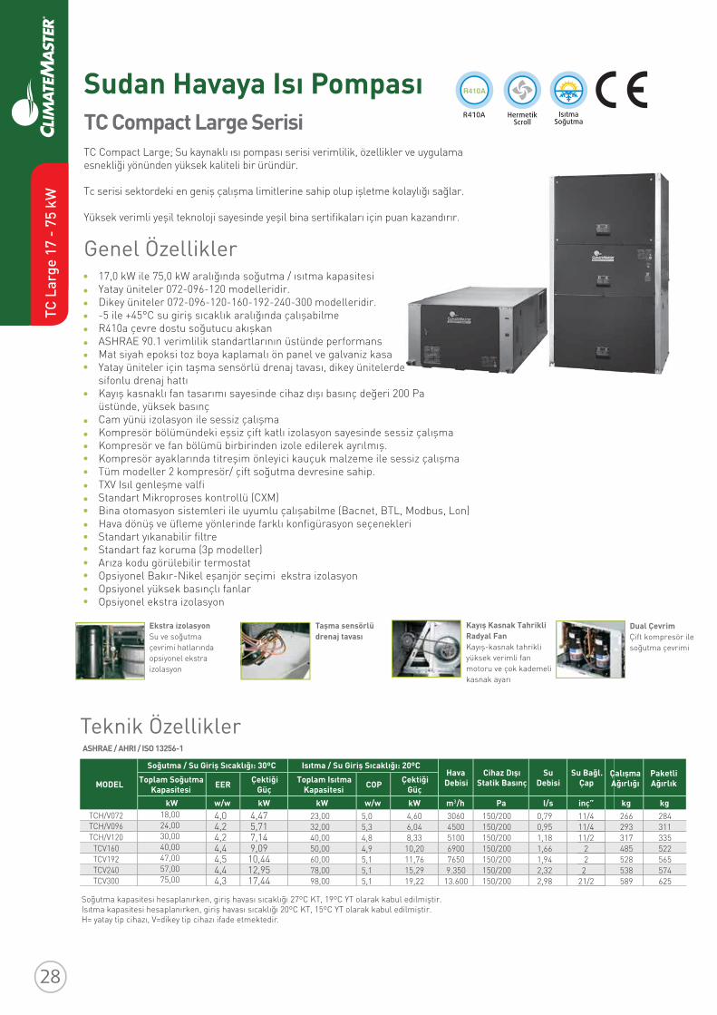
Soğutma kapasitesi hesaplanırken, giriş havası sıcaklığı 27ºC KT, 19ºC YT olarak kabul edilmiştir.Isıtma kapasitesi hesaplanırken, giriş havası sıcaklığı 20ºC KT, 15ºC YT olarak kabul edilmiştir.H= yatay tip cihazı, V=dikey tip cihazı ifade etmektedir.
ClimateMaster works continually to improve its products. As a result, the design and specifi cations of each product at the time of order may be changed without notice and may not be as described herein. Please contact ClimateMaster's Customer Service Department at +1-405-745-6000 for specifi c information on the current design and specifi cations. Statements and other information contained herein are not express warranties and do not form the basis of any bargain between the parties, but are merely ClimateMaster's opinion or commendation of its products. The latest version of this document is available at climatemaster.com.
Revised: 14 August, 2015
*EP016* EP016 Revised: 14 August, 2015
TRANQUILITY® COMPACT
BELT DRIVE (TCH/V) SERIES
SUBMITTAL DATA
MODELS TCH072 - 120
TCV072 - 300
50HZ - HFC-410A
ENGLISH LANGUAGE/S-I UNITS
SUBMITTAL DATA - S-I UNITS
Unit Designation:
Job Name:
Architect:
Engineer:
Contractor:
PERFORMANCE DATA
Cooling Capacity: kW
EER:
Heating Capacity: kW
COP:
Ambient Air Temp: °C
Entering Water Temp (Clg): °C
Entering Air Temp (Clg): °C
Entering Water Temp (Htg): °C
Entering Air Temp (Htg): °C
Airfl ow: l/s
Fan Speed or Motor/RPM/Turns:
Operating Weight: (kg)
ELECTRICAL DATA
Power Supply: Volts
Phase Hz
Minimum Circuit Ampacity:
Maximum Overcurrent Protection:
17,0 kW ile 75,0 kW aralığında soğutma / ısıtma kapasitesiYatay üniteler 072-096-120 modelleridir. Dikey üniteler 072-096-120-160-192-240-300 modelleridir.-5 ile +45°C su giriş sıcaklık aralığında çalışabilmeR410a çevre dostu soğutucu akışkanASHRAE 90.1 verimlilik standartlarının üstünde performansMat siyah epoksi toz boya kaplamalı ön panel ve galvaniz kasa Yatay üniteler için taşma sensörlü drenaj tavası, dikey ünitelerde sifonlu drenaj hattı Kayış kasnaklı fan tasarımı sayesinde cihaz dışı basınç değeri 200 Pa üstünde, yüksek basınç Cam yünü izolasyon ile sessiz çalışma Kompresör bölümündeki eşsiz çift katlı izolasyon sayesinde sessiz çalışma Kompresör ve fan bölümü birbirinden izole edilerek ayrılmış. Kompresör ayaklarında titreşim önleyici kauçuk malzeme ile sessiz çalışmaTüm modeller 2 kompresör/ çift soğutma devresine sahip.TXV Isıl genleşme valfi Standart Mikroproses kontrollü (CXM)Bina otomasyon sistemleri ile uyumlu çalışabilme (Bacnet, BTL, Modbus, Lon) Hava dönüş ve üfleme yönlerinde farklı konfigürasyon seçenekleriStandart yıkanabilir filtreStandart faz koruma (3p modeller)Arıza kodu görülebilir termostatOpsiyonel Bakır-Nikel eşanjör seçimi ekstra izolasyonOpsiyonel yüksek basınçlı fanlar Opsiyonel ekstra izolasyon
TC Compact Large Serisi
Sudan Havaya Isı Pompası
Genel Özellikler
TC Compact Large; Su kaynaklı ısı pompası serisi verimlilik, özellikler ve uygulama esnekliği yönünden yüksek kaliteli bir üründür.
Tc serisi sektordeki en geniş çalışma limitlerine sahip olup işletme kolaylığı sağlar.
Yüksek verimli yeşil teknoloji sayesinde yeşil bina sertifikaları için puan kazandırır.
Ekstra izolasyonSu ve soğutma çevrimi hatlarında opsiyonel ekstra izolasyon
Taşma sensörlü drenaj tavası
Dual ÇevrimÇift kompresör ile soğutma çevrimi
Kayış Kasnak Tahrikli Radyal FanKayış-kasnak tahrikli yüksek verimli fanmotoru ve çok kademeli kasnak ayarı
MODELHava
DebisiCihaz Dışı
Statik BasınçSu
DebisiSu Bağl.
ÇapToplam Soğutma
Soğutma / Su Giriş Sıcaklığı: 30ºC Isıtma / Su Giriş Sıcaklığı: 20ºC
Kapasitesi EER Çektiği Güç
Toplam IsıtmaKapasitesi COP Çektiği
GüçkW w/w kW kW w/w kW m /h Pa I/s inç”
ÇalışmaAğırlığı
kg
PaketliAğırlık
kgTCH/V072TCH/V096TCH/V120
TCV160TCV192TCV240TCV300
18,0024,0030,0040,0047,0057,0075,00
4,475,717,149,09
10,4412,9517,44
4,04,24,24,44,54,44,3
23,0032,0040,0050,0060,0078,0098,00
4,606,048,33
10,2011,7615,2919,22
306045005100690076509.350
13.600
150/200150/200150/200150/200150/200150/200150/200
0,790,951,181,661,942,322,98
11/411/411/2
22
2 21/2
266293317485528538589
284311335522565574625
5,05,34,84,95,15,15,1
Teknik ÖzelliklerASHRAE / AHRI / ISO 13256-1
ClimateMaster works continually to improve its products. As a result, the design and specifi cations of each product at the time of order may be changed without notice and may not be as described herein. Please contact ClimateMaster's Customer Service Department at +1-405-745-6000 for specifi c information on the current design and specifi cations. Statements and other information contained herein are not express warranties and do not form the basis of any bargainbetween the parties, but are merely ClimateMaster's opinion or commendation of its products. The latest version of this document is available at climatemaster.com.
Page ______ of ______Revised: 8 April, 2016EP016 - 24
Tranquility Compact belt Drive (TCH/V) Series 50Hz - HFC-410A Submittal Data Eng/S-I
Model
Overall Cabinet Discharge ConnectionsDuct Flange Water Connections Electrical Knockouts Return Air Connections
Using Return Air OpeningA
Depth
B
Width
C
Height
D E
SupplyDepth
F
SupplyWidth
G
SupplyHeight
K L
1WaterOutlet
M
2WaterInlet
O P Q R S
ReturnDepth
T
ReturnHeight
U V
072-120 cm. 92.2 215.6 54.9 35.6 43.2 34.3 19.8 38.1 21.1 10.2 5.1 47.8 42.7 35.1 165.1 45.7 2.5 48.0
HANGER BRACKET DIMENSIONS221cm
2.54cm
PLAN VIEWTOP
10.8cm
86.6cm
FRO
NT
CONTROL BOX
U
T
S V
3.3cmcondensate LEFT RETURN LEFT VIEW-
AIR COIL SIDE
LEFT RETURN END DISCHARGE
CBP
EAP
BSP
CAP
CAP
FRONT
ED
F
G
CAP
CBP
CAP
EAP
BSP
FRONT
FRO
NT
CONTROL BOX
PLAN VIEWTOP
V S U
RIGHT RETURN RIGHT VIEW-AIR COIL SIDE
RIGHT RETURN END DISCHARGE
3.3cmcondensate drain
3
NOTES:- All dimensions in cm.- Units require 91 cm clearance for water connections, CAP, CSP, EAP and BSP service access.- Overall cabinet width dimensions does not include filter rail and duct flange.
TCH072-120 Dimensional Data
LEFT RETURN STRAIGHT DISCHARGE
CAP
CAP
FRONT
BSPA
EAP
CBP
BC
O
PQRK
M
F
G E
D
BSP
RIGHT RETURN STRAIGHT DISCHARGE
1EAP
2 CAP
CAP 2
FRONT
CBP1
5
4
LEGENDCAP=Compressor Access PanelCBP=Control Box PanelBSP=Blower Service PanelEAP=Expansion Valve Access panel1=Water Outlet 1-1/4” FPT (072-096) 1-1/2” FPT (120)2=Water Inlet 1-1/4” FPT (072-096) 1-1/2” FPT (120)3=Condensate 3/4” FPT4=High Voltage [2.9cm] KO5=Low Voltage [2.2cm] KO
SERVICE ACCESS91 cm TYPICALALL CONFIGURATIONS
NOTES FOR LEGEND:1. Access is required for all removable panels and installer should take care to comply with
all building codes and allow adequate clearance for future field service.
2. Water inlet and water outlet connections are available on either side (left or right) of the unit. Qty (2x) MPT Plugs are shipped loose in a plastic bag tied to the water leg in front of the unit. Installer must plug water inlet/outlet side not being connected to.
3. Condensate drain is available on end opposite compressor.
4. Electrical access is available on either side (left or right) of the front.
5. Electric box is on right side. It can be field converted to left side. Conversion should only be attempted by qualified service technician.
TC L
arge
17
- 75
kW
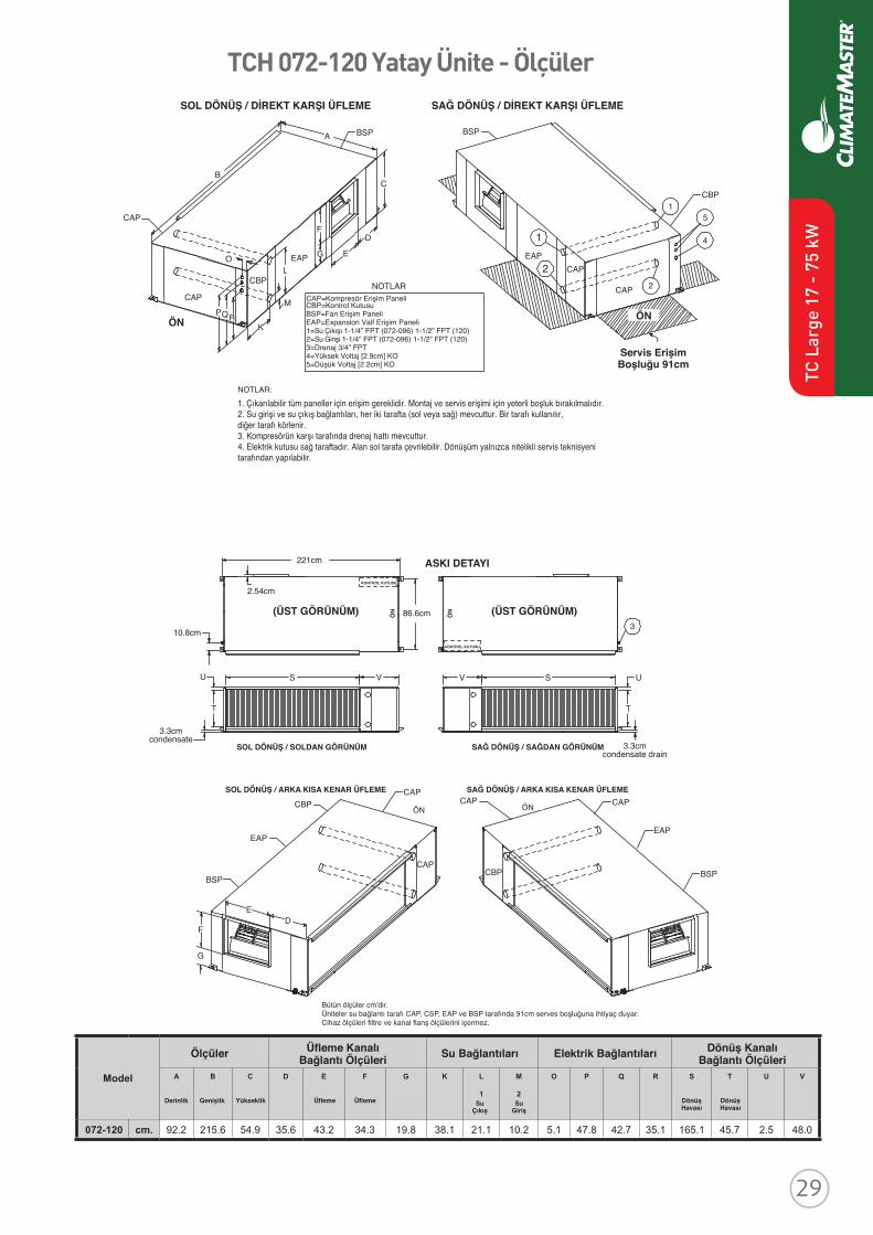
ClimateMaster works continually to improve its products. As a result, the design and specifi cations of each product at the time of order may be changed without notice and may not be as described herein. Please contact ClimateMaster's Customer Service Department at +1-405-745-6000 for specifi c information on the current design and specifi cations. Statements and other information contained herein are not express warranties and do not form the basis of any bargain between the parties, but are merely ClimateMaster's opinion or commendation of its products. The latest version of this document is available at climatemaster.com.
Revised: 14 August, 2015
*EP016* EP016 Revised: 14 August, 2015
TRANQUILITY® COMPACT
BELT DRIVE (TCH/V) SERIES
SUBMITTAL DATA
MODELS TCH072 - 120
TCV072 - 300
50HZ - HFC-410A
ENGLISH LANGUAGE/S-I UNITS
SUBMITTAL DATA - S-I UNITS
Unit Designation:
Job Name:
Architect:
Engineer:
Contractor:
PERFORMANCE DATA
Cooling Capacity: kW
EER:
Heating Capacity: kW
COP:
Ambient Air Temp: °C
Entering Water Temp (Clg): °C
Entering Air Temp (Clg): °C
Entering Water Temp (Htg): °C
Entering Air Temp (Htg): °C
Airfl ow: l/s
Fan Speed or Motor/RPM/Turns:
Operating Weight: (kg)
ELECTRICAL DATA
Power Supply: Volts
Phase Hz
Minimum Circuit Ampacity:
Maximum Overcurrent Protection:
TCH 072-120 Yatay Ünite - Ölçüler
ClimateMaster works continually to improve its products. As a result, the design and specifi cations of each product at the time of order may be changed without notice and may not be as described herein. Please contact ClimateMaster's Customer Service Department at +1-405-745-6000 for specifi c information on the current design and specifi cations. Statements and other information contained herein are not express warranties and do not form the basis of any bargainbetween the parties, but are merely ClimateMaster's opinion or commendation of its products. The latest version of this document is available at climatemaster.com.
Page ______ of ______Revised: 8 April, 2016EP016 - 24
Tranquility Compact belt Drive (TCH/V) Series 50Hz - HFC-410A Submittal Data Eng/S-I
Model
Overall Cabinet Discharge ConnectionsDuct Flange Water Connections Electrical Knockouts Return Air Connections
Using Return Air OpeningA
Depth
B
Width
C
Height
D E
SupplyDepth
F
SupplyWidth
G
SupplyHeight
K L
1WaterOutlet
M
2WaterInlet
O P Q R S
ReturnDepth
T
ReturnHeight
U V
072-120 cm. 92.2 215.6 54.9 35.6 43.2 34.3 19.8 38.1 21.1 10.2 5.1 47.8 42.7 35.1 165.1 45.7 2.5 48.0
HANGER BRACKET DIMENSIONS221cm
2.54cm
PLAN VIEWTOP
10.8cm
86.6cm
FRO
NT
CONTROL BOX
U
T
S V
3.3cmcondensate LEFT RETURN LEFT VIEW-
AIR COIL SIDE
LEFT RETURN END DISCHARGE
CBP
EAP
BSP
CAP
CAP
FRONT
ED
F
G
CAP
CBP
CAP
EAP
BSP
FRONT
FRO
NT
CONTROL BOX
PLAN VIEWTOP
V S U
RIGHT RETURN RIGHT VIEW-AIR COIL SIDE
RIGHT RETURN END DISCHARGE
3.3cmcondensate drain
3
NOTES:- All dimensions in cm.- Units require 91 cm clearance for water connections, CAP, CSP, EAP and BSP service access.- Overall cabinet width dimensions does not include filter rail and duct flange.
TCH072-120 Dimensional Data
LEFT RETURN STRAIGHT DISCHARGE
CAP
CAP
FRONT
BSPA
EAP
CBP
BC
O
PQRK
M
F
G E
D
BSP
RIGHT RETURN STRAIGHT DISCHARGE
1EAP
2 CAP
CAP 2
FRONT
CBP1
5
4
LEGENDCAP=Compressor Access PanelCBP=Control Box PanelBSP=Blower Service PanelEAP=Expansion Valve Access panel1=Water Outlet 1-1/4” FPT (072-096) 1-1/2” FPT (120)2=Water Inlet 1-1/4” FPT (072-096) 1-1/2” FPT (120)3=Condensate 3/4” FPT4=High Voltage [2.9cm] KO5=Low Voltage [2.2cm] KO
SERVICE ACCESS91 cm TYPICALALL CONFIGURATIONS
NOTES FOR LEGEND:1. Access is required for all removable panels and installer should take care to comply with
all building codes and allow adequate clearance for future field service.
2. Water inlet and water outlet connections are available on either side (left or right) of the unit. Qty (2x) MPT Plugs are shipped loose in a plastic bag tied to the water leg in front of the unit. Installer must plug water inlet/outlet side not being connected to.
3. Condensate drain is available on end opposite compressor.
4. Electrical access is available on either side (left or right) of the front.
5. Electric box is on right side. It can be field converted to left side. Conversion should only be attempted by qualified service technician.
1. Çıkarılabilir tüm paneller için erişim gereklidir. Montaj ve servis erişimi için yeterli boşluk bırakılmalıdır.2. Su girişi ve su çıkış bağlantıları, her iki tarafta (sol veya sağ) mevcuttur. Bir tarafı kullanılır,diğer tarafı körlenir.3. Kompresörün karşı tarafında drenaj hattı mevcuttur.4. Elektrik kutusu sağ taraftadır. Alan sol tarafa çevrilebilir. Dönüşüm yalnızca nitelikli servis teknisyeni tarafından yapılabilir.
NOTLAR:
NOTLARCAP=Kompresör Erişim PaneliCBP=Kontrol KutusuBSP=Fan Erişim PaneliEAP=Expansion Valf Erişim Paneli1=Su Çıkışı 1-1/4” FPT (072-096) 1-1/2” FPT (120)2=Su Girişi 1-1/4” FPT (072-096) 1-1/2” FPT (120)3=Drenaj 3/4” FPT4=Yüksek Voltaj [2.9cm] KO5=Düşük Voltaj [2.2cm] KO
SOL DÖNÜŞ / DİREKT KARŞI ÜFLEME SAĞ DÖNÜŞ / DİREKT KARŞI ÜFLEME
Servis ErişimBoşluğu 91cm
ÖN ÖN
ASKI DETAYI
(ÜST GÖRÜNÜM) (ÜST GÖRÜNÜM)
KONTROL KUTUSU
KONTROL KUTUSU
ÖN
ÖN
SOL DÖNÜŞ / SOLDAN GÖRÜNÜM SAĞ DÖNÜŞ / SAĞDAN GÖRÜNÜM
SOL DÖNÜŞ / ARKA KISA KENAR ÜFLEME
ÖN ÖN
SAĞ DÖNÜŞ / ARKA KISA KENAR ÜFLEME
Bütün ölçüler cm’dir.Üniteler su bağlantı tarafı CAP, CSP, EAP ve BSP tarafında 91cm serves boşluğuna ihtiyaç duyar.Cihaz ölçüleri filtre ve kanal flanş ölçülerini içermez.
Ölçüler Su Bağlantıları Elektrik BağlantılarıÜfleme KanalıBağlantı Ölçüleri
Dönüş KanalıBağlantı Ölçüleri
Derinlik Genişlik Yükseklik Üfleme Üfleme DönüşHavası
DönüşHavasıSu
ÇıkışSu
Giriş
TC L
arge
17
- 75
kW
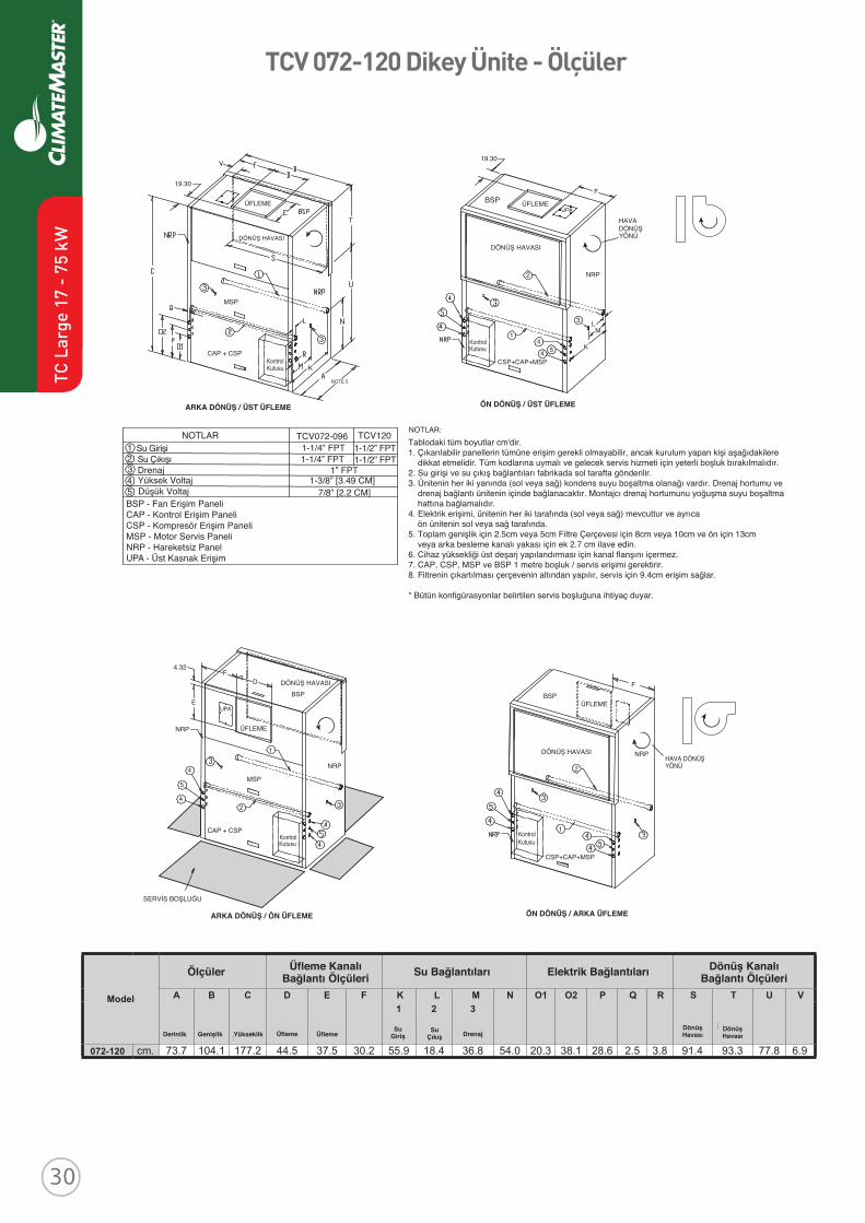
Revised: 8 April, 2016
ClimateMaster works continually to improve its products. As a result, the design and specifi cations of each product at the time of order may be changed without notice and may not be as described herein. Please contact ClimateMaster's Customer Service Department at 1-405-745-6000 for specifi c information on the current design and specifi cations. Statements and other information contained herein are not express warranties and do not form the basis of any bargainbetween the parties, but are merely ClimateMaster's opinion or commendation of its products. The latest version of this document is available at climatemaster.com.
Page ______ of ______LC406 - 21
TC Series 50Hz - HFC410A Submittal Data Eng/S-I
TC - Horizontal - Dimensional Data
HorizontalModel
Overall Cabinet
AWidth
BLength
CHeight
006 - 012 cm 48.5 86.6 27.9
015 - 018 cm 51.1 109.5 43.2
024 - 030 cm 51.1 109.5 46.5
036 - 042 cm 51.1 119.6 53.3
048 - 060 cm 61.2 137.4 53.3
HorizontalModel
Electrical Knockouts
H22.2mm
J22.2mm
K28.6mm
LowVoltage
LowVoltage
PowerSupply
006 - 012 cm 20.6 13.0 5.4
015 - 030 cm 30.8 23.2 15.6
036 - 060 cm 41.0 33.3 25.7
HorizontalModel
Discharge ConnectionDuct Flange Installed (+/- 2.5mm)
Return ConnectionUsing Return Air Opening
LM
SupplyHeight
NSupplyWidth
O PQ
ReturnWidth
RReturnHeight
S T
006 - 012 cm 1.9 22.7 17.0 13.3 3.3 41.0 25.0 2.7 1.5
015 - 018 cm 6.6 33.8 25.1 10.5 3.3 58.4 38.1 2.8 2.5
024 - 030 cm 6.6 33.8 25.1 10.5 3.3 58.4 41.4 2.8 2.5
036 - 042 cm 6.3 40.9 27.9 7.7 6.4 65.8 48.3 2.8 2.5
048 cm 9.5 41.0 34.8 10.3 3.2 91.2 48.3 2.8 2.5
060 cm 4.4 46.0 34.8 10.3 3.2 91.2 48.3 2.8 2.5
HorizontalModel
Water Connections
1 2 3LoopIn/OutFPT
LoopInD
LoopInE
LoopOutF
LoopOutG
Cond. 3/4” FPT
AA BB
006 - 012 cm 24.3 2.7 3.8 2.7 8.4 1.8 1/2”
015 cm 38.4 3.4 8.1 3.5 8.4 1.8 1/2”
018 cm 38.4 3.4 10.4 3.5 8.4 1.8 1/2”
024 cm 41.7 3.4 11.3 3.5 8.4 1.8 3/4”
030 cm 41.7 3.4 7.8 3.5 8.4 1.8 3/4”
036 cm 48.5 3.4 13.4 3.5 8.4 1.8 3/4”
042 cm 48.5 3.4 11.3 3.5 8.4 1.8 3/4”
048 cm 48.5 3.4 11.1 3.5 8.4 1.8 1”
060 cm 48.5 3.4 9.7 3.5 8.4 1.8 1”
TCV 072-120 Dikey Ünite - Ölçüler
Model
Overall Cabinet Discharge Connection Duct Flange Water Connections Electric Knockouts Return Air Connections Using
Return Air Opening
A B C D E F K L M N O1 O2 P Q R S T U V
Depth Width Height Supply Width
SupplyDepth
1
Water Inlet
2
Water Outlet
3
Con-densate
ReturnDepth
ReturnHeight
072-120 cm. 73.7 104.1 177.2 44.5 37.5 30.2 55.9 18.4 36.8 54.0 20.3 38.1 28.6 2.5 3.8 91.4 93.3 77.8 6.9
4.32
ÜFLEME
NRP
NRP
DÖNÜŞ HAVASI
UPA
BSP
2
4
4
5
1
E
FD
MSP
KontrolKutusu
CAP + CSP KontrolKutusu
NOTE 5
NOTLAR TCV072-096 TCV120Su GirişiSu ÇıkışıDrenajYüksek VoltajDüşük Voltaj
1-1/4” FPT1-1/4” FPT
1-1/2” FPT1-1/2” FPT
1” FPT1-3/8” [3.49 CM]
7/8” [2.2 CM]BSP - Fan Erişim Paneli CAP - Kontrol Erişim PaneliCSP - Kompresör Erişim PaneliMSP - Motor Servis PaneliNRP - Hareketsiz PanelUPA - Üst Kasnak Erişim
12345
ÖN DÖNÜŞ / ARKA ÜFLEMEARKA DÖNÜŞ / ÖN ÜFLEME
ARKA DÖNÜŞ / ÜST ÜFLEME ÖN DÖNÜŞ / ÜST ÜFLEME
NOTLAR:
19.30
CAP + CSP
MSP
ÜFLEME
NRP
HAVA DÖNÜŞYÖNÜ
DÖNÜŞ HAVASIDÖNÜŞ HAVASI
2
3
1
CSP+CAP+MSP
44 5
19.30
F
L
K
M
BSPUPA
ÜFLEME
NRPDÖNÜŞ HAVASI
BSP
2
CSP+CAP+MSP
1
F
KontrolKutusu
KontrolKutusu
Tablodaki tüm boyutlar cm'dir.1. Çıkarılabilir panellerin tümüne erişim gerekli olmayabilir, ancak kurulum yapan kişi aşağıdakilere dikkat etmelidir. Tüm kodlarına uymalı ve gelecek servis hizmeti için yeterli boşluk bırakılmalıdır.2. Su girişi ve su çıkış bağlantıları fabrikada sol tarafta gönderilir. 3. Ünitenin her iki yanında (sol veya sağ) kondens suyu boşaltma olanağı vardır. Drenaj hortumu ve drenaj bağlantı ünitenin içinde bağlanacaktır. Montajcı drenaj hortumunu yoğuşma suyu boşaltma hattına bağlamalıdır.4. Elektrik erişimi, ünitenin her iki tarafında (sol veya sağ) mevcuttur ve ayrıca ön ünitenin sol veya sağ tarafında.5. Toplam genişlik için 2.5cm veya 5cm Filtre Çerçevesi için 8cm veya 10cm ve ön için 13cm veya arka besleme kanalı yakası için ek 2.7 cm ilave edin.6. Cihaz yüksekliği üst deşarj yapılandırması için kanal flanşını içermez.7. CAP, CSP, MSP ve BSP 1 metre boşluk / servis erişimi gerektirir.8. Filtrenin çıkartılması çerçevenin altından yapılır, servis için 9.4cm erişim sağlar.
* Bütün konfigürasyonlar belirtilen servis boşluğuna ihtiyaç duyar.
ÜFLEME
SERVİS BOŞLUĞU
HAVA DÖNÜŞ YÖNÜ
Ölçüler Su Bağlantıları Elektrik BağlantılarıÜfleme KanalıBağlantı Ölçüleri
Dönüş KanalıBağlantı Ölçüleri
Derinlik Genişlik Yükseklik Üfleme ÜflemeDönüşHavası
DönüşHavası
SuGiriş
SuÇıkış Drenaj
TC L
arge
17
- 75
kW
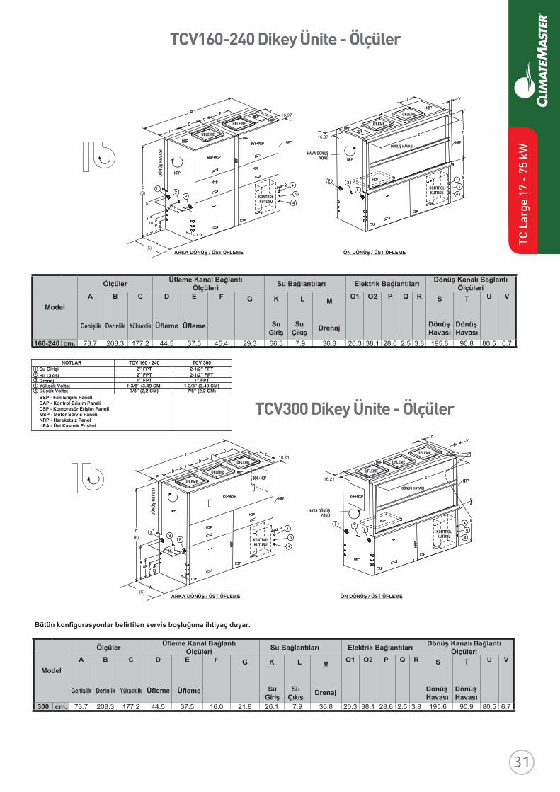
Revised: 8 April, 2016
ClimateMaster works continually to improve its products. As a result, the design and specifi cations of each product at the time of order may be changed without notice and may not be as described herein. Please contact ClimateMaster's Customer Service Department at 1-405-745-6000 for specifi c information on the current design and specifi cations. Statements and other information contained herein are not express warranties and do not form the basis of any bargainbetween the parties, but are merely ClimateMaster's opinion or commendation of its products. The latest version of this document is available at climatemaster.com.
Page ______ of ______LC406 - 21
TC Series 50Hz - HFC410A Submittal Data Eng/S-I
TC - Horizontal - Dimensional Data
HorizontalModel
Overall Cabinet
AWidth
BLength
CHeight
006 - 012 cm 48.5 86.6 27.9
015 - 018 cm 51.1 109.5 43.2
024 - 030 cm 51.1 109.5 46.5
036 - 042 cm 51.1 119.6 53.3
048 - 060 cm 61.2 137.4 53.3
HorizontalModel
Electrical Knockouts
H22.2mm
J22.2mm
K28.6mm
LowVoltage
LowVoltage
PowerSupply
006 - 012 cm 20.6 13.0 5.4
015 - 030 cm 30.8 23.2 15.6
036 - 060 cm 41.0 33.3 25.7
HorizontalModel
Discharge ConnectionDuct Flange Installed (+/- 2.5mm)
Return ConnectionUsing Return Air Opening
LM
SupplyHeight
NSupplyWidth
O PQ
ReturnWidth
RReturnHeight
S T
006 - 012 cm 1.9 22.7 17.0 13.3 3.3 41.0 25.0 2.7 1.5
015 - 018 cm 6.6 33.8 25.1 10.5 3.3 58.4 38.1 2.8 2.5
024 - 030 cm 6.6 33.8 25.1 10.5 3.3 58.4 41.4 2.8 2.5
036 - 042 cm 6.3 40.9 27.9 7.7 6.4 65.8 48.3 2.8 2.5
048 cm 9.5 41.0 34.8 10.3 3.2 91.2 48.3 2.8 2.5
060 cm 4.4 46.0 34.8 10.3 3.2 91.2 48.3 2.8 2.5
HorizontalModel
Water Connections
1 2 3LoopIn/OutFPT
LoopInD
LoopInE
LoopOutF
LoopOutG
Cond. 3/4” FPT
AA BB
006 - 012 cm 24.3 2.7 3.8 2.7 8.4 1.8 1/2”
015 cm 38.4 3.4 8.1 3.5 8.4 1.8 1/2”
018 cm 38.4 3.4 10.4 3.5 8.4 1.8 1/2”
024 cm 41.7 3.4 11.3 3.5 8.4 1.8 3/4”
030 cm 41.7 3.4 7.8 3.5 8.4 1.8 3/4”
036 cm 48.5 3.4 13.4 3.5 8.4 1.8 3/4”
042 cm 48.5 3.4 11.3 3.5 8.4 1.8 3/4”
048 cm 48.5 3.4 11.1 3.5 8.4 1.8 1”
060 cm 48.5 3.4 9.7 3.5 8.4 1.8 1”
Revised: 8 April, 2016
ClimateMaster works continually to improve its products. As a result, the design and specifi cations of each product at the time of order may be changed without notice and may not be as described herein. Please contact ClimateMaster's Customer Service Department at 1-405-745-6000 for specifi c information on the current design and specifi cations. Statements and other information contained herein are not express warranties and do not form the basis of any bargainbetween the parties, but are merely ClimateMaster's opinion or commendation of its products. The latest version of this document is available at climatemaster.com.
Page ______ of ______LC406 - 25
TC Series 50Hz - HFC410A Submittal Data Eng/S-I
TC - Vertical Upfl ow - Dimensional Data
VerticalModel
Discharge ConnectionDuct Flange Installed (+/- 2.5mm)
Return ConnectionUsing Return Air Opening
M NO
SupplyWidth
PSupplyDepth
Q RS
ReturnDepth
TReturnHeight
U
006 - 012 cm 22.7 12.9 22.9 22.9 14.0 5.3 41.1 25.1 1.9
015 - 030 cm 16.1 9.5 35.6 35.6 13.6 5.8 46.5 53.1 1.9
036 - 042 cm 16.1 9.5 35.6 35.6 13.1 5.8 57.9 60.7 1.9
048 - 060 cm 17.4 18.4 40.6 45.7 13.1 5.8 74.4 57.0 1.9
Access Panels
Top View-Left Return
U
RS IsometricView
Left Return Left View- Air Coil Opening
T
CPower Supply
3/4" [19.1 mm] HVKnockout
Low Voltage1/2" [12.7 mm] LV
KnockoutLow Voltage
1/2" [12.7 mm] LVKnockout
Condensate3/4" IPT
Front-View
K
1.00 [25.4 mm]
F
J HD
L
Air Coil
Field InstalledDischarge Flange
FrontBack
U
R S
T
C
BackFront
Right Return Right View- Air Coil Opening
BSP
CCP
Filter Rail
ASP
Air Coil
Fron
t
NB
P
AO
M
3
2
1
E
I
G
Top View-Right Return
Front
P N
O
Q
ASP
CCP
ASPASP
ASP
Air Coil
Air Coil Side
BSP
Air Coil Side
Units shipped with filter rails. These rails should be removed for return duct connection. See Aff---- for accessory air filter frame with duct collar.
Revised: 8 April, 2016
ClimateMaster works continually to improve its products. As a result, the design and specifi cations of each product at the time of order may be changed without notice and may not be as described herein. Please contact ClimateMaster's Customer Service Department at 1-405-745-6000 for specifi c information on the current design and specifi cations. Statements and other information contained herein are not express warranties and do not form the basis of any bargainbetween the parties, but are merely ClimateMaster's opinion or commendation of its products. The latest version of this document is available at climatemaster.com.
Page ______ of ______LC406 - 24
TC Series 50Hz - HFC410A Submittal Data Eng/S-I
TC - Vertical Upfl ow - Dimensional Data
Notes:1. While clear access to all removable panels is not required, installer should take care to comply with all building codes and allow adequate clearance for future fi eld service. 2. Front & Side access is preferred for service access. However, all components may be serviced from the front access panel if side access is not available. (Except on TCV 015-030 with front return) Units with front return require left side access for the fan.3. Discharge fl ange is fi eld installed.4. Condensate is 3/4” FPT.5. Units are shipped with an air fi lter supported by a set of fi lter rails. These rails are not suitable for supporting duct work. If a return air duct is to be connected to the unit, these rails should be removed and replaced with the ClimateMaster AFF Series accessory fi lter frame or some other air fi lter support system.
VerticalUpfl owModel
Overall CabinetA
WidthB
DepthC
Height006 - 012 cm 48.5 48.5 55.9
015 - 018 cm 54.6 54.6 99.1
024 - 030 cm 54.6 54.6 101.6
036 - 042 cm 54.6 66.0 114.3
048 - 060 cm 61.0 82.6 116.8
VerticalModel
Electrical KnockoutsJ
22.2mmK
22.2mmL
28.6mmLow
VoltageLow
VoltagePowerSupply
006 - 012 cm 7.3 14.9 22.5
015 - 060 cm 10.5 18.1 5.7
VerticalUpfl owModel
Water Connections - Standard Units1 2 3
LoopIn/OutFPT
LoopInD
LoopInE
LoopOutF
LoopOutG
Cond. 3/4” FPT
H I
006 - 012 cm 3.6 4.1 24.1 4.3 15.6 4.1 1/2”
015 cm 4.8 3.6 35.1 3.6 20.6 3.6 1/2”
018 cm 4.8 3.6 32.8 3.6 20.6 3.6 1/2”
024 cm 4.8 3.6 35.1 3.6 20.6 3.6 3/4”
030 cm 4.8 3.6 38.6 3.6 20.6 3.6 3/4”
036 cm 4.8 3.6 39.9 3.6 20.6 3.6 3/4”
042 cm 4.8 3.6 42.0 3.6 20.6 3.6 3/4”
048 cm 4.8 3.6 42.2 3.6 20.6 3.6 1”
060 cm 4.8 3.6 43.7 3.6 20.6 3.6 1”
Recommended Minimum Installation Clearances for Vertical Units*
2.5cm
Back of unit
Side opposite return air
15.2cm Front if hard piped
Return Air Side
2.5cm
Ducted return
- ‡ Add for duct width
- † Add 5.0 cm for 2.5 cm fi lter frame/rail or 7.6 cm for 5.0 cm fi lter frame/rail
Free (open) return - calculate required dimension for a maximum velocity of 3.0 m/s
*Field installed accessories (hoses, air cleaners, etc.) may require additional space.Top supply air is shown, the same clearances apply to bottom supply air units.
Air C
oil S
ide
Front
‡ †
2.5cm
15.2cm
2.5cm
2.5cm
Legend:CCP = Control/Compressor Access
PanelBSP = Blower Service Panel ASP = Alternative Service PanelFPT = Female Pipe Thread
TC L
arge
17
- 75
kW
TCV160-240 Dikey Ünite - Ölçüler
ARKA DÖNÜŞ / ÜST ÜFLEME ÖN DÖNÜŞ / ÜST ÜFLEME
ARKA DÖNÜŞ / ÜST ÜFLEME ÖN DÖNÜŞ / ÜST ÜFLEME
(6)
(5)
16.97
16.97
Model
Ölçüler Üfleme Kanal BağlantıÖlçüleri Su Bağlantıları Elektrik Bağlantıları Dönüş Kanalı Bağlantı
Ölçüleri
Ölçüler
Bütün konfigurasyonlar belirtilen servis boşluğuna ihtiyaç duyar.
Üfleme Kanal BağlantıÖlçüleri Su Bağlantıları Elektrik Bağlantıları Dönüş Kanalı Bağlantı
Ölçüleri
A
Genişlik
B
Derinlik
C
Yükseklik
D
Üfleme
E
Üfleme
F G K
SuGiriş
SuÇıkış
L M
Drenaj
O1 O2 P Q R S
DönüşHavası
T
DönüşHavası
Genişlik Derinlik Yükseklik Üfleme Üfleme SuGiriş
SuÇıkış Drenaj Dönüş
HavasıDönüşHavası
U V
160-240 cm. 73.7 208.3 177.2 44.5 37.5 45.4 29.3 66.3 7.9 36.8 20.3 38.1 28.6 2.5 3.8 195.6 90.8 80.5 6.7
TCV300 Dikey Ünite - Ölçüler
(5)
(6)
16.21
16.21
ModelA B C D E F G K L M O1 O2 P Q R S T U V
300 cm. 73.7 208.3 177.2 44.5 37.5 16.0 21.8 26.1 7.9 36.8 20.3 38.1 28.6 2.5 3.8 195.6 90.9 80.5 6.7
DÖNÜ
Ş HA
VASI
DÖNÜ
Ş HA
VASI
DÖNÜŞ HAVASI
DÖNÜŞ HAVASI
ÜFLEME
ÜFLEME
ÜFLEME
ÜFLEME
ÜFLEME
ÜFLEME
ÜFLEME
ÜFLEME ÜFLEME
ÜFLEME
KONTROLKUTUSU
KONTROLKUTUSU
KONTROLKUTUSU
KONTROLKUTUSU
HAVA DÖNÜŞYÖNÜ
HAVA DÖNÜŞYÖNÜ
Su GirişiNOTLAR TCV 160 - 240
2-1/2” FPT2” FPT2” FPT1” FPT
1-3/8” (3,49 CM)7/8” (2,2 CM)
1-3/8” (3,49 CM)7/8” (2,2 CM)
2-1/2” FPT1” FPT
TCV 300
Su ÇıkışıDrenajYüksek VoltajDüşük VoltajBSP - Fan Erişim PaneliCAP - Kontrol Erişim PaneliCSP - Kompresör Erişim PaneliMSP - Motor Servis PaneliNRP - Hareketsiz PanelUPA - Üst Kasnak Erişimi
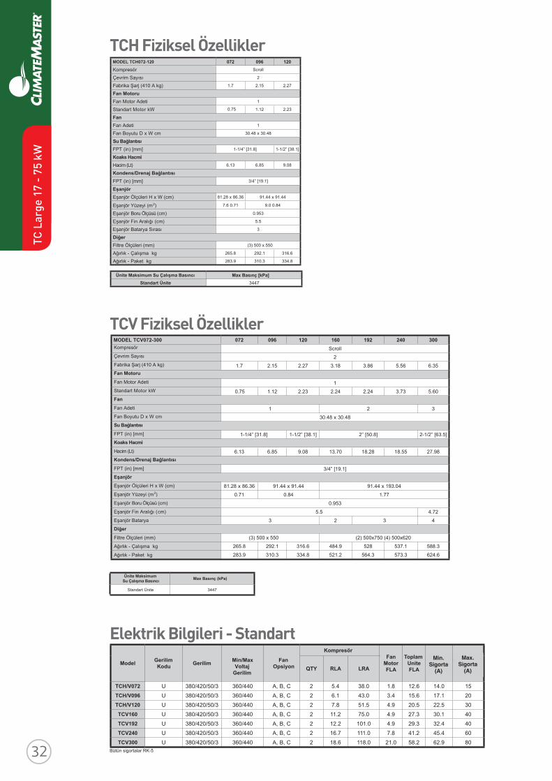
Revised: 8 April, 2016
ClimateMaster works continually to improve its products. As a result, the design and specifi cations of each product at the time of order may be changed without notice and may not be as described herein. Please contact ClimateMaster's Customer Service Department at 1-405-745-6000 for specifi c information on the current design and specifi cations. Statements and other information contained herein are not express warranties and do not form the basis of any bargainbetween the parties, but are merely ClimateMaster's opinion or commendation of its products. The latest version of this document is available at climatemaster.com.
Page ______ of ______LC406 - 25
TC Series 50Hz - HFC410A Submittal Data Eng/S-I
TC - Vertical Upfl ow - Dimensional Data
VerticalModel
Discharge ConnectionDuct Flange Installed (+/- 2.5mm)
Return ConnectionUsing Return Air Opening
M NO
SupplyWidth
PSupplyDepth
Q RS
ReturnDepth
TReturnHeight
U
006 - 012 cm 22.7 12.9 22.9 22.9 14.0 5.3 41.1 25.1 1.9
015 - 030 cm 16.1 9.5 35.6 35.6 13.6 5.8 46.5 53.1 1.9
036 - 042 cm 16.1 9.5 35.6 35.6 13.1 5.8 57.9 60.7 1.9
048 - 060 cm 17.4 18.4 40.6 45.7 13.1 5.8 74.4 57.0 1.9
Access Panels
Top View-Left Return
U
RS IsometricView
Left Return Left View- Air Coil Opening
T
CPower Supply
3/4" [19.1 mm] HVKnockout
Low Voltage1/2" [12.7 mm] LV
KnockoutLow Voltage
1/2" [12.7 mm] LVKnockout
Condensate3/4" IPT
Front-View
K
1.00 [25.4 mm]
F
J HD
L
Air Coil
Field InstalledDischarge Flange
FrontBack
U
R S
T
C
BackFront
Right Return Right View- Air Coil Opening
BSP
CCP
Filter Rail
ASP
Air Coil
Fron
t
NB
P
AO
M
3
2
1
E
I
G
Top View-Right Return
Front
P N
O
Q
ASP
CCP
ASPASP
ASP
Air Coil
Air Coil Side
BSP
Air Coil Side
Units shipped with filter rails. These rails should be removed for return duct connection. See Aff---- for accessory air filter frame with duct collar.
003042291061021690270003-270VCT LEDOMScroll
2
1.7 2.15 2.27 3.18 3.86 5.56 6.35
1
06.537.342.242.232.221.1570.
321
84.03 x 84.03
]5.36[ ”2/1-2]8.05[ ”2]1.83[ ”2/1-1]8.13[ ”4/1-1
89.7255.8182.8107.3180.958.631.6
3/4” [19.1]
40.391 x 44.1944.19 x 44.1963.68 x 82.18
77.148.017.0
0.953
27.45.5
4323
(3) 500 x 550 (2) 500x750 (4) 500x620
3.8851.7358259.4846.6131.2928.562
6.4263.3753.4652.1258.4333.0139.382
Ünite MaksimumSu Çalışma Basıncı Max Basınç (kPa)
7443 Standart Ünite
MODEL TCH072-120 072 096 120
Kompresör Scroll
Çevrim Sayısı 2
Fabrika Şarj (410 A kg) 1.7 2.15 2.27
Fan MotoruFan Motor Adeti 1
Standart Motor kW 1.12 2.23
FanFan Adeti 1
Fan Boyutu D x W cm 30.48 x 30.48
Su BağlantısıFPT (in) [mm] 1-1/4” [31.8] 1-1/2” [38.1]
Koaks HacmiHacim (Lt) 6.13 6.85 9.08
Kondens/Drenaj BağlantısıFPT (in) [mm] 3/4” [19.1]
EşanjörEşanjör Ölçüleri H x W (cm) 81.28 x 86.36 91.44 x 91.44
Eşanjör Yüzeyi (m2) 7.6 0.71 9.0 0.84
Eşanjör Boru Ölçüsü (cm) 0.953
Eşanjör Fin Aralığı (cm) 5.5
Eşanjör Batarya Sırası 3
DiğerFiltre Ölçüleri (mm) (3) 500 x 550
Ağırlık - Çalışma kg 265.8 292.1 316.6
Ağırlık - Paket kg 283.9 310.3 334.8
Ünite Maksimum Su Çalışma Basıncı Max Basınç [kPa]Standart Ünite 3447
Elektrik Bilgileri - Standart
Bütün sigortalar RK-5
Model GerilimKodu Gerilim Min/Max
VoltajGerilim
FanOpsiyon
KompresörFan
MotorFLA
Toplam UniteFLA
MinDevre
Amperi
Max sigortaKapasitesi
HACRQTY RLA LRA
TCH/V072 U 380/420/50/3 360/440 A, B, C 2 5.4 38.0 1.8 12.6 14.0 15TCH/V096 U 380/420/50/3 360/440 A, B, C 2 6.1 43.0 3.4 15.6 17.1 20TCH/V120 U 380/420/50/3 360/440 A, B, C 2 7.8 51.5 4.9 20.5 22.5 30TCV160 U 380/420/50/3 360/440 A, B, C 2 11.2 75.0 4.9 27.3 30.1 40TCV192 U 380/420/50/3 360/440 A, B, C 2 12.2 101.0 4.9 29.3 32.4 40TCV240 U 380/420/50/3 360/440 A, B, C 2 16.7 111.0 7.8 41.2 45.4 60TCV300 U 380/420/50/3 360/440 A, B, C 2 18.6 118.0 21.0 58.2 62.9 80
TCH Fiziksel Özellikler
TCV Fiziksel ÖzelliklerKompresör
Çevrim Sayısı
Fabrika Şarj (410 A kg)
Fan Motoru
Fan Motor Adeti
Standart Motor kW
Fan
Fan Adeti
Fan Boyutu D x W cm
Su Bağlantısı
FPT (in) [mm]
Koaks Hacmi
Hacim (Lt)
Kondens/Drenaj Bağlantısı
FPT (in) [mm]
Eşanjör
Eşanjör Ölçüleri H x W (cm)
Eşanjör Yüzeyi (m2)
Eşanjör Boru Ölçüsü (cm)
Eşanjör Fin Aralığı (cm)
Eşanjör Batarya
Diğer
Filtre Ölçüleri (mm)
Ağırlık - Çalışma kg
Ağırlık - Paket kg
Min.Sigorta
(A)
Max.Sigorta
(A)
0.75
TC L
arge
17
- 75
kW
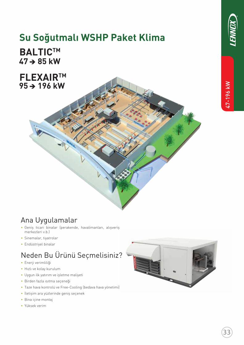
47-1
96 k
W
FLEXAIRTM
Ana Uygulamalar• Geniş ticari binalar (perakende, havalimanları, alışveriş
merkezleri v.b.)
• Sinemalar, tiyatrolar
• Endüstriyel binalar
Neden Bu Ürünü Seçmelisiniz?• Enerji verimliliği
• Hızlı ve kolay kurulum
• Uygun ilk yatırım ve işletme maliyeti
• Birden fazla ısıtma seçeneği
• Taze hava kontrolü ve Free-Cooling (bedava hava yönetimi)
• İletişim ara yüzlerinde geniş seçenek
• Bina içine montaj
• Yüksek verim
Su Soğutmalı WSHP Paket KlimaBALTICTM
47 85 kW
95 196 kW
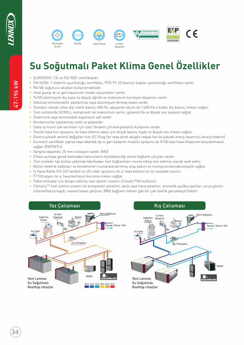
47-1
96 k
W
Su Soğutmalı Paket Klima Genel Özellikler EUROVENT, CE ve ISO 9001 sertifikalıdır. EN 60204-1 elektrik uyumluluğu sertifikası, PED 97-23 basınçlı kaplar uyumluluğu sertifikası vardır. R410A soğutucu akışkan kullanılmaktadır. Heat pump ve ısı geri kazanımlı model seçenekleri vardır. %100 alüminyum dış kasa ile düşük ağırlık ve maksimum korozyon dayanımı vardır. Sökülüp temizlenebilir paslanmaz veya alüminyum direnaj tavası vardır. Standart olarak cihaz dışı statik basınç 600 Pa, opsiyonel seçim ile 1,600 Pa’a kadar dış basınç imkanı sağlar. Tüm ünitelerde SCROLL kompresör ile maksimum verim, güvenilirlik ve düşük ses seviyesi sağlar. Elektronik veya termostatik expansion valf vardır. Kondenserler paslanmaz çelik ve plakalıdır. Daha iyi kısmi yük verimleri için özel Tandem çift kompresörlü kullanımı vardır. Düşük hava hızı opsiyonu ile hava üfleme odası için düşük basınç kaybı ve düşük ses imkanı sağlar. Ekstra yüksek verimli değişken hızlı EC Plug fan veya direk akuple radyal fan ile yüksek enerji tasarrufu (enerji+bakım) Eurovent sertifikalı çapraz veya tekerlek tip ısı geri kazanım modülü opsiyonu ile %100 taze hava ihtiyacının karşılanmasını
sağlar. (PATENTLİ) Yangına dayanıklı 25 mm izolasyon vardır. (MO) Cihazı açmaya gerek kalmadan basınçların ölçülebileceği servis bağlantı çıkışları vardır. Tüm üniteler tak kullan şeklinde fabrikadan tüm bağlantıları monte edilip test edilmiş olarak sevk edilir. Bütün elektrik kabloları ve konektörleri numaralandırılmış olup bakım ve montaj esnasında kolaylık sağlar. İç Hava Kalite Kiti (UV lamba) ve çift cidar opsiyonu ile iç hava kalitesi en iyi seviyede tutulur. F7 filtrasyon ile iç hava kalitesini koruma imkanı sağlar. Paket klimalar için dizayn edilmiş özel işletim sistemi Climatic™60 kullanılır. ClimaticTM özel işletim sistemi ile kompresör yönetimi, akıllı taze hava yönetimi, otomatik yaz/kış ayarları, arıza görün-
tüleme/hafıza kaydı, master/slave çalışma, BMS bağlantı imkanı gibi bir çok özellik gerçekleştirilebilir.
Yaz Çalışması Kış Çalışması
Yeni LennoxSu SoğutmalıRooftop cihazlar
SoğutmaKulesi
SoğutmaKulesi
Su TankıSu Tankı
WSHP
WSHP
Isı Geri Kazanım
Isı Geri Kazanım
Boyler
BoylerKuru SoğutucuKuru Soğutucu
Su PompalarıSu Pompaları
Toprak / Deniz / GölToprak / Deniz / Göl
Yeni LennoxSu SoğutmalıRooftop cihazlar
HermetikScroll
Heat Pump Isı GeriKazanım
R410A
R410A
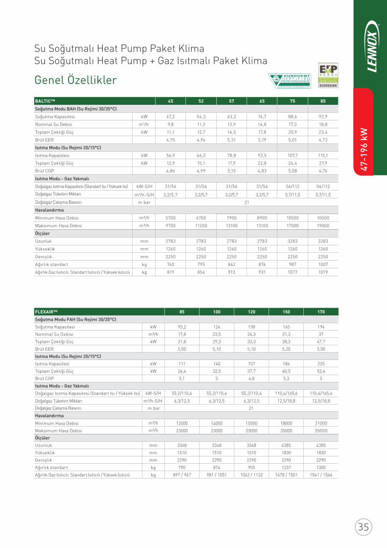
Su Soğutmalı Heat Pump Paket KlimaSu Soğutmalı Heat Pump + Gaz Isıtmalı Paket Klima
Genel Özellikler
47-1
96 k
W
3,2/5,7 3,2/5,7 3,2/5,7 3,2/5,7 5,7/11,5 5,7/11,5
m bar 21
m3/h-S/H
BALTIC™ 45 52 57 65 75 85
Soğutma Modu BAH (Su Rejimi 30/35°C)
Soğutma Kapasitesi kW 47,2 54,3 63,2 74,7 88,6 92,9
Nominal Su Debisi m3/h 9,8 11,2 12,9 14,8 17,3 18,8
Toplam Çektiği Güç kW 11,1 12,7 14,5 17,8 20,9 23,4
Brüt EER 4,75 4,94 5,31 5,19 5,01 4,73
Isıtma Modu (Su Rejimi 20/15°C)
Isıtma Kapasitesi kW 56,9 66,3 78,8 93,5 107,7 115,1
Toplam Çektiği Güç kW 12,9 15,1 17,9 22,8 24,4 27,9
Brüt COP 4,86 4,99 5,15 4,83 5,08 4,76
Isıtma Modu - Gaz Yakmalı
Doğalgaz Isıtma Kapasitesi (Standart Isı / Yüksek Isı)
Doğalgaz Tüketim Miktarı
Doğalgaz Çalışma Basıncı
kW-S/H 31/56
Havalandırma
m³/hMinimum Hava Debisi
m³/h
5700 6700 7900 8900 10500 10500
Maksimum Hava Debisi 9700 11200 13100 13100 17000 19000
Ölçüler
Uzunluk mm 2783 2783 2783 2783 3283 3283
Yükseklik mm 1260 1260 1260 1260 1260 1260
Genişlik mm 2250 2250 2250 2250 2250 2250
Ağırlık standart kg 760 795 842 876 987 1007
Ağırlık Gaz Isıtıcılı Standart Isıtıcılı / Yüksek Isıtıcılı kg 819 854 913 931 1077 1079
FLEXAIR™ 85 100 120 150 170
Soğutma Modu FAH (Su Rejimi 30/35°C)
Soğutma Kapasitesi kW 93,2 124 138 165 194
Nominal Su Debisi m³/h 17,8 23,5 26,3 31,3 37
Toplam Çektiği Güç kW 21,8 29,3 33,3 38,3 47,7
Brüt EER 5,00 5,10 5,10 5,20 5,00
Isıtma Modu (Su Rejimi 20/15°C)
Isıtma Kapasitesi kW 111 140 157 186 225
Toplam Çektiği Güç kW 24,4 32,5 37,7 40,5 52,4
Brüt COP 5,1 5 4,8 5,3 5
Isıtma Modu - Gaz Yakmalı
Doğalgaz Isıtma Kapasitesi (Standart Isı / Yüksek Isı) kW-S/H 55,2/110,4 55,2/110,4 55,2/110,4 110,4/165,6 110,4/165,6
Doğalgaz Tüketim Miktarı 6,3/12,5 6,3/12,5 6,3/12,5 12,5/18,8 12,5/18,8
Havalandırma
m³/hMinimum Hava Debisim³/h
12000 14000 15000 18000 21000
Maksimum Hava Debisi 23000 23000 23000 35000 35000Ölçüler
Uzunluk mm 3348 3348 3348 4385 4385
Yükseklik mm 1510 1510 1510 1830 1830
Genişlik mm 2290 2290 2290 2290 2290
Ağırlık standart kg 790 874 955 1237 1300
Ağırlık Gaz Isıtıcılı Standart Isıtıcılı / Yüksek Isıtıcılı kg 897 / 967 981 / 1051 1062 / 1132 1478 / 1501 1541 / 1564
m3/h-S/H
31/56 31/56 31/56 56/112 56/112
m bar 21Doğalgaz Çalışma Basıncı
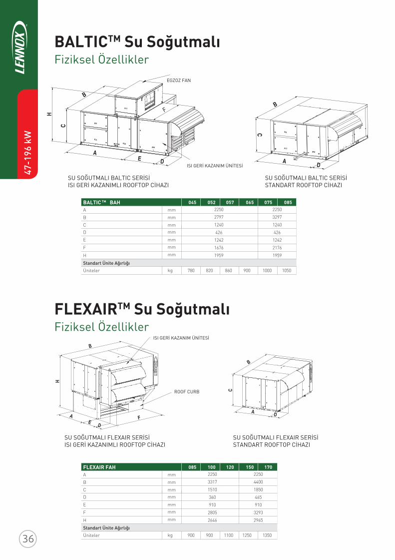
47-1
96 k
W
Fiziksel Özellikler
Fiziksel Özellikler
BALTICTM Su Soğutmalı
FLEXAIRTM Su Soğutmalı
SU SOĞUTMALI BALTIC SERİSİISI GERİ KAZANIMLI ROOFTOP CİHAZI
SU SOĞUTMALI BALTIC SERİSİ STANDART ROOFTOP CİHAZI
SU SOĞUTMALI FLEXAIR SERİSİISI GERİ KAZANIMLI ROOFTOP CİHAZI
SU SOĞUTMALI FLEXAIR SERİSİ STANDART ROOFTOP CİHAZI
ISI GERİ KAZANIM ÜNİTESİ
ROOF CURB
BALTIC TM BAH 045 052 057 065 075 085
A mm
B mm
CD
E
F
H
Üniteler
mm mm
mm mm
mm
kgStandart Ünite Ağırlığı
2250
2797
1240
426
1242
1676
1959
780 820 860 900 1000 1050
2250
3297
1240
426
1242
2176
1959
FLEXAIR FAH 085 100 120 150 170
A mm
B mm
CD
E
F
H
Üniteler
mm mm
mm mm
mm
kgStandart Ünite Ağırlığı
2250
3317
1510
360
910
2805
2646
900 900 1100 1250 1350
2250
4400
1850
465
910
3293
2965
ISI GERİ KAZANIM ÜNİTESİ
EGZOZ FAN
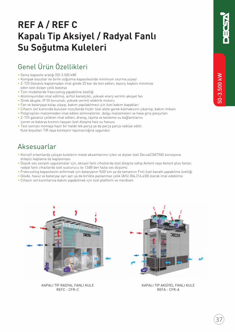
REF A / REF C Kapalı Tip Aksiyel / Radyal Fanlı Su Soğutma Kuleleri
• Geniş kapasite aralığı (50-3.500 kW)• Kompak boyutlar ile birim soğutma kapasitesinde minimum oturma yüzeyi• Z-725 Galvaniz kaplamadan imal gövde 25 bar da test edilen, basınç kaybını minimize eden özel dizayn çelik batarya • Tüm modellerde freecooling yapabilme özelliği • Alüminyumdan imal edilmiş, airfoil kanatçıklı, yüksek enerji verimli aksiyel fan• Direk akuple, IP 55 korumalı, yüksek verimli elektrik motoru• Fan ve bataryaya kolay ulaşıp, bakım yapılabilmesi için özel bakım kapakları• Cihazın üst kısmında bulunan nozullarda hiçbir özel alete gerek kalmaksızın çıkarılıp, bakım imkanı• Polipropilen malzemeden imal edilen eliminatörler, dolgu malzemeleri ve hava giriş panjurları• Z-725 galvaniz çelikten imal edilen, drenaj, taşma ve besleme su bağlantılarını içeren ve batarya kısmını taşıyan özel dizayna haiz su havuzu• Test sonrası montaja hazır bir halde tek parça ya da parça parça nakliye edilir. Kule boyutları TIR veya konteynır taşımacılığına uygundur.
50-3
.500
kW
Genel Ürün Özellikleri
• Korozif ortamlarda çalışan kulelerin metal aksamlarının içten ve dıştan özel DecsaCOATING korozyona önleyici kaplama ile kaplanması• Düşük ses seviyeli uygulamalar için, aksiyel fanlı cihazlarda özel dizayna sahip Axilent veya Axilent plus fanlar, radyal fanlı cihazlarda özel susturucu ile 12dB’den fazla ses düşümü• Freecooling kapasitesini arttırmak için bataryanın %50’sini ya da tamamını Finli özel kanatlı yapabilme özelliği• Gövde, havuz ve bataryayı ayrı ayrı ya da birlikte paslanmaz çelik (AISI 304,316,430) olarak imal edebilme • Cihazın üst kısımlarına bakım yapabilmek için özel platform ve merdiven
Aksesuarlar
KAPALI TİP RADYAL FANLI KULEREFC - CFR-C
KAPALI TİP AKSİYEL FANLI KULEREFA - CFR-A
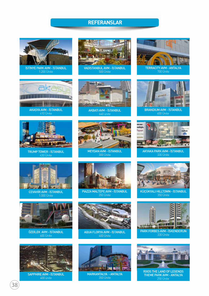
REFERANSLAR
PIAZZA MALTEPE AVM - İSTANBUL350 Ünite
KÜÇÜKYALI HILLTOWN - İSTANBUL350 Ünite
CEVAHİR AVM - İSTANBUL1.000 Ünite
MEYDAN AVM - İSTANBUL300 Ünite
AKYAKA PARK AVM - İSTANBUL330 Ünite
TRUMP TOWER - İSTANBUL430 Ünite
AKBATI AVM - İSTANBUL640 ünite
BRANDIUM AVM - İSTANBUL400 Ünite
AKASYA AVM - İSTANBUL410 Ünite
İSTİNYE PARK AVM - İSTANBUL1.200 Ünite
TERRACITY AVM - ANTALYA700 Ünite
VADİSTANBUL AVM - İSTANBUL500 Ünite
SAPPHIRE AVM - İSTANBUL400 ünite
RIXOS THE LAND OF LEGENDSTHEME PARK AVM - ANTALYA
250 Ünite MARKANTALYA - ANTALYA
350 Ünite
PARK FORBES AVM - İSKENDERUN330 Ünite
AQUA FLORYA AVM - İSTANBUL400 Ünite
ÖZDİLEK AVM - İSTANBUL600 Ünite
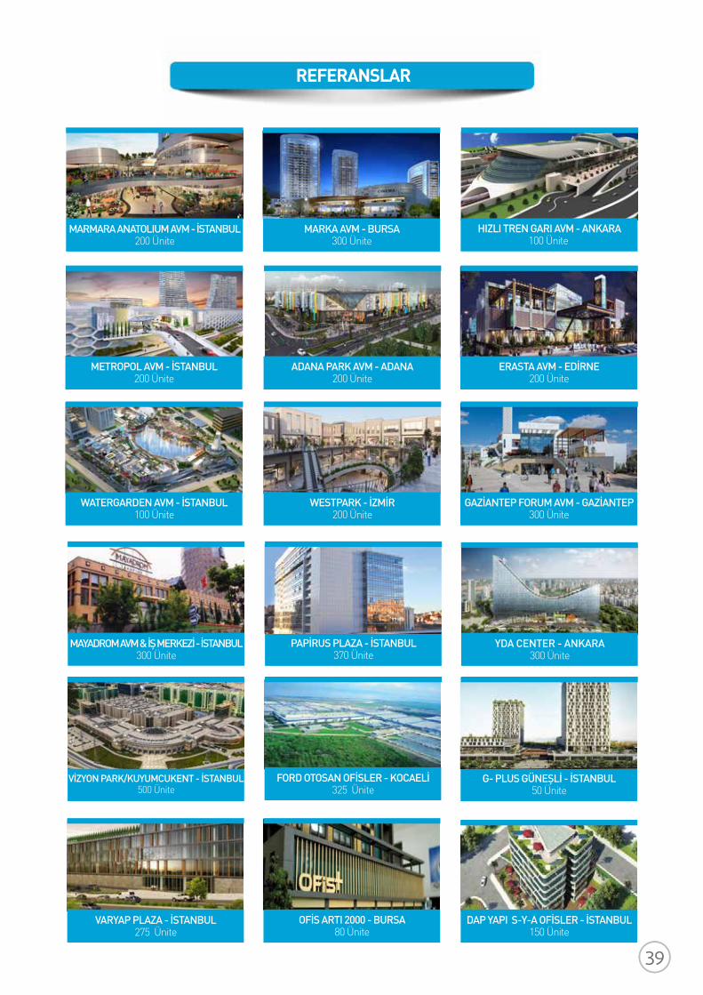
REFERANSLAR
WATERGARDEN AVM - İSTANBUL100 Ünite
MARMARA ANATOLIUM AVM - İSTANBUL200 Ünite
MARKA AVM - BURSA300 Ünite
HIZLI TREN GARI AVM - ANKARA100 Ünite
METROPOL AVM - İSTANBUL200 Ünite
ADANA PARK AVM - ADANA200 Ünite
ERASTA AVM - EDİRNE200 Ünite
WESTPARK - İZMİR200 Ünite
GAZİANTEP FORUM AVM - GAZİANTEP300 Ünite
PAPİRUS PLAZA - İSTANBUL370 Ünite
MAYADROM AVM & İŞ MERKEZİ - İSTANBUL300 Ünite
YDA CENTER - ANKARA300 Ünite
VİZYON PARK/KUYUMCUKENT - İSTANBUL500 Ünite
FORD OTOSAN OFİSLER - KOCAELİ325 Ünite
G- PLUS GÜNEŞLİ - İSTANBUL50 Ünite
VARYAP PLAZA - İSTANBUL275 Ünite
OFİS ARTI 2000 - BURSA80 Ünite
DAP YAPI S-Y-A OFİSLER - İSTANBUL150 Ünite
ÜR
Ü-C
M-2
018-
04
FORM ENDÜSTRİ ÜRÜNLERİ TİC. A.Ş.Eski Büyükdere Cad. Sümer Sokak No:3Ayazağa Ticaret Merkezi Kat:16Maslak 34398 İstanbulT : 0212 286 18 38F : 0212 286 66 48E : [email protected] : www.formgroup.com
BÖLGE MÜDÜRLÜKLERİAdana : 0322 881 00 11Ankara : 0312 220 10 30Antalya : 0242 317 11 20Bursa : 0224 249 95 26İzmir : 0232 459 02 70
FORM ENDÜSTRİ ÜRÜNLERİ Form Endüstri Ürünleri firmasının ana faaliyet alanı Klima sistemleri konusunda temsilcilik, satış ve satış sonrası hizmetlerdir. Konularında dünya lideri olan firmalardan oluşan marka temsilcilikleri bulunmaktadır. Özellikle yüksek enerji verimliliği içeren ve çevre dostu olan sistem çözümleri konusunda geniş bir tecrübeye ve çok sayıda uygulamaya sahiptir.
1965 yılında Ankara’da kurularak çalışmalarına başlayan Form Şirketler Grubu, iklimlendirme ve endüstriyel sistemler alanında, yaşam ve imalat kalitesini arttıracak cihazların üretim ve temini ile birlikte düzenli bakımını sağlamaktadır. Yüksek enerji verimliliği ve çevre dostu sistem çözümleri
sunan Form Şirketler Grubu, sektörde ve hizmet verdiği alanlarda etik değerlere bağlı, güvenilir velider firmalardan biri olmaya devam etmektedir.


