TWELFTH ANNUAL CONFERENCE ON CARBON CAPTURE, UTILIZATION AND SEQUESTRATION MAY 13‐16, 2013 • DAVID L. Lawrence Convention Center • Pittsburgh, Pennsylvania Page1
Reservoir Simulation of CO2 Sequestration in Deep Saline
Reservoir, Citronelle Dome, USA
S.Alireza Haghighat1, Shahab D. Mohaghegh1, Najmeh Borzouei2, Daniel Moreno1, Alireza
Shahkarami1; 1:West Virginia University, 2: Shell Exploration and Production Co
Abstract: CCS (Carbon Capture and Storage) is a fast growing method for mitigation of CO2 emissions. Carbon storage in underground geological formations is one of the applicable approaches of CCS. The main concern for a geologic carbon dioxide (CO2) sequestration is sustained confinement of the injected CO2 over long time periods (hundreds of years). For selection of the proper underground storage site, monitoring the CO2 plume movement and predicting the behavior of the reservoir pressure (indicator of potential leakage in the system), it is essential to use an appropriate multiphase flow dynamic reservoir model. The Numerical Reservoir Simulator is the most appropriate tool for accomplishing this task. Data collected from an ongoing saline storage pilot, Citronelle Dome, located in Mobile County (Alabama, US), was considered for this study. This project is a part of a CO2 storage research project funded by the U.S. Department of Energy (DOE) and conducted by the Southeast Regional Carbon Sequestration Partnership, which is primarily comprised of the Southern States Energy Board, Electric Power Research Institute, Southern Company, Advanced Resources International and Denbury Offshore, to demonstrate commercial-scale storage of CO2 captured from an existing coal-fired power plant. A commercial reservoir simulation model (CMG’s GEM) for CO2 sequestration at the Citronelle Dome was developed. The model is based on a comprehensive geological study that included data from more than 40 well logs. The presence of PDGs (Pressure Down-hole Gauge) was considered in the reservoir model at the observation well. Relative permeability curves, hysteresis, rock type, vertical permeability, boundary condition and brine density as well as compressibility are several uncertain variables for multiple reservoir simulations and parametric studies. 500 years is the time frame of interest for assessing the effect of each parameter (within a typical range) on the CO2 plume extension and reservoir pressure behavior (in observation well). The results are analyzed to investigate the uncertainty of CO2 behavior and risk of leakage. Also this analysis provides a framework to be used for history matching the reservoir model in presence of actual field data (real time pressure from observation well). Introduction
It has been documented that the biggest source of global CO2 emissions is the combustion of fossil fuels. This emission is one of the main causes of climate change with serious impacts on a variety of issues. It seems to be widely accepted that a comprehensive switch from fossil fuels to green fuels will take several decades to be completed; other CO2 emission mitigation options like CCS (Carbon Capture and Storage) must be implemented to bridge the gap. There are different potential sites for geological CO2 sequestration such as: depleted oil and gas reservoirs, deep saline reservoirs, deep un-mineable coal seams, and storage in association with
TWELFTH ANNUAL CONFERENCE ON CARBON CAPTURE, UTILIZATION AND SEQUESTRATION MAY 13‐16, 2013 • DAVID L. Lawrence Convention Center • Pittsburgh, Pennsylvania Page2
CO2/EOR. Deep saline reservoirs are estimated to have enough volumetric capacity to sequester enormous amount of CO2. Despite the limited locations of oil and gas reservoirs, deep saline formations are wide spread geographically, providing more chances to store CO2 from many emission sources [2]. Based on predictions, the retention time for CO2 to be stored in saline reservoir can be up to thousands of years, representing the best storability amongst the other geological options [2]. Geological storage of CO2 is associated with different type of potential risks, such as leakage of CO2 or brine from the target zone. This risk can be managed with careful site selection, with an emphasis on well integrity, reservoir modeling, appropriate monitoring, and the establishment of a remediation strategy [5]. For long term CO2 storage, it is necessary for the target reservoir to be sealed by an impervious cap rock. Under some unfavorable conditions, the integrity of the cap rock can be damaged by improperly cemented wells, unsealed faults, high permeable regions, and fractures. In order to quantify the risk of CO2 leakage, it is necessary to determine CO2 plume extension to see if the injected CO2 reaches and contacts existing leakage pathways. Additionally, CO2 injection into saline reservoirs generates pressure build up (which might go much further than the CO2 plume), resulting in a higher risk of seal integrity damage (creating fractures or activating faults) and displacement of brine into the underground drinking water sources. Therefore, determining the magnitude and location of pressure build up in the reservoir is extremely important for operators and regulators to evaluate the pressure induced risks. In this work, we study and model CO2 injection in a deep saline reservoir (Citronelle Dome, Alabama) with a conventional reservoir simulator (CMG’s GEM). The main objective is to focus on reservoir pressure build up and CO2 plume extension behavior subject to variation of uncertain reservoir parameters (sensitivity analysis). The results of the sensitivity analysis can be used in CO2 injection risk assessment. Site Description
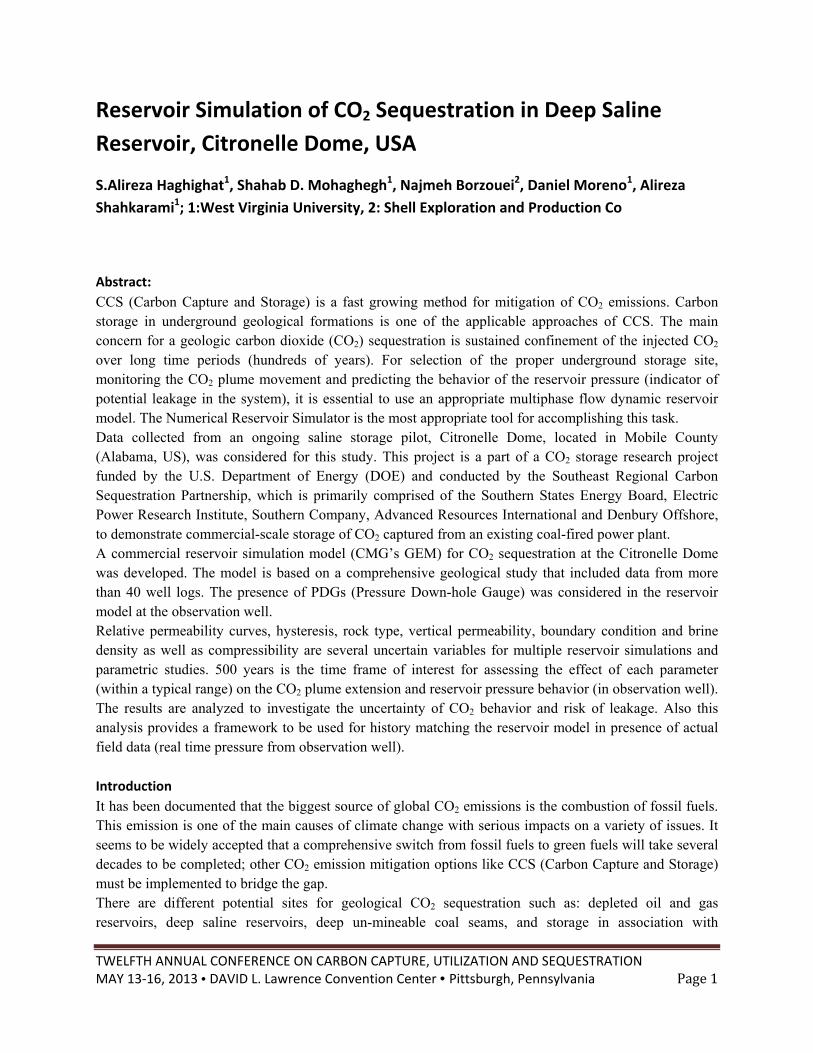
Injection and storage of CO2 in Citronelle, AL is the third phase of Southeastern Regional Carbon Sequestration Partnership. It aims to demonstrate commercial-scale storage of CO2 captured from an existing coal-fired power plant. Alabama Power Company's Plant Barry is the source of the CO2, which is approximately 12 miles from the Anthropogenic Test Site (located within Denbury Onshore’s Southeast Citronelle operating unit). The project will be capable of capturing approximately 185,000 tons of anthropogenic CO2 per year. A pipeline was constructed from Plant Barry to the test site (Figure 1.a), and the CO2 is injected into saline Paluxy sandstones at depths of approximately 9,500 feet. Injection is planned to continue for three years and at the end of injection, the sequestered CO2 will be monitored for an additional four years in order to determine how well the CO2 has been contained. The Paluxy formation (proposed injection zone) is located at a depth of about 9,450 to 10,500ft (TVD). This formation represents a coarsening-upward succession of variegated shale and sandstone [3]. Based on the logs from the injection well, twenty seven individual sandstones in the Paluxy formation were identified as potential storage reservoirs for CO2. Ten sand layers that are the thickest and most extensive, were selected for injection. Citronelle Dome, a broad, gently dipping salt pillow, provides the Citronelle Field with structural closure at all stratigraphic horizons of the Jurassic through Tertiary age, including the Paluxy formation. Moreover, there is an apparent lack of faulting at the Citronelle Dome structure [3]. The proposed confining zone for this CO2 injection test is the basal shale of the Washita-Fredericksburg interval, which has an average thickness of 150 ft. (Figure 1.b). The aquifers on top and bottom of this confining unit (including the Paluxy) represent extremely low groundwater velocities [3].
TWELFTH ANNUAL CONFERENCE ON CARBON CAPTURE, UTILIZATION AND SEQUESTRATION MAY 13‐16, 2013 • DAVID L. Lawrence Convention Center • Pittsburgh, Pennsylvania Page3
Figure 1:( a) Location of power plant and injection well (b): Stratigraphic layers in the Citronelle Dome [3]
Reservoir Simulation Model
Based upon interpretation and evaluation of geophysical well logs, a comprehensive picture of the subsurface geology has been developed for the reservoir simulation modeling. The reservoir models were built in the Computer Modeling Group’s (CMG) numerical simulation software. The geological structure of the model includes 17 sand layers representing 51 simulation layers. A Cartesian grid has been used with a dimension of 150*150*51 grid cells (∆x and ∆y equal to 133 ft). Well logs from 40 offset wells that are within the area of study have been acquired and interpreted in order to generate porosity maps. Also, porosity-permeability cross plots that were obtained from core analysis provide reasonable estimates for the permeability distribution within the reservoir. Relative permeability curves from the history-match of the injection pilot test at the Mississippi Test Site were used in this simulation (trapped gas saturation was considered value of 7.5 percent). Other reservoir properties are summarized in Table 1. This is considered as a base case model in the following sections.
Table 1: Reservoir parameters and properties (base case model)
Parameter Value Parameter Value
Permeability(md) 0.824 . Water density(lb/ft3) 62 Temperature(◦F) 230 Water viscosity(cp) 0.26
Salinity(ppm) 100000 Water compressibility(1/psi) 3.2E-6
Residual gas saturation 0.35 Kv/Kh(permeability ratio) 0.1
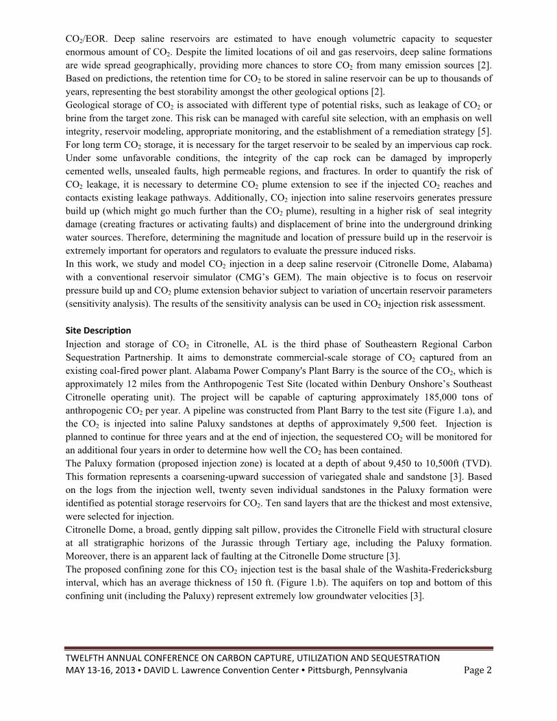
Residual water saturation 0.6 Pressure reference@9415ft(psi) 4393 For the reservoir simulation, the injection well was operated with maximum bottom-hole pressure limit of 6,300 psi and injection rate constraint of 9.45 million standard cubic feet per day. The injection starts at the beginning of 2012 and takes 3 years. For post-injection site care analysis, the simulation run goes over 500 years. Based on the initial studies, maximum CO2 plume extension occurs in the top and sixth layer. The plume area has the approximate major diameter of 4,933 ft, 500 years after the injection (Figure 2).
TWELFTHMAY 13‐1
Figure 2: Plu
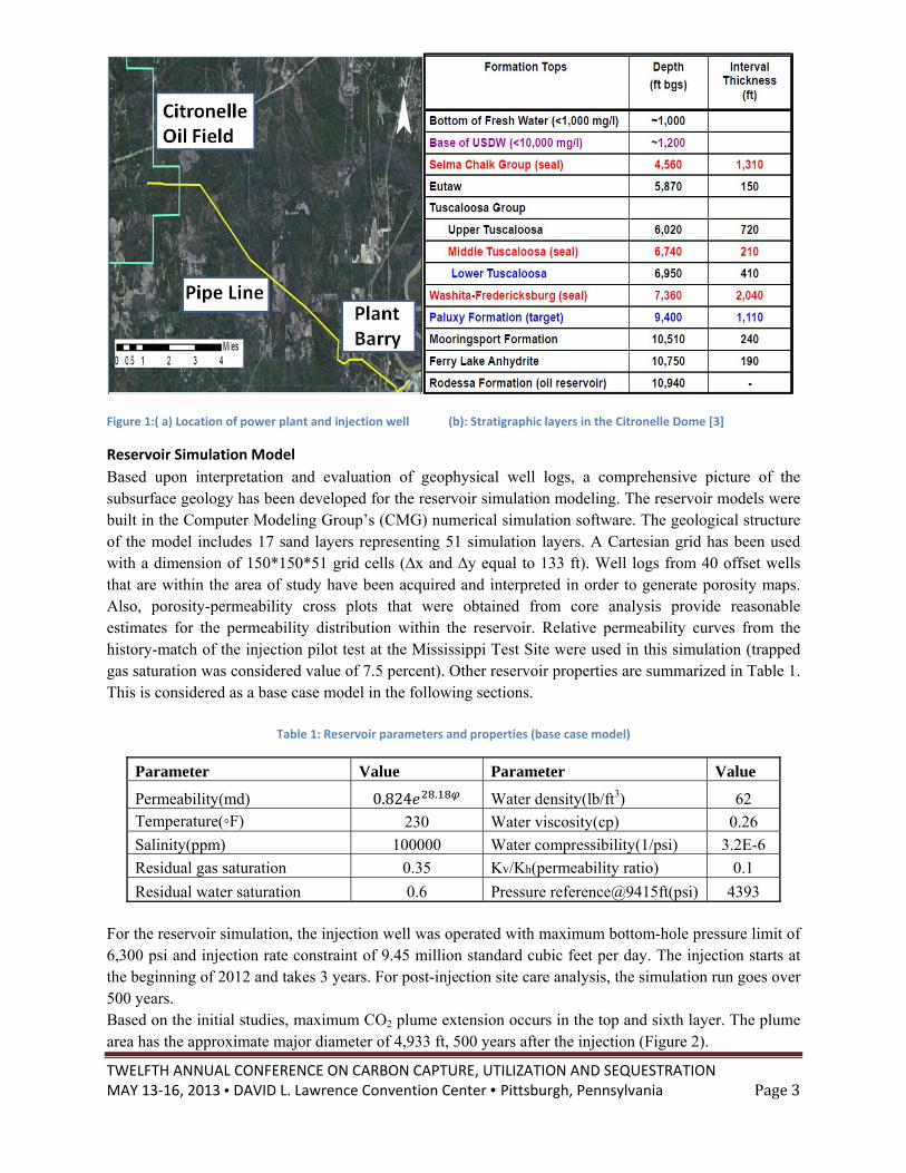
Two Presis locatedtemperatuleakage dthe reservPDG in t“maximumpressure din the obsyears (Fig
Sensitivity
In this sepropertiesuncertaintwell) and (rock typepermeabilshape is e
Major
ANNUAL CO16, 2013 • DAV
ume extension i
sure Down-hd 820 ft at theure measuremdetection) in avoir simulatiothe observatiom pressure) ddecreases graservation welgure 3).
y Analysis
ection, simulas. The sensitty range) to iCO2 plume e
e), gas relativlity ratio, bouelliptical, the m
r Axis
NFERENCE OVID L. Lawren
in the first layer
hole Gauges (e east side of
ments. The actaddition to hion pressure beon well. Pres
during the 3 ydually to 4,66ll follows a v
Figure 3: press
ation model tivity analysiinvestigate thextension. Thve permeabilitundary conditimagnitude of
Minor Axis
N CARBON CAnce Conventio
r (left) and all lay
PDG) are insf the injectiotual pressure distory matchinehavior at thessure in the
years injection60 psi after 1
very gentle de
sure behavior in
predictions ais procedure he correspondhe reservoir pty, maximumion, brine comf the major an
APTURE, UTILon Center • P
yers 500 years a
stalled in the n well. Thesdata can be ung. Thereforee grid block tobservation
n period (20121 year (stabiliecline and sta
n the observatio
are presentedwas to cha
ding effects oarameters tha
m residual gas mpressibility,nd minor axis
LIZATION ANDittsburgh, Pe
after injection
project’s obse PDGs can
used for reserve, the main fothat corresponwell rises fr2 to 2015). Aized pressure)able trend fro
on well (base cas
d considering ange one paron the reservoat we analyzesaturation (h
, and density.(Figure 2) ca
D SEQUESTRAnnsylvania
servation wellprovide real
voir monitorinfocus of this snds to the ex
rom 4,400 psAfter the inject
). Finally theom 4,660 to 4
se model)
uncertainty rameter at a oir pressure (ed in this studhysteresis), ve
Since the COan characteriz
ATION P
l (D-9-8#2), wtime pressur
ng (especiallystudy is to an
xact location si to 4,727 ption is stoppe
e reservoir pre4,653 psi ove
in some resetime (withi
(at the observdy are permeaertical to horizO2 plume exteze the underg
Page4
which re and y CO2 nalyze of the
psi (or ed, the essure er 500
ervoir in the vation ability zontal ension ground
TWELFTH ANNUAL CONFERENCE ON CARBON CAPTURE, UTILIZATION AND SEQUESTRATION MAY 13‐16, 2013 • DAVID L. Lawrence Convention Center • Pittsburgh, Pennsylvania Page5
CO2 distribution 5, 50 or 500 years after the injection. Additionally, to analyze the reservoir pressure behavior, we focused on maximum (at the end of injection) and stabilized pressures. Permeability
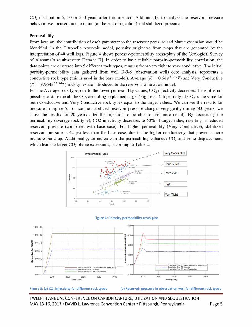
From here on, the contribution of each parameter to the reservoir pressure and plume extension would be identified. In the Citronelle reservoir model, porosity originates from maps that are generated by the interpretation of 40 well logs. Figure 4 shows porosity-permeability cross-plots of the Geological Survey of Alabama’s southwestern Dataset [3]. In order to have reliable porosity-permeability correlation, the data points are clustered into 5 different rock types, ranging from very tight to very conductive. The initial porosity-permeability data gathered from well D-9-8 (observation well) core analysis, represents a conductive rock type (this is used in the base model). Average ( 0.64 . ) and Very Conductive ( 9.964 . ) rock types are introduced to the reservoir simulation model. For the Average rock type, due to the lower permeability values, CO2 injectivity decreases. Thus, it is not possible to store the all the CO2 according to planned target (Figure 5.a). Injectivity of CO2 is the same for both Conductive and Very Conductive rock types equal to the target values. We can see the results for pressure in Figure 5.b (since the stabilized reservoir pressure changes very gently during 500 years, we show the results for 20 years after the injection to be able to see more detail). By decreasing the permeability (average rock type), CO2 injectivity decreases to 60% of target value, resulting in reduced reservoir pressure (compared with base case). For higher permeability (Very Conductive), stabilized reservoir pressure is 42 psi less than the base case, due to the higher conductivity that prevents more pressure build up. Additionally, an increase in the permeability enhances CO2 and brine displacement, which leads to larger CO2 plume extensions, according to Table 2.
Figure 4: Porosity‐permeability cross‐plot
Figure 5: (a) CO2 injectivity for different rock types (b) Reservoir pressure in observation well for different rock types
TWELFTH ANNUAL CONFERENCE ON CARBON CAPTURE, UTILIZATION AND SEQUESTRATION MAY 13‐16, 2013 • DAVID L. Lawrence Convention Center • Pittsburgh, Pennsylvania Page6
Table 2:CO2 Plume extension size over time (in the first layer) for different rock types
Permeability
Base Case (K=0.824e^28.18 φ)
Average (K=0.64e^21.87 φ)
Very Conductive (K=9.964e^21.74φ)
CO2 Plume Extension
5 Years after Injection
Minor Axis(ft) 2133 1600 2533
Major Axis(ft) 2400 1733 3200
50 Years after Injection
Minor Axis(ft) 2533 1867 2800
Major Axis(ft) 4000 2133 4667
500 Years after Injection
Minor Axis(ft) 2667 2133 2667
Major Axis(ft) 4933 3733 5067
Vertical permeability
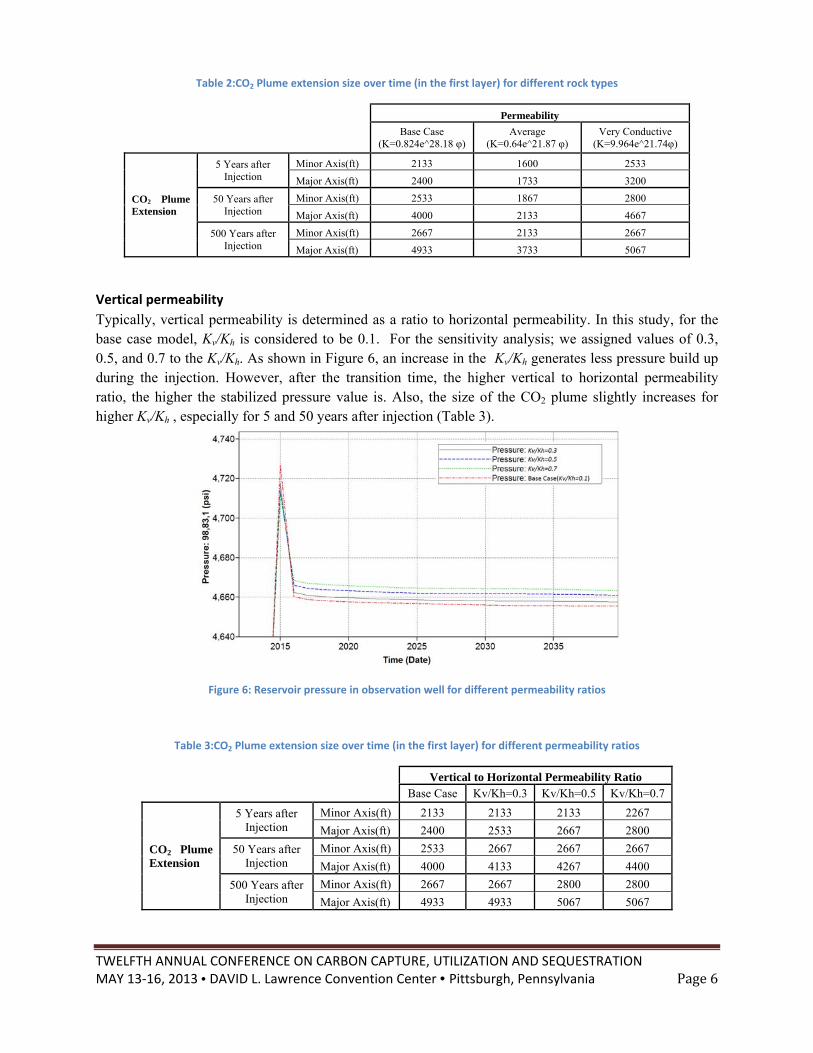
Typically, vertical permeability is determined as a ratio to horizontal permeability. In this study, for the base case model, Kv/Kh is considered to be 0.1. For the sensitivity analysis; we assigned values of 0.3, 0.5, and 0.7 to the Kv/Kh. As shown in Figure 6, an increase in the Kv/Kh generates less pressure build up during the injection. However, after the transition time, the higher vertical to horizontal permeability ratio, the higher the stabilized pressure value is. Also, the size of the CO2 plume slightly increases for higher Kv/Kh , especially for 5 and 50 years after injection (Table 3).
Figure 6: Reservoir pressure in observation well for different permeability ratios
Table 3:CO2 Plume extension size over time (in the first layer) for different permeability ratios
Vertical to Horizontal Permeability Ratio
Base Case Kv/Kh=0.3 Kv/Kh=0.5 Kv/Kh=0.7
CO2 Plume Extension
5 Years after Injection
Minor Axis(ft) 2133 2133 2133 2267
Major Axis(ft) 2400 2533 2667 2800
50 Years after Injection
Minor Axis(ft) 2533 2667 2667 2667
Major Axis(ft) 4000 4133 4267 4400
500 Years after Injection
Minor Axis(ft) 2667 2667 2800 2800
Major Axis(ft) 4933 4933 5067 5067
TWELFTHMAY 13‐1
Gas Relat
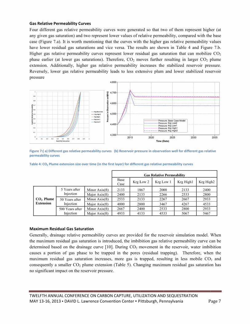
Four diffeany givencase (Figuhave loweHigher gaphase earextensionReverselypressure
Figure 7:( a)permeabilit
Table 4: CO
CO2 PlExtensi
Maximum
Generallythe maximdeterminecauses a maximumconsequenno signifi
ANNUAL CO16, 2013 • DAV
tive Permeab
erent gas relan gas saturatioure 7.a). It is er residual gas relative perlier (at lowe. Additionall
y, lower gas
) Different gas rty curves
2 Plume extensi
lume ion
5 YearInjec
50 YeaInjec
500 YeaInjec
m Residual Ga
y, drainage remum residualed based on tportion of g
m residual gantly a smallercant impact o
NFERENCE OVID L. Lawren
ility Curves
ative permeabon) and two re
worth mentias saturationermeability cuer gas saturatly, higher garelative perm
relative permeab
ion size over tim
rs after ction
MinoMajo
ars after ction
MinoMajo
ars after ction
MinoMajo
as Saturation
elative permeagas saturatio
the drainage gas phase to as saturation r CO2 plume
on the reservo
N CARBON CAnce Conventio
bility curves epresent loweoning that ths and vice vurves represetions). Therefas relative p
meability lead
bility curves (b
me (in the first la
or Axis(ft) or Axis(ft) or Axis(ft) or Axis(ft) or Axis(ft) or Axis(ft)
n
ability curveson is introduccurve [10]. Dbe trappedincreases, mextension (T
oir pressure.
APTURE, UTILon Center • P
were generater values of ree curves withersa. The resent lower resfore, CO2 moermeability i
ds to less ext
b) Reservoir pres
ayer) for differen
Base Case
Krg L
2133 182400 212533 214000 282667 244933 41
s are provideced, the imbibDuring CO2 min the pores
more gas is tTable 5). Cha
LIZATION ANDittsburgh, Pe
ted so that twelative permeh the higher gsults are showsidual gas satoves further increases thetensive plum
ssure in observa
nt gas relative p
Gas Relative
Low 2 Krg L
867 200133 226133 226800 346400 253133 453
d for the resebition gas relamovement in
(residual tratrapped, resu
anging maxim
D SEQUESTRAnnsylvania
wo of them reeability, compgas relative pwn in Table turation that resulting in
e stabilized rand lower s
ation well for dif
permeability cur
e Permeability
Low 1 Krg Hi
00 21366 25367 26667 42633 28033 506
ervoir simulaative permeabthe reservoir
apping). Thulting in lessmum residual
ATION P
epresent highpared with thepermeability v
4 and Figurcan mobilizelarger CO2 p
reservoir prestabilized rese
fferent gas relat
rves
igh1 Krg Hig
3 24003 28007 29337 45330 29337 5467
ation model. Wbility curve cr, water imbi
herefore, whes mobile CO
gas saturatio
Page7
her (at e base values e 7.b. e CO2 plume
essure. ervoir
tive
gh2
When can be bition
en the O2 and on has
TWELFTH ANNUAL CONFERENCE ON CARBON CAPTURE, UTILIZATION AND SEQUESTRATION MAY 13‐16, 2013 • DAVID L. Lawrence Convention Center • Pittsburgh, Pennsylvania Page8
Table 5: CO2 Plume extension size over time (in the first layer) for different maximum residual gas saturations
Maximum Residual Gas Saturation(Hysteresis)
Base Case 0.05 0.1 0.2
CO2 Plume Extension
5 Years after Injection
Minor Axis(ft) 2133 2133 2133 2133 Major Axis(ft) 2400 2400 2400 2400
50 Years after Injection
Minor Axis(ft) 2533 2533 2533 2400 Major Axis(ft) 4000 4000 3867 3733
500 Years after Injection
Minor Axis(ft) 2667 2800 2533 2533 Major Axis(ft) 4933 4933 4800 4533
Brine Compressibility
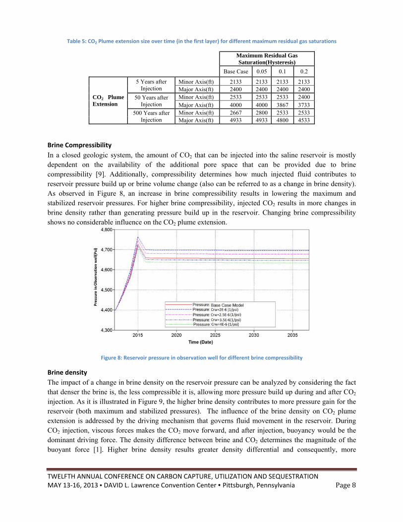
In a closed geologic system, the amount of CO2 that can be injected into the saline reservoir is mostly dependent on the availability of the additional pore space that can be provided due to brine compressibility [9]. Additionally, compressibility determines how much injected fluid contributes to reservoir pressure build up or brine volume change (also can be referred to as a change in brine density). As observed in Figure 8, an increase in brine compressibility results in lowering the maximum and stabilized reservoir pressures. For higher brine compressibility, injected CO2 results in more changes in brine density rather than generating pressure build up in the reservoir. Changing brine compressibility shows no considerable influence on the CO2 plume extension.
Figure 8: Reservoir pressure in observation well for different brine compressibility
Brine density
The impact of a change in brine density on the reservoir pressure can be analyzed by considering the fact that denser the brine is, the less compressible it is, allowing more pressure build up during and after CO2 injection. As it is illustrated in Figure 9, the higher brine density contributes to more pressure gain for the reservoir (both maximum and stabilized pressures). The influence of the brine density on CO2 plume extension is addressed by the driving mechanism that governs fluid movement in the reservoir. During CO2 injection, viscous forces makes the CO2 move forward, and after injection, buoyancy would be the dominant driving force. The density difference between brine and CO2 determines the magnitude of the buoyant force [1]. Higher brine density results greater density differential and consequently, more
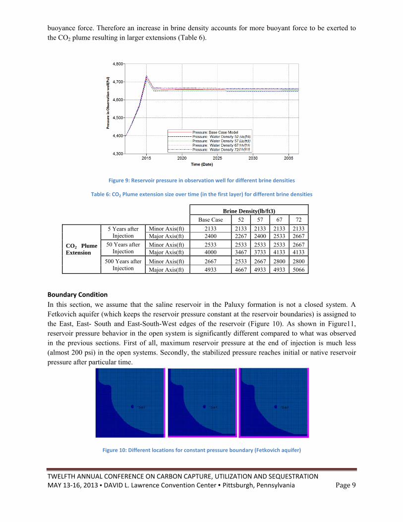
TWELFTH ANNUAL CONFERENCE ON CARBON CAPTURE, UTILIZATION AND SEQUESTRATION MAY 13‐16, 2013 • DAVID L. Lawrence Convention Center • Pittsburgh, Pennsylvania Page9
buoyance force. Therefore an increase in brine density accounts for more buoyant force to be exerted to the CO2 plume resulting in larger extensions (Table 6).
Figure 9: Reservoir pressure in observation well for different brine densities
Table 6: CO2 Plume extension size over time (in the first layer) for different brine densities
Brine Density(lb/ft3)
Base Case 52 57 67 72
CO2 Plume Extension
5 Years after Injection
Minor Axis(ft) 2133 2133 2133 2133 2133 Major Axis(ft) 2400 2267 2400 2533 2667
50 Years after Injection
Minor Axis(ft) 2533 2533 2533 2533 2667 Major Axis(ft) 4000 3467 3733 4133 4133
500 Years after Injection
Minor Axis(ft) 2667 2533 2667 2800 2800
Major Axis(ft) 4933 4667 4933 4933 5066
Boundary Condition
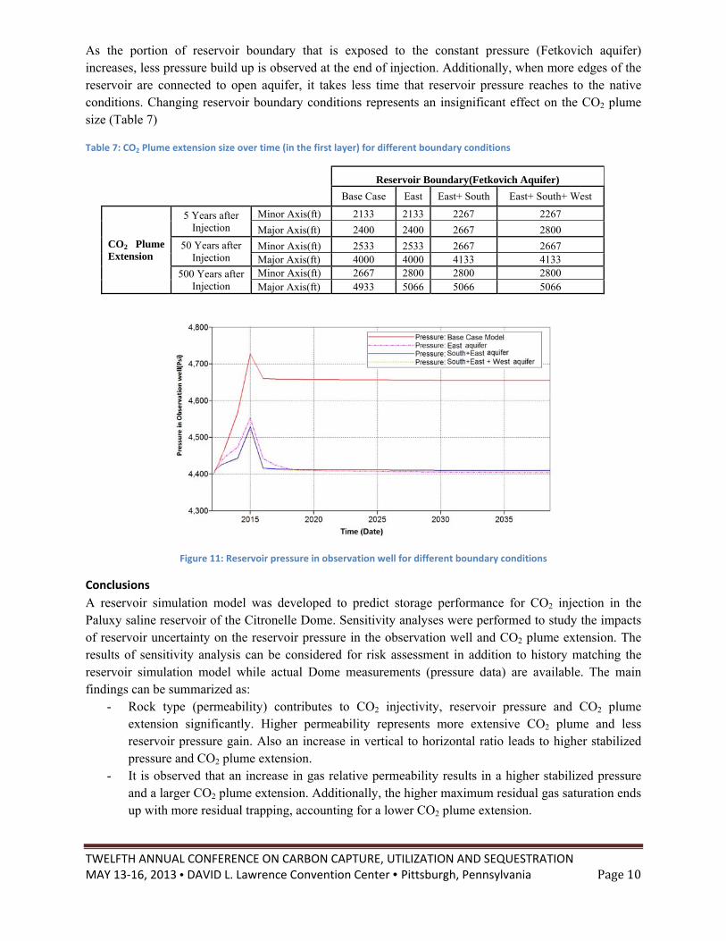
In this section, we assume that the saline reservoir in the Paluxy formation is not a closed system. A Fetkovich aquifer (which keeps the reservoir pressure constant at the reservoir boundaries) is assigned to the East, East- South and East-South-West edges of the reservoir (Figure 10). As shown in Figure11, reservoir pressure behavior in the open system is significantly different compared to what was observed in the previous sections. First of all, maximum reservoir pressure at the end of injection is much less (almost 200 psi) in the open systems. Secondly, the stabilized pressure reaches initial or native reservoir pressure after particular time.
Figure 10: Different locations for constant pressure boundary (Fetkovich aquifer)
TWELFTH ANNUAL CONFERENCE ON CARBON CAPTURE, UTILIZATION AND SEQUESTRATION MAY 13‐16, 2013 • DAVID L. Lawrence Convention Center • Pittsburgh, Pennsylvania Page10
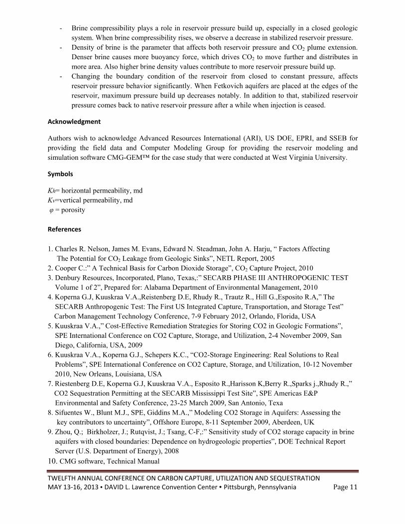
As the portion of reservoir boundary that is exposed to the constant pressure (Fetkovich aquifer) increases, less pressure build up is observed at the end of injection. Additionally, when more edges of the reservoir are connected to open aquifer, it takes less time that reservoir pressure reaches to the native conditions. Changing reservoir boundary conditions represents an insignificant effect on the CO2 plume size (Table 7)
Table 7: CO2 Plume extension size over time (in the first layer) for different boundary conditions
Reservoir Boundary(Fetkovich Aquifer)
Base Case East East+ South East+ South+ West
CO2 Plume Extension
5 Years after Injection
Minor Axis(ft) 2133 2133 2267 2267
Major Axis(ft) 2400 2400 2667 2800
50 Years after Injection
Minor Axis(ft) 2533 2533 2667 2667 Major Axis(ft) 4000 4000 4133 4133
500 Years after Injection
Minor Axis(ft) 2667 2800 2800 2800 Major Axis(ft) 4933 5066 5066 5066
Figure 11: Reservoir pressure in observation well for different boundary conditions
Conclusions
A reservoir simulation model was developed to predict storage performance for CO2 injection in the Paluxy saline reservoir of the Citronelle Dome. Sensitivity analyses were performed to study the impacts of reservoir uncertainty on the reservoir pressure in the observation well and CO2 plume extension. The results of sensitivity analysis can be considered for risk assessment in addition to history matching the reservoir simulation model while actual Dome measurements (pressure data) are available. The main findings can be summarized as:
- Rock type (permeability) contributes to CO2 injectivity, reservoir pressure and CO2 plume extension significantly. Higher permeability represents more extensive CO2 plume and less reservoir pressure gain. Also an increase in vertical to horizontal ratio leads to higher stabilized pressure and CO2 plume extension.
- It is observed that an increase in gas relative permeability results in a higher stabilized pressure and a larger CO2 plume extension. Additionally, the higher maximum residual gas saturation ends up with more residual trapping, accounting for a lower CO2 plume extension.
TWELFTH ANNUAL CONFERENCE ON CARBON CAPTURE, UTILIZATION AND SEQUESTRATION MAY 13‐16, 2013 • DAVID L. Lawrence Convention Center • Pittsburgh, Pennsylvania Page11
- Brine compressibility plays a role in reservoir pressure build up, especially in a closed geologic system. When brine compressibility rises, we observe a decrease in stabilized reservoir pressure.
- Density of brine is the parameter that affects both reservoir pressure and CO2 plume extension. Denser brine causes more buoyancy force, which drives CO2 to move further and distributes in more area. Also higher brine density values contribute to more reservoir pressure build up.
- Changing the boundary condition of the reservoir from closed to constant pressure, affects reservoir pressure behavior significantly. When Fetkovich aquifers are placed at the edges of the reservoir, maximum pressure build up decreases notably. In addition to that, stabilized reservoir pressure comes back to native reservoir pressure after a while when injection is ceased.
Acknowledgment
Authors wish to acknowledge Advanced Resources International (ARI), US DOE, EPRI, and SSEB for providing the field data and Computer Modeling Group for providing the reservoir modeling and simulation software CMG-GEM™ for the case study that were conducted at West Virginia University.
Symbols
Kh= horizontal permeability, md Kv=vertical permeability, md φ = porosity References
1. Charles R. Nelson, James M. Evans, Edward N. Steadman, John A. Harju, “ Factors Affecting The Potential for CO2 Leakage from Geologic Sinks”, NETL Report, 2005 2. Cooper C.:” A Technical Basis for Carbon Dioxide Storage”, CO2 Capture Project, 2010 3. Denbury Resources, Incorporated, Plano, Texas,:” SECARB PHASE III ANTHROPOGENIC TEST Volume 1 of 2”, Prepared for: Alabama Department of Environmental Management, 2010 4. Koperna G.J, Kuuskraa V.A.,Reistenberg D.E, Rhudy R., Trautz R., Hill G.,Esposito R.A,” The SECARB Anthropogenic Test: The First US Integrated Capture, Transportation, and Storage Test” Carbon Management Technology Conference, 7-9 February 2012, Orlando, Florida, USA 5. Kuuskraa V.A.,” Cost-Effective Remediation Strategies for Storing CO2 in Geologic Formations”, SPE International Conference on CO2 Capture, Storage, and Utilization, 2-4 November 2009, San Diego, California, USA, 2009 6. Kuuskraa V.A., Koperna G.J., Schepers K.C., “CO2-Storage Engineering: Real Solutions to Real Problems”, SPE International Conference on CO2 Capture, Storage, and Utilization, 10-12 November 2010, New Orleans, Louisiana, USA 7. Riestenberg D.E, Koperna G.J, Kuuskraa V.A., Esposito R.,Harisson K,Berry R.,Sparks j.,Rhudy R.,” CO2 Sequestration Permitting at the SECARB Mississippi Test Site”, SPE Americas E&P Environmental and Safety Conference, 23-25 March 2009, San Antonio, Texa 8. Sifuentes W., Blunt M.J., SPE, Giddins M.A.,” Modeling CO2 Storage in Aquifers: Assessing the key contributors to uncertainty”, Offshore Europe, 8-11 September 2009, Aberdeen, UK 9. Zhou, Q.; Birkholzer, J.; Rutqvist, J.; Tsang, C-F,:” Sensitivity study of CO2 storage capacity in brine aquifers with closed boundaries: Dependence on hydrogeologic properties”, DOE Technical Report Server (U.S. Department of Energy), 2008
10. CMG software, Technical Manual


