California Emissions Program:PM Reduction from EMD Switcher Locomotives
July 2006
by
Steven G. Fritz, P.E.Southwest Research Institute®
(210) [email protected]
and
Brian E. SmithTransportation Technology Center, Inc.
(719) [email protected]

CEP = California Emissions Program* Part of CARB diesel toxics reduction program* CARB looked for a voluntary PM reduction effort from the
railroad industry in lieu of greater use of CARB diesel fuel» Funded by BNSF & UP railroads
– $5M budget» Scope:
– PM reduction– Switchers– California
* CARB wants to see a Diesel Particulate Filter (DPF) installed and functioning on a switcher locomotive in California
1,500 hp EMD MP15 Switcher Locomotive

CEP Administration* R&D work for the Association of
American Railroads (AAR) is performed by the Transportation Technology Center, Inc (TTCI) in Pueblo, Colorado
* TTCI is the CEP program manager for BNSF & UP
* SwRI under contract with TTCI
* Regular updates to CARB
* AAR, CSX, and NS following project
* These issues will ultimately affect all railroads and the OEMs.
48-miles of test track

General Technical Approach* Phase 1 – Laboratory Screening (complete)
» Task 1: Install EMD 16-645E locomotive engine» Task 2: Reduce lubricating oil consumption
– Cylinder kits (pistons, rings, cylinder liners) (ASME ICES2003-549), CIMAC 2004
– Recirculated crankcase blowby (ASME ICEF2003-707)
– Valve stem seals– Rebuilt engine with low oil consumption parts
» Task 3: Screen candidate DPF and Oxidation Catalyst systems on test engine– Evaluated 13 different DOC and DPF systems– Selected top 3 for 500-hour initial durability test– Selected best performer for Phase 2 field implementation
* Phase 2 – Field Implementation of DPF on Switcher Locomotives
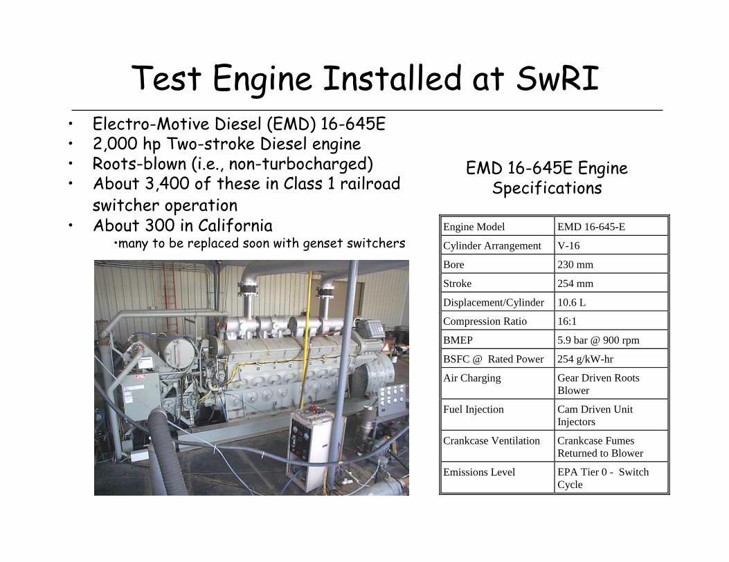
Test Engine Installed at SwRI
Engine Model EMD 16-645-E
Cylinder Arrangement V-16
Bore 230 mm
Stroke 254 mm
Displacement/Cylinder 10.6 L
Compression Ratio 16:1
BMEP 5.9 bar @ 900 rpm
BSFC @ Rated Power 254 g/kW-hr
Air Charging Gear Driven RootsBlower
Fuel Injection Cam Driven UnitInjectors
Crankcase Ventilation Crankcase FumesReturned to Blower
Emissions Level EPA Tier 0 - SwitchCycle
• Electro-Motive Diesel (EMD) 16-645E• 2,000 hp Two-stroke Diesel engine• Roots-blown (i.e., non-turbocharged)• About 3,400 of these in Class 1 railroad
switcher operation• About 300 in California
•many to be replaced soon with genset switchers
EMD 16-645E Engine Specifications

Question: What are the Baseline PM Emissionsfor EMD 645E Switcher Engines?
* It depends……there are several sources of available data.
1. 1995 AAR Report R885
» SwRI tested 5 EMD MP15AC locomotives (1,500 hp, 12-645E engines)
– 3 of the 5 were tested at all Notches and with PM measurements
» In-use testing for inventory and fuel injection timing effects
2. DOE/NREL Biodiesel Study
» EPA Certification Diesel & CARB diesel in an EMD GP38-2 (2,000 hp, 16-645E)
3. CEP Baseline Emissions – As Received
4. CEP – Current Configuration with low oil consumption parts and fresh injectors
Also;With what fuel?Over what test cycle?

Sources of “Baseline” EMD 645E PM Emission RatesEPA Switch Cycle
0.00
0.10
0.20
0.30
0.40
0.50
0.60
0.70
0.80
AAR R-885 NREL GP-38 EPA NREL GP-38 CARB CEP Baseline, EPA cert CEP, fresh injectors, Low-Oil Cons Parts, On-Hwy
Fuel
EPA
Sw
itch
Cyc
le P
M, g
/hp-
hr
EPA Tier 0 Switch duty-cycle maximum = 0.72 g/hp-hr
95% confidence interval of triplicate tests on each of three in-use locomotives =0.39 to 0.45 g/hp-hr

EMD 645E PM Composition
* Soluble Organic Fraction (SOF) relatively high;
» 77% over EPA Switch Duty Cycle
» SOF is high at all Notches
* 4-stroke engines characteristically have much lower SOF levels
* Aftertreatment system needs to be engineered to the exhaust PM characteristics
EMD 16-645-E Particulate AnalysisTriplicate FTP Baseline with Low Oil Consumption Components
0%
10%
20%
30%
40%
50%
60%
70%
80%
90%
100%
LowIdle
Idle DB-4 N1 N2 N3 N4 N5 N6 N7 N8
Notch
SOF,
per
cent
of T
otal
PM

Why is SOF so high? Lube Oil Consumption
* Oil consumption level of roots-blown EMD engines is relatively high» 3 to 10 times higher than
today’s truck engines* Affects aftertreatment
performance & durability:» Ash loading» Sulfur» “Souping” – liquid oil
accumulation in the exhaust manifolds during extended idling 0
0.5
1
1.5
2
2.5
3
On-
wy H
DD GE
EMD T
urbo
EMD R
oots
Fuel-S
pecific
Oil
Cons
, %

CEP Task 2: Reduced Oil Consumption Cylinder Kits
* Evaluated 7 cylinder kits or kit components to assess relative oil consumption
* Used SwRI-developed RTOC-III™
technique to measure oil consumption
3 candidate kits (4 each of C1, C2, and C3) evaluated simultaneously, in addition to the reference “R” kits
EMD power assembly showing piston, cylinder liner, and cylinder head

Reducing Oil Consumption

Oil Consumption & Sulfur
Fuel-Specific Oil Consumption (gal lube / gal fuel)2.0%1.5%1.0%0.5%0.1%% sulfur in lube
000000.00%5038251330.25%
10075502550.50%150113753880.75%20015010050101.00%25018812563131.25%30022515075151.50%
Fuel Sulfur Equivalent, ppm
Lube-oil derived sulfur will be an issue if a catalyzed trap is used, even with ultra-low sulfur diesel fuel.
On-Highway Truck Engine
Typical EMD 645E Engine

CEP Phase 1, Task 3: Aftertreatment Screening
* Challenges in Considering DOC or DPF for thisEMD 16-645E Application» Exhaust temperatures are very low» Compounded by switcher duty cycles
– 60% of the time at Idle– Idle shutdown system will likely be needed
» DPF Will likely require active regeneration– Electrical heating possible – lots of electrical power
available on the locomotive– Increased cost & complexity over passive systems– Additional fuel consumption penalty

0
100
200
300
400
500
600
700
Low Idle Idle DB4 N1 N2 N3 N4 N5 N6 N7 N8
Throttle Notch
Exha
ust T
emp.
, °C
Soot ignition temp. = 600 °C
JM CRT w/< 50 ppm S fuelCatalyzed Traps
Oxy Cat (HC, CO, 50% of SOF)
29.9% 29.9% 0.0% 12.4% 12.3% 5.8% 3.6% 3.6% 1.5% 0.2% 0.8%
EMD 16-645E Exhaust Temperatures2,000 hp @ 900 rpm
94% of operating time <250°C
Exhaust temperatures are too low for passive systems

Backpressure SensitivityAAR Corr. SFC Vs. Back Pressure
0.400
0.405
0.410
0.415
0.420
0.425
0.430
0.435
0.440
0.445
0.450
0.0 1.0 2.0 3.0 4.0 5.0 6.0 7.0 8.0 9.0
Back Pressure (in. Hg)
AA
R C
orr.
SFC
. ( L
b/H
p-H
r)
3.3%
EMD 16-645E at 2,000 hp rated power, Notch 8
As we add aftertreatment, and back pressure increases, there is a direct negative impact on fuel economy.
AA
R-co
rrec
ted
brak
e-sp
ecif
ic f
uel
cons
umpt
ion
(bsf
c), l
b/hp
-hr

Candidate DPF & Oxycat Evaluations
* Original plan was to screen “truck size” samples» 135 hp/cyl = 100 kW/cyl» 4 cylinders = 540 hp ≈ power of large truck engine
* Briefed MECA to invite supplier participation» MECA = Manufacturers of Emissions Controls Association
» Jan. 2002 and again in Nov. 2003» Very limited interest from MECA members
– Challenging application (cold exhaust, low duty cycle, high SOF)– Potential market size too small to justify R&D cost– Busy with near-term, higher volume projects
* Looked to large engine stationary source suppliers » Typical market is low-volume, custom-engineered applications.

Locomotive Space Limitations
* Need to be able to service engine without interference from exhaust manifolds or aftertreatment system
* Valve covers open for access to power assemblies

Screening Test Performance SummaryEPA Switch Cycle
0.00
0.10
0.20
0.30
0.40
0.50
0.60
0.70
0.80
AAR R-88
5NREL G
P-38 E
PANREL G
P-38 C
ARB
CEP Baseli
ne, E
PA cert
CEP, fres
h inje
ctors,
Low-O
il Con
s Part
s, On-H
wy Fue
l
Sys. A
: Flow
-Throug
h Cera
mic Mon
olith
Sys. B
: Elec
t. reg
en fil
ter
Sys. C
: Oxy
Cat (co
rrega
ted m
etal fo
il)
Sys. D
: Oxy
Cat => D
iesel
regen
SiC
soot
filter
- Rev
. 1
Sys. E
: Dies
el reg
en S
iC so
ot filt
er =>
Oxy
Cat - R
ev. 2
Sys. F
: Clos
e-Cou
pled O
xyca
t (leg
s + m
ain ch
ambe
r)
Sys. G
: Clos
e-Cou
pled O
xyca
t (leg
s only
) - R
ev. 2
Sys. H
: Oxy
cat+F
ilter+o
xyca
t (pas
sive)
Sys. I:
Dies
el reg
en SiC so
ot filt
er - R
ev. 3
Sys. J
: Clos
e-cou
pled o
xyca
t in ex
haus
t man
ifold
Sys. K
: Clos
e-cou
pled o
xyca
t in le
gs - R
ev. 3
Sys. L
: Clos
e-cou
pled o
xyca
t in le
gs - R
ev. 4
Sys. M
: Oxid
ation
Cata
lyst
PM E
mis
sion
s, g
/hp-
hr
N2 meltdown Too much
flow restriction
EPA Tier 0 maximum
Tier 1
Tier 2

Screening Test Performance SummaryEPA Line-Haul Cycle
0.00
0.10
0.20
0.30
0.40
0.50
0.60
0.70
0.80
AAR R-88
5NREL G
P-38 E
PA
NREL GP-38
CARB
CEP Bas
eline
, EPA ce
rt
CEP, fres
h inje
ctors,
Low-O
il Con
s Part
s, On-H
wy Fue
l
Sys. A
: Flow
-Thro
ugh C
eramic
Monoli
th
Sys. B
: Elec
t. reg
en fil
ter
Sys. C
: Oxy
Cat (co
rrega
ted m
etal fo
il)
Sys. D
: Oxy
Cat => D
iesel
regen
SiC so
ot filt
er - R
ev. 1
Sys. E
: Dies
el reg
en S
iC soot
filter
=> O
xyCat
- Rev
. 2
Sys. F
: Clos
e-Cou
pled O
xyca
t (leg
s + m
ain ch
ambe
r)
Sys. G
: Clos
e-Cou
pled O
xyca
t (leg
s only
) - Rev
. 2
Sys. H
: Oxy
cat+F
ilter+o
xyca
t (pas
sive)
Sys. I:
Dies
el reg
en S
iC so
ot filt
er - R
ev. 3
Sys. J
: Clos
e-cou
pled o
xyca
t in ex
haus
t man
ifold
Sys. K
: Clos
e-cou
pled o
xyca
t in le
gs - R
ev. 3
Sys. L
: Clos
e-cou
pled o
xyca
t in le
gs - R
ev. 4
Sys. M
: Oxid
ation
Cata
lyst
PM E
mis
sion
s, g
/hp-
hr
PM increase at high notches = sulfate formation
N2 meltdow
n
Restrictive at N8
PM increase at high notches =
sulfate formation
Too much flow
restriction
EPA Tier 0 maximum
Tier 1
Tier 2

CEP Phase 1: Summary/Conclusions
* Low oil consumption cylinder kits a logical first step in PM reductions» This is where most of the PM is coming from» Reduces the burden on the aftertreatment system
* Laboratory screening test of candidate aftertreatment systems was essential» Suppliers rarely “get it right” the first time» This is a challenging application» Screening on 2 or 4 cylinders of exhaust has allowed for screening several
candidate systems* If it works – will it fit?* Long term technology path not certain; DOC vs. DPF
– Capital cost– Installation cost– PM Emission reduction – initial and long term– Durability / Reliability / Maintenance – Operating cost (fuel consumption penalty)

What is Next ? CEP Phase 2* TTCI performed engine shock and
vibration characterization on revenue service switcher locomotives –completed
* Hug Engineering DPF selected for field implementation

Initial 2 Locomotives for DPF
BNSF3703 released from overhaul on 30-JUN-2006, BNSF working locomotive to SwRI now.
Equipped with Kim Hotstart DDHS (Diesel Driven Heating System) idle reduction system
UPY1378 overhauled in Fall 2006
Routed to SwRI in Feb. 2006 for Hug DPF mounting design concept meeting
Equipped with ZTR SmartStartIdle reduction system

CEP Phase 2 Program Schedule

DPF Installation & Test Plan

DPF Installation Considerations* Hug PDF units are heavy
(appx. 1150 lbs each)* Two filters required for
1,500 hp EMD 12-645E engine
* Will be mounted above main alternator and engine blowers
* Rail Sciences Inc. designing support frame structure» needs to withstand severe
shock and vibrations» 5 g longitudinal design

Summary
* First 2 locomotive DPF installations in North America will occur within the next 6 weeks
* Generate hard data on:» PM reduction efficiency» Cost effectiveness» Reliability / Maintenance Intervals
* If initial 2 installations are successful;» BNSF and UP have committed to 2 more locomotive
installations

Questions ?


