
PROJECT CHINA STONE
Mine Waste Storage Facility Conceptual Design Report C

November 2014
PROJECT CHINA STONE
MINE WASTE STORAGE FACILITY CONCEPTUAL DESIGN REPORT
REPO
RT
Report Number. 137635015-005-R-Rev0
Submitted to:Hansen Bailey Level 15, 215 Adelaide St Brisbane, QLD On behalf of MacMines Austasia
Appendix C | Mine Waste Storage Facility Conceptual Design Report
PROJECT CHINA STONE EIS - REJECTS MANAGEMENT
November 2014 Report No. 137635015-005-R-Rev0 i
Table of Contents
1.0 INTRODUCTION ........................................................................................................................................................ 1
2.0 SCOPE OF WORK .................................................................................................................................................... 1
3.0 DESIGN BASIS ......................................................................................................................................................... 2
3.1 Design drivers and criteria ............................................................................................................................ 2
3.2 Input parameters........................................................................................................................................... 2
4.0 MATERIAL CHARACTERISATION .......................................................................................................................... 3
4.1 Overview ....................................................................................................................................................... 3
4.2 Foundation .................................................................................................................................................... 3
4.2.1 Geology ................................................................................................................................................... 3
4.2.2 Field investigation ................................................................................................................................... 4
4.2.3 Laboratory testing ................................................................................................................................... 4
4.2.4 Surface conditions .................................................................................................................................. 4
4.2.5 Subsurface conditions ............................................................................................................................. 4
4.2.6 Engineering assessment ......................................................................................................................... 4
5.0 DESIGN ANALYSES ................................................................................................................................................. 5
5.1 Geotechnical stability .................................................................................................................................... 5
5.2 Consequence Category Assessment ............................................................................................................ 6
6.0 TSF AND PSWSF DESIGN ....................................................................................................................................... 8
6.1 Site preparation ............................................................................................................................................ 8
6.1.1 Topsoil and cover material ...................................................................................................................... 8
6.1.2 Foundation preparation ........................................................................................................................... 8
6.1.3 Seepage collection system ..................................................................................................................... 8
6.2 TSF ............................................................................................................................................................... 8
6.2.1 TSF Staging ............................................................................................................................................ 8
6.2.2 Tailings delivery system .......................................................................................................................... 9
6.2.3 Tailings deposition strategy ..................................................................................................................... 9
6.2.4 Decant pond management ...................................................................................................................... 9
6.2.5 Spillway ................................................................................................................................................. 10
6.2.6 Surface drainage ................................................................................................................................... 10
6.2.7 Monitoring ............................................................................................................................................. 10
Appendix C | Mine Waste Storage Facility Conceptual Design Report

PROJECT CHINA STONE EIS - REJECTS MANAGEMENT
November 2014 Report No. 137635015-005-R-Rev0 ii
6.3 PSWSF ....................................................................................................................................................... 10
6.3.1 PSWSF staging..................................................................................................................................... 10
6.3.2 Power station waste placement ............................................................................................................ 11
6.3.3 Surface drainage ................................................................................................................................... 11
6.3.4 Monitoring ............................................................................................................................................. 11
7.0 REHABILITATION AND CLOSURE ........................................................................................................................ 12
7.1 Closure and final landform .......................................................................................................................... 12
7.2 Revegetation .............................................................................................................................................. 12
7.3 Runoff management ................................................................................................................................... 12
8.0 LIMITATIONS .......................................................................................................................................................... 12
TABLES Table 1: Total cumulative volume of tailings and power station waste ................................................................................ 2
Table 2: Material Parameters .............................................................................................................................................. 6
Table 3: Summary of Stability Analyses Results ................................................................................................................. 6
Table 4: TSF staged layout plan ......................................................................................................................................... 9
Table 5: PSWSF staged layout plan ................................................................................................................................. 11
Table 6: Laboratory test summary ..................................................................................................................................... 16
PLATES Plate 1: Annual and cumulative tailings and power station waste volumes. ........................................................................ 3
Plate 2: Design storm storage requirements. ...................................................................................................................... 7
FIGURES
Figure 1: Project Location
Figure 2: Project Layout
Figure 3: TSF and PSWSF Arrangement
Figure 4: Site Investigation
Figure 5: Design Details
Figure 6: Staging Plan Sheet 1 of 2
Figure 7: Staging Plan Sheet 2 of 2
APPENDICES APPENDIX A Test Pit and Borehole Reports
APPENDIX B Laboratory Test Results
Appendix C | Mine Waste Storage Facility Conceptual Design Report

PROJECT CHINA STONE EIS - REJECTS MANAGEMENT
November 2014 Report No. 137635015-005-R-Rev0 iii
APPENDIX C Results of Slope Stability Analysis
APPENDIX D Limitations
Appendix C | Mine Waste Storage Facility Conceptual Design Report
PROJECT CHINA STONE EIS - REJECTS MANAGEMENT
November 2014 Report No. 137635015-005-R-Rev0 1
1.0 INTRODUCTION Golder Associates Pty Ltd (Golder) was commissioned by Hansen Bailey on behalf of MacMines Austasia Pty Ltd (the proponent) to complete a conceptual design report for mine waste storage facilities as part of the Environmental Impact Statement (EIS) for Project China Stone (the project).
The project involves the construction and operation of a large-scale coal mine on a greenfield site in Central Queensland. The project site (the area that will ultimately form the mining leases for the project) is remote, being located approximately 270 km south of Townsville and 300 km west of Mackay at the northern end of the Galilee Basin (Figure 1). The closest townships are Charters Towers, approximately 285 km by road to the north, and Clermont, approximately 260 km by road to the south-east. The project site comprises approximately 20,000 ha of well vegetated land, with low-lying scrub in the south and east and a densely vegetated ridgeline, known as ‘Darkies Range’, running north to south through the western portion of the site.
The mine will produce up to approximately 55 million tonnes per annum (Mtpa) of Run of Mine (ROM) thermal coal. Coal will be mined using both open cut and underground mining methods (Figure 2). Open cut mining operations will involve multiple draglines and truck and shovel pre-stripping. Underground mining will involve up to three operating longwalls. Coal will be washed and processed on site and product coal will be transported from site by rail. It is anticipated that mine construction will commence in 2016 and the mine life will be in the order of 50 years.
The majority of the mine infrastructure will be located in the eastern portion of the project site (Figure 2). Infrastructure will include coal handling and preparation plants (CHPPs), stockpiles, conveyors, rail loop and train loading facilities, workshops, dams, tailings storage facility (TSF) and a power station. A workforce accommodation village and private airstrip will also be located in the eastern part of the project site.
2.0 SCOPE OF WORK The project includes a conventional wet tailings storage facility (TSF) for life-of-mine out-of-pit tailings storage and a power station waste storage facility (PSWSF) with capacity to store dry coal ash generated in the first ten years of operations by the on-site power station. The layout of the TSF and PSWSF are shown in Figure 3.
Coarse reject generated from the Coal Handling and Preparation Plant (CHPP) over the life of the mine and dry coal ash from the power station, after the first ten years of operations, will be stored within the open cut mine overburden emplacement and are not discussed further in this report.
The scope of work undertaken by Golder for this conceptual design report included:
Calculation of the volume of life-of-mine tailings and power station waste produced in the first ten years of operations.
Sizing of the TSF and PSWSF and associated ultimate footprint areas.
Preparation of staged development plans and operating methods for the TSF and PSWSF.
Geotechnical field investigations of the TSF and PSWSF foundation area.
Design analyses of the TSF and PSWSF.
A number of other technical studies that address elements of tailings and power station waste storage have been undertaken as part of the EIS. These include an assessment of the geochemical properties of the tailings and power station waste materials, a groundwater assessment and a mine water management study. These studies are reported in separate specialist reports that form appendices to the EIS and the EIS main volume provides an overview of all the environmental issues that are relevant to tailings and power station waste storage. For this reason, this conceptual design report does not address the geochemistry of the waste materials, potential seepage from the TSF, or management of surface water (other than providing a high level overview).
Appendix C | Mine Waste Storage Facility Conceptual Design Report

PROJECT CHINA STONE EIS - REJECTS MANAGEMENT
November 2014 Report No. 137635015-005-R-Rev0 2
3.0 DESIGN BASIS 3.1 Design drivers and criteria The design parameters for the TSF and PSWSF are as follows:
Minimum static Factor of Safety (FoS) of 1.3 at the end of construction.
Minimum FoS of 1.5 under long term steady state conditions.
Assuming an average dry density of 1.0 t/m3 the total tailings volume corresponds to approximately 96 Mm3.
Downstream slopes for the TSF and PSWSF of 1V:6H at closure.
Upstream slopes for the TSF of 1V:2H.
Downstream slopes for the TSF (other than the north-eastern embankment) and temporary slopes for the PSWSF of 1V:4H during operations.
Maximum embankments height of 34 m and 30 m for the TSF and PSWSF, respectively. The PSWSF crest elevation is lower than the adjacent TSF, commensurate with the lower elevation of the natural ground surface at the PSWSF.
An assumed beach slope of 1V:500H for the deposited tailings in the TSF.
Inclusion of a seepage collection system around the perimeter of both the TSF and PSWSF.
3.2 Input parameters Table 1 summarises the life-of-mine volume of tailings and the volume of power station waste generated in the first ten years of operations. Plate 1 illustrates the annual and cumulative tailings and power station waste volumes to be stored in the TSF and PSWSF. The volume of tailings and power station waste has been calculated using a final average dry density of 1 t/m3.
Table 1: Total cumulative volume of tailings and power station waste
Tailings (Mm3) Power Station Waste (Mm3)
96.1 16.4
Appendix C | Mine Waste Storage Facility Conceptual Design Report

PROJECT CHINA STONE EIS - REJECTS MANAGEMENT
November 2014 Report No. 137635015-005-R-Rev0 3
Plate 1: Annual and cumulative tailings and power station waste volumes.
4.0 MATERIAL CHARACTERISATION 4.1 Overview Design of the TSF and PSWSF requires characterisation of the foundation soils at the site in order to assess the geotechnical stability of the facilities. A field investigation program to assess the geotechnical characteristics of the foundation soils has been undertaken as part of this assessment.
Geotechnical testing and characterisation of the tailings and power station waste has not been undertaken at this stage due to lack of availability of representative samples. The current assessment has been based on Golder’s experience with similar facilities. Further analyses based on representative samples of the waste materials will be conducted during the detailed design phase.
The testing and characterisation of foundation soils are provided in the following sections.
4.2 Foundation 4.2.1 Geology Two bores (MB 20 and MB 32) were drilled by others in this area to investigate the nature of the underlying strata (Figure 4).
The foundation area of the TSF/PSWF site is characterised by highly weathered Tertiary sediments of claystone and fine to medium grained, weakly indurated sandstone. Highly localised Quaternary sediments of fluvial origin are associated with present drainage features. A thin cover of sandy soils covers the surface.
The Tertiary sediments are underlain by the Joe Joe Group. The Joe Joe Group comprises conglomerate, lithic sandstone, siltstone, minor mudstone and coal. The Joe Joe Group is the base unit of the Galilee Basin. The younger sediments of the Clematis Sandstone, Rewan Formation and the Betts Creek Beds all outcrop west of the TSF/PSWSF site.
Appendix C | Mine Waste Storage Facility Conceptual Design Report

PROJECT CHINA STONE EIS - REJECTS MANAGEMENT
November 2014 Report No. 137635015-005-R-Rev0 4
4.2.2 Field investigation Fieldwork was carried out between the 6th and 13th of February 2014 and included:
The investigation of 35 sites (Figure 4) within the proposed TSF/PSWSF footprint by:
Excavation of 23 test pits.
Drilling of 12 boreholes.
The performance of dynamic cone penetrometer tests adjacent to test pits and boreholes.
Inspections of visible drainage lines within the footprint.
The test pits were excavated using a backhoe and a 450 mm standard bucket. The auger holes were drilled using a Landcruiser mounted drill rig and a 90 mm diameter auger.
The excavation of the testing locations was supervised by an engineering geologist from Golder and the locations were discontinued at a maximum depth of 3.5 m, with prior refusal being encountered in the majority of the locations. Strata identification was based on inspection of the excavated materials. Geotechnical samples of selected subsurface materials were recovered for laboratory testing, as described in the following sections. Test pit and boreholes reports are provided in Appendix A.
4.2.3 Laboratory testing Laboratory testing was carried out on representative disturbed and undisturbed samples to assess soil classification (particle size distribution, moisture content and plasticity), Emerson Class, compaction and permeability.
A summary of the laboratory test results along with the detailed report sheets are included in Appendix B.
4.2.4 Surface conditions The TSF/PSWSF footprint is located in the south-eastern section of the project site (Figure 2).
At the time of the investigation, the site was being used for cattle grazing. The footprint area is traversed by two drainage lines that drain to the east to an upper tributary of Tomahawk Creek (Figure 4). These drainage lines were dry at the time of the field investigation.
The site was mostly grassed and densely populated with medium mature to mature, native trees. There had been only small amounts of rainfall at the site leading up to the time of the investigation and the bare ground surface was mostly dry and hardset, whilst the vegetated ground surface was dry to moist. The hardness of the subgrade materials is expected to vary with seasonal conditions, with both the surface and subsurface soils being susceptible to softening during wet weather periods.
4.2.5 Subsurface conditions The investigation revealed that the site is typically underlain by a silty or clayey sand soil of medium density. The sandy soil became cemented near surface and the cemented material increased in density until refusal was reached at most sites within 3.5 m.
Site geology and investigation by others, confirms that highly weathered claystone and fine to medium grained, weakly indurated sandstone underlies the soil strata and that there is no shallow groundwater in the area. Groundwater was encountered at only one of the geotechnical investigation sites, undertaken adjacent to a drainage line.
4.2.6 Engineering assessment The findings of the field investigation are typically consistent with the expected geological conditions at the site and indicate a relatively shallow soil cover over the weathered lateritic sedimentary soil profiles. The key engineering features of the foundation conditions, as they relate to the TSF and PSWSF, are summarised as follows:
Appendix C | Mine Waste Storage Facility Conceptual Design Report

PROJECT CHINA STONE EIS - REJECTS MANAGEMENT
November 2014 Report No. 137635015-005-R-Rev0 5
Soil Strength – Other than the surface soils, which will be removed or reworked as part of the site preparation, the soils are typically at least dense or very stiff and this increases with depth as the strata becomes more cemented. For the conceptual design, soil strength parameters have been selected for two layers to represent the uncemented and cemented soils. A layer thickness of 1 m has been selected for the uncemented zone and is deemed to reflect the ground conditions as identified in the field investigation.
Rock Strength – It is expected that highly weathered claystone and fine to medium grained, weakly indurated sandstone underlies the site at depth; however the investigation did not penetrate the dense cemented clayey sands that are likely to represent the weathered zone of the underlying lithified materials. For the design, the rock has not been included in the modelling and this is considered a conservative assumption.
Soil Permeability – The near surface soils vary from clays to clayey sands which will lead to some natural variability in permeability. Testing of two undisturbed samples from 1.2 m depth gave coefficient of permeability values of 1.6 x 10⁻¹⁰ m/s and 9.3 x 10⁻¹⁰ m/s, which is consistent with literature values for clays (for example Bowles1 provides a range of 10-9 to 10-11 m/s). The permeability of clayey sands is expected to be greater, though still relatively low as the clay content typically exceeds 20%.
Dispersivity – Testing indicates that the soil at the site does not disperse when immersed in distilled water, even when remoulded and therefore standard erosion control measures are likely to be effective.
Construction Materials – Soils that are mixtures of sand and clay are typically good construction materials as they can be readily handled and in the right proportions, can be compacted to achieve relatively low permeability and high strength fills. The clays are typically of medium plasticity which reduces the likelihood of shrinkage cracking. The clay has a low permeability when compacted (around 1.9 x 10⁻¹⁰ m/s from testing) making it suitable for embankment construction and preparation of a low permeability foundation layer.
5.0 DESIGN ANALYSES 5.1 Geotechnical stability Slope stability analyses were undertaken for the TSF and PSWSF with the intent of estimating the FoS of the proposed closure and temporary slopes under a variety of load conditions. The closure slope will be at 1V:6H while the temporary slopes have been designed as 1V:4H, as shown on Figure 5.
The minimum FoS required to meet the design basis and standard engineering practice for each case are:
FoS > 1.5 for long-term (closure) conditions.
FoS > 1.3 for short-term conditions (i.e. immediately after placement or after a rainfall event).
The analyses undertaken for both the closure and temporary slopes included:
Case 1. Tailings placed with no clay liner and elevated water table – long-term conditions.
Case 2. Tailings placed with clay liner and elevated water table – long-term conditions
Case 3. Tailings with clay liner and elevated water table – short-term conditions.
Case 4. Tailings with no clay liner and elevated water table – short-term conditions.
Case 5. PSWSF
The material parameters used during the analysis are based on the findings of the site specific investigations and laboratory testing and Golder experience. The material parameters are shown in Table 2.
1 Bowles, J.E., Foundation Analysis and Design, Mc Graw-Hill, USA, 1996
Appendix C | Mine Waste Storage Facility Conceptual Design Report

PROJECT CHINA STONE EIS - REJECTS MANAGEMENT
November 2014 Report No. 137635015-005-R-Rev0 6
Table 2: Material Parameters
Materials Unit Weight (kN/m3)
Effective Stress Total Stress
Cohesion (kPa) Friction Angle (degrees)
Undrained Shear Strength (kPa)
Power station waste 18 0 33 -
Tailings 16 0 28 -
Foundation 18 2 30 -
Very Dense Sand 20 10 34 -
Clay Liner 18 10 26 150
The analysis was undertaken using Slope/W 2012 which uses limit equilibrium methods to solve for FoS, and the Morgenstern-Price method was adopted. The Slope/W analyses indicate that both the closure and temporary slopes exceed the minimum FoS requirements, as summarised in Table 3.
Table 3: Summary of Stability Analyses Results Case Estimated FoS Target FoS
1 3.39 1.5
2 3.39 1.5
3 2.50 1.3
4 2.51 1.3
5 3.75 1.5
The results of the analyses are provided in Appendix C.
Analysis of the permanent slopes indicates that the factors of safety exceed target values and are expected to be stable in the long term. The temporary slopes also have factors of safety against instability that exceed the target value, suggesting that 1V:4H is a suitable maximum steepness for these slopes.
5.2 Consequence Category Assessment A preliminary consequence category assessment of the conceptual TSF has been undertaken in accordance with DEHP (2014)2.
The findings are summarised as follows:
Dams are located such that loss of life is not expected as a result of TSF failure.
No surface water or drinking water supplies are known within the project surroundings or downstream catchment. TSF failure is therefore unlikely to contaminate water supplies used for human consumption.
No significant or sensitive environmental features or important public facilities/utilities are present in the likely TSF failure path.
The cost for rehabilitation of land in the TSF failure path and compensation is expected to cost between $1 million and $10 million.
2 Manual for Assessing Consequence Categories and Hydraulic Performance of Structures, EM635 Version 4, April 2014, Queensland Government Department of Environment and Heritage Protection.
Appendix C | Mine Waste Storage Facility Conceptual Design Report

PROJECT CHINA STONE EIS - REJECTS MANAGEMENT
November 2014 Report No. 137635015-005-R-Rev0 7
The water management system has been configured to ensure tailings and mine-affected water are contained. The preliminary assessment concludes that the proposed TSF is considered a ‘significant’ consequence category structure and will be considered a ‘regulated structure’ under the Environmental Protection Act 1994 (EP Act). A further detailed consequence category assessment including a full dam break analysis will be conducted at the detailed design stage to confirm the consequence category and regulated status under the EP Act.
Hydraulic design criteria including the Design Storage Allowance (DSA), Extreme Storm Storage (ESS) and Mandatory Reporting Level (MRL) have been determined for the TSF in accordance with the Manual requirements for significant consequence category dams. This approach is considered to be appropriate and conservative for the current conceptual design phase. The TSF consequence category will be revaluated during the detailed design phase considering the three failure event scenarios;
1) Failure to contain - seepage.
2) Failure to contain – overtopping.
3) Dam break.
The ESS, MRL and DSA requirements for regulated storages are shown in Plate 2.
Plate 2: Design storm storage requirements.
In accordance with DEHP (2014)2 the definitions for the DSA, ESS and MRL are:
The ESS is a storm storage allowance determined based on the 72 hour duration 1:10 AEP storm event for a significant consequence category dam. The ESS is equivalent to 202 mm of rainfall.
The MRL is a level at which the dam has a remaining available volume equivalent to the ESS allowance and this must be marked in a clearly visible location.
The DSA is an available volume provided in a dam as at 1 November each year in order to prevent a discharge from that dam up to a specified annual exceedance probability (AEP) wet season event. For a significant consequence category dam a 1:20 AEP wet season is appropriate and this corresponds to 690 mm of rainfall.
An allowance has been made in the TSF design for storage of the DSA rainfall. The detailed design of the TSF will include engineered spillways and the staged construction of the TSF will accommodate the ESS below the spillway level.
ESS Volume
Mandatory Reporting Level (MRL)
Des ign Storage Allowance (DSA)FreeboardSpi llway Invert
Embankment Crest Operating Decant Pond Level
Ta ilings
Embankment
Appendix C | Mine Waste Storage Facility Conceptual Design Report

PROJECT CHINA STONE EIS - REJECTS MANAGEMENT
November 2014 Report No. 137635015-005-R-Rev0 8
6.0 TSF AND PSWSF DESIGN 6.1 Site preparation 6.1.1 Topsoil and cover material At the commencement of construction of the PSWSF and each stage of the TSF, the footprint area will be cleared and grubbed. Grubbing will be followed by the removal and stockpiling of available soil resources from the TSF/PSWSF foundation areas, including materials suitable for reuse as topsoil and/or capping material. The EIS Soils and Land Suitability Report provides further information on available topsoil and capping material resources.
The existing topsoil resource (i.e. the best quality growth medium) is approximately 1.3 m thick across the TSF/PSWSF footprint. Material intended for reuse in TSF/PSWSF rehabilitation as a plant growth medium (i.e. topsoil and selected subsoil) will be removed and stockpiled in a manner that will aim to preserve the overall structure of these materials. The EIS Rehabilitation Section describes the way in which this material will be managed.
6.1.2 Foundation preparation After the topsoil and cover material, and any embankment material, have been removed from the TSF/PSWSF footprint, the foundation will be inspected and suitable preparation measures taken to provide a low permeability foundation. It is anticipated that this will involve:
Ripping the upper soil layers.
Moisture conditioning (i.e. watering) of the clay liner materials to achieve close to optimum moisture condition so that a low permeability layer is formed during compaction.
Compaction of the clay liner using a pad-foot or sheeps-foot roller of sufficient weight to achieve compaction of at least 95% of standard dry density.
Should the inspection show that insufficient clay soils are present to achieve design requirements an alternative design solution would be developed and this may include imported clay materials or an engineered liner solution.
6.1.3 Seepage collection system A perimeter seepage collection system will be installed along the downstream toe of the TSF embankment and along the downstream toe of the external PSWSF slopes to collect and transport any water seeping from the TSF and PSWSF. Typical cross-sections of the seepage collection drains are shown on Figure 5. The location of the perimeter seepage collection system is shown in Figures 6 and 7.
The seepage drain would be lined with geofabric material and will include slotted pipes surrounded by gravel.
The seepage collection system will drain to a series of collection sumps. Seepage water from the collection sumps will be pumped to the TSF.
6.2 TSF 6.2.1 TSF Staging A conceptual TSF operating plan has been developed for EIS purposes. A comprehensive operational plan will be developed during detailed design and maintained over the life of the facility.
The conceptual TSF operating plan is described in the remainder of this section and shown on Figures 6 and 7. The operating plan demonstrates that the TSF can be developed to accommodate life-of-mine tailings ina manner that ensures that tailings are properly contained.
Appendix C | Mine Waste Storage Facility Conceptual Design Report

PROJECT CHINA STONE EIS - REJECTS MANAGEMENT
November 2014 Report No. 137635015-005-R-Rev0 9
The progressive development of the TSF is illustrated at seven stages over the life of the mine, including closure, in Figures 6 and 7. The TSF embankments will be raised in stages using the downstream construction method.
Table 4 presents the tailings volumes to be stored at the selected years of mine operation, including closure, as well as both the TSF embankment elevation and maximum embankment height required.
Table 4: TSF staged layout plan
Stage Project Year Cumulative Tailings (m3)
Embankment Elevation (RL m)
Max Embankment Height (m)
1 5 9,353,341 315.9 12.42 10 30,124,955 322.8 19.33 15 51,683,638 327.7 24.24 20 68,690,125 331.5 28.05 30 93,537,121 336.8 33.36 49 96,112,024 337.5 34.07 Closure 96,112,024 337.5 34.0
The required maximum footprint area for the TSF corresponds to 603 ha for the closure stage and requires a maximum embankment height of approximately 34 m.
6.2.2 Tailings delivery system Tailings would be delivered from the CHPP to the TSF as a slurry via a pipeline system. The pipeline system would be distributed around the inner crest of the TSF embankment walls and full pipe spigot off-takes would be set at approximately 100 m centres. Flow into the off-takes would be controlled by valves and the flow would discharge into a slotted pipe laid down the inner slope of the TSF embankments to the base of the facility.
6.2.3 Tailings deposition strategy The tailings deposition strategy will involve sequencing of the active tailings discharge spigots in order to progressively develop a beach around the perimeter embankment towards the centre of the TSF. This method will maintain a tailings decant water pond in the centre of the active TSF area. Tailings water will collect in the decant pond following deposition of solids from the tailings slurry on the beach areas. Rainfall runoff from within the active TSF area will also collect in the decant pond.
For each TSF development stage the spigot off-take system would be set around the inner crest of the TSF embankments to ensure the tailings beach can be maintained, ensuring the efficient placement of tailings solids within the TSF and maintenance of the central decant pond.
This deposition strategy will also allow for the progressive drying and consolidation of successive layers of deposited tailings which will increase the shear strength of the final tailings beach. This deposition strategy is well-established and commonly used in conventional wet tailings storage facilities in the coal mine mining industry.
6.2.4 Decant pond management A pontoon mounted return water pump will be moored in the TSF decant pond. The pump will operate automatically to maintain a low water level within the decant pond. The pump will transfer water from the decant pond to the Return Water Dam. The Return Water Dam will be a priority water supply for the CHPP.
Appendix C | Mine Waste Storage Facility Conceptual Design Report

PROJECT CHINA STONE EIS - REJECTS MANAGEMENT
November 2014 Report No. 137635015-005-R-Rev0 10
6.2.5 Spillway The TSF will include temporary spillway structures during the TSF staging. The north embankment of the TSF has been selected as the location of the temporary spillway structures. The initial temporary spillway will be required once the TSF embankment perimeter is enclosed in Year 15. The temporary spillways will be constructed as part of the staged TSF embankment raising. The spillways will be sized to handle the 1:100 AEP flow event in accordance with DEHP (2014) requirements for a significant consequence category dam.
6.2.6 Surface drainage Water management for the project, including the TSF, is addressed in greater detail in the EIS Surface Water Section. The broad principles for surface drainage management for the TSF area are described below.
Prior to the construction of the TSF embankment around the full perimeter of the TSF, diversion drains will be constructed at the northern end of the TSF to isolate the active TSF catchment (Figure 6).
Once the full embankment is constructed around the perimeter of the TSF it will isolate the TSF catchment (Figure 6).
Runoff from the external slopes of the TSF embankment will be collected in toe drains and directed to sediment traps for control of suspended sediment prior to draining from site. Drainage from established rehabilitation on the external TSF embankment slopes will be allowed to drain from site.
6.2.7 Monitoring A monitoring program will be designed to monitor key environmental and design performance indicators. It will include:
Regular inspections and annual survey of the deposited tailings beach and decant pond.
Regular inspection of the spigot off-takes system, tailings deposition and operation of the decant pumping system.
Regular inspection of the surface drainage around the perimeter of the TSF and the seepage collection system.
Annual inspection of the TSF embankment and spillways.
Surface water monitoring including TSF decant pond water quality and return water volumes pumped to the Return Water Dam (refer to EIS Surface Water section for details).
Monitoring of pore water pressures in the TSF embankment.
Monitoring of groundwater levels and water quality in the vicinity of the TSF (refer EIS Groundwater Report).
The results of the monitoring will be used to assess the performance of the TSF and to undertake regular reviews of the design and operating plans.
6.3 PSWSF 6.3.1 PSWSF staging A conceptual PSWSF operating plan has been developed for EIS purposes. A detailed operational plan will be developed and maintained over the life of the facility.
The conceptual PSWSF is described in the remainder of this section and shown on Figures 6 and 7. Based on the assigned footprint area and embankment slopes for the PSWSF, the operating plan has been developed to accommodate the amount of power station waste estimated to be generated over the first ten years of operations. Table 5 includes the volumes to be stored during mine operation and closure for the PSWSF.
Appendix C | Mine Waste Storage Facility Conceptual Design Report

PROJECT CHINA STONE EIS - REJECTS MANAGEMENT
November 2014 Report No. 137635015-005-R-Rev0 11
Table 5: PSWSF staged layout plan
Project Year Cumulative Power station waste (m3)
Embankment Elevation (RL m)
Embankment Height (m)
5 2,737,800 307 9.5
10 16,426,800 320 30.5
Closure 16,426,800 320 30.5
The assigned footprint area for the PSWSF for closure corresponds to 80 ha and requires a maximum embankment height of approximately 30 m. The PSWSF has a storage capacity of approximately 16.4 Mm3.The remaining power station waste will be stored within the open cut mine overburden emplacement.
6.3.2 Power station waste placement The dry power station waste will be placed using trucks in a similar fashion to development of an out-of-pit overburden emplacement. Each truck will be loaded at the power station and transported to the designated fill area of the PSWSF. Initially, the material will be paddock dumped across the site at a specified lift height. Subsequent lifts will continue to be placed, with the extent of each lift designated to form the ultimate 1V:6H external slopes.
6.3.3 Surface drainage Water management for the project, including the PSWSF, is addressed in greater detail in the EIS Surface Water Section. The broad principles for surface drainage management for the PSWSF area are described below.
Diversion drains will be constructed around the perimeter of the PSWSF to isolate the active PSWSF catchment (Figure 6).
The active emplacement areas will be developed so that surface runoff drains to internal collection sumps. Runoff that collects in these internal sumps will be pumped to the TSF.
Runoff from the external slopes of the PSWSF embankment will be collected in toe drains and directed to sediment traps for control of suspended sediment prior to draining from site. Drainage from established rehabilitation on the external PSWSF embankment slopes will be allowed to drain from site.
6.3.4 Monitoring A monitoring program will be designed to monitor key environmental and design performance indicators. It will include:
Regular and annual surveys of the emplaced power station waste including assessment of storage capacity and monument survey to assess settlement of the facility with annual engineering survey reports.
Regular inspection of the surface drainage around the perimeter of the PSWSF and the seepage collection system.
Regular inspection of the internal drainage collection system and monitoring of internal surface runoff quality.
Monitoring of pore water pressures in the PSWSF.
Monitoring of groundwater quality in the vicinity of the PSWSF (refer EIS Groundwater Report).
The results of the monitoring will be used to assess the performance of the PSWSF and to undertake regular reviews of the design and operating plans.
Appendix C | Mine Waste Storage Facility Conceptual Design Report

PROJECT CHINA STONE EIS - REJECTS MANAGEMENT
November 2014 Report No. 137635015-005-R-Rev0 12
7.0 REHABILITATION AND CLOSURE 7.1 Closure and final landform At closure any remaining decant water will be pumped out of the TSF decant pond and mine overburden or coarse rejects will be used to fill the TSF to the embankment crest level. The final surface will be profiled with a 2% grade to promote runoff and minimise ponding of water on the final surface of the TSF. Mine overburden will also be placed on any external 1V:4H embankment slopes of the TSF to provide final slopes of 1V:6H.
The external slopes of the PSWSF will be shaped to provide an overall slope of 1V:6H at closure. This will be achieved by dozing any temporary benches and inter-bench slopes. The top surface of the PSWSF will be profiled with a 2% grade to promote runoff.
Both facilities will have maximum final rehabilitation slopes of 1V:6H with maximum slope heights of 34 m. Based on successful rehabilitation experience at other mine sites these slopes and maximum slope heights should result in a stable landform.
7.2 Revegetation The geochemical characterisation of the tailings and power station coal ash is discussed in detail in the EIS Geochemistry Report. The report concluded that these waste materials have relatively benign geochemistry and no special management measures are required for their handling and permanent storage.
In order to ensure the successful revegetation of the TSF and PSWSF, the final surface of stored waste material in each facility will be covered with a total of 1.3 m of topsoil and growth medium. This level of soil cover will provide sufficient rooting depth and enable successful revegetation and a stable final landform.
The EIS Soils and Land Suitability Report describes the availability of topsoil and cover material.
7.3 Runoff management The TSF and PSWSF will be shaped at closure to promote runoff and runoff control structures will be installed to manage design flows. Runoff will be controlled using contour drains constructed at regular spacing on the slopes. The contour drains will be constructed with a gradient of approximately 1% and will be topsoiled and seeded with grass.
8.0 LIMITATIONS Your attention is drawn to the document - “Limitations”, which is included in Appendix D of this report. The statements presented in this document are intended to advise you of what your realistic expectations of this report should be, and to present you with recommendations on how to minimise the risks associated with the services provided for this project. The document is not intended to reduce the level of responsibility accepted by Golder Associates, but rather to ensure that all parties who may rely on this report are aware of the responsibilities each assumes in so doing.
Appendix C | Mine Waste Storage Facility Conceptual Design Report

PROJECT CHINA STONE EIS - REJECTS MANAGEMENT
November 2014 Report No. 137635015-005-R-Rev0
Report Signature Page
GOLDER ASSOCIATES PTY LTD
Amanda Barrett Associate, Principal Geotechnical Engineer
AB/PJC
A.B.N. 64 006 107 857
Golder, Golder Associates and the GA globe design are trademarks of Golder Associates Corporation.
\\golder.gds\gap\brisbane\jobs\des\2013\137635015 - china stone eis rejects design\deliverables\137635015-005-r-rev0 tsf design report.docx
Appendix C | Mine Waste Storage Facility Conceptual Design Report

PACIFICOCEAN
Hay Point
Abbot Point
Galilee
Basin
Bowen
Basin
MACKAY
BOWEN
ROCKHAMPTONEMERALD BLACKWATER
CHARTERS TOWERS
TOWNSVILLE
Sarina
BaralabaSpringsure
Biloela
Collinsville
Middlemount
Alpha
Clermont
Ayr
Ingham
Belyando Crossing
Pentland
CoppabellaMoranbah
Dysart
Nebo
Project China Stone Site
Legend
Coal BasinRailway
Road
Export Port
Horizontal Scale
0 80 km
N
SYDNEYCANBERRA
HOBART
MELBOURNE
ADELAIDE
PERTH
DARWIN
Mackay
Gladstone
BRISBANE
Townsville
FIGURE 1
P R O J E C T C H I N A S T O N E
Project Location
7 59
0 00
0 N
420 000 E410 000 E
7 60
0 00
0 N
Tailings StorageFacility
Accommodation
Power Station WasteStorage Facility
Village
Airstrip
O p e n C u t M i n i n g A r e a
U n d e r g r o u n dM i n i n g A r e a
U n d e r g r o u n dM i n i n g A r e a
S o u t h e r n
N o r t h e r n
Power Station
NorthernUnderground MIA
SouthernUnderground MIA
Coal Handling &Preparation Plants
Rail Loop
Train Loadout
Raw CoalStockpilesOpen Cut MIA
Product CoalStockpiles
Project SiteLegend
Project Layout
FIGURE 2
N
Mine Infrastructure AreaOpen Cut Mining Area
0 3km
Horizontal Scale
DATUM: GDA 94Zone : 55
HB 1152 STONE EIS - Project Layout (SR) (21/10/2014)
Underground Mining Area
Appendix C | Mine Waste Storage Facility Conceptual Design Report

RAW COALSTOCKPILES
MIA
OPEN CUTMIA
OPEN CUTMINE EXTENTS
HAUL ROAD
ACCESS ROAD
POWERSTATION
PRODUCT COALSTOCKPILE
7 590 000 N 7 590 000 N
420
000
E42
0 00
0 E
7 587 500 N 7 587 500 N
417
500
E41
7 50
0 E
415
000
E41
5 00
0 E
422
500
E42
2 50
0 E
CH 0m
CH 500m
CH 100
0m
CH 1
500m
CH 2
000m
CH 2
500m
CH
300
0mCH
350
0m
CH 4000m
CH 4500m
CH 5000
m
CH 5500
m
CH 6000m
CH 6500m
CH 7000m
CH 7500m
CH 8000m
CH 8500m
CH 9000m
CH 9500mCH 9641m
COAL HANDLING ANDPREPARATION PLANTS
SOUTHERNUNDERGROUND MIA
TAILINGS STORAGEFACILITY
POWER STATION WASTESTORAGE FACILITY
POWER STATIONTRAIN LOADOUT
RAIL LOOP
CONSULTANT
DESIGN
PREPARED
REVIEW
APPROVED
YYYY-MM-DD TITLE
PROJECT No. Rev.
PROJECTCLIENT
Pat
h: \\
gold
er.g
ds\G
AP
\Bris
bane
\CA
D\D
es\2
013\
1376
3501
5 - C
hina
Sto
ne E
IS R
ejec
ts D
esig
n\FI
GU
RE
S\
| F
ile N
ame:
137
6350
15-0
05-M
-F00
2.dw
g
025
mm
IF T
HIS
ME
AS
UR
EM
EN
T D
OE
S N
OT
MA
TCH
WH
AT
IS S
HO
WN
, TH
E S
HE
ET
SIZ
E H
AS
BE
EN
MO
DIF
IED
FR
OM
: IS
O A
3
137635015CONTROL005-R
FIGURE
F0030
2014-10-31
ERN
CM
AB
AB
PROJECT CHINA STONE••••
MACMINES••••
TSF AND POWER STATION WASTE STORAGE FACILITYARRANGEMENT
••
0
1:25,000
500 1,000
METRES
NOT FOR CONSTRUCTION••
A
B
C
LEGENDPOWER STATION WASTE HAUL ROAD
Appendix C
| Mine W
aste Storage Facility Conceptual D
esign Report

7 592 000 N 7 592 000 N
420
000
E42
0 00
0 E
7 590 000 N 7 590 000 N
418
000
E41
8 00
0 E
416
000
E41
6 00
0 E
422
000
E
TP01
TP02
TP03
TP04
TP05
TP06
TP07
TP08
TP09
TP10
TP11
TP12
TP13
TP14
TP15
TP16
TP17
TP18
TP19
TP20
TP21
TP22TP23
TP24
TP25
TP26
TP27
TP28
TP29
TP30
TP31
TP32
TP33
TP34
TP35
PROPOSED POWERSTATION WASTE
STORAGE FACILITY
PROPOSED TAILINGSSTORAGE FACILITY
TP17
CONSULTANT
DESIGN
PREPARED
REVIEW
APPROVED
YYYY-MM-DD TITLE
PROJECT No. Rev.
PROJECTCLIENT
Pat
h: \\
gold
er.g
ds\G
AP
\Bris
bane
\CA
D\D
es\2
013\
1376
3501
5 - C
hina
Sto
ne E
IS R
ejec
ts D
esig
n\FI
GU
RE
S\
| F
ile N
ame:
137
6350
15-0
05-M
-F00
3.dw
g
025
mm
IF T
HIS
ME
AS
UR
EM
EN
T D
OE
S N
OT
MA
TCH
WH
AT
IS S
HO
WN
, TH
E S
HE
ET
SIZ
E H
AS
BE
EN
MO
DIF
IED
FR
OM
: IS
O A
3
137635015CONTROL005-R
FIGURE
F0040
2014-10-31
ERN
CM
AB
AB
LEGEND
COMPLETED TEST PIT LOCATION
ULTIMATE TSF/PSWSF FOOTPRINT
PROJECT CHINA STONE••••
MACMINES••••
SITE INVESTIGATION
••
NOT FOR CONSTRUCTION••
1:20,000
1,0000
METRES
500
Appendix C
| Mine W
aste Storage Facility Conceptual D
esign Report

Appendix C
| Mine W
aste Storage Facility Conceptual D
esign Report

Appendix C
| Mine W
aste Storage Facility Conceptual D
esign Report

Appendix C
| Mine W
aste Storage Facility Conceptual D
esign Report

PROJECT CHINA STONE EIS - REJECTS MANAGEMENT
November 2014 Report No. 137635015-005-R-Rev0
APPENDIX A Test Pit and Borehole Reports
Appendix C | Mine Waste Storage Facility Conceptual Design Report

L
H
L-M
M
H
R
Silty SANDfine to medium grained, pale brown to grey, with some roots
Clayey SANDfine to medium grained, pale grey and orange brown, traceroots
trace fine to medium grained gravel
with some fine to medium, sub-rounded to rounded gravel,moderately cemented bandnot cemented
weakly cemented
moderately cemented
END OF BOREHOLE @ 1.90 mREFUSALGROUNDWATER NOT ENCOUNTERED
SM
SC0.30
0.50
0.90
1.00
1.30
1.70
AD
T
DS 0.50-0.80 m
DS 1.30-1.50 m
Gro
undw
ater
not
enc
ount
ered
D -M
D -M
D
D -M
L
D
VD
SHEET: 1 OF 1
Field Material DescriptionSamplingDrilling
PE
NE
TRA
TIO
NR
ES
ISTA
NC
E
SOIL/ROCK MATERIAL DESCRIPTION
US
CS
SY
MB
OL
RE
CO
VE
RE
D
WA
TER
RLDEPTH
DE
PTH
(met
res)
ME
THO
D
GR
AP
HIC
LOG
SAMPLE ORFIELD TEST
DRILL RIG: Landcruiser Drill RigCONTRACTOR: Cardno
LOGGED: SECHECKED: AB
GAP gINT FN. F01bRL3
CLIENT:PROJECT:LOCATION:
JOB NO:
DATE: 13/2/14DATE: 6/11/14
This report of borehole must be read in conjunction with accompanying notes and abbreviations. It has been prepared forgeotechnical purposes only, without attempt to assess possible contamination. Any references to potential contamination are for
information only and do not necessarily indicate the presence or absence of soil or groundwater contamination.
REPORT OF BOREHOLE: TP001
Hansen BaileyTSF InvestigationChina Stone Project
137635015
COORDS: 416961.0 m E 7592266.0 m N MGA94 56
SURFACE RL: DATUM: AHDINCLINATION: -90°HOLE DEPTH: 1.90 m
GA
P 8
_08.
04 L
IB.G
LB L
og G
AP
NO
N-C
OR
ED
FU
LL P
AG
E G
INT.
GP
J <
<Dra
win
gFile
>> 1
0/11
/201
4 11
:55
8.3
0.00
4 D
atge
l Too
ls
MO
ISTU
RE
CO
ND
ITIO
NC
ON
SIS
TEN
CY
DE
NS
ITY
DCP TEST (AS1289.6.3.2)Blows per 100 mm
5 10 15 200 25
20/50 HB
0.0
0.5
1.0
1.5
2.0
2.5
3.0
3.5
4.0
4.5
5.0
Appendix C | Mine Waste Storage Facility Conceptual Design Report

L
M
M-H
H
SILTlow liquid limit, brown to dark brown, with some fine grainedsand, with some roots
Clayey SANDfine grained, pale brown and pale orange, trace mediumgrained sand, weakly cemented, trace roots
trace black, medium, sub-angular to sub-rounded gravel
with pockets of moderately cemented material
with no roots
trace medium to coarse, rounded gravel
TEST PIT DISCONTINUED @ 2.80 mREFUSALGROUNDWATER NOT ENCOUNTERED
ML
SC0.30
0.70
1.00
1.60
2.20
BH
DS 0.30-0.60 m
BDS 1.30-2.00 m
DS 2.60-2.80 m
Gro
undw
ater
not
enc
ount
ered
D
D -M
F
D
VD
27
SHEET: 1 OF 1
Field Material DescriptionSamplingExcavation
EX
CA
VATI
ON
RE
SIS
TAN
CE
SOIL/ROCK MATERIAL DESCRIPTION
US
CS
SY
MB
OL
RE
CO
VE
RE
D
WA
TER
RLDEPTH
DE
PTH
(met
res)
ME
THO
D
GR
AP
HIC
LOG
SAMPLE ORFIELD TEST
MACHINE: Cat 432ECONTRACTOR:
LOGGED: SECHECKED: AB
GAP gINT FN. F01fRL3
CLIENT:PROJECT:LOCATION:
JOB NO:
DATE: 6/2/14DATE: 6/11/14
This report of test pit must be read in conjunction with accompanying notes and abbreviations. It has been prepared forgeotechnical purposes only, without attempt to assess possible contamination. Any references to potential contamination are for
information only and do not necessarily indicate the presence or absence of soil or groundwater contamination.
REPORT OF TEST PIT: TP002
Hansen BaileyTSF InvestigationChina Stone Project
137635015
COORDS: 416408.0 m E 7591959.0 m N MGA94 56SURFACE RL: DATUM: AHD
PIT DEPTH: 2.80 mBUCKET TYPE: 450mm Standard
GA
P 8
_08.
04 L
IB.G
LB L
og G
AP
NO
N-C
OR
ED
FU
LL P
AG
E G
INT.
GP
J <
<Dra
win
gFile
>> 1
0/11
/201
4 11
:55
8.3
0.00
4 D
atge
l Too
ls
MO
ISTU
RE
CO
ND
ITIO
NC
ON
SIS
TEN
CY
DE
NS
ITY
DCP TEST (AS1289.6.3.2)Blows per 100 mm
5 10 15 200 25
0.0
0.5
1.0
1.5
2.0
2.5
3.0
3.5
4.0
4.5
5.0
Appendix C | Mine Waste Storage Facility Conceptual Design Report

L
M
M-H
H
Sandy SILTlow liquid limit, brown, fine grained sand, with some roots
pale brown, trace roots
Clayey SANDfine grained, pale brown, weakly cemented, with trace roots
becoming orange brown, trace roots, trace moderatelycemented lenses
weakly cemented
TEST PIT DISCONTINUED @ 3.00 mTARGET DEPTHGROUNDWATER NOT ENCOUNTERED
ML
SC
0.30
0.60
1.70
2.60
BH
DS 0.30-0.60 m
DS 1.00-1.20 m
DS 1.70-2.00 m
Gro
undw
ater
not
enc
ount
ered
D -M
D
D -M
F
D
VD
D
SHEET: 1 OF 1
Field Material DescriptionSamplingExcavation
EX
CA
VATI
ON
RE
SIS
TAN
CE
SOIL/ROCK MATERIAL DESCRIPTION
US
CS
SY
MB
OL
RE
CO
VE
RE
D
WA
TER
RLDEPTH
DE
PTH
(met
res)
ME
THO
D
GR
AP
HIC
LOG
SAMPLE ORFIELD TEST
MACHINE: Cat 432ECONTRACTOR:
LOGGED: SECHECKED: AB
GAP gINT FN. F01fRL3
CLIENT:PROJECT:LOCATION:
JOB NO:
DATE: 6/2/14DATE: 6/11/14
This report of test pit must be read in conjunction with accompanying notes and abbreviations. It has been prepared forgeotechnical purposes only, without attempt to assess possible contamination. Any references to potential contamination are for
information only and do not necessarily indicate the presence or absence of soil or groundwater contamination.
REPORT OF TEST PIT: TP003
Hansen BaileyTSF InvestigationChina Stone Project
137635015
COORDS: 417708.0 m E 7592074.0 m N MGA94 56SURFACE RL: DATUM: AHD
PIT DEPTH: 3.00 mBUCKET TYPE: 450mm Standard
GA
P 8
_08.
04 L
IB.G
LB L
og G
AP
NO
N-C
OR
ED
FU
LL P
AG
E G
INT.
GP
J <
<Dra
win
gFile
>> 1
0/11
/201
4 11
:55
8.3
0.00
4 D
atge
l Too
ls
MO
ISTU
RE
CO
ND
ITIO
NC
ON
SIS
TEN
CY
DE
NS
ITY
DCP TEST (AS1289.6.3.2)Blows per 100 mm
5 10 15 200 25
0.0
0.5
1.0
1.5
2.0
2.5
3.0
3.5
4.0
4.5
5.0
Appendix C | Mine Waste Storage Facility Conceptual Design Report

L
M-H
R
Silty SANDfine grained, brown, low liquid limit, trace clay, with someroots
Sandy CLAYmedium plasticity, orange and pale grey
Sandy GRAVELfine to coarse grained, red/orange and yellow/brown, withsome sub-rounded to rounded cobbles
Sandy CLAYmedium plasticity, red/grey and red/yellow
SANDSTONEfine grained, red/purple and pale grey, very low to lowstrength, extremely weatheredTEST PIT DISCONTINUED @ 1.75 mREFUSALGROUNDWATER NOT ENCOUNTEREDPossible perched aquifer at 0.75-1.0 m after rainfall, moist towet during investigation
SM
CI
GP
CI
0.40
0.75
1.00
1.70
BH
BDS 1.00-1.20 m
U50 1.20-1.30 m
1.30 mPP = 500 kPa
Gro
undw
ater
not
enc
ount
ered
M
M -W
M
MD
St -VSt
VD
SHEET: 1 OF 1
Field Material DescriptionSamplingExcavation
EX
CA
VATI
ON
RE
SIS
TAN
CE
SOIL/ROCK MATERIAL DESCRIPTION
US
CS
SY
MB
OL
RE
CO
VE
RE
D
WA
TER
RLDEPTH
DE
PTH
(met
res)
ME
THO
D
GR
AP
HIC
LOG
SAMPLE ORFIELD TEST
MACHINE: Cat 432ECONTRACTOR:
LOGGED: SECHECKED: AB
GAP gINT FN. F01fRL3
CLIENT:PROJECT:LOCATION:
JOB NO:
DATE: 6/2/14DATE: 6/11/14
This report of test pit must be read in conjunction with accompanying notes and abbreviations. It has been prepared forgeotechnical purposes only, without attempt to assess possible contamination. Any references to potential contamination are for
information only and do not necessarily indicate the presence or absence of soil or groundwater contamination.
REPORT OF TEST PIT: TP004
Hansen BaileyTSF InvestigationChina Stone Project
137635015
COORDS: 416776.0 m E 7591461.0 m N MGA94 56SURFACE RL: DATUM: AHD
PIT DEPTH: 1.75 mBUCKET TYPE: 450mm Standard
GA
P 8
_08.
04 L
IB.G
LB L
og G
AP
NO
N-C
OR
ED
FU
LL P
AG
E G
INT.
GP
J <
<Dra
win
gFile
>> 1
0/11
/201
4 11
:55
8.3
0.00
4 D
atge
l Too
ls
MO
ISTU
RE
CO
ND
ITIO
NC
ON
SIS
TEN
CY
DE
NS
ITY
DCP TEST (AS1289.6.3.2)Blows per 100 mm
5 10 15 200 25
HB
0.0
0.5
1.0
1.5
2.0
2.5
3.0
3.5
4.0
4.5
5.0
Appendix C | Mine Waste Storage Facility Conceptual Design Report

L
H
R
Silty CLAYmedium plasticity, pale brown to grey, with some roots
Sandy CLAYmedium plasticity, orange/brown and grey, fine grained sand,trace roots
SANDSTONEfine, granular, pale grey to grey brown, well cemented, withsome macro-pores
TEST PIT DISCONTINUED @ 1.30 mREFUSALGROUNDWATER NOT ENCOUNTERED
CI
CI0.30
1.10
BH
BDS 0.30-1.00 m
U50 0.40-0.75 m
U50 0.80-1.05 m
DS 1.10-1.30 m
Gro
undw
ater
not
enc
ount
ered
M
F
VSt
H
SHEET: 1 OF 1
Field Material DescriptionSamplingExcavation
EX
CA
VATI
ON
RE
SIS
TAN
CE
SOIL/ROCK MATERIAL DESCRIPTION
US
CS
SY
MB
OL
RE
CO
VE
RE
D
WA
TER
RLDEPTH
DE
PTH
(met
res)
ME
THO
D
GR
AP
HIC
LOG
SAMPLE ORFIELD TEST
MACHINE: Cat 432ECONTRACTOR:
LOGGED: SECHECKED: AB
GAP gINT FN. F01fRL3
CLIENT:PROJECT:LOCATION:
JOB NO:
DATE: 6/2/14DATE: 6/11/14
This report of test pit must be read in conjunction with accompanying notes and abbreviations. It has been prepared forgeotechnical purposes only, without attempt to assess possible contamination. Any references to potential contamination are for
information only and do not necessarily indicate the presence or absence of soil or groundwater contamination.
REPORT OF TEST PIT: TP005
Hansen BaileyTSF InvestigationChina Stone Project
137635015
COORDS: 417094.0 m E 7591132.0 m N MGA94 56SURFACE RL: DATUM: AHD
PIT DEPTH: 1.30 mBUCKET TYPE: 450mm Standard
GA
P 8
_08.
04 L
IB.G
LB L
og G
AP
NO
N-C
OR
ED
FU
LL P
AG
E G
INT.
GP
J <
<Dra
win
gFile
>> 1
0/11
/201
4 11
:55
8.3
0.00
4 D
atge
l Too
ls
MO
ISTU
RE
CO
ND
ITIO
NC
ON
SIS
TEN
CY
DE
NS
ITY
DCP TEST (AS1289.6.3.2)Blows per 100 mm
5 10 15 200 25
HB
0.0
0.5
1.0
1.5
2.0
2.5
3.0
3.5
4.0
4.5
5.0
Appendix C | Mine Waste Storage Facility Conceptual Design Report
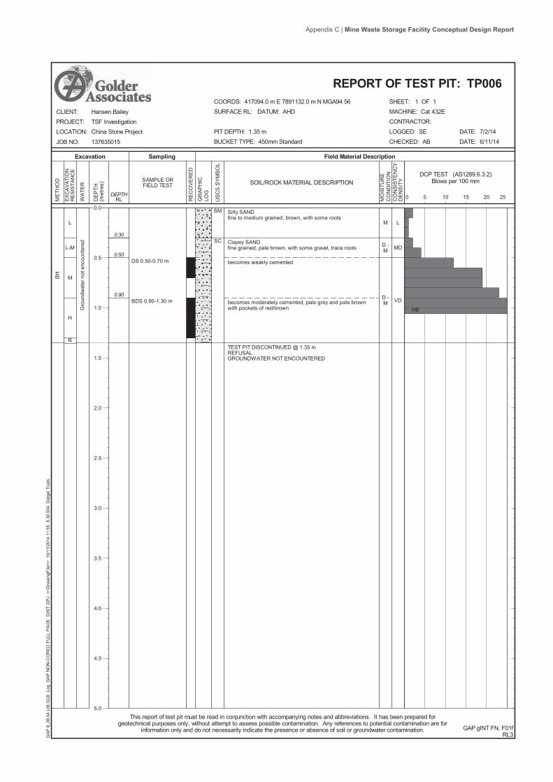
L
L-M
M
H
R
Silty SANDfine to medium grained, brown, with some roots
Clayey SANDfine grained, pale brown, with some gravel, trace roots
becomes weakly cemented
becomes moderately cemented, pale grey and pale brownwith pockets of red/brown
TEST PIT DISCONTINUED @ 1.35 mREFUSALGROUNDWATER NOT ENCOUNTERED
SM
SC0.30
0.50
0.90
BH
DS 0.50-0.70 m
BDS 0.90-1.30 m
Gro
undw
ater
not
enc
ount
ered
M
D -M
D -M
L
MD
VD
SHEET: 1 OF 1
Field Material DescriptionSamplingExcavation
EX
CA
VATI
ON
RE
SIS
TAN
CE
SOIL/ROCK MATERIAL DESCRIPTION
US
CS
SY
MB
OL
RE
CO
VE
RE
D
WA
TER
RLDEPTH
DE
PTH
(met
res)
ME
THO
D
GR
AP
HIC
LOG
SAMPLE ORFIELD TEST
MACHINE: Cat 432ECONTRACTOR:
LOGGED: SECHECKED: AB
GAP gINT FN. F01fRL3
CLIENT:PROJECT:LOCATION:
JOB NO:
DATE: 7/2/14DATE: 6/11/14
This report of test pit must be read in conjunction with accompanying notes and abbreviations. It has been prepared forgeotechnical purposes only, without attempt to assess possible contamination. Any references to potential contamination are for
information only and do not necessarily indicate the presence or absence of soil or groundwater contamination.
REPORT OF TEST PIT: TP006
Hansen BaileyTSF InvestigationChina Stone Project
137635015
COORDS: 417094.0 m E 7891132.0 m N MGA94 56SURFACE RL: DATUM: AHD
PIT DEPTH: 1.35 mBUCKET TYPE: 450mm Standard
GA
P 8
_08.
04 L
IB.G
LB L
og G
AP
NO
N-C
OR
ED
FU
LL P
AG
E G
INT.
GP
J <
<Dra
win
gFile
>> 1
0/11
/201
4 11
:55
8.3
0.00
4 D
atge
l Too
ls
MO
ISTU
RE
CO
ND
ITIO
NC
ON
SIS
TEN
CY
DE
NS
ITY
DCP TEST (AS1289.6.3.2)Blows per 100 mm
5 10 15 200 25
HB
0.0
0.5
1.0
1.5
2.0
2.5
3.0
3.5
4.0
4.5
5.0
Appendix C | Mine Waste Storage Facility Conceptual Design Report

L
M
M-H
H
R
SILTlow liquid limit, pale brown to grey, with some fine grainedsand, trace roots
Sandy CLAYlow plasticity, pale brown, fine grained sand, with some fine tomedium, sub-rounded to rounded gravel
weakly cemented
moderately cemented
with some gravelly lenses
medium plasticity, well cemented
END OF BOREHOLE @ 2.40 mREFUSALGROUNDWATER NOT ENCOUNTERED
ML
CL
CI
0.30
1.00
1.30
1.80
2.00
AD
T
DS 0.40-0.70 m
DS 1.30-1.80 m
DS 2.20-2.40 m
Gro
undw
ater
not
enc
ount
ered
D
D
Topsoil
SHEET: 1 OF 1
Field Material DescriptionSamplingDrilling
PE
NE
TRA
TIO
NR
ES
ISTA
NC
E
SOIL/ROCK MATERIAL DESCRIPTION
US
CS
SY
MB
OL
RE
CO
VE
RE
D
WA
TER
RLDEPTH
DE
PTH
(met
res)
ME
THO
D
GR
AP
HIC
LOG
SAMPLE ORFIELD TEST
DRILL RIG: Landcruiser Drill RigCONTRACTOR: Cardno
LOGGED: SECHECKED: AB
GAP gINT FN. F01aRL3
CLIENT:PROJECT:LOCATION:
JOB NO:
DATE: 11/2/14DATE: 6/11/14
This report of borehole must be read in conjunction with accompanying notes and abbreviations. It has been prepared forgeotechnical purposes only, without attempt to assess possible contamination. Any references to potential contamination are for
information only and do not necessarily indicate the presence or absence of soil or groundwater contamination.
REPORT OF BOREHOLE: TP007
Hansen BaileyTSF InvestigationChina Stone Project
137635015
COORDS: 418103.0 m E 7591580.0 m N MGA94 56
SURFACE RL: DATUM: AHDINCLINATION: -90°HOLE DEPTH: 2.40 m
GA
P 8
_08.
04 L
IB.G
LB L
og G
AP
NO
N-C
OR
ED
FU
LL P
AG
E G
INT.
GP
J <
<Dra
win
gFile
>> 1
0/11
/201
4 11
:55
8.3
0.00
4 D
atge
l Too
ls
MO
ISTU
RE
CO
ND
ITIO
NC
ON
SIS
TEN
CY
DE
NS
ITY
STRUCTURE ANDADDITIONAL
OBSERVATIONS
0.0
0.5
1.0
1.5
2.0
2.5
3.0
3.5
4.0
4.5
5.0
Appendix C | Mine Waste Storage Facility Conceptual Design Report

L
M-H
L-M
M-H
H
R
Silty SANDfine grained, brown, with some roots
Clayey SANDfine grained, medium to high plasticity, pale brown/orange
with some fine to medium, sub-rounded gravel
GRAVELfine to coarse, grey and pale grey, sub-rounded to rounded
Sandy CLAYmedium plasticity, grey and orange, with some fine tomedium, sub-rounded to rounded gravel, fine grained sand
Clayey SANDfine grained, pale grey and pale brown, with pockets of red /black, moderately cemented
Sandy CLAYmedium to high plasticity, pale grey and grey/white, withsome fine to medium, sub-rounded gravel, fine grained sand,trace gravelly bandsTEST PIT DISCONTINUED @ 2.20 mREFUSALGROUNDWATER ENCOUNTERED @ 0.90 m DEPTH
SM
SC
GP
CI
SC
CI
0.25
0.70
0.90
1.20
1.70
2.00
BH
DS 0.30-0.50 m
DS 0.90-1.20 m
BDS 1.30-1.70 m
DS 2.00-2.20 m
08/0
2/14
M
M -W
W
D -M
D
L
VL
L
D -VD
SHEET: 1 OF 1
Field Material DescriptionSamplingExcavation
EX
CA
VATI
ON
RE
SIS
TAN
CE
SOIL/ROCK MATERIAL DESCRIPTION
US
CS
SY
MB
OL
RE
CO
VE
RE
D
WA
TER
RLDEPTH
DE
PTH
(met
res)
ME
THO
D
GR
AP
HIC
LOG
SAMPLE ORFIELD TEST
MACHINE: Cat 432ECONTRACTOR:
LOGGED: SECHECKED: AB
GAP gINT FN. F01fRL3
CLIENT:PROJECT:LOCATION:
JOB NO:
DATE: 8/2/14DATE: 6/11/14
This report of test pit must be read in conjunction with accompanying notes and abbreviations. It has been prepared forgeotechnical purposes only, without attempt to assess possible contamination. Any references to potential contamination are for
information only and do not necessarily indicate the presence or absence of soil or groundwater contamination.
REPORT OF TEST PIT: TP008
Hansen BaileyTSF InvestigationChina Stone Project
137635015
COORDS: 417513.0 m E 7590674.0 m N MGA94 56SURFACE RL: DATUM: AHD
PIT DEPTH: 2.20 mBUCKET TYPE: 450mm Standard
GA
P 8
_08.
04 L
IB.G
LB L
og G
AP
NO
N-C
OR
ED
FU
LL P
AG
E G
INT.
GP
J <
<Dra
win
gFile
>> 1
0/11
/201
4 11
:55
8.3
0.00
4 D
atge
l Too
ls
MO
ISTU
RE
CO
ND
ITIO
NC
ON
SIS
TEN
CY
DE
NS
ITY
DCP TEST (AS1289.6.3.2)Blows per 100 mm
5 10 15 200 25
HB
0.0
0.5
1.0
1.5
2.0
2.5
3.0
3.5
4.0
4.5
5.0
Appendix C | Mine Waste Storage Facility Conceptual Design Report

L
L-M
M
M-H
R
Sandy SILTlow liquid limit, pale brown, fine with some roots
SILTlow liquid limit, pale brown, with some fine grained sand,trace roots
Clayey SANDfine grained, pale brown, medium plasticity clay
trace fine to medium, sub-rounded to rounded gravel, andweakly cemented
Sandy CLAYlow plasticity, pale brown, fine grained sand, trace fine tomedium sub-rounded gravel, trace of sandy lenses,moderately cemented
END OF BOREHOLE @ 1.70 mREFUSALGROUNDWATER NOT ENCOUNTERED
ML
ML
SC
CL
0.30
0.50
0.80
1.30
AD
T
DS 0.50-0.80 m
BDS 1.30-1.70 m
Gro
undw
ater
not
enc
ount
ered
D
VSt
F
MD
VD
H
SHEET: 1 OF 1
Field Material DescriptionSamplingDrilling
PE
NE
TRA
TIO
NR
ES
ISTA
NC
E
SOIL/ROCK MATERIAL DESCRIPTION
US
CS
SY
MB
OL
RE
CO
VE
RE
D
WA
TER
RLDEPTH
DE
PTH
(met
res)
ME
THO
D
GR
AP
HIC
LOG
SAMPLE ORFIELD TEST
DRILL RIG: Landcruiser Drill RigCONTRACTOR: Cardno
LOGGED: SECHECKED: AB
GAP gINT FN. F01bRL3
CLIENT:PROJECT:LOCATION:
JOB NO:
DATE: 11/2/14DATE: 6/11/14
This report of borehole must be read in conjunction with accompanying notes and abbreviations. It has been prepared forgeotechnical purposes only, without attempt to assess possible contamination. Any references to potential contamination are for
information only and do not necessarily indicate the presence or absence of soil or groundwater contamination.
REPORT OF BOREHOLE: TP009
Hansen BaileyTSF InvestigationChina Stone Project
137635015
COORDS: 418869.0 m E 7591559.0 m N MGA94 56
SURFACE RL: DATUM: AHDINCLINATION: -90°HOLE DEPTH: 1.70 m
GA
P 8
_08.
04 L
IB.G
LB L
og G
AP
NO
N-C
OR
ED
FU
LL P
AG
E G
INT.
GP
J <
<Dra
win
gFile
>> 1
0/11
/201
4 11
:55
8.3
0.00
4 D
atge
l Too
ls
MO
ISTU
RE
CO
ND
ITIO
NC
ON
SIS
TEN
CY
DE
NS
ITY
DCP TEST (AS1289.6.3.2)Blows per 100 mm
5 10 15 200 25
0.0
0.5
1.0
1.5
2.0
2.5
3.0
3.5
4.0
4.5
5.0
Appendix C | Mine Waste Storage Facility Conceptual Design Report

L
M
M-H
H
R
Silty SANDfine grained, brown to dark brown, with some roots
Silty SANDfine grained, pale brown, with some medium plasticity clay,trace roots
Silty SANDfine grained, pale grey and grey with pockets of red /yellow/black, moderately cemented, trace fine to medium,sub-rounded to rounded red gravel
becomes gravelly, fine to coarse, sub-rounded, grey and grey /red
TEST PIT DISCONTINUED @ 1.50 mREFUSALGROUNDWATER NOT ENCOUNTERED
SM
SM / SC
SM
0.30
1.00
1.30
BH
DS 0.30-0.70 m
DS 1.30-1.50 m
Gro
undw
ater
not
enc
ount
ered
D
L
L -MD
VD
SHEET: 1 OF 1
Field Material DescriptionSamplingExcavation
EX
CA
VATI
ON
RE
SIS
TAN
CE
SOIL/ROCK MATERIAL DESCRIPTION
US
CS
SY
MB
OL
RE
CO
VE
RE
D
WA
TER
RLDEPTH
DE
PTH
(met
res)
ME
THO
D
GR
AP
HIC
LOG
SAMPLE ORFIELD TEST
MACHINE: Cat 432ECONTRACTOR:
LOGGED: SECHECKED: AB
GAP gINT FN. F01fRL3
CLIENT:PROJECT:LOCATION:
JOB NO:
DATE: 8/2/14DATE: 6/11/14
This report of test pit must be read in conjunction with accompanying notes and abbreviations. It has been prepared forgeotechnical purposes only, without attempt to assess possible contamination. Any references to potential contamination are for
information only and do not necessarily indicate the presence or absence of soil or groundwater contamination.
REPORT OF TEST PIT: TP010
Hansen BaileyTSF InvestigationChina Stone Project
137635015
COORDS: 417742.0 m E 7590399.0 m N MGA94 56SURFACE RL: DATUM: AHD
PIT DEPTH: 1.50 mBUCKET TYPE: 450mm Standard
GA
P 8
_08.
04 L
IB.G
LB L
og G
AP
NO
N-C
OR
ED
FU
LL P
AG
E G
INT.
GP
J <
<Dra
win
gFile
>> 1
0/11
/201
4 11
:55
8.3
0.00
4 D
atge
l Too
ls
MO
ISTU
RE
CO
ND
ITIO
NC
ON
SIS
TEN
CY
DE
NS
ITY
DCP TEST (AS1289.6.3.2)Blows per 100 mm
5 10 15 200 25
0.0
0.5
1.0
1.5
2.0
2.5
3.0
3.5
4.0
4.5
5.0
Appendix C | Mine Waste Storage Facility Conceptual Design Report

L
M
H
R
Silty SANDfine grained, pale brown / pale grey, with some roots
Clayey SANDfine to medium grained, pale brown / brown, trace roots
with some fine to medium, sub-rounded to rounded, red /brown and black gravel
pale brown and orange, weakly cemented
moderately cemented
END OF BOREHOLE @ 1.20 mREFUSALGROUNDWATER NOT ENCOUNTERED
SM
SC0.20
0.50
0.70
1.00
AD
T
DS 0.20-0.40 m
DS 1.00-1.20 m
Gro
undw
ater
not
enc
ount
ered
D
D -M
D
Topsoil
Laterite
SHEET: 1 OF 1
Field Material DescriptionSamplingDrilling
PE
NE
TRA
TIO
NR
ES
ISTA
NC
E
SOIL/ROCK MATERIAL DESCRIPTION
US
CS
SY
MB
OL
RE
CO
VE
RE
D
WA
TER
RLDEPTH
DE
PTH
(met
res)
ME
THO
D
GR
AP
HIC
LOG
SAMPLE ORFIELD TEST
DRILL RIG: Landcruiser Drill RigCONTRACTOR: Cardno
LOGGED: SECHECKED: AB
GAP gINT FN. F01aRL3
CLIENT:PROJECT:LOCATION:
JOB NO:
DATE: 11/2/14DATE: 6/11/14
This report of borehole must be read in conjunction with accompanying notes and abbreviations. It has been prepared forgeotechnical purposes only, without attempt to assess possible contamination. Any references to potential contamination are for
information only and do not necessarily indicate the presence or absence of soil or groundwater contamination.
REPORT OF BOREHOLE: TP011
Hansen BaileyTSF InvestigationChina Stone Project
137635015
COORDS: 419132.0 m E 7591429.0 m N MGA94 56
SURFACE RL: DATUM: AHDINCLINATION: -90°HOLE DEPTH: 1.20 m
GA
P 8
_08.
04 L
IB.G
LB L
og G
AP
NO
N-C
OR
ED
FU
LL P
AG
E G
INT.
GP
J <
<Dra
win
gFile
>> 1
0/11
/201
4 11
:55
8.3
0.00
4 D
atge
l Too
ls
MO
ISTU
RE
CO
ND
ITIO
NC
ON
SIS
TEN
CY
DE
NS
ITY
STRUCTURE ANDADDITIONAL
OBSERVATIONS
0.0
0.5
1.0
1.5
2.0
2.5
3.0
3.5
4.0
4.5
5.0
Appendix C | Mine Waste Storage Facility Conceptual Design Report

L
M
M-H
H
R
Silty SANDfine to medium grained, brown, with some roots
pale brown to brown, trace roots
Clayey SANDfine grained, pale brown and orange, medium plasticity clay,with some silt
trace fine to medium, sub-rounded gravel
becomes weakly cemented
becomes moderately cemented
END OF BOREHOLE @ 1.90 mREFUSALGROUNDWATER NOT ENCOUNTERED
SM
SC
0.30
0.60
1.00
1.30
1.80
AD
T
DS 0.60-0.80 m
BDS 1.30-1.90 m
Gro
undw
ater
not
enc
ount
ered
D
D -M
L
D
VD
SHEET: 1 OF 1
Field Material DescriptionSamplingDrilling
PE
NE
TRA
TIO
NR
ES
ISTA
NC
E
SOIL/ROCK MATERIAL DESCRIPTION
US
CS
SY
MB
OL
RE
CO
VE
RE
D
WA
TER
RLDEPTH
DE
PTH
(met
res)
ME
THO
D
GR
AP
HIC
LOG
SAMPLE ORFIELD TEST
DRILL RIG: Landcruiser Drill RigCONTRACTOR: Cardno
LOGGED: SECHECKED: AB
GAP gINT FN. F01bRL3
CLIENT:PROJECT:LOCATION:
JOB NO:
DATE: 10/2/14DATE: 6/11/14
This report of borehole must be read in conjunction with accompanying notes and abbreviations. It has been prepared forgeotechnical purposes only, without attempt to assess possible contamination. Any references to potential contamination are for
information only and do not necessarily indicate the presence or absence of soil or groundwater contamination.
REPORT OF BOREHOLE: TP012
Hansen BaileyTSF InvestigationChina Stone Project
137635015
COORDS: 417871.0 m E 7590094.0 m N MGA94 56
SURFACE RL: DATUM: AHDINCLINATION: -90°HOLE DEPTH: 1.90 m
GA
P 8
_08.
04 L
IB.G
LB L
og G
AP
NO
N-C
OR
ED
FU
LL P
AG
E G
INT.
GP
J <
<Dra
win
gFile
>> 1
0/11
/201
4 11
:55
8.3
0.00
4 D
atge
l Too
ls
MO
ISTU
RE
CO
ND
ITIO
NC
ON
SIS
TEN
CY
DE
NS
ITY
DCP TEST (AS1289.6.3.2)Blows per 100 mm
5 10 15 200 25
0.0
0.5
1.0
1.5
2.0
2.5
3.0
3.5
4.0
4.5
5.0
Appendix C | Mine Waste Storage Facility Conceptual Design Report

L
M
L
H
R
SILTlow liquid limit, pale grey to brown, with some fine grainedsand
Sandy CLAYlow plasticity, pale brown to brown, fine grained sand, traceroots
with some medium plasticity clay, trace roots
with some fine to medium, sub-rounded to rounded gravel
Clayey SANDfine to medium grained, pale brown to grey, medium plasticityclaySandy CLAYmedium plasticity, orange brown, fine grained sand, withsome fine to medium, sub-rounded to rounded gravel,moderately cemented
END OF BOREHOLE @ 1.60 mREFUSALGROUNDWATER NOT ENCOUNTERED
ML
CL
SC
CI
0.30
0.50
0.80
1.00
1.20
AD
T
DS 0.50-0.70 m
DS 1.00-1.20 m
DS 1.30-1.60 m
Gro
undw
ater
not
enc
ount
ered
D
Topsoil
SHEET: 1 OF 1
Field Material DescriptionSamplingDrilling
PE
NE
TRA
TIO
NR
ES
ISTA
NC
E
SOIL/ROCK MATERIAL DESCRIPTION
US
CS
SY
MB
OL
RE
CO
VE
RE
D
WA
TER
RLDEPTH
DE
PTH
(met
res)
ME
THO
D
GR
AP
HIC
LOG
SAMPLE ORFIELD TEST
DRILL RIG: Landcruiser Drill RigCONTRACTOR: Cardno
LOGGED: SECHECKED: AB
GAP gINT FN. F01aRL3
CLIENT:PROJECT:LOCATION:
JOB NO:
DATE: 11/2/14DATE: 6/11/14
This report of borehole must be read in conjunction with accompanying notes and abbreviations. It has been prepared forgeotechnical purposes only, without attempt to assess possible contamination. Any references to potential contamination are for
information only and do not necessarily indicate the presence or absence of soil or groundwater contamination.
REPORT OF BOREHOLE: TP013
Hansen BaileyTSF InvestigationChina Stone Project
137635015
COORDS: 419539.0 m E 7591201.0 m N MGA94 56
SURFACE RL: DATUM: AHDINCLINATION: -90°HOLE DEPTH: 1.60 m
GA
P 8
_08.
04 L
IB.G
LB L
og G
AP
NO
N-C
OR
ED
FU
LL P
AG
E G
INT.
GP
J <
<Dra
win
gFile
>> 1
0/11
/201
4 11
:56
8.3
0.00
4 D
atge
l Too
ls
MO
ISTU
RE
CO
ND
ITIO
NC
ON
SIS
TEN
CY
DE
NS
ITY
STRUCTURE ANDADDITIONAL
OBSERVATIONS
0.0
0.5
1.0
1.5
2.0
2.5
3.0
3.5
4.0
4.5
5.0
Appendix C | Mine Waste Storage Facility Conceptual Design Report

L
H
R
Silty SANDfine to medium grained, pale brown to grey, with some roots
SANDfine to medium grained, orange brown, with some clay, traceroots
Clayey SANDfine to medium grained, brown, medium plasticity clay, traceroots, moderately cemented
END OF BOREHOLE @ 1.00 mREFUSALGROUNDWATER NOT ENCOUNTERED
SM
SP
SC
0.20
0.80
AD
T
DS 0.30-0.80 m
Gro
undw
ater
not
enc
ount
ered
D
Topsoil
SHEET: 1 OF 1
Field Material DescriptionSamplingDrilling
PE
NE
TRA
TIO
NR
ES
ISTA
NC
E
SOIL/ROCK MATERIAL DESCRIPTION
US
CS
SY
MB
OL
RE
CO
VE
RE
D
WA
TER
RLDEPTH
DE
PTH
(met
res)
ME
THO
D
GR
AP
HIC
LOG
SAMPLE ORFIELD TEST
DRILL RIG: Landcruiser Drill RigCONTRACTOR: Cardno
LOGGED: SECHECKED: AB
GAP gINT FN. F01aRL3
CLIENT:PROJECT:LOCATION:
JOB NO:
DATE: 11/2/14DATE: 6/11/14
This report of borehole must be read in conjunction with accompanying notes and abbreviations. It has been prepared forgeotechnical purposes only, without attempt to assess possible contamination. Any references to potential contamination are for
information only and do not necessarily indicate the presence or absence of soil or groundwater contamination.
REPORT OF BOREHOLE: TP014
Hansen BaileyTSF InvestigationChina Stone Project
137635015
COORDS: 419893.0 m E 75090791.0 m N MGA94 56
SURFACE RL: DATUM: AHDINCLINATION: -90°HOLE DEPTH: 1.00 m
GA
P 8
_08.
04 L
IB.G
LB L
og G
AP
NO
N-C
OR
ED
FU
LL P
AG
E G
INT.
GP
J <
<Dra
win
gFile
>> 1
0/11
/201
4 11
:56
8.3
0.00
4 D
atge
l Too
ls
MO
ISTU
RE
CO
ND
ITIO
NC
ON
SIS
TEN
CY
DE
NS
ITY
STRUCTURE ANDADDITIONAL
OBSERVATIONS
0.0
0.5
1.0
1.5
2.0
2.5
3.0
3.5
4.0
4.5
5.0
Appendix C | Mine Waste Storage Facility Conceptual Design Report
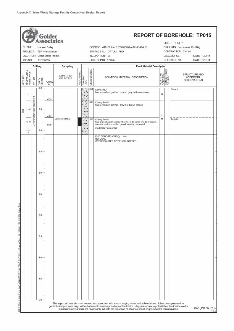
L
L-M
M-H
H
R
Silty SANDfine to medium grained, brown / grey, with some roots
Clayey SANDfine to medium grained, brown to brown orange
Clayey SANDfine grained, red / orange / brown, with some fine to medium,sub-rounded to rounded gravel, weakly cemented
moderately cemented
END OF BOREHOLE @ 1.10 mREFUSALGROUNDWATER NOT ENCOUNTERED
SM
SC
SC
0.30
0.70
0.90
AD
T
DS 0.70-0.90 m
Gro
undw
ater
not
enc
ount
ered
D
D -M
Topsoil
Laterite
SHEET: 1 OF 1
Field Material DescriptionSamplingDrilling
PE
NE
TRA
TIO
NR
ES
ISTA
NC
E
SOIL/ROCK MATERIAL DESCRIPTION
US
CS
SY
MB
OL
RE
CO
VE
RE
D
WA
TER
RLDEPTH
DE
PTH
(met
res)
ME
THO
D
GR
AP
HIC
LOG
SAMPLE ORFIELD TEST
DRILL RIG: Landcruiser Drill RigCONTRACTOR: Cardno
LOGGED: SECHECKED: AB
GAP gINT FN. F01aRL3
CLIENT:PROJECT:LOCATION:
JOB NO:
DATE: 13/2/14DATE: 6/11/14
This report of borehole must be read in conjunction with accompanying notes and abbreviations. It has been prepared forgeotechnical purposes only, without attempt to assess possible contamination. Any references to potential contamination are for
information only and do not necessarily indicate the presence or absence of soil or groundwater contamination.
REPORT OF BOREHOLE: TP015
Hansen BaileyTSF InvestigationChina Stone Project
137635015
COORDS: 419152.0 m E 7590250.0 m N MGA94 56
SURFACE RL: DATUM: AHDINCLINATION: -90°HOLE DEPTH: 1.10 m
GA
P 8
_08.
04 L
IB.G
LB L
og G
AP
NO
N-C
OR
ED
FU
LL P
AG
E G
INT.
GP
J <
<Dra
win
gFile
>> 1
0/11
/201
4 11
:56
8.3
0.00
4 D
atge
l Too
ls
MO
ISTU
RE
CO
ND
ITIO
NC
ON
SIS
TEN
CY
DE
NS
ITY
STRUCTURE ANDADDITIONAL
OBSERVATIONS
0.0
0.5
1.0
1.5
2.0
2.5
3.0
3.5
4.0
4.5
5.0
Appendix C | Mine Waste Storage Facility Conceptual Design Report

L
M-H
H
R
Silty SANDfine grained, brown / grey, with some roots
SANDfine grained, pale brown, with some clay, trace roots
Clayey SANDfine grained, pale brown / orange, trace fine to medium,sub-rounded to rounded gravel
with some fine to medium, sub-rounded to rounded gravel,weakly cemented
becoming red / brown
END OF BOREHOLE @ 2.00 mREFUSALGROUNDWATER NOT ENCOUNTERED
SM
SP
SC
0.30
0.70
0.90
1.10
AD
T
DS 0.30-0.70 m
DS 0.70-0.90 m
BDS 1.30-2.00 mGro
undw
ater
not
enc
ount
ered
D -M
D
Topsoil
Laterite
SHEET: 1 OF 1
Field Material DescriptionSamplingDrilling
PE
NE
TRA
TIO
NR
ES
ISTA
NC
E
SOIL/ROCK MATERIAL DESCRIPTION
US
CS
SY
MB
OL
RE
CO
VE
RE
D
WA
TER
RLDEPTH
DE
PTH
(met
res)
ME
THO
D
GR
AP
HIC
LOG
SAMPLE ORFIELD TEST
DRILL RIG: Landcruiser Drill RigCONTRACTOR: Cardno
LOGGED: SECHECKED: AB
GAP gINT FN. F01aRL3
CLIENT:PROJECT:LOCATION:
JOB NO:
DATE: 13/2/14DATE: 6/11/14
This report of borehole must be read in conjunction with accompanying notes and abbreviations. It has been prepared forgeotechnical purposes only, without attempt to assess possible contamination. Any references to potential contamination are for
information only and do not necessarily indicate the presence or absence of soil or groundwater contamination.
REPORT OF BOREHOLE: TP016
Hansen BaileyTSF InvestigationChina Stone Project
137635015
COORDS: 418458.0 m E 7589807.0 m N MGA94 56
SURFACE RL: DATUM: AHDINCLINATION: -90°HOLE DEPTH: 2.00 m
GA
P 8
_08.
04 L
IB.G
LB L
og G
AP
NO
N-C
OR
ED
FU
LL P
AG
E G
INT.
GP
J <
<Dra
win
gFile
>> 1
0/11
/201
4 11
:56
8.3
0.00
4 D
atge
l Too
ls
MO
ISTU
RE
CO
ND
ITIO
NC
ON
SIS
TEN
CY
DE
NS
ITY
STRUCTURE ANDADDITIONAL
OBSERVATIONS
0.0
0.5
1.0
1.5
2.0
2.5
3.0
3.5
4.0
4.5
5.0
Appendix C | Mine Waste Storage Facility Conceptual Design Report

L
M
H
R
Silty SANDfine to medium grained, brown, with some roots
Clayey SANDfine to medium grained, pale brown, trace roots
Sandy CLAYlow plasticity, brown / yellow and orange / red, fine grainedsand, trace cemented lenses
becomes sandy
becoming brown, orange and grey, with red pockets and tracefine to medium, sub-rounded gravel
TEST PIT DISCONTINUED @ 1.80 mREFUSALGROUNDWATER NOT ENCOUNTERED
SM
SC
CL
0.30
0.80
1.00
1.40
BH
DS 0.30-0.80 m
U50 1.20-1.45 m
BDS 1.40-1.80 m 1.45 mPP = 500 kPa
Gro
undw
ater
not
enc
ount
ered
M
D -M
M
L
H
SHEET: 1 OF 1
Field Material DescriptionSamplingExcavation
EX
CA
VATI
ON
RE
SIS
TAN
CE
SOIL/ROCK MATERIAL DESCRIPTION
US
CS
SY
MB
OL
RE
CO
VE
RE
D
WA
TER
RLDEPTH
DE
PTH
(met
res)
ME
THO
D
GR
AP
HIC
LOG
SAMPLE ORFIELD TEST
MACHINE: Cat 432ECONTRACTOR:
LOGGED: SECHECKED: AB
GAP gINT FN. F01fRL3
CLIENT:PROJECT:LOCATION:
JOB NO:
DATE: 7/2/14DATE: 6/11/14
This report of test pit must be read in conjunction with accompanying notes and abbreviations. It has been prepared forgeotechnical purposes only, without attempt to assess possible contamination. Any references to potential contamination are for
information only and do not necessarily indicate the presence or absence of soil or groundwater contamination.
REPORT OF TEST PIT: TP017
Hansen BaileyTSF InvestigationChina Stone Project
137635015
COORDS: 420521.0 m E 7590525.0 m N MGA94 56SURFACE RL: DATUM: AHD
PIT DEPTH: 1.80 mBUCKET TYPE: 450mm Standard
GA
P 8
_08.
04 L
IB.G
LB L
og G
AP
NO
N-C
OR
ED
FU
LL P
AG
E G
INT.
GP
J <
<Dra
win
gFile
>> 1
0/11
/201
4 11
:56
8.3
0.00
4 D
atge
l Too
ls
MO
ISTU
RE
CO
ND
ITIO
NC
ON
SIS
TEN
CY
DE
NS
ITY
DCP TEST (AS1289.6.3.2)Blows per 100 mm
5 10 15 200 25
HB
0.0
0.5
1.0
1.5
2.0
2.5
3.0
3.5
4.0
4.5
5.0
Appendix C | Mine Waste Storage Facility Conceptual Design Report

L
L-M
M-H
HR
Silty SANDfine to medium grained, brown / grey, with some roots
Sandy CLAYmedium plasticity, brown, fine grained sand, trace roots
becoming hard
becoming hard to drillCLAYmedium to high plasticity, pale brown to brown, with somefine to coarse gravel, well cementedEND OF BOREHOLE @ 1.00 mREFUSALGROUNDWATER NOT ENCOUNTERED
SM
CI
CI-CH
0.20
0.70
0.900.95
BH
DS 0.20-0.40 m
DS 0.70-0.90 m
DS 0.95-1.00 m
Gro
undw
ater
not
enc
ount
ered
D -M
M
D -M
D
H
Topsoil
SHEET: 1 OF 1
Field Material DescriptionSamplingDrilling
PE
NE
TRA
TIO
NR
ES
ISTA
NC
E
SOIL/ROCK MATERIAL DESCRIPTION
US
CS
SY
MB
OL
RE
CO
VE
RE
D
WA
TER
RLDEPTH
DE
PTH
(met
res)
ME
THO
D
GR
AP
HIC
LOG
SAMPLE ORFIELD TEST
DRILL RIG: Landcruiser Drill RigCONTRACTOR: Cardno
LOGGED: SECHECKED: AB
GAP gINT FN. F01aRL3
CLIENT:PROJECT:LOCATION:
JOB NO:
DATE: 13/2/14DATE: 6/11/14
This report of borehole must be read in conjunction with accompanying notes and abbreviations. It has been prepared forgeotechnical purposes only, without attempt to assess possible contamination. Any references to potential contamination are for
information only and do not necessarily indicate the presence or absence of soil or groundwater contamination.
REPORT OF BOREHOLE: TP018
Hansen BaileyTSF InvestigationChina Stone Project
137635015
COORDS: 419858.0 m E 7589990.0 m N MGA94 56
SURFACE RL: DATUM: AHDINCLINATION: -90°HOLE DEPTH: 1.00 m
GA
P 8
_08.
04 L
IB.G
LB L
og G
AP
NO
N-C
OR
ED
FU
LL P
AG
E G
INT.
GP
J <
<Dra
win
gFile
>> 1
0/11
/201
4 11
:56
8.3
0.00
4 D
atge
l Too
ls
MO
ISTU
RE
CO
ND
ITIO
NC
ON
SIS
TEN
CY
DE
NS
ITY
STRUCTURE ANDADDITIONAL
OBSERVATIONS
0.0
0.5
1.0
1.5
2.0
2.5
3.0
3.5
4.0
4.5
5.0
Appendix C | Mine Waste Storage Facility Conceptual Design Report

L
M
M-H
H
R
Silty SANDfine to medium grained, brown to dark brown, with some roots
Clayey SANDfine to medium grained, brown to pale brown, trace roots
fine grained, pale brown
trace fine to medium gravel, weakly cemented
moderately cemented
END OF BOREHOLE @ 1.90 mREFUSALGROUNDWATER NOT ENCOUNTERED
SM
SC0.30
0.50
0.80
1.60
AD
T
DS 1.30-1.60 m
Gro
undw
ater
not
enc
ount
ered
D -M
D
MD
D
VD
SHEET: 1 OF 1
Field Material DescriptionSamplingDrilling
PE
NE
TRA
TIO
NR
ES
ISTA
NC
E
SOIL/ROCK MATERIAL DESCRIPTION
US
CS
SY
MB
OL
RE
CO
VE
RE
D
WA
TER
RLDEPTH
DE
PTH
(met
res)
ME
THO
D
GR
AP
HIC
LOG
SAMPLE ORFIELD TEST
DRILL RIG: Landcruiser Drill RigCONTRACTOR: Cardno
LOGGED: SECHECKED: AB
GAP gINT FN. F01bRL3
CLIENT:PROJECT:LOCATION:
JOB NO:
DATE: 10/2/14DATE: 6/11/14
This report of borehole must be read in conjunction with accompanying notes and abbreviations. It has been prepared forgeotechnical purposes only, without attempt to assess possible contamination. Any references to potential contamination are for
information only and do not necessarily indicate the presence or absence of soil or groundwater contamination.
REPORT OF BOREHOLE: TP019
Hansen BaileyTSF InvestigationChina Stone Project
137635015
COORDS: 418668.0 m E 7589185.0 m N MGA94 56
SURFACE RL: DATUM: AHDINCLINATION: -90°HOLE DEPTH: 1.90 m
GA
P 8
_08.
04 L
IB.G
LB L
og G
AP
NO
N-C
OR
ED
FU
LL P
AG
E G
INT.
GP
J <
<Dra
win
gFile
>> 1
0/11
/201
4 11
:56
8.3
0.00
4 D
atge
l Too
ls
MO
ISTU
RE
CO
ND
ITIO
NC
ON
SIS
TEN
CY
DE
NS
ITY
DCP TEST (AS1289.6.3.2)Blows per 100 mm
5 10 15 200 25
HB
0.0
0.5
1.0
1.5
2.0
2.5
3.0
3.5
4.0
4.5
5.0
Appendix C | Mine Waste Storage Facility Conceptual Design Report

L
H
R
Silty SANDbrown / grey, and roots
SANDfine to medium grained, pale brown to pale orange, with someclay, and roots
Clayey SANDfine grained, pale brown, pale grey and pale orange, traceclay, and roots
TEST PIT DISCONTINUED @ 1.40 mREFUSALGROUNDWATER NOT ENCOUNTERED
SM
SP
SC
0.30
0.90
BH
DS 0.30-1.20 m
DS 1.20-1.40 m
Gro
undw
ater
not
enc
ount
ered
D
L
D
VD
SHEET: 1 OF 1
Field Material DescriptionSamplingExcavation
EX
CA
VATI
ON
RE
SIS
TAN
CE
SOIL/ROCK MATERIAL DESCRIPTION
US
CS
SY
MB
OL
RE
CO
VE
RE
D
WA
TER
RLDEPTH
DE
PTH
(met
res)
ME
THO
D
GR
AP
HIC
LOG
SAMPLE ORFIELD TEST
MACHINE: Cat 432ECONTRACTOR:
LOGGED: SECHECKED: AB
GAP gINT FN. F01fRL3
CLIENT:PROJECT:LOCATION:
JOB NO:
DATE: 7/2/14DATE: 6/11/14
This report of test pit must be read in conjunction with accompanying notes and abbreviations. It has been prepared forgeotechnical purposes only, without attempt to assess possible contamination. Any references to potential contamination are for
information only and do not necessarily indicate the presence or absence of soil or groundwater contamination.
REPORT OF TEST PIT: TP020
Hansen BaileyTSF InvestigationChina Stone Project
137635015
COORDS: 420680.0 m E 7590120.0 m N MGA94 56SURFACE RL: DATUM: AHD
PIT DEPTH: 1.40 mBUCKET TYPE: 450mm Standard
GA
P 8
_08.
04 L
IB.G
LB L
og G
AP
NO
N-C
OR
ED
FU
LL P
AG
E G
INT.
GP
J <
<Dra
win
gFile
>> 1
0/11
/201
4 11
:56
8.3
0.00
4 D
atge
l Too
ls
MO
ISTU
RE
CO
ND
ITIO
NC
ON
SIS
TEN
CY
DE
NS
ITY
DCP TEST (AS1289.6.3.2)Blows per 100 mm
5 10 15 200 25
HB
0.0
0.5
1.0
1.5
2.0
2.5
3.0
3.5
4.0
4.5
5.0
Appendix C | Mine Waste Storage Facility Conceptual Design Report

L
M-H
H
R
Sandy SILTlow liquid limit, brown and grey, fine with some roots
Sandy CLAYlow plasticity, pale brown and pale grey, weakly cemented
becoming moderately cemented, pale brown, pale grey andgrey / white, with red / black pockets
with some sand lenses (fine grained)
TEST PIT DISCONTINUED @ 1.40 mREFUSALGROUNDWATER NOT ENCOUNTERED
ML
CL0.30
0.70
1.00
BH
DS 0.30-0.60 m
DS 1.20-1.40 m
Gro
undw
ater
not
enc
ount
ered
M
D -M
M
St
VSt
H
SHEET: 1 OF 1
Field Material DescriptionSamplingExcavation
EX
CA
VATI
ON
RE
SIS
TAN
CE
SOIL/ROCK MATERIAL DESCRIPTION
US
CS
SY
MB
OL
RE
CO
VE
RE
D
WA
TER
RLDEPTH
DE
PTH
(met
res)
ME
THO
D
GR
AP
HIC
LOG
SAMPLE ORFIELD TEST
MACHINE: Cat 432ECONTRACTOR:
LOGGED: SECHECKED: AB
GAP gINT FN. F01fRL3
CLIENT:PROJECT:LOCATION:
JOB NO:
DATE: 7/2/14DATE: 6/11/14
This report of test pit must be read in conjunction with accompanying notes and abbreviations. It has been prepared forgeotechnical purposes only, without attempt to assess possible contamination. Any references to potential contamination are for
information only and do not necessarily indicate the presence or absence of soil or groundwater contamination.
REPORT OF TEST PIT: TP021
Hansen BaileyTSF InvestigationChina Stone Project
137635015
COORDS: 420262.0 m E 7590097.0 m N MGA94 56SURFACE RL: DATUM: AHD
PIT DEPTH: 1.40 mBUCKET TYPE: 450mm Standard
GA
P 8
_08.
04 L
IB.G
LB L
og G
AP
NO
N-C
OR
ED
FU
LL P
AG
E G
INT.
GP
J <
<Dra
win
gFile
>> 1
0/11
/201
4 11
:56
8.3
0.00
4 D
atge
l Too
ls
MO
ISTU
RE
CO
ND
ITIO
NC
ON
SIS
TEN
CY
DE
NS
ITY
DCP TEST (AS1289.6.3.2)Blows per 100 mm
5 10 15 200 25
0.0
0.5
1.0
1.5
2.0
2.5
3.0
3.5
4.0
4.5
5.0
Appendix C | Mine Waste Storage Facility Conceptual Design Report

L
H
H-R
R
Sandy SILTfine, low liquid limit, brown, with some roots
Sandy CLAYlow plasticity, pale brown, pale grey and red, fine grainedsand, moderately cemented with well cemented pockets
TEST PIT DISCONTINUED @ 1.00 mREFUSALGROUNDWATER NOT ENCOUNTERED
ML
CL0.40
BH
DS 0.40-0.60 m
Gro
undw
ater
not
enc
ount
ered M
D
VSt
H
SHEET: 1 OF 1
Field Material DescriptionSamplingExcavation
EX
CA
VATI
ON
RE
SIS
TAN
CE
SOIL/ROCK MATERIAL DESCRIPTION
US
CS
SY
MB
OL
RE
CO
VE
RE
D
WA
TER
RLDEPTH
DE
PTH
(met
res)
ME
THO
D
GR
AP
HIC
LOG
SAMPLE ORFIELD TEST
MACHINE: Cat 432ECONTRACTOR:
LOGGED: SECHECKED: AB
GAP gINT FN. F01fRL3
CLIENT:PROJECT:LOCATION:
JOB NO:
DATE: 7/2/14DATE: 6/11/14
This report of test pit must be read in conjunction with accompanying notes and abbreviations. It has been prepared forgeotechnical purposes only, without attempt to assess possible contamination. Any references to potential contamination are for
information only and do not necessarily indicate the presence or absence of soil or groundwater contamination.
REPORT OF TEST PIT: TP022
Hansen BaileyTSF InvestigationChina Stone Project
137635015
COORDS: 420063.0 m E 7589963.0 m N MGA94 56SURFACE RL: DATUM: AHD
PIT DEPTH: 1.00 mBUCKET TYPE: 450mm Standard
GA
P 8
_08.
04 L
IB.G
LB L
og G
AP
NO
N-C
OR
ED
FU
LL P
AG
E G
INT.
GP
J <
<Dra
win
gFile
>> 1
0/11
/201
4 11
:56
8.3
0.00
4 D
atge
l Too
ls
MO
ISTU
RE
CO
ND
ITIO
NC
ON
SIS
TEN
CY
DE
NS
ITY
DCP TEST (AS1289.6.3.2)Blows per 100 mm
5 10 15 200 25
0.0
0.5
1.0
1.5
2.0
2.5
3.0
3.5
4.0
4.5
5.0
Appendix C | Mine Waste Storage Facility Conceptual Design Report

L
M
H
H-R
R
Silty SANDfine to medium grained, brown, with some roots
Clayey SANDfine grained, pale brown, trace roots, weakly cemented
becomes moderately cemented
Clayey SANDfine grained, pale grey and pale brown with some red pockets,medium plasticity clay, trace fine to medium, sub-rounded torounded gravel
TEST PIT DISCONTINUED @ 1.70 mREFUSALGROUNDWATER NOT ENCOUNTERED
SM
SC
SC
0.40
1.00
1.30
BH
DS 0.40-0.70 m
BDS 1.30-1.60 m
BDS 1.80-2.00 m(collected fromadjacent streamcutting)
Gro
undw
ater
not
enc
ount
ered
M
D -M
D
L
VD
SHEET: 1 OF 1
Field Material DescriptionSamplingExcavation
EX
CA
VATI
ON
RE
SIS
TAN
CE
SOIL/ROCK MATERIAL DESCRIPTION
US
CS
SY
MB
OL
RE
CO
VE
RE
D
WA
TER
RLDEPTH
DE
PTH
(met
res)
ME
THO
D
GR
AP
HIC
LOG
SAMPLE ORFIELD TEST
MACHINE: Cat 432ECONTRACTOR:
LOGGED: SECHECKED: AB
GAP gINT FN. F01fRL3
CLIENT:PROJECT:LOCATION:
JOB NO:
DATE: 7/2/14DATE: 6/11/14
This report of test pit must be read in conjunction with accompanying notes and abbreviations. It has been prepared forgeotechnical purposes only, without attempt to assess possible contamination. Any references to potential contamination are for
information only and do not necessarily indicate the presence or absence of soil or groundwater contamination.
REPORT OF TEST PIT: TP023
Hansen BaileyTSF InvestigationChina Stone Project
137635015
COORDS: 420977.0 m E 7589930.0 m N MGA94 56SURFACE RL: DATUM: AHD
PIT DEPTH: 1.70 mBUCKET TYPE: 450mm Standard
GA
P 8
_08.
04 L
IB.G
LB L
og G
AP
NO
N-C
OR
ED
FU
LL P
AG
E G
INT.
GP
J <
<Dra
win
gFile
>> 1
0/11
/201
4 11
:56
8.3
0.00
4 D
atge
l Too
ls
MO
ISTU
RE
CO
ND
ITIO
NC
ON
SIS
TEN
CY
DE
NS
ITY
DCP TEST (AS1289.6.3.2)Blows per 100 mm
5 10 15 200 25
HB
0.0
0.5
1.0
1.5
2.0
2.5
3.0
3.5
4.0
4.5
5.0
Appendix C | Mine Waste Storage Facility Conceptual Design Report

L
L-M
M
Silty SANDfine to medium grained, brown, trace clay, with some roots
Clayey SANDfine to medium grained, pale brown orange, trace roots
trace fine to medium, sub-rounded red gravel, with no roots,becomes weakly cemented
trace moderately cemented lenses
TEST PIT DISCONTINUED @ 3.00 mREFUSALGROUNDWATER NOT ENCOUNTERED
SM
SC0.50
1.00
1.90
BH
DS 1.00-1.30 m
DS 1.40-1.80 m
DS 2.00-2.30 m
DS 2.70-3.00 m
Gro
undw
ater
not
enc
ount
ered
D -M
L
VD
SHEET: 1 OF 1
Field Material DescriptionSamplingExcavation
EX
CA
VATI
ON
RE
SIS
TAN
CE
SOIL/ROCK MATERIAL DESCRIPTION
US
CS
SY
MB
OL
RE
CO
VE
RE
D
WA
TER
RLDEPTH
DE
PTH
(met
res)
ME
THO
D
GR
AP
HIC
LOG
SAMPLE ORFIELD TEST
MACHINE: Cat 432ECONTRACTOR:
LOGGED: SECHECKED: AB
GAP gINT FN. F01fRL3
CLIENT:PROJECT:LOCATION:
JOB NO:
DATE: 7/2/14DATE: 6/11/14
This report of test pit must be read in conjunction with accompanying notes and abbreviations. It has been prepared forgeotechnical purposes only, without attempt to assess possible contamination. Any references to potential contamination are for
information only and do not necessarily indicate the presence or absence of soil or groundwater contamination.
REPORT OF TEST PIT: TP024
Hansen BaileyTSF InvestigationChina Stone Project
137635015
COORDS: 420310.0 m E 7589730.0 m N MGA94 56SURFACE RL: DATUM: AHD
PIT DEPTH: 3.00 mBUCKET TYPE: 450mm Standard
GA
P 8
_08.
04 L
IB.G
LB L
og G
AP
NO
N-C
OR
ED
FU
LL P
AG
E G
INT.
GP
J <
<Dra
win
gFile
>> 1
0/11
/201
4 11
:56
8.3
0.00
4 D
atge
l Too
ls
MO
ISTU
RE
CO
ND
ITIO
NC
ON
SIS
TEN
CY
DE
NS
ITY
DCP TEST (AS1289.6.3.2)Blows per 100 mm
5 10 15 200 25
0.0
0.5
1.0
1.5
2.0
2.5
3.0
3.5
4.0
4.5
5.0
Appendix C | Mine Waste Storage Facility Conceptual Design Report

L
L-M
M
H
R
Silty SANDfine to medium grained, brown, with some roots
pale brown, trace roots
Clayey SANDfine grained, pale brown, pale grey, with pockets of orange /red, with some silt, with some clay, weakly cementedwith some fine to medium, sub-rounded to rounded, red gravel
Sandy CLAYmedium plasticity, grey / brown and red / brown, with somefine grained sand, with some red gravelTEST PIT DISCONTINUED @ 1.70 mREFUSALGROUNDWATER NOT ENCOUNTERED
SM
SC
CI
0.50
0.90
1.10
1.50
BH
DS 0.00-0.50 m
DS 1.30-1.50 m
DS 1.50-1.70 m
Gro
undw
ater
not
enc
ount
ered
M
D -M
L
D
VD
H
SHEET: 1 OF 1
Field Material DescriptionSamplingExcavation
EX
CA
VATI
ON
RE
SIS
TAN
CE
SOIL/ROCK MATERIAL DESCRIPTION
US
CS
SY
MB
OL
RE
CO
VE
RE
D
WA
TER
RLDEPTH
DE
PTH
(met
res)
ME
THO
D
GR
AP
HIC
LOG
SAMPLE ORFIELD TEST
MACHINE: Cat 432ECONTRACTOR:
LOGGED: SECHECKED: AB
GAP gINT FN. F01fRL3
CLIENT:PROJECT:LOCATION:
JOB NO:
DATE: 7/2/14DATE: 6/11/14
This report of test pit must be read in conjunction with accompanying notes and abbreviations. It has been prepared forgeotechnical purposes only, without attempt to assess possible contamination. Any references to potential contamination are for
information only and do not necessarily indicate the presence or absence of soil or groundwater contamination.
REPORT OF TEST PIT: TP025
Hansen BaileyTSF InvestigationChina Stone Project
137635015
COORDS: 420028.0 m E 7589472.0 m N MGA94 56SURFACE RL: DATUM: AHD
PIT DEPTH: 1.70 mBUCKET TYPE: 450mm Standard
GA
P 8
_08.
04 L
IB.G
LB L
og G
AP
NO
N-C
OR
ED
FU
LL P
AG
E G
INT.
GP
J <
<Dra
win
gFile
>> 1
0/11
/201
4 11
:56
8.3
0.00
4 D
atge
l Too
ls
MO
ISTU
RE
CO
ND
ITIO
NC
ON
SIS
TEN
CY
DE
NS
ITY
DCP TEST (AS1289.6.3.2)Blows per 100 mm
5 10 15 200 25
0.0
0.5
1.0
1.5
2.0
2.5
3.0
3.5
4.0
4.5
5.0
Appendix C | Mine Waste Storage Facility Conceptual Design Report

L
M
M-H
H
R
Sandy SILTlow liquid limit, brown, fine with some roots
Clayey SANDfine grained, pale brown, trace roots
weakly cemented, trace fine to coarse, sub-rounded gravel
becomes brown / orange / grey, with some medium plasticityclay
TEST PIT DISCONTINUED @ 2.00 mREFUSALGROUNDWATER NOT ENCOUNTERED
ML
SC0.40
1.50
1.70
BH
DS 0.00-0.40 m
DS 0.40-0.80 m
DS 1.50-1.70 m
BDS 1.70-2.00 mDS 1.70-1.90 m
Gro
undw
ater
not
enc
ount
ered
M
D -M
F -St
D
VD
SHEET: 1 OF 1
Field Material DescriptionSamplingExcavation
EX
CA
VATI
ON
RE
SIS
TAN
CE
SOIL/ROCK MATERIAL DESCRIPTION
US
CS
SY
MB
OL
RE
CO
VE
RE
D
WA
TER
RLDEPTH
DE
PTH
(met
res)
ME
THO
D
GR
AP
HIC
LOG
SAMPLE ORFIELD TEST
MACHINE: Cat 432ECONTRACTOR:
LOGGED: SECHECKED: AB
GAP gINT FN. F01fRL3
CLIENT:PROJECT:LOCATION:
JOB NO:
DATE: 7/2/14DATE: 6/11/14
This report of test pit must be read in conjunction with accompanying notes and abbreviations. It has been prepared forgeotechnical purposes only, without attempt to assess possible contamination. Any references to potential contamination are for
information only and do not necessarily indicate the presence or absence of soil or groundwater contamination.
REPORT OF TEST PIT: TP026
Hansen BaileyTSF InvestigationChina Stone Project
137635015
COORDS: 420650.0 m E 7589577.0 m N MGA94 56SURFACE RL: DATUM: AHD
PIT DEPTH: 2.00 mBUCKET TYPE: 450mm Standard
GA
P 8
_08.
04 L
IB.G
LB L
og G
AP
NO
N-C
OR
ED
FU
LL P
AG
E G
INT.
GP
J <
<Dra
win
gFile
>> 1
0/11
/201
4 11
:56
8.3
0.00
4 D
atge
l Too
ls
MO
ISTU
RE
CO
ND
ITIO
NC
ON
SIS
TEN
CY
DE
NS
ITY
DCP TEST (AS1289.6.3.2)Blows per 100 mm
5 10 15 200 25
HB
0.0
0.5
1.0
1.5
2.0
2.5
3.0
3.5
4.0
4.5
5.0
Appendix C | Mine Waste Storage Facility Conceptual Design Report

L
L-M
M-H
Silty SANDfine grained, brown grey, with some roots
Clayey SANDfine to medium grained, brown to pale brown, trace roots
Clayey SANDfine to medium grained, brown to red brown, with some fine tomedium, sub-rounded to rounded gravel, weakly cemented
moderately cemented
END OF BOREHOLE @ 1.30 mREFUSALGROUNDWATER NOT ENCOUNTERED
SM
SC
SC
0.30
0.50
1.00
AD
T
DS 0.50-0.90 m
DS 1.00-1.30 m
Gro
undw
ater
not
enc
ount
ered
D -M
D
Topsoil
SHEET: 1 OF 1
Field Material DescriptionSamplingDrilling
PE
NE
TRA
TIO
NR
ES
ISTA
NC
E
SOIL/ROCK MATERIAL DESCRIPTION
US
CS
SY
MB
OL
RE
CO
VE
RE
D
WA
TER
RLDEPTH
DE
PTH
(met
res)
ME
THO
D
GR
AP
HIC
LOG
SAMPLE ORFIELD TEST
DRILL RIG: Landcruiser Drill RigCONTRACTOR: Cardno
LOGGED: SECHECKED: AB
GAP gINT FN. F01aRL3
CLIENT:PROJECT:LOCATION:
JOB NO:
DATE: 13/2/14DATE: 6/11/14
This report of borehole must be read in conjunction with accompanying notes and abbreviations. It has been prepared forgeotechnical purposes only, without attempt to assess possible contamination. Any references to potential contamination are for
information only and do not necessarily indicate the presence or absence of soil or groundwater contamination.
REPORT OF BOREHOLE: TP027
Hansen BaileyTSF InvestigationChina Stone Project
137635015
COORDS: 418398.0 m E 7590904.0 m N MGA94 56
SURFACE RL: DATUM: AHDINCLINATION: -90°HOLE DEPTH: 1.30 m
GA
P 8
_08.
04 L
IB.G
LB L
og G
AP
NO
N-C
OR
ED
FU
LL P
AG
E G
INT.
GP
J <
<Dra
win
gFile
>> 1
0/11
/201
4 11
:56
8.3
0.00
4 D
atge
l Too
ls
MO
ISTU
RE
CO
ND
ITIO
NC
ON
SIS
TEN
CY
DE
NS
ITY
STRUCTURE ANDADDITIONAL
OBSERVATIONS
0.0
0.5
1.0
1.5
2.0
2.5
3.0
3.5
4.0
4.5
5.0
Appendix C | Mine Waste Storage Facility Conceptual Design Report

L
L-M
L
H
R
Silty SANDfine to medium grained, brown to brown / red
Sandy CLAYmedium plasticity, red / brown and grey, with some silt
becomes red / brown / yellow
Clayey SANDfine to medium grained, grey, medium plasticity claySandy CLAYmedium plasticity, red, grey and orange / brown
TEST PIT DISCONTINUED @ 1.80 mREFUSALGROUNDWATER ENCOUNTERED @ 1.40 m DEPTH
SM
CI
SC
CI
0.40
0.90
1.40
1.50
BH
DS 0.40-0.90 m
U50 0.80-0.90 m
DS 1.30-1.70 m
U50 1.70-1.95 m
08/0
2/14
M
W
D -M
MD
St -VSt
MD
VSt
SHEET: 1 OF 1
Field Material DescriptionSamplingExcavation
EX
CA
VATI
ON
RE
SIS
TAN
CE
SOIL/ROCK MATERIAL DESCRIPTION
US
CS
SY
MB
OL
RE
CO
VE
RE
D
WA
TER
RLDEPTH
DE
PTH
(met
res)
ME
THO
D
GR
AP
HIC
LOG
SAMPLE ORFIELD TEST
MACHINE: Cat 432ECONTRACTOR:
LOGGED: SECHECKED: AB
GAP gINT FN. F01fRL3
CLIENT:PROJECT:LOCATION:
JOB NO:
DATE: 8/2/14DATE: 6/11/14
This report of test pit must be read in conjunction with accompanying notes and abbreviations. It has been prepared forgeotechnical purposes only, without attempt to assess possible contamination. Any references to potential contamination are for
information only and do not necessarily indicate the presence or absence of soil or groundwater contamination.
REPORT OF TEST PIT: TP028
Hansen BaileyTSF InvestigationChina Stone Project
137635015
COORDS: 417751.0 m E 7592439.0 m N MGA94 56SURFACE RL: DATUM: AHD
PIT DEPTH: 1.80 mBUCKET TYPE: 450mm Standard
GA
P 8
_08.
04 L
IB.G
LB L
og G
AP
NO
N-C
OR
ED
FU
LL P
AG
E G
INT.
GP
J <
<Dra
win
gFile
>> 1
0/11
/201
4 11
:56
8.3
0.00
4 D
atge
l Too
ls
MO
ISTU
RE
CO
ND
ITIO
NC
ON
SIS
TEN
CY
DE
NS
ITY
DCP TEST (AS1289.6.3.2)Blows per 100 mm
5 10 15 200 25
HB
0.0
0.5
1.0
1.5
2.0
2.5
3.0
3.5
4.0
4.5
5.0
Appendix C | Mine Waste Storage Facility Conceptual Design Report

L
L-M
L
Silty SANDfine to medium grained, brown, with some roots
Sandy CLAYlow plasticity, pale brown to brown, fine grained sand, friable,with trace roots
trace sandy lenses and roots
Clayey SANDfine to medium grained, pale brown
with some coarse grained sand
TEST PIT DISCONTINUED @ 3.50 mGROUNDWATER NOT ENCOUNTEREDPit walls remained stable after being left open for 5 minutes
SM
CL
SC
0.30
1.00
1.30
2.00
BH
DS 0.40-0.60 m
DS 1.30-1.70 m
DS 2.50-3.00 m
Gro
undw
ater
not
enc
ount
ered
M
D
MD
St -VSt
D
SHEET: 1 OF 1
Field Material DescriptionSamplingExcavation
EX
CA
VATI
ON
RE
SIS
TAN
CE
SOIL/ROCK MATERIAL DESCRIPTION
US
CS
SY
MB
OL
RE
CO
VE
RE
D
WA
TER
RLDEPTH
DE
PTH
(met
res)
ME
THO
D
GR
AP
HIC
LOG
SAMPLE ORFIELD TEST
MACHINE: Cat 432ECONTRACTOR:
LOGGED: SECHECKED: AB
GAP gINT FN. F01fRL3
CLIENT:PROJECT:LOCATION:
JOB NO:
DATE: 8/2/14DATE: 6/11/14
This report of test pit must be read in conjunction with accompanying notes and abbreviations. It has been prepared forgeotechnical purposes only, without attempt to assess possible contamination. Any references to potential contamination are for
information only and do not necessarily indicate the presence or absence of soil or groundwater contamination.
REPORT OF TEST PIT: TP029
Hansen BaileyTSF InvestigationChina Stone Project
137635015
COORDS: 417661.0 m E 7591876.0 m N MGA94 56SURFACE RL: DATUM: AHD
PIT DEPTH: 3.50 mBUCKET TYPE: 450mm Standard
GA
P 8
_08.
04 L
IB.G
LB L
og G
AP
NO
N-C
OR
ED
FU
LL P
AG
E G
INT.
GP
J <
<Dra
win
gFile
>> 1
0/11
/201
4 11
:56
8.3
0.00
4 D
atge
l Too
ls
MO
ISTU
RE
CO
ND
ITIO
NC
ON
SIS
TEN
CY
DE
NS
ITY
DCP TEST (AS1289.6.3.2)Blows per 100 mm
5 10 15 200 25
0.0
0.5
1.0
1.5
2.0
2.5
3.0
3.5
4.0
4.5
5.0
Appendix C | Mine Waste Storage Facility Conceptual Design Report

L
L-M
M
M-H
H
R
Silty SANDfine grained, brown, with some roots
Clayey SANDfine grained, brown / grey, trace roots
pale brown / yellow, weakly cemented
with some red / orange pockets
Clayey SANDfine grained, grey and grey / white with red pockets, withsome fine to coarse, sub-rounded to rounded gravel, traceclay, moderately cemented
with black and red pockets
TEST PIT DISCONTINUED @ 1.60 mREFUSALGROUNDWATER NOT ENCOUNTERED
SM
SC
SC
0.20
0.40
0.80
1.10
1.40
BH
DS 0.80-1.00 m
DS 1.10-1.30 mGro
undw
ater
not
enc
ount
ered
D -M
D
L
VD
SHEET: 1 OF 1
Field Material DescriptionSamplingExcavation
EX
CA
VATI
ON
RE
SIS
TAN
CE
SOIL/ROCK MATERIAL DESCRIPTION
US
CS
SY
MB
OL
RE
CO
VE
RE
D
WA
TER
RLDEPTH
DE
PTH
(met
res)
ME
THO
D
GR
AP
HIC
LOG
SAMPLE ORFIELD TEST
MACHINE: Cat 432ECONTRACTOR:
LOGGED: SECHECKED: AB
GAP gINT FN. F01fRL3
CLIENT:PROJECT:LOCATION:
JOB NO:
DATE: 8/2/14DATE: 6/11/14
This report of test pit must be read in conjunction with accompanying notes and abbreviations. It has been prepared forgeotechnical purposes only, without attempt to assess possible contamination. Any references to potential contamination are for
information only and do not necessarily indicate the presence or absence of soil or groundwater contamination.
REPORT OF TEST PIT: TP030
Hansen BaileyTSF InvestigationChina Stone Project
137635015
COORDS: 417475.0 m E 7590428.0 m N MGA94 56SURFACE RL: DATUM: AHD
PIT DEPTH: 1.60 mBUCKET TYPE: 450mm Standard
GA
P 8
_08.
04 L
IB.G
LB L
og G
AP
NO
N-C
OR
ED
FU
LL P
AG
E G
INT.
GP
J <
<Dra
win
gFile
>> 1
0/11
/201
4 11
:56
8.3
0.00
4 D
atge
l Too
ls
MO
ISTU
RE
CO
ND
ITIO
NC
ON
SIS
TEN
CY
DE
NS
ITY
DCP TEST (AS1289.6.3.2)Blows per 100 mm
5 10 15 200 25
0.0
0.5
1.0
1.5
2.0
2.5
3.0
3.5
4.0
4.5
5.0
Appendix C | Mine Waste Storage Facility Conceptual Design Report
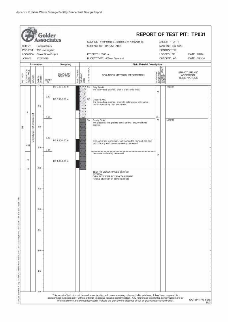
L
M-H
H
R
Silty SANDfine to medium grained, brown, with some roots
Clayey SANDfine to medium grained, brown to pale brown, with somemedium plasticity clay, trace roots
Sandy CLAYlow plasticity, fine grained sand, yellow / brown with redpockets
with some fine to medium, sub-rounded to rounded, red andred / black gravel, becomes weakly cemented
becomes moderately cemented
TEST PIT DISCONTINUED @ 2.05 mREFUSALGROUNDWATER NOT ENCOUNTEREDRefusal at 2.05 m on cemented beds
SM
SC
CL
0.30
0.80
1.30
1.60
BH
DS 0.00-0.30 m
DS 0.30-0.80 m
DS 1.30-1.60 m
DS 1.80-2.00 m
Gro
undw
ater
not
enc
ount
ered
M
D -M
D
Topsoil
Laterite
SHEET: 1 OF 1
Field Material DescriptionSamplingExcavation
EX
CA
VATI
ON
RE
SIS
TAN
CE
SOIL/ROCK MATERIAL DESCRIPTION
US
CS
SY
MB
OL
RE
CO
VE
RE
D
WA
TER
RLDEPTH
DE
PTH
(met
res)
ME
THO
D
GR
AP
HIC
LOG
SAMPLE ORFIELD TEST
MACHINE: Cat 432ECONTRACTOR:
LOGGED: SECHECKED: AB
GAP gINT FN. F01eRL3
CLIENT:PROJECT:LOCATION:
JOB NO:
DATE: 9/2/14DATE: 6/11/14
This report of test pit must be read in conjunction with accompanying notes and abbreviations. It has been prepared forgeotechnical purposes only, without attempt to assess possible contamination. Any references to potential contamination are for
information only and do not necessarily indicate the presence or absence of soil or groundwater contamination.
REPORT OF TEST PIT: TP031
Hansen BaileyTSF InvestigationChina Stone Project
137635015
COORDS: 419440.0 m E 7588975.0 m N MGA94 56SURFACE RL: DATUM: AHD
PIT DEPTH: 2.05 mBUCKET TYPE: 450mm Standard
GA
P 8
_08.
04 L
IB.G
LB L
og G
AP
NO
N-C
OR
ED
FU
LL P
AG
E G
INT.
GP
J <
<Dra
win
gFile
>> 1
0/11
/201
4 11
:56
8.3
0.00
4 D
atge
l Too
ls
MO
ISTU
RE
CO
ND
ITIO
NC
ON
SIS
TEN
CY
DE
NS
ITY
STRUCTURE ANDADDITIONAL
OBSERVATIONS
0.0
0.5
1.0
1.5
2.0
2.5
3.0
3.5
4.0
4.5
5.0
Appendix C | Mine Waste Storage Facility Conceptual Design Report
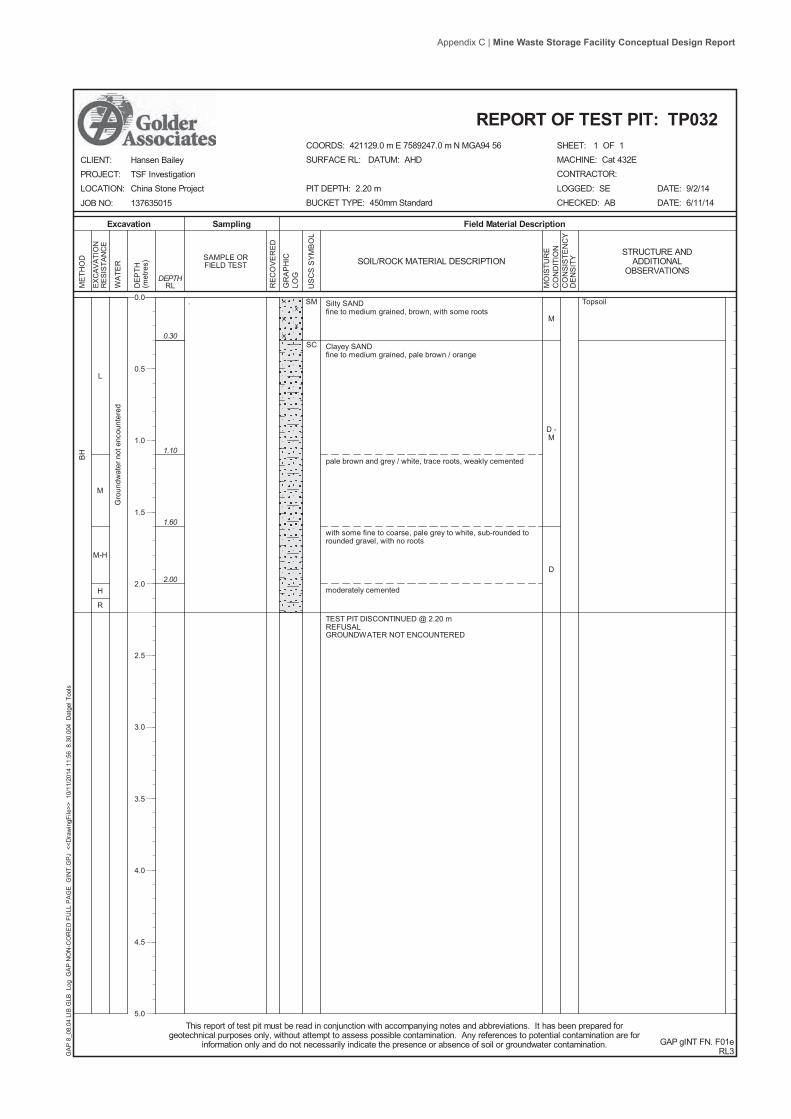
L
M
M-H
H
R
Silty SANDfine to medium grained, brown, with some roots
Clayey SANDfine to medium grained, pale brown / orange
pale brown and grey / white, trace roots, weakly cemented
with some fine to coarse, pale grey to white, sub-rounded torounded gravel, with no roots
moderately cemented
TEST PIT DISCONTINUED @ 2.20 mREFUSALGROUNDWATER NOT ENCOUNTERED
SM
SC0.30
1.10
1.60
2.00
BH
.
Gro
undw
ater
not
enc
ount
ered
M
D -M
D
Topsoil
SHEET: 1 OF 1
Field Material DescriptionSamplingExcavation
EX
CA
VATI
ON
RE
SIS
TAN
CE
SOIL/ROCK MATERIAL DESCRIPTION
US
CS
SY
MB
OL
RE
CO
VE
RE
D
WA
TER
RLDEPTH
DE
PTH
(met
res)
ME
THO
D
GR
AP
HIC
LOG
SAMPLE ORFIELD TEST
MACHINE: Cat 432ECONTRACTOR:
LOGGED: SECHECKED: AB
GAP gINT FN. F01eRL3
CLIENT:PROJECT:LOCATION:
JOB NO:
DATE: 9/2/14DATE: 6/11/14
This report of test pit must be read in conjunction with accompanying notes and abbreviations. It has been prepared forgeotechnical purposes only, without attempt to assess possible contamination. Any references to potential contamination are for
information only and do not necessarily indicate the presence or absence of soil or groundwater contamination.
REPORT OF TEST PIT: TP032
Hansen BaileyTSF InvestigationChina Stone Project
137635015
COORDS: 421129.0 m E 7589247.0 m N MGA94 56SURFACE RL: DATUM: AHD
PIT DEPTH: 2.20 mBUCKET TYPE: 450mm Standard
GA
P 8
_08.
04 L
IB.G
LB L
og G
AP
NO
N-C
OR
ED
FU
LL P
AG
E G
INT.
GP
J <
<Dra
win
gFile
>> 1
0/11
/201
4 11
:56
8.3
0.00
4 D
atge
l Too
ls
MO
ISTU
RE
CO
ND
ITIO
NC
ON
SIS
TEN
CY
DE
NS
ITY
STRUCTURE ANDADDITIONAL
OBSERVATIONS
0.0
0.5
1.0
1.5
2.0
2.5
3.0
3.5
4.0
4.5
5.0
Appendix C | Mine Waste Storage Facility Conceptual Design Report

L
L-M
M
H
R
Silty SANDfine to medium grained, brown to brown / orange, trace clay,with some roots
SANDfine to medium grained, orange / brown, with some silt, traceroots
trace fine to medium, sub-rounded to rounded gravel, with noroots
with no gravel
with some fine to coarse, sub-angular to sub-rounded red /black / grey gravelbecomes moderately cementedTEST PIT DISCONTINUED @ 2.50 mREFUSALGROUNDWATER NOT ENCOUNTEREDPit walls were unstable between 0.4 and 1.3 m depth
SM
SP0.40
1.50
2.00
2.30
2.40
BH
DS 1.30-1.50 m
DS 2.00-2.30 m
Gro
undw
ater
not
enc
ount
ered
M
D
L
D
VD
SHEET: 1 OF 1
Field Material DescriptionSamplingExcavation
EX
CA
VATI
ON
RE
SIS
TAN
CE
SOIL/ROCK MATERIAL DESCRIPTION
US
CS
SY
MB
OL
RE
CO
VE
RE
D
WA
TER
RLDEPTH
DE
PTH
(met
res)
ME
THO
D
GR
AP
HIC
LOG
SAMPLE ORFIELD TEST
MACHINE: Cat 432ECONTRACTOR:
LOGGED: SECHECKED: AB
GAP gINT FN. F01fRL3
CLIENT:PROJECT:LOCATION:
JOB NO:
DATE: 9/2/14DATE: 6/11/14
This report of test pit must be read in conjunction with accompanying notes and abbreviations. It has been prepared forgeotechnical purposes only, without attempt to assess possible contamination. Any references to potential contamination are for
information only and do not necessarily indicate the presence or absence of soil or groundwater contamination.
REPORT OF TEST PIT: TP033
Hansen BaileyTSF InvestigationChina Stone Project
137635015
COORDS: 420998.0 m E 7590282.0 m N MGA94 56SURFACE RL: DATUM: AHD
PIT DEPTH: 2.50 mBUCKET TYPE: 450mm Standard
GA
P 8
_08.
04 L
IB.G
LB L
og G
AP
NO
N-C
OR
ED
FU
LL P
AG
E G
INT.
GP
J <
<Dra
win
gFile
>> 1
0/11
/201
4 11
:56
8.3
0.00
4 D
atge
l Too
ls
MO
ISTU
RE
CO
ND
ITIO
NC
ON
SIS
TEN
CY
DE
NS
ITY
DCP TEST (AS1289.6.3.2)Blows per 100 mm
5 10 15 200 25
HB
0.0
0.5
1.0
1.5
2.0
2.5
3.0
3.5
4.0
4.5
5.0
Appendix C | Mine Waste Storage Facility Conceptual Design Report

L
M
M-H
H
R
Silty SANDfine to medium grained, brown, with some roots
Clayey SANDfine grained, brown / orange, trace roots
Clayey SANDfine grained, pale brown, with some fine to medium,sub-rounded to rounded gravel, weakly cemented
becomes pale brown / grey
becomes with some red / orange pockets, medium cemented,with some macro pores
TEST PIT DISCONTINUED @ 2.00 mREFUSALGROUNDWATER NOT ENCOUNTEREDLocated between two drainage channels
SM
SC
SC
0.30
1.30
1.60
1.80
BH
DS 1.30-1.60 m
DS 1.80-2.00 m
Gro
undw
ater
not
enc
ount
ered
D -M
D
L
D
VD
SHEET: 1 OF 1
Field Material DescriptionSamplingExcavation
EX
CA
VATI
ON
RE
SIS
TAN
CE
SOIL/ROCK MATERIAL DESCRIPTION
US
CS
SY
MB
OL
RE
CO
VE
RE
D
WA
TER
RLDEPTH
DE
PTH
(met
res)
ME
THO
D
GR
AP
HIC
LOG
SAMPLE ORFIELD TEST
MACHINE: Cat 432ECONTRACTOR:
LOGGED: SECHECKED: AB
GAP gINT FN. F01fRL3
CLIENT:PROJECT:LOCATION:
JOB NO:
DATE: 9/2/14DATE: 6/11/14
This report of test pit must be read in conjunction with accompanying notes and abbreviations. It has been prepared forgeotechnical purposes only, without attempt to assess possible contamination. Any references to potential contamination are for
information only and do not necessarily indicate the presence or absence of soil or groundwater contamination.
REPORT OF TEST PIT: TP034
Hansen BaileyTSF InvestigationChina Stone Project
137635015
COORDS: 420836.0 m E 7590147.0 m N MGA94 56SURFACE RL: DATUM: AHD
PIT DEPTH: 2.00 mBUCKET TYPE: 450mm Standard
GA
P 8
_08.
04 L
IB.G
LB L
og G
AP
NO
N-C
OR
ED
FU
LL P
AG
E G
INT.
GP
J <
<Dra
win
gFile
>> 1
0/11
/201
4 11
:56
8.3
0.00
4 D
atge
l Too
ls
MO
ISTU
RE
CO
ND
ITIO
NC
ON
SIS
TEN
CY
DE
NS
ITY
DCP TEST (AS1289.6.3.2)Blows per 100 mm
5 10 15 200 25
0.0
0.5
1.0
1.5
2.0
2.5
3.0
3.5
4.0
4.5
5.0
Appendix C | Mine Waste Storage Facility Conceptual Design Report

L-M
M-H
H
R
Clayey SILTlow liquid limit, pale brown, medium plasticity clay, trace finegrained sand
trace fine to medium, sub-angular to sub-rounded gravel
Sandy CLAYmedium plasticity, brown to pale brown, fine grained sand,trace fine gravel
becomes hard and weakly cemented
with some fine to medium, sub-angular to sub-rounded gravel
well cemented
END OF BOREHOLE @ 2.00 mREFUSALGROUNDWATER NOT ENCOUNTEREDLocated in stream bed
ML
CI
0.30
0.50
1.00
1.80
1.90
AD
T
DS 0.50-1.00 m
DS 1.30-1.60 m
1.80 m
Gro
undw
ater
not
enc
ount
ered
D
H
SHEET: 1 OF 1
Field Material DescriptionSamplingDrilling
PE
NE
TRA
TIO
NR
ES
ISTA
NC
E
SOIL/ROCK MATERIAL DESCRIPTION
US
CS
SY
MB
OL
RE
CO
VE
RE
D
WA
TER
RLDEPTH
DE
PTH
(met
res)
ME
THO
D
GR
AP
HIC
LOG
SAMPLE ORFIELD TEST
DRILL RIG: Landcruiser Drill RigCONTRACTOR: Cardno
LOGGED: SECHECKED: AB
GAP gINT FN. F01aRL3
CLIENT:PROJECT:LOCATION:
JOB NO:
DATE: 11/2/14DATE: 6/11/14
This report of borehole must be read in conjunction with accompanying notes and abbreviations. It has been prepared forgeotechnical purposes only, without attempt to assess possible contamination. Any references to potential contamination are for
information only and do not necessarily indicate the presence or absence of soil or groundwater contamination.
REPORT OF BOREHOLE: TP035
Hansen BaileyTSF InvestigationChina Stone Project
137635015
COORDS: 419016.0 m E 7591612.0 m N MGA94 56
SURFACE RL: DATUM: AHDINCLINATION: -90°HOLE DEPTH: 2.00 m
GA
P 8
_08.
04 L
IB.G
LB L
og G
AP
NO
N-C
OR
ED
FU
LL P
AG
E G
INT.
GP
J <
<Dra
win
gFile
>> 1
0/11
/201
4 11
:56
8.3
0.00
4 D
atge
l Too
ls
MO
ISTU
RE
CO
ND
ITIO
NC
ON
SIS
TEN
CY
DE
NS
ITY
STRUCTURE ANDADDITIONAL
OBSERVATIONS
0.0
0.5
1.0
1.5
2.0
2.5
3.0
3.5
4.0
4.5
5.0
Appendix C | Mine Waste Storage Facility Conceptual Design Report

GAP Form No. 5 RL8
METHOD OF SOIL DESCRIPTION USED ON BOREHOLE AND TEST PIT REPORTS
Combinations of these basic symbols may be used to indicate mixed materials such as sandy clay.
CLASSIFICATION AND INFERRED STRATIGRAPHY Soil and Rock is classified and described in Reports of Boreholes and Test Pits using the preferred method given in AS1726 – 1993, (Amdt1 – 1994 and Amdt2 – 1994), Appendix A. The material properties are assessed in the field by visual/tactile methods.
Particle Size Plasticity Properties
Major Division Sub Division Particle Size
BOULDERS > 200 mm
COBBLES 63 to 200 mm
Coarse 20 to 63 mm
Medium 6.0 to 20 mm GRAVEL
Fine 2.0 to 6.0 mm
Coarse 0.6 to 2.0 mm
Medium 0.2 to 0.6 mm SAND
Fine 0.075 to 0.2 mm
SILT 0.002 to 0.075 mm
CLAY < 0.002 mm
0
10
20
30
40
0 10 20 30 40 50 60 70 80Liquid Limit (%)
Plas
ticity
Inde
x (%
)
MOISTURE CONDITION AS1726 - 1993 Symbol Term Description
D Dry Sands and gravels are free flowing. Clays & Silts may be brittle or friable and powdery. M Moist Soils are darker than in the dry condition & may feel cool. Sands and gravels tend to cohere. W Wet Soils exude free water. Sands and gravels tend to cohere.
CONSISTENCY AND DENSITY AS1726 - 1993 Symbol Term Undrained Shear
Strength Symbol Term Density Index % SPT “N” #
VS Very Soft 0 to 12 kPa VL Very Loose Less than 15 0 to 4 S Soft 12 to 25 kPa L Loose 15 to 35 4 to 10 F Firm 25 to 50 kPa MD Medium Dense 35 to 65 10 to 30 St Stiff 50 to 100 kPa D Dense 65 to 85 30 to 50
VSt Very Stiff 100 to 200 kPa VD Very Dense Above 85 Above 50 H Hard Above 200 kPa
In the absence of test results, consistency and density may be assessed from correlations with the observed behaviour of the material. # SPT correlations are not stated in AS1726 – 1993, and may be subject to corrections for overburden pressure and equipment type.
FILL
GRAVEL (GP or GW)
SAND (SP or SW)
SILT (ML or MH)
CLAY (CL, CI or CH)
ORGANIC SOILS (OL or OH or Pt)
COBBLES or BOULDERS
CL Low plasticity
clay
CL/ML Clay/Silt
OL or ML - Low liquid limit silt
CI Medium plasticity
clay
CH High plasticity
clay
OH or MH High liquid limit
silt
OL or ML Low liquid
limit silt
Appendix C | Mine Waste Storage Facility Conceptual Design Report

GAP Form No. 6 RL7 August 2010
EXPLANATION OF NOTES, ABBREVIATIONS & TERMS USED ON BOREHOLE AND TEST PIT REPORTS
DRILLING/EXCAVATION METHOD AS* Auger Screwing RD Rotary blade or drag bit NQ Diamond Core - 47 mm AD* Auger Drilling RT Rotary Tricone bit NMLC Diamond Core - 52 mm *V V-Bit RAB Rotary Air Blast HQ Diamond Core - 63 mm *T TC-Bit, e.g. ADT RC Reverse Circulation HMLC Diamond Core – 63mm HA Hand Auger PT Push Tube BH Tractor Mounted Backhoe ADH Hollow Auger CT Cable Tool Rig EX Tracked Hydraulic Excavator DTC Diatube Coring JET Jetting EE Existing Excavation WB Washbore or Bailer NDD Non-destructive digging HAND Excavated by Hand Methods
PENETRATION/EXCAVATION RESISTANCE
L Low resistance. Rapid penetration possible with little effort from the equipment used.
M Medium resistance. Excavation/possible at an acceptable rate with moderate effort from the equipment used.
H High resistance to penetration/excavation. Further penetration is possible at a slow rate and requires significant effort from the equipment.
R Refusal or Practical Refusal. No further progress possible without the risk of damage or unacceptable wear to the digging implement or machine.
These assessments are subjective and are dependent on many factors including the equipment power, weight, condition of excavation or drilling tools, and the experience of the operator.
WATER Water level at date shown Partial water loss
Water inflow Complete water loss
GROUNDWATER NOT OBSERVED
The observation of groundwater, whether present or not, was not possible due to drilling water, surface seepage or cave in of the borehole/test pit.
GROUNDWATER NOT ENCOUNTERED
The borehole/test pit was dry soon after excavation. However, groundwater could be present in less permeable strata. Inflow may have been observed had the borehole/test pit been left open for a longer period.
SAMPLING AND TESTING SPT4,7,11 N=18 30/80mm RWHWHB
Standard Penetration Test to AS1289.6.3.1-2004 4,7,11 = Blows per 150mm. N = Blows per 300mm penetration following 150mm seating Where practical refusal occurs, the blows and penetration for that interval are reported Penetration occurred under the rod weight only Penetration occurred under the hammer and rod weight only Hammer double bouncing on anvil
DS Disturbed sample BDS Bulk disturbed sample G Gas Sample W Water Sample FP Field permeability test over section noted FV Field vane shear test expressed as uncorrected shear strength (sv = peak value, sr = residual value) PID Photoionisation Detector reading in ppm PM Pressuremeter test over section noted PP Pocket penetrometer test expressed as instrument reading in kPa U63 Thin walled tube sample - number indicates nominal sample diameter in millimetres WPT Water pressure tests DCP Dynamic cone penetration test CPT Static cone penetration test CPTu Static cone penetration test with pore pressure (u) measurement Ranking of Visually Observable Contamination and Odour (for specific soil contamination assessment projects)
R = 0 R = 1 R = 2 R = 3
No visible evidence of contamination Slight evidence of visible contamination Visible contamination Significant visible contamination
R = A R = B R = C R = D
No non-natural odours identified Slight non-natural odours identified Moderate non-natural odours identified Strong non-natural odours identified
ROCK CORE RECOVERYTCR = Total Core Recovery (%) SCR = Solid Core Recovery (%) RQD = Rock Quality Designation (%)
100runcoreofLength
eredcovrecoreofLength�� 100
runcoreofLengtheredcovrecorelcylindricaofLength
�� � 100runcoreofLength
mm100coreoflengthsAxial�
�� �
�
Appendix C | Mine Waste Storage Facility Conceptual Design Report

GAP Form No. 7RL6
TERMS FOR ROCK MATERIAL STRENGTH & WEATHERINGAND ABBREVIATIONS FOR DEFECT DESCRIPTIONS
STRENGTH
Symbol TermPoint LoadIndex, Is(50)
(MPa)Field Guide
EL ExtremelyLow
< 0.03 Easily remoulded by hand to a material with soil properties.
VL VeryLow
0.03 to 0.1 Material crumbles under firm blows with sharp end of pick; can be peeledwith knife; too hard to cut a triaxial sample by hand. Pieces up to 30 mmcan be broken by finger pressure.
L Low 0.1 to 0.3 Easily scored with a knife; indentations 1 mm to 3 mm show in the specimenwith firm blows of pick point; has dull sound under hammer. A piece of core150 mm long by 50 mm diameter may be broken by hand. Sharp edges ofcore may be friable and break during handling.
M Medium 0.3 to 1 Readily scored with a knife; a piece of core 150 mm long by 50 mm diametercan be broken by hand with difficulty.
H High 1 to 3 A piece of core 150 mm long by 50 mm diameter cannot be broken by handbut can be broken with pick with a single firm blow; rock rings under hammer.
VH VeryHigh
3 to 10 Hand specimen breaks with pick after more than one blow; rock rings underhammer.
EH ExtremelyHigh
>10 Specimen requires many blows with geological pick to break through intactmaterial; rock rings under hammer.
ROCK STRENGTH TEST RESULTS
u Point Load Strength Index, Is(50), Axial test (MPa)
w Point Load Strength Index, Is(50), Diametral test (MPa)
Relationship between Is(50) and UCS (unconfined compressive strength) will vary with rock type and strength, andshould be determined on a site-specific basis. UCS is typically 10 to 30 x Is(50), but can be as low as 5.
ROCK MATERIAL WEATHERINGSymbol Term Field Guide
RS ResidualSoil
Soil developed on extremely weathered rock; the mass structure andsubstance fabric are no longer evident; there is a large change in volumebut the soil has not been significantly transported.
EW ExtremelyWeathered
Rock is weathered to such an extent that it has soil properties - i.e. it eitherdisintegrates or can be remoulded, in water.
HW
DWMW
DistinctlyWeathered
Rock strength usually changed by weathering. The rock may be highlydiscoloured, usually by iron staining. Porosity may be increased byleaching, or may be decreased due to deposition of weathering products inpores. In some environments it is convenient to subdivide into HighlyWeathered and Moderately Weathered, with the degree of alterationtypically less for MW.
SW SlightlyWeathered
Rock is slightly discoloured but shows little or no change of strength relativeto fresh rock.
FR Fresh Rock shows no sign of decomposition or staining.
ABBREVIATIONS FOR DEFECT TYPES AND DESCRIPTIONSDefect Type Coating or Infilling Roughness
B Bedding parting Cn Clean Sl SlickensidedX Foliation Sn Stain Sm SmoothC Contact Vr Veneer Ro RoughL Cleavage Ct Coating or InfillJ Joint Planarity
SS/SZ Sheared seam/zone (Fault) Pl PlanarCS/CZDS/DZIS/IZ
SV
Crushed seam/zone (Fault)Decomposed seam/zoneInfilled seam/zoneSchistocityVein
UnSt
UndulatingStepped
Vertical Boreholes – The dip(inclination from horizontal) of thedefect is given.Inclined Boreholes – The inclination ismeasured as the acute angle to thecore axis.
Appendix C | Mine Waste Storage Facility Conceptual Design Report

PROJECT CHINA STONE EIS - REJECTS MANAGEMENT
November 2014 Report No. 137635015-005-R-Rev0
APPENDIX B Laboratory Test Results
Appendix C | Mine Waste Storage Facility Conceptual Design Report

PROJECT CHINA STONE EIS - REJECTS MANAGEMENT
November 2014 Report No. 137635015-005-R-Rev0
Table 6: Laboratory test summary
Borehole Depth (m)
Fiel
d M
C
Emer
son
Cla
ss N
umbe
r
Plasticity Particle Size Distribution (Percentage Passing) mm
Compaction Test
Moisture Density Report
Perm
eabi
lity
LL PL PI LS FINES SAND GRAVEL MDD OMC
Coe
ffici
ent o
f Pe
rmea
bilit
y
From To % % % % % 0.075 0.15 0.3 0.425 0.6 1.18 2.36 4.75 9.5 19 (t/m3
) (%)
TP004 1.20 1.50 14.4 5 44 18 26 10.5 63 69 85 91 95 98 100 1.60E-10
TP006 0.90 1.30 8.0 5 40 16 24 9.5 24 30 43 48 50 53 56 68 89 100
TP007 1.30 1.80 8.1 5 26 12 14 7.5 56 65 84 90 93 96 98 100
TP008 1.30 1.70 16.8 5 26 12 14 7.5 54 61 75 81 83 86 89 95 99 100 1.834 13.2
TP009 1.30 1.70 6.0 5 25 13 12 6.5 54 65 89 96 98 99 100 100 1.782 12.1 1.90E-10
TP013 1.00 1.20 5.9 5 20 10 10 5.5 44 54 74 82 85 88 92 96 100
TP016 1.30 2.00 8.0 3 22 11 11 5.0 41 50 69 77 83 89 93 99 100 TP017 1.20 1.45 10.1 6 25 12 13 6.5 50 59 80 88 93 98 100 9.30E-10
TP026 1.70 2.00 8.6 5 22 11 11 5.5 44 53 73 81 86 91 95 98 100 2.010 9.7
Appendix C
| Mine W
aste Storage Facility Conceptual D
esign Report

Appendix C | Mine Waste Storage Facility Conceptual Design Report

Appendix C | Mine Waste Storage Facility Conceptual Design Report

Appendix C | Mine Waste Storage Facility Conceptual Design Report

Appendix C | Mine Waste Storage Facility Conceptual Design Report

Appendix C | Mine Waste Storage Facility Conceptual Design Report

Appendix C | Mine Waste Storage Facility Conceptual Design Report

Appendix C | Mine Waste Storage Facility Conceptual Design Report

Appendix C | Mine Waste Storage Facility Conceptual Design Report

Appendix C | Mine Waste Storage Facility Conceptual Design Report

Appendix C | Mine Waste Storage Facility Conceptual Design Report

Appendix C | Mine Waste Storage Facility Conceptual Design Report

Appendix C | Mine Waste Storage Facility Conceptual Design Report

Appendix C | Mine Waste Storage Facility Conceptual Design Report

Appendix C | Mine Waste Storage Facility Conceptual Design Report

Appendix C | Mine Waste Storage Facility Conceptual Design Report

Appendix C | Mine Waste Storage Facility Conceptual Design Report

Appendix C | Mine Waste Storage Facility Conceptual Design Report

Appendix C | Mine Waste Storage Facility Conceptual Design Report

Appendix C | Mine Waste Storage Facility Conceptual Design Report

Appendix C | Mine Waste Storage Facility Conceptual Design Report

Appendix C | Mine Waste Storage Facility Conceptual Design Report

Appendix C | Mine Waste Storage Facility Conceptual Design Report
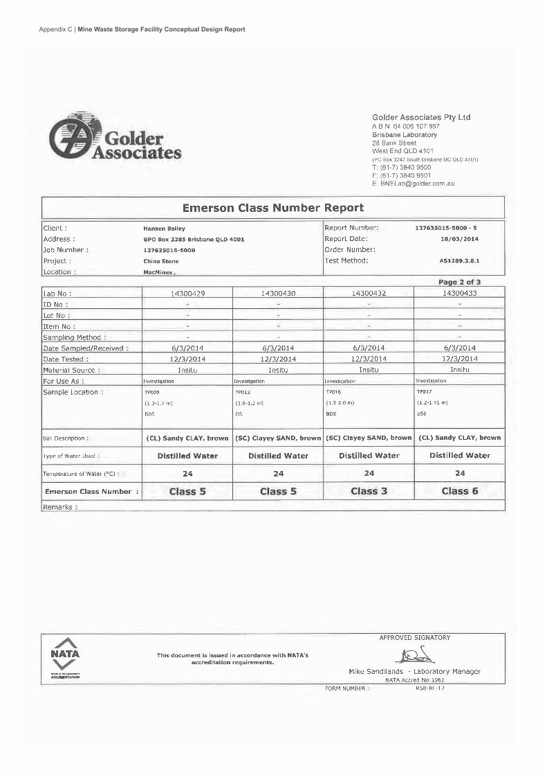
Appendix C | Mine Waste Storage Facility Conceptual Design Report

Appendix C | Mine Waste Storage Facility Conceptual Design Report
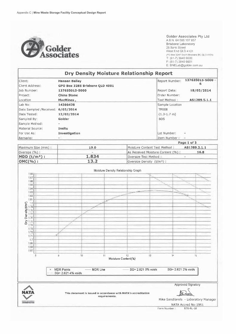
Appendix C | Mine Waste Storage Facility Conceptual Design Report

Appendix C | Mine Waste Storage Facility Conceptual Design Report

Appendix C | Mine Waste Storage Facility Conceptual Design Report

Appendix C | Mine Waste Storage Facility Conceptual Design Report

Appendix C | Mine Waste Storage Facility Conceptual Design Report

Appendix C | Mine Waste Storage Facility Conceptual Design Report

Appendix C | Mine Waste Storage Facility Conceptual Design Report

Appendix C | Mine Waste Storage Facility Conceptual Design Report

PROJECT CHINA STONE EIS - REJECTS MANAGEMENT
November 2014 Report No. 137635015-005-R-Rev0
APPENDIX C Results of Slope Stability Analysis
DAT
E
DAT
E
FIG
UR
E N
o
CLI
ENT
DR
AW
N
CH
EC
KED
SCAL
E
TITL
E
PRO
JEC
T N
o
PRO
JEC
T
NTS
Chi
na S
tone
Pro
ject
- M
ine
Was
te S
tora
ge
A4
REV
No
MA
CM
INE
S A
US
TAS
IA
013
7635
015-
005
CM
July
201
4
ABN
ov 2
014
C-1
Slo
pe S
tabi
lity
Ana
lysi
s C
ase
1: T
SF
perm
anen
t slo
pe-li
ner
Appendix C | Mine Waste Storage Facility Conceptual Design Report

DATE
DATE
FIGURE No
CLIENT
DRAWN
CHECKED
SCALE
TITLE
PROJECT No
PROJECT
NTS
China Stone Project - Mine Waste Storage
A4REV No
MACMINES AUSTASIA
0137635015-005
CM July 2014
AB Nov 2014
C-1
Slope Stability Analysis Case 1: TSF permanent slope-liner
Appendix C
| Mine W
aste Storage Facility Conceptual D
esign Report

DATE
DATE
FIGURE No
CLIENT
DRAWN
CHECKED
SCALE
TITLE
PROJECT No
PROJECT
NTS
China Stone Project - Mine Waste Storage
A4REV No
MACMINES AUSTASIA
0137635015-005
CM July 2014
AB Nov 2014Slope Stability Analysis
Case 2: TSF permanent slope-No liner
C-2
DATE
DATE
FIGURE No
CLIENT
DRAWN
CHECKED
SCALE
TITLE
PROJECT No
PROJECT
NTS
China Stone Project - Mine Waste Storage
A4REV No
MACMINES AUSTASIA
0137635015-005
CM July 2014
AB Nov 2014Slope Stability Analysis
Case 3: TSF Operational slope- liner
C-3
Appendix C
| Mine W
aste Storage Facility Conceptual D
esign Report

DATE
DATE
FIGURE No
CLIENT
DRAWN
CHECKED
SCALE
TITLE
PROJECT No
PROJECT
NTS
China Stone Project - Mine Waste Storage
A4REV No
MACMINES AUSTASIA
0137635015-005
CM July 2014
AB Nov 2014Slope Stability Analysis
Case 4: TSF Operational slope- No Liner
C-4
DATE
DATE
FIGURE No
CLIENT
DRAWN
CHECKED
SCALE
TITLE
PROJECT No
PROJECT
NTS
China Stone Project - Mine Waste Storage
A4REV No
MACMINES AUSTASIA
0137635015-005
CM July 2014
AB Nov 2014Slope Stability Analysis
Case 5: Power station waste storage facility
C-5
Appendix C
| Mine W
aste Storage Facility Conceptual D
esign Report

DATE
DATE
FIGURE No
CLIENT
DRAWN
CHECKED
SCALE
TITLE
PROJECT No
PROJECT
NTS
China Stone Project - Mine Waste Storage
A4REV No
MACMINES AUSTASIA
0137635015-005
CM July 2014
AB Nov 2014Slope Stability Analysis
Case 5: Power station waste storage facility
C-5
Appendix C
| Mine W
aste Storage Facility Conceptual D
esign Report

PROJECT CHINA STONE EIS - REJECTS MANAGEMENT
November 2014 Report No. 137635015-005-R-Rev0
APPENDIX D Limitations
Appendix C | Mine Waste Storage Facility Conceptual Design Report

LIMITATIONS
This Document has been provided by Golder Associates Pty Ltd (“Golder”) subject to the following limitations:
This Document has been prepared for the particular purpose outlined in Golder’s proposal and no responsibility is accepted for the use of this Document, in whole or in part, in other contexts or for any other purpose.
The scope and the period of Golder’s Services are as described in Golder’s proposal, and are subject to restrictions and limitations. Golder did not perform a complete assessment of all possible conditions or circumstances that may exist at the site referenced in the Document. If a service is not expressly indicated, do not assume it has been provided. If a matter is not addressed, do not assume that any determination has been made by Golder in regards to it.
Conditions may exist which were undetectable given the limited nature of the enquiry Golder was retained to undertake with respect to the site. Variations in conditions may occur between investigatory locations, and there may be special conditions pertaining to the site which have not been revealed by the investigation and which have not therefore been taken into account in the Document. Accordingly, additional studies and actions may be required.
In addition, it is recognised that the passage of time affects the information and assessment provided in this Document. Golder’s opinions are based upon information that existed at the time of the production of the Document. It is understood that the Services provided allowed Golder to form no more than an opinion of the actual conditions of the site at the time the site was visited and cannot be used to assess the effect of any subsequent changes in the quality of the site, or its surroundings, or any laws or regulations.
Any assessments made in this Document are based on the conditions indicated from published sources and the investigation described. No warranty is included, either express or implied, that the actual conditions will conform exactly to the assessments contained in this Document.
Where data supplied by the client or other external sources, including previous site investigation data, have been used, it has been assumed that the information is correct unless otherwise stated. No responsibility is accepted by Golder for incomplete or inaccurate data supplied by others.
Golder may have retained subconsultants affiliated with Golder to provide Services for the benefit of Golder. To the maximum extent allowed by law, the Client acknowledges and agrees it will not have any direct legal recourse to, and waives any claim, demand, or cause of action against, Golder’s affiliated companies, and their employees, officers and directors.
This Document is provided for sole use by the Client and is confidential to it and its professional advisers. No responsibility whatsoever for the contents of this Document will be accepted to any person other than the Client. Any use which a third party makes of this Document, or any reliance on or decisions to be made based on it, is the responsibility of such third parties. Golder accepts no responsibility for damages, if any, suffered by any third party as a result of decisions made or actions based on this Document.
GOLDER ASSOCIATES PTY LTD GAP Form No. LEG 04 RL 1
Appendix C | Mine Waste Storage Facility Conceptual Design Report

Golder Associates Pty Ltd 147 Coronation Drive Milton, Queensland 4064 AustraliaT: +61 7 3721 5400
Appendix C | Mine Waste Storage Facility Conceptual Design Report


