Peak USB to CANInterfaces
distributes the Peak System range of CAN
and CAN FD Interfaces, Adapters, I/O Modules, Data
Acquisition Systems and Supporting Software.
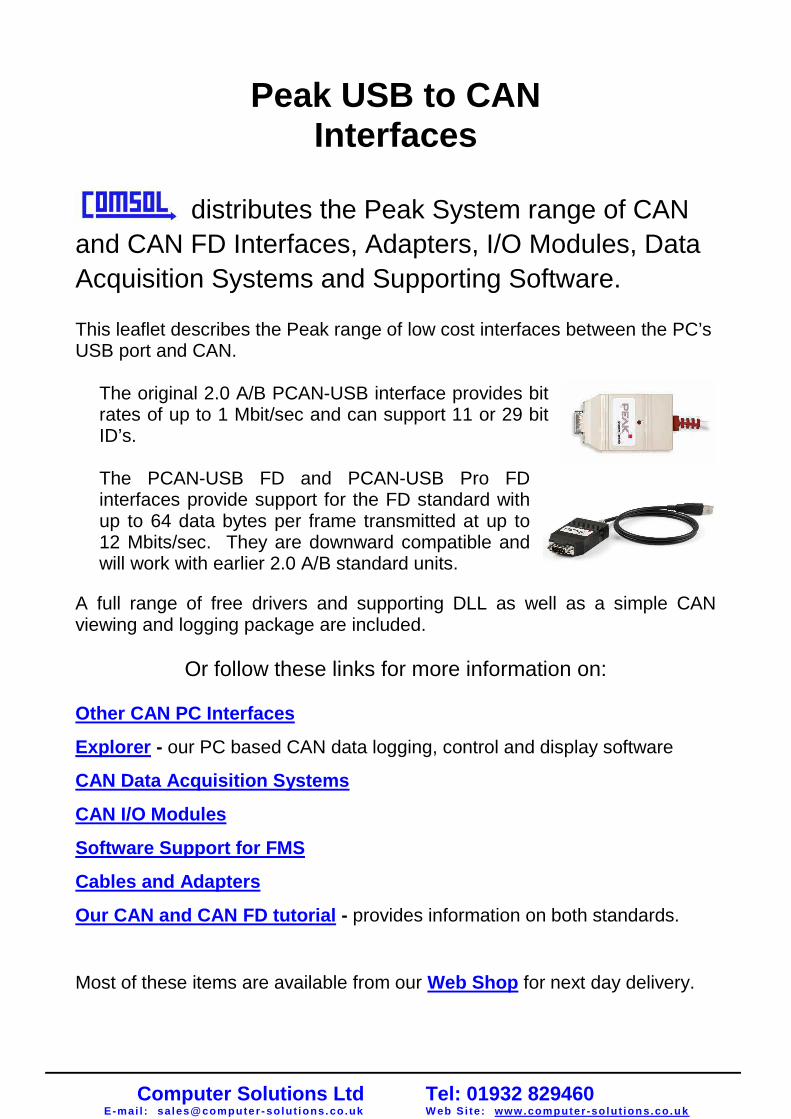
This leaflet describes the Peak range of low cost interfaces between the PC’sUSB port and CAN.
The original 2.0 A/B PCAN-USB interface provides bitrates of up to 1 Mbit/sec and can support 11 or 29 bitID’s.
The PCAN-USB FD and PCAN-USB Pro FDinterfaces provide support for the FD standard withup to 64 data bytes per frame transmitted at up to12 Mbits/sec. They are downward compatible andwill work with earlier 2.0 A/B standard units.
A full range of free drivers and supporting DLL as well as a simple CANviewing and logging package are included.
Or follow these links for more information on:
Other CAN PC Interfaces
Explorer - our PC based CAN data logging, control and display software
CAN Data Acquisition Systems
CAN I/O Modules
Software Support for FMS
Cables and Adapters
Our CAN and CAN FD tutorial - provides information on both standards.
Most of these items are available from our Web Shop for next day delivery.
Computer Solutions LtdE-mai l : sales@computer - solut ions. co.uk
Tel: 01932 829460W eb Si te: www.computer -solut ions.co.uk

8
PCAN-USBUSB to CAN Interface
Hardware >> CAN Interfaces
Specifications
Adapter for USB connection
(USB 1.1, compatible with USB 2.0)
USB voltage supply
Bit rates up to 1 Mbit/s
Time stamp resolution approx. 42 µs
Compliant with CAN specifications
2.0A (11-bit ID) and 2.0B (29-bit ID)
CAN bus connection via D-Sub,
9-pin (in accordance with CiA® 102)
NXP SJA1000 CAN controller,
16 MHz clock frequency
NXP PCA82C251 CAN transceiver
5-Volts supply to the CAN connection can be
connected through a solder jumper, e.g. for
external bus converter
Extended operating temperature range
from -40 to 85 °C (-40 to 185 °F)
Optionally available:
Galvanic isolation on the CAN connection
up to 500 V
www.peak-system.com Products 2011 / 2012
Designation Art. No.
PCAN-USB IPEH-002021
PCAN-USB opto-decoupled IPEH-002022
Scope of supply
PCAN-USB in plastic casing
Device drivers for
Windows 7/Vista/XP/Linux (32/64-bit)
Device driver for Windows CE 6.x
(x86 and ARMv4 processor support)
PCAN-View CAN monitor for Windows
(details on page 51)
PCAN-Basic programming interface consisting
of an interface DLL, examples, and header files
for all common programming languages
(details on page 46)
Manual in PDF format
Ordering information
D-Sub Pin Pin assignment1 Not connected / optional +5V2 CAN-L3 GND4 Not connected5 Not connected6 GND7 CAN-H8 Not connected9 Not connected / optional +5V
1
6
5
9
The PCAN-USB adapter enables simple connection
to CAN networks. Its compact plastic casing makes it
suitable for mobile applications.
The opto-decoupled version guarantees galvanic
isolation of up to 500 Volts between the PC and the
CAN sides.
The package is also supplied with the CAN monitor
PCAN-View for Windows and the programming
interface PCAN-Basic.
Computer Solutions LtdE-mai l : sales@computer - solut ions. co.uk
Tel: 01932 829460W eb Si te: www.computer -solut ions.co.uk
Designation Part No.
PCAN-USB FD IPEH-004022
Scope of supply
PCAN-USB FD in plastic casing
Device drivers for Windows 8.1, 7, Vista and Linux
(32/64-bit)
PCAN-View CAN monitor for Windows
(details on page 85)
PCAN-Basic programming interface consisting of
an interface DLL, examples, and header files for
all common programming languages (details on
page 76)
Manual in PDF format
Ordering information
D-Sub Pin Pin assignment1 Not connected / optional +5V2 CAN-L3 GND4 Not connected5 Not connected6 GND7 CAN-H8 Not connected9 Not connected
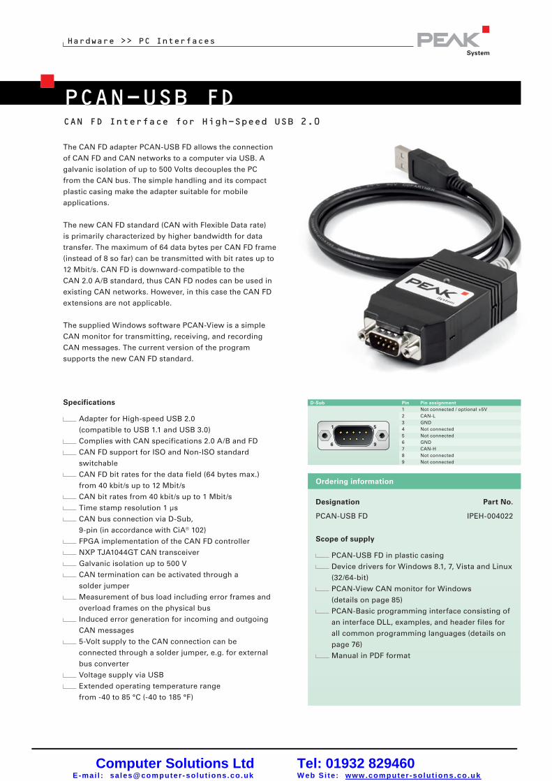
PCAN-USB FD
Hardware >> PC Interfaces
CAN FD Interface for High-Speed USB 2.0
www.peak-system.com Products 2015
Specifications
Adapter for High-speed USB 2.0
(compatible to USB 1.1 and USB 3.0)
Complies with CAN specifications 2.0 A/B and FD
CAN FD support for ISO and Non-ISO standard
switchable
CAN FD bit rates for the data field (64 bytes max.)
from 40 kbit/s up to 12 Mbit/s
CAN bit rates from 40 kbit/s up to 1 Mbit/s
Time stamp resolution 1 µs
CAN bus connection via D-Sub,
9-pin (in accordance with CiA® 102)
FPGA implementation of the CAN FD controller
NXP TJA1044GT CAN transceiver
Galvanic isolation up to 500 V
CAN termination can be activated through a
solder jumper
Measurement of bus load including error frames and
overload frames on the physical bus
Induced error generation for incoming and outgoing
CAN messages
5-Volt supply to the CAN connection can be
connected through a solder jumper, e.g. for external
bus converter
Voltage supply via USB
Extended operating temperature range
from -40 to 85 °C (-40 to 185 °F)
The CAN FD adapter PCAN-USB FD allows the connection
of CAN FD and CAN networks to a computer via USB. A
galvanic isolation of up to 500 Volts decouples the PC
from the CAN bus. The simple handling and its compact
plastic casing make the adapter suitable for mobile
applications.
The new CAN FD standard (CAN with Flexible Data rate)
is primarily characterized by higher bandwidth for data
transfer. The maximum of 64 data bytes per CAN FD frame
(instead of 8 so far) can be transmitted with bit rates up to
12 Mbit/s. CAN FD is downward-compatible to the
CAN 2.0 A/B standard, thus CAN FD nodes can be used in
existing CAN networks. However, in this case the CAN FD
extensions are not applicable.
The supplied Windows software PCAN-View is a simple
CAN monitor for transmitting, receiving, and recording
CAN messages. The current version of the program
supports the new CAN FD standard.
11
Computer Solutions LtdE-mai l : sales@computer - solut ions. co.uk
Tel: 01932 829460W eb Si te: www.computer -solut ions.co.uk

PCAN-USB Pro FD
Hardware >> PC Interfaces
CAN FD and LIN Interface for High-Speed USB 2.0
www.peak-system.com Products 2015
The monitor application PLIN-View Pro as well as the PLIN
programming interface are also included in the scope of
supply.
Specifications
Adapter for High-speed USB 2.0
(compatible to USB 1.1 and USB 3.0)
Transmitting and receiving of CAN FD and LIN
messages using 2 D-Sub connections (both with pin
assignment for the CAN FD and LIN bus)
Time stamp resolution 1 µs
5-Volt supply at the D-Sub connector can be activated
through a solder jumper, e.g. for external bus
converter
Voltage supply via USB
Extended operating temperature range
from -40 to 85 °C (-40 to 185 °F)
CAN operation properties:
Complies with CAN specifications 2.0 A/B and FD
CAN FD support for ISO and Non-ISO standard
switchable
CAN FD bit rates for the data field (64 bytes max.)
from 40 kbit/s up to 12 Mbit/s
CAN bit rates from 40 kbit/s up to 1 Mbit/s
The PCAN-USB Pro FD adapter enables the connection
of CAN FD and LIN networks to a computer via USB.
Two field busses can be connected at the same time, up
to four with appropriate adapter cables (2 x CAN FD, 2 x
LIN). Each CAN FD channel is separately isolated against
USB and LIN with a maximum of 500 Volts. Its robust
aluminum casing makes the PCAN-USB Pro FD adapter
suitable for mobile applications.
The new CAN FD standard (CAN with Flexible Data rate)
is primarily characterized by higher bandwidth for data
transfer. The maximum of 64 data bytes per CAN FD frame
(instead of 8 so far) can be transmitted with bit rates up to
12 Mbit/s. CAN FD is downward-compatible to the
CAN 2.0 A/B standard, thus CAN FD nodes can be used in
existing CAN networks. However, in this case the CAN FD
extensions are not applicable.
The supplied Windows software PCAN-View is a simple
CAN monitor for transmitting, receiving, and recording
CAN messages. The current version of the program
supports the new CAN FD standard.
12
Computer Solutions LtdE-mai l : sales@computer - solut ions. co.uk
Tel: 01932 829460W eb Si te: www.computer -solut ions.co.uk

Hardware >> PC Interfaces
www.peak-system.com Products 2015
Designation Part No.
PCAN-USB Pro FD IPEH-004061
Scope of supply
PCAN-USB Pro FD in aluminum casing
CAN FD interface drivers for Windows 8.1, 7, Vista
and Linux (32/64 bit)
LIN interface drivers for Windows 8.1, 7, Vista
(32/64 bit)
PCAN-View CAN monitor for Windows
(details on page 85)
PLIN-View Pro LIN monitor for Windows
(details on page 86)
PCAN-Basic programming interface consisting of
an interface DLL, examples, and header files for
all common programming languages
(details on page 76)
PLIN-API programming interface consisting of an
interface DLL, an example, and header files for all
common programming languages
Manual in PDF format
Please note: The PCAN-USB Pro FD can be used
alternatively for the PCAN-USB Pro, because this CAN
interface is no longer manufactured!
The PCAN-USB Pro FD behaves identically concerning
the CAN and LIN functionality.
Ordering information
D-Sub Pin Pin assignment1 Not connected / optional +5V2 CAN-L3 CAN-GND4 LIN5 LIN-GND6 LIN-GND7 CAN-H8 Not connected9 VBAT
FPGA implementation of the CAN FD controller
NXP TJA1044GT CAN transceiver
Each CAN FD channel is separately opto-decoupled
against USB and LIN up to 500 V
CAN termination can be activated through a
solder jumper
Measurement of bus load including error frames and
overload frames on the physical bus
Induced error generation for incoming and outgoing
CAN messages
LIN operation properties:
Bit rates from 1 kbit/s up to 20 kbit/s
TJA1021/20 LIN transceiver
Both LIN channels (common ground) are opto-
decoupled against USB and CAN FD
Can be used as a LIN master or slave
(1 ms master task resolution)
Automatic bit rate, frame length, and checksum type
recognition
Autonomous scheduler with support for
unconditional, event, and sporadic frames
Hardware can work through a schedule table
(up to 8 schedule tables can be configured with a total
of 256 slots)
13
Computer Solutions LtdE-mai l : sales@computer - solut ions. co.uk
Tel: 01932 829460W eb Si te: www.computer -solut ions.co.uk

Using CAN
PEAK CAN ControllersThe Peak range of CAN interfaces provides simple and cost effective connections between PCsand CAN-networks and includes routers, extenders and adapters to the many CAN variants.
PCAN interfaces support both 11 bit ID and 29 bit ID CAN specifications with a maximum speedof 1Mbaud. They use the SJA1000 CAN-controller and the 82C251 driver. The CAN-bus connection isvia a 9-pin SUB-D plug, whose pin assignments conform to the CiA recommendation. No termination isincluded in the interfaces. Optoisolated versions are available if required and most interfaces can besupplied with one or two ports.
Drivers and supporting DLL’s are included to allowoperation under XP, Vista, Windows 7 and Linux in32 and 64* bit modes. CE6.x support* for ARMand x86 is also available. (* most interfaces).Language support is provided for C++, C#,C++/CLR, Delphi, VB.NET, Java and Python 2.6.
A Windows package PCAN-View is included withall interfaces to allow the user to view messages onthe CAN bus. All data is displayed in Hex andmessages are timed and counted. A trace bufferallows messages to be recorded and saved to disk.Errors such as over-run and baud rate problemsare reported. Messages can be user created and
then sent as one-shot, repeating periodically or in response to a remote request (RTR).
Industrial I/O ModulesThese Industrial I/O modules are available in a number of usefulconfigurations including signal conditioning and termination in an industrialcase. Up to 8 10 bit analogue inputs, 4 PWM/frequency outputs (to 20KHz)and 8 digital ins and outs are available. At 51 x 60 x 20mm, they are suitablefor a wide variety of applications. The electrical connections provide snap-intermination; with a screw connection as an option. A windows package isprovided so that the user can set message ID and data layouts andconversion constants as well as setting report rates or reporting on change.
CAN Open firmware is also available if required.
USB
PC/104
PCMCIA PARALLEL PORT
ISA
PCI
Computer Solutions LtdE-mai l : sales@computer - solut ions. co.uk
Tel: 01932 829460W eb Si te: www.computer -solut ions.co.uk
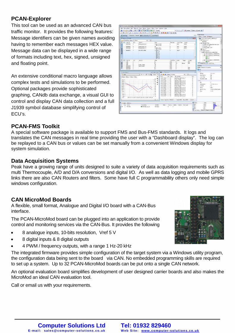
PCAN-ExplorerThis tool can be used as an advanced CAN bus
traffic monitor. It provides the following features:
Message identifiers can be given names avoiding
having to remember each messages HEX value.
Message data can be displayed in a wide range
of formats including text, hex, signed, unsigned
and floating point.
An extensive conditional macro language allows
complex tests and simulations to be performed.
Optional packages provide sophisticated
graphing, CANdb data exchange, a visual GUI to
control and display CAN data collection and a full
J1939 symbol database simplifying control of
ECU’s.
PCAN-FMS ToolkitA special software package is available to support FMS and Bus-FMS standards. It logs andtranslates the CAN messages in real time providing the user with a “Dashboard display”. The log canbe replayed to a CAN bus or values can be set manually from a convenient Windows display forsystem simulation.
Data Acquisition SystemsPeak have a growing range of units designed to suite a variety of data acquisition requirements such asmulti Thermocouple, A/D and D/A conversions and digital I/O. As well as data logging and mobile GPRSlinks there are also CAN Routers and filters. Some have full C programmability others only need simplewindows configuration.
CAN MicroMod BoardsA flexible, small format, Analogue and Digital I/O board with a CAN-Businterface.
The PCAN-MicroMod board can be plugged into an application to providecontrol and monitoring services via the CAN-Bus. It provides the following
8 analogue inputs, 10-bits resolution, Vref 5 V
8 digital inputs & 8 digital outputs
4 PWM / frequency outputs, with a range 1 Hz-20 kHz
The integrated firmware provides simple configuration of the target system via a Windows utility program,the configuration data being sent to the board via CAN. No embedded programming skills are requiredto set up a system. Up to 32 PCAN-MicroMod boards can be put onto a single CAN network.
An optional evaluation board simplifies development of user designed carrier boards and also makes theMicroMod an ideal CAN evaluation tool.
Call or email us with your requirements.
Computer Solutions LtdE-mai l : sales@computer - solut ions. co.uk
Tel: 01932 829460W eb Si te: www.computer -solut ions.co.uk

59
PCAN-Explorer 5 Comprehensive CAN Monitor for Windows
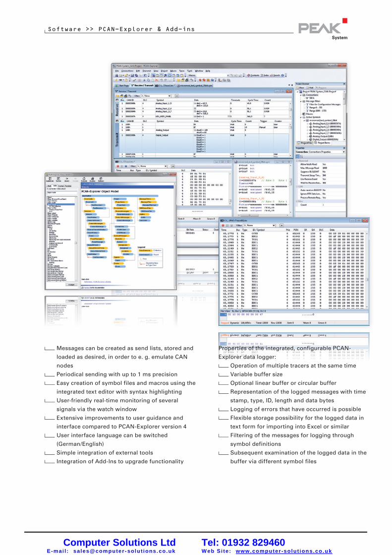
Software >> PCAN-Explorer & Add-ins
www.peak-system.com Products 2011 / 2012
PCAN-Explorer is a universal tool for monitoring data
traffic on a CAN network. For easy and clear allocation
of the individual messages, these can be identified as
so-called symbols. The integrated VBScript support
allows the creation of macros to automate complex
tasks. The integrated data logger means that the data
traffic of a bus can be recorded, analyzed, and stored.
PCAN-Explorer is designed as automation server and
can therefore be remote controlled through scripts.
Features
All files and elements can be managed and saved
in projects
Project components such as CAN connections,
symbol files and macros are clearly displayed and
laid out in the project browser
The new start page allows fast access to the most
recently opened projects or files
Simultaneous connections with multiple networks/
CAN interfaces of the same hardware type
Connection window with an overview of all
connections, complete with status, error counters,
bus load, etc.
All parameters of all elements in the user interface
can be examined using a property window and
edited if necessary.
Multiple flexible filters can be configured and, for
example, assigned to the transmit/receive window
or the various different tracers
Tabs to switch between the different Windows
Flexible arrangement of the user interface using
the dockable windows
User-defined column display and arrangement in
transmit/receive window
J1939 support with the relevant add-in
Display of received messages showing the ID,
length, data bytes, number of messages received
and receiving interval
Simultaneous hexadecimal and symbolic
representation of the details
Display of remote frames, status reports of the
CAN controller and, as option, CAN-bus error
frames also
Logging of time-outs
Sending of messages at fixed intervals of time,
manually or as reply to remote frames
Computer Solutions LtdE-mai l : sales@computer - solut ions. co.uk
Tel: 01932 829460W eb Si te: www.computer -solut ions.co.uk
60
Software >> PCAN-Explorer & Add-ins
www.peak-system.com Products 2011 / 2012
Messages can be created as send lists, stored and
loaded as desired, in order to e. g. emulate CAN
nodes
Periodical sending with up to 1 ms precision
Easy creation of symbol files and macros using the
integrated text editor with syntax highlighting
User-friendly real-time monitoring of several
signals via the watch window
Extensive improvements to user guidance and
interface compared to PCAN-Explorer version 4
User interface language can be switched
(German/English)
Simple integration of external tools
Integration of Add-Ins to upgrade functionality
Properties of the integrated, configurable PCAN-
Explorer data logger:
Operation of multiple tracers at the same time
Variable buffer size
Optional linear buffer or circular buffer
Representation of the logged messages with time
stamp, type, ID, length and data bytes
Logging of errors that have occurred is possible
Flexible storage possibility for the logged data in
text form for importing into Excel or similar
Filtering of the messages for logging through
symbol definitions
Subsequent examination of the logged data in the
buffer via different symbol files
Computer Solutions LtdE-mai l : sales@computer - solut ions. co.uk
Tel: 01932 829460W eb Si te: www.computer -solut ions.co.uk

61
Function upgrade of the PCAN-Explorer with the
integrated VBScript language:
Creation of macros in VBScript with the integrated
text editor
Access with macros and scripts to almost all
program elements via the PCAN-Explorer object
model
Ideal for creating test tools to implement or
develop CAN systems
Examples: sending of e-mails when a temperature
is exceeded, starting of a test tool when a
particular message is received, opening of an
Excel sheet when an event occurs and saving of
data in the individual cells
Assignment of function keys with individual send
messages or macros
VBS scripts run in the background even without
the PCAN-Explorer interface
www.peak-system.com Products 2011 / 2012
Software >> PCAN-Explorer & Add-ins
Designation Art. No.
PCAN-Explorer 5 IPES-005028
Scope of supply
PCAN-Explorer installation CD including
PCAN-Explorer Line Writer Add-in
PCAN Symbol Editor for Windows
(details on page 62)
Documentation in HTML help format
System requirements
Windows 7/Vista/XP (32/64-bit)
At least 512 MB RAM and 1 GHz CPU
Ordering information
Computer Solutions LtdE-mai l : sales@computer - solut ions. co.uk
Tel: 01932 829460W eb Si te: www.computer -solut ions.co.uk

63
Software >> PCAN-Explorer & Add-ins
Optional Function Upgrades for PCAN-Explorer
PCAN-Explorer Add-ins
Designation Art. No.
J1939 Add-in IPES-005089
Scope of supply
J1939 Add-in software
Documentation in HTML help format
System requirements
PCAN-Explorer 5
Windows 7/Vista/XP (32/64-bit)
At least 512 MB RAM and 1 GHz CPU
Ordering informationJ1939 Add-in
The SAE J1939 network protocol describes
communication on a CAN bus in utility vehicles for
the transmission of diagnostics data and control
information. It contains a complete network definition
using 29-bit CAN-IDs (CAN 2.0B Extended Frame).
The J1939 add-in for PCAN-Explorer 5 supports all
definitions established by the standard’s parameter
groups and provides a simple means of accessing the
parameters. A complete database of all the definitions
and the parameters contained is also supplied.
Features
Support for all functions of the SAE J1939 network
protocol
CAN messages can be sent in broadcast form or
targeted to individual control units (ECUs)
Addressing of up to 254 ECUs
Supports multi-packet messages
www.peak-system.com Products 2011 / 2012 Computer Solutions LtdE-mai l : sales@computer - solut ions. co.uk
Tel: 01932 829460W eb Si te: www.computer -solut ions.co.uk

64
PCAN-Explorer Add-insOptional Function Upgrades for PCAN-Explorer
Software >> PCAN-Explorer & Add-ins
Designation Art. No.
Plotter Add-in 2 IPES-005087
Scope of supply
PCAN-Plotter Add-in software
System requirements
PCAN-Explorer 5
Windows 7/Vista/XP (32/64-bit)
At least 512 MB RAM and 1 GHz CPU
Ordering information
Plotter Add-in 2
The plotter allows the graphical representation of CAN
data using any number of channels.
Features
Real-time display
Unlimited number of channels
Unlimited number of Y-axes
X-axis and Y-axes can be zoomed and scrolled
quite freely, even during recording
Labelling of time axis with absolute or relative
time stamps
Facility for automatic adaptation of axes to plots
Reversible Y-axes
Logarithmic scales
Cursor display for plot measurement
Export to EMF-, PNG-, BMP-, JPEG graphical
formats
Data import from the PCAN-Explorer Tracer
www.peak-system.com Products 2011 / 2012
Representation of limiting values and value ranges
Comprehensive formatting options for
representing the curves, axes and the plotter
layout
Computer Solutions LtdE-mai l : sales@computer - solut ions. co.uk
Tel: 01932 829460W eb Si te: www.computer -solut ions.co.uk

65
PCAN-Explorer Add-insOptional Function Upgrades for PCAN-Explorer
Software >> PCAN-Explorer & Add-ins
Designation Art. No.
CANdb Import Add-in 3 IPES-005086
Scope of supply
CANdb Import Add-in software
Documentation in HTML help format
System requirements
PCAN-Explorer 5
Windows 7/Vista/XP (32/64-bit)
At least 512 MB RAM and 1 GHz CPU
Ordering information
www.peak-system.com Products 2011 / 2012
CANdb Import Add-in 3
The CANdb format is a common data description
format for CAN bus information in the car industry.
CANdb Import allows the import of CANdb files. This
is a useful function for all those who do not want to
manually transcribe their database into the
PCAN-Explorer symbol file format.
Features
Opening of CANdb files (.dbc)
Selecting of the messages for importing in a
CANdb file
Saves data using the project administration
function in PCAN-Explorer
Storing in the PCAN-Explorer symbol file format
Computer Solutions LtdE-mai l : sales@computer - solut ions. co.uk
Tel: 01932 829460W eb Si te: www.computer -solut ions.co.uk

66
PCAN-Explorer Add-insOptional Function Upgrades for PCAN-Explorer
Software >> PCAN-Explorer & Add-ins
www.peak-system.com Products 2011 / 2012
Instruments Panel Add-in 3
The Instruments Panel Add-in allows the graphical
representation of digital and analog signals using
different display instruments. The integrated input
options and controllers mean that signals can also be
produced on the CAN bus, allowing easy simulation of
complex CAN applications.
Free positioning of the instruments using
drag & drop, or numerical inputs for spot-on
positioning
Loading and storing of complete panel
configurations
Features
Representation of analog and digital signals from
received CAN messages using different display
instruments
In addition to potentiometers, switches, and
sliding controllers input fields can be used to
generate CAN messages
Selection and configuration of multiple elements
at the same time
Extensive configuration of the properties of one or
more elements using the new property window
The new Instruments Panel object model enables
complete automation using COM and scripts
Representation of different scenes on the same
panel during running time
Signal-dependent display of image lists and
scenes
Designation Art. No.
Instruments Panel Add-in 3 IPES-005088
Scope of supply
Instruments Panel Add-in software
Documentation in HTML help format
System requirements
PCAN-Explorer 5
Windows 7/Vista/XP (32/64-bit)
At least 512 MB RAM and 1 GHz CPU
Ordering information
Computer Solutions LtdE-mai l : sales@computer - solut ions. co.uk
Tel: 01932 829460W eb Si te: www.computer -solut ions.co.uk
58
PCAN-TraceComprehensive Data Logger for CAN Messages
Software >> Application Software
Designation Art. No.
PCAN-Trace IPES-002027
Scope of supply
PCAN-Trace installation CD
(in English)
Documentation in HTML help format
System requirements
Windows 7/Vista/XP (32-bit)
At least 512 MB RAM and 1 GHz CPU
Ordering information
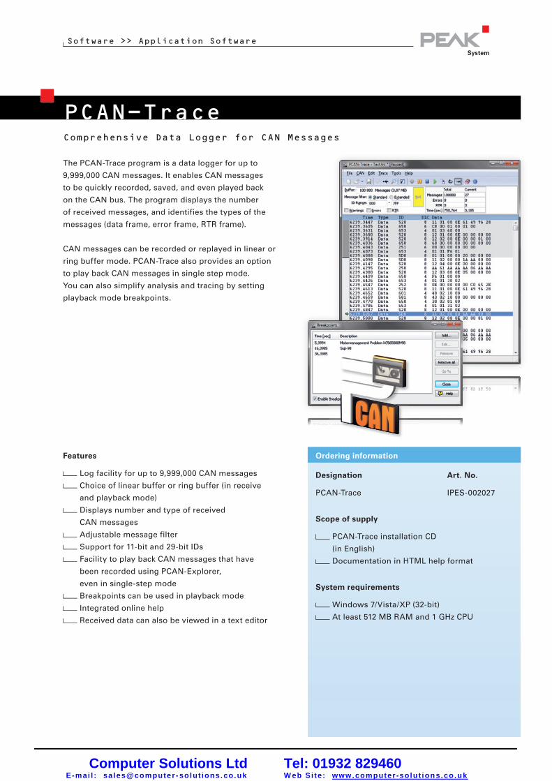
The PCAN-Trace program is a data logger for up to
9,999,000 CAN messages. It enables CAN messages
to be quickly recorded, saved, and even played back
on the CAN bus. The program displays the number
of received messages, and identifies the types of the
messages (data frame, error frame, RTR frame).
CAN messages can be recorded or replayed in linear or
ring buffer mode. PCAN-Trace also provides an option
to play back CAN messages in single step mode.
You can also simplify analysis and tracing by setting
playback mode breakpoints.
www.peak-system.com Products 2011 / 2012
Features
Log facility for up to 9,999,000 CAN messages
Choice of linear buffer or ring buffer (in receive
and playback mode)
Displays number and type of received
CAN messages
Adjustable message filter
Support for 11-bit and 29-bit IDs
Facility to play back CAN messages that have
been recorded using PCAN-Explorer,
even in single-step mode
Breakpoints can be used in playback mode
Integrated online help
Received data can also be viewed in a text editor
Computer Solutions LtdE-mai l : sales@computer - solut ions. co.uk
Tel: 01932 829460W eb Si te: www.computer -solut ions.co.uk


