
10/22/2013
Movement to the full
Digital Substation
CIGRE
Ravindranauth Ramlachan

© ALSTOM 2013. All rights reserved. Information contained in this document is indicative only. No representation or warranty is given or should be relied on that it is complete or correct or will apply to any particular project. This will depend on the technical and commercial circumstances. It is provided without liability and is subject to change without notice. Reproduction, use or disclosure to third parties, without express written authority, is strictly prohibited.
Presentation title - 24/10/2013 – P 2
• Safety issues – equipment isolation, touch and step potentials, EMC
• Copper – raw material cost has increased 400% in 10 years
• Material cost – cubicle wiring and test costs, labour cost per wire end
termination
• Schematic design - verification cost, excessive on-site work content
• Civil work costs – trays, troughing, cable access/egress…
• Maintainability cost
Why Digital - Wiring, wiring, wiring…….

© ALSTOM 2013. All rights reserved. Information contained in this document is indicative only. No representation or warranty is given or should be relied on that it is complete or correct or will apply to any particular project. This will depend on the technical and commercial circumstances. It is provided without liability and is subject to change without notice. Reproduction, use or disclosure to third parties, without express written authority, is strictly prohibited.
Presentation title - 24/10/2013 – P 3
What is a Digital Substation?
Digital substations are those which have embedded processing
intelligence in order to implement part of their operational duties,
and as such typically exceed the capability of their analogue
predecessors. The intelligence adds:
• Ease of use
• Asset management
• Modularity
• Vendor interoperability
• Real time awareness
Realized by digitizing the data related to the primary process at the point where it is measured

© ALSTOM 2013. All rights reserved. Information contained in this document is indicative only. No representation or warranty is given or should be relied on that it is complete or correct or will apply to any particular project. This will depend on the technical and commercial circumstances. It is provided without liability and is subject to change without notice. Reproduction, use or disclosure to third parties, without express written authority, is strictly prohibited.
Presentation title - 24/10/2013 – P 4
The Digital Substation – Architect Levels
CIT & NCIT CTs and VTs
Station Control
Protection and
Control
Primary
Equipment
Process

© ALSTOM 2013. All rights reserved. Information contained in this document is indicative only. No representation or warranty is given or should be relied on that it is complete or correct or will apply to any particular project. This will depend on the technical and commercial circumstances. It is provided without liability and is subject to change without notice. Reproduction, use or disclosure to third parties, without express written authority, is strictly prohibited.
Presentation title - 24/10/2013 – P 5
Key Drivers
Improved Safety -Eliminate open circuit CTs Asset Optimisation -Intelligent monitoring of equipment Reduced Maintenance Cost -Condition-based maintenance Optimisation of New Investments Increased Reliability and Availability extensive self-diagnosis capability, redundancy
Why install a digital substation? “Not only does it optimise overall lifecycle costs, it is easier to use. Asset managers now have a vital tool that, with less
wiring and fewer commissioning tests, accommodates preventive maintenance and can extend transformer and
switchgear lifetime. Digital substations are modular, so they can be tailored to system needs and open to third-party
devices. It is easy to retrofit protection and control schemes with minimal outage constraints. Ultimately, operators
manage a smarter grid, with better, more complete real-time situational awareness, making the system more available and
secure.”

© ALSTOM 2013. All rights reserved. Information contained in this document is indicative only. No representation or warranty is given or should be relied on that it is complete or correct or will apply to any particular project. This will depend on the technical and commercial circumstances. It is provided without liability and is subject to change without notice. Reproduction, use or disclosure to third parties, without express written authority, is strictly prohibited.
Presentation title - 24/10/2013 – P 6
Key Drivers
Standardisation and Interoperability -Multi Vendor Ease of Refurbishment -Refurbish with minimum primary outage Improved communication capability -Data available to all levels Environmental Responsibility -Wiring is reduced by typically 80%.
Why install a digital substation? “Not only does it optimise overall lifecycle costs, it is easier to use. Asset managers now have a vital tool that, with less
wiring and fewer commissioning tests, accommodates preventive maintenance and can extend transformer and
switchgear lifetime. Digital substations are modular, so they can be tailored to system needs and open to third-party
devices. It is easy to retrofit protection and control schemes with minimal outage constraints. Ultimately, operators
manage a smarter grid, with better, more complete real-time situational awareness, making the system more available and
secure.”

© ALSTOM 2013. All rights reserved. Information contained in this document is indicative only. No representation or warranty is given or should be relied on that it is complete or correct or will apply to any particular project. This will depend on the technical and commercial circumstances. It is provided without liability and is subject to change without notice. Reproduction, use or disclosure to third parties, without express written authority, is strictly prohibited.
Presentation title - 24/10/2013 – P 7
Technology Enablers and Standards
• Ethernet (typically 100Mbit/s, moving towards 1Gb)
• IEC 61850 − IEC 61850-8-1 and GOOSE Service − IEC 61850-9-2LE for Sample Values
• IEC 62439-3 −PRP for redundant star architecture −HSR for redundant ring architecture
• IEEE C37.118 – phasor measurement
• Precision time synchronising (µs) −GPS (1pps) − IEEE 1588
• Non Conventional CTs (NCIT) & Merging Units (MU)
• Cyber security

© ALSTOM 2013. All rights reserved. Information contained in this document is indicative only. No representation or warranty is given or should be relied on that it is complete or correct or will apply to any particular project. This will depend on the technical and commercial circumstances. It is provided without liability and is subject to change without notice. Reproduction, use or disclosure to third parties, without express written authority, is strictly prohibited.
Presentation title - 24/10/2013 – P 8
What does IEC 61850 solve?
Control Centre HMI, Station controller
Gateway
Relay X1
Bay Controller
Conventional Switchgear
Conventional CT / VT's
Relay X2
Relay X1
Bay Controller
Conventional Switchgear
Relay X2
Conventional CT / VT's
Vendor specific protocols like LON, MVB, SPA, Profibus, FIP, DNP3.0, Modbus etc
Hardwired with parallel Cu wires
Serial communications

© ALSTOM 2013. All rights reserved. Information contained in this document is indicative only. No representation or warranty is given or should be relied on that it is complete or correct or will apply to any particular project. This will depend on the technical and commercial circumstances. It is provided without liability and is subject to change without notice. Reproduction, use or disclosure to third parties, without express written authority, is strictly prohibited.
Presentation title - 24/10/2013 – P 9
What does IEC 61850 solve?
Control Centre
Router
Relay X1
Bay Controller
Intelligent Switchgear
Non conventional
CT/VT
Relay X2
Relay X1
Bay Controller
Intelligent Switchgear
Relay X2
Non conventional
CT/VT
HMI, Station controller
Ethernet communications
Ethernet communications Station Bus
Process Bus

© ALSTOM 2013. All rights reserved. Information contained in this document is indicative only. No representation or warranty is given or should be relied on that it is complete or correct or will apply to any particular project. This will depend on the technical and commercial circumstances. It is provided without liability and is subject to change without notice. Reproduction, use or disclosure to third parties, without express written authority, is strictly prohibited.
Presentation title - 24/10/2013 – P 10
The Digital Substation
CIT & NCIT CTs and VTs
Enablers
-Ethernet
-Redundancy
-61850
-Station Bus
-Process Bus
-Precision Timing
-NCIT/MU
-Cyber Security

© ALSTOM 2013. All rights reserved. Information contained in this document is indicative only. No representation or warranty is given or should be relied on that it is complete or correct or will apply to any particular project. This will depend on the technical and commercial circumstances. It is provided without liability and is subject to change without notice. Reproduction, use or disclosure to third parties, without express written authority, is strictly prohibited.
Presentation title - 24/10/2013 – P 11
NCIT Advantages
• Cost Savings (particularly at voltages above 200kV)
− Compact and lightweight primary current and voltage transformers − Space-efficient, easily transportable
• Digital Standard IEC 61850-9.2 - Interoperability
− Interoperability between conventional CT/VTs, other vendors supporting IEC 61850-9.2, and test equipment
− Ease of integration in the Total Digital Substation.
• Safety - Reliability - Availability
− No explosion risk − No wired cross-site CT connection
• Measurement Improvement
− No saturation, no ferroresonance, accurate transient response − High bandwidth: Wide dynamic range for Protection short circuits, whilst
retaining accuracy for low-current Measurement
• Exploitation Ease
− Ethernet distribution of sampled analogue values to multiple devices − Ease of extension or modification without affecting physical wiring − Measurement class accuracy and Protection dynamic range

© ALSTOM 2013. All rights reserved. Information contained in this document is indicative only. No representation or warranty is given or should be relied on that it is complete or correct or will apply to any particular project. This will depend on the technical and commercial circumstances. It is provided without liability and is subject to change without notice. Reproduction, use or disclosure to third parties, without express written authority, is strictly prohibited.
Presentation title - 24/10/2013 – P 12
Digital Substation Challenges
• Redundancy
• Extends to communication network
• Same considerations as with “traditional” substation
• Testing
• How to isolate and test
• Precision Timing
• Common time source needed

© ALSTOM 2013. All rights reserved. Information contained in this document is indicative only. No representation or warranty is given or should be relied on that it is complete or correct or will apply to any particular project. This will depend on the technical and commercial circumstances. It is provided without liability and is subject to change without notice. Reproduction, use or disclosure to third parties, without express written authority, is strictly prohibited.
Presentation title - 24/10/2013 – P 13
Architecture Redundancy Considerations
• There are numerous ways to increase the reliability and availability of a digital substation through redundancy
−Redundant sensors −Redundant IEDs −Redundant networks
Station Bus (Redundant PRP)
Main GOOSE A GOOSE B
Prot B Backup
MUs A/B Main MUs A/B
CB Control / RTU
GOOSE & MMS
Prot A
Main
GOOSE & MMS
Process Bus (Duplicated A/B) Process Bus (Redundant PRP)
Switch (Process / Station bus boundary)
SV SV

© ALSTOM 2013. All rights reserved. Information contained in this document is indicative only. No representation or warranty is given or should be relied on that it is complete or correct or will apply to any particular project. This will depend on the technical and commercial circumstances. It is provided without liability and is subject to change without notice. Reproduction, use or disclosure to third parties, without express written authority, is strictly prohibited.
Presentation title - 24/10/2013 – P 14
SV considerations – isolation and testing
• Set IED into ‘Simulation’ mode
• IED processes SV frames with Test/Simulation indication set
−Does not operate IED trip outputs
IED
Sim=TRUE
MU1
Simulator
MU1
(process) X SV Sim=FALSE
SV Sim=TRUE
Prot
Functions
Trip values Output
X

© ALSTOM 2013. All rights reserved. Information contained in this document is indicative only. No representation or warranty is given or should be relied on that it is complete or correct or will apply to any particular project. This will depend on the technical and commercial circumstances. It is provided without liability and is subject to change without notice. Reproduction, use or disclosure to third parties, without express written authority, is strictly prohibited.
Presentation title - 24/10/2013 – P 15
Merging Unit considerations – SV delays
• Different delay in samples from different MUs
−could be from different vendors
IEC 61850 Merging Unit 1
Ethernet Switch
IA 1 , IB 1 , IC 1
IEC 61850 Merging Unit 2
IEC 61850 Merging Unit 3
IY 1
IA 3 , IB 3 , IC 3
IY 2
IA 5 , IB 5 , IC 5
IY 3
VA , VB , VC
Protection IED
- 9 - 2
L E

© ALSTOM 2013. All rights reserved. Information contained in this document is indicative only. No representation or warranty is given or should be relied on that it is complete or correct or will apply to any particular project. This will depend on the technical and commercial circumstances. It is provided without liability and is subject to change without notice. Reproduction, use or disclosure to third parties, without express written authority, is strictly prohibited.
Presentation title - 24/10/2013 – P 16
Merging Unit considerations – SV delays
• Need each MU to be accurately synchronized −1 PPS, IEEE 1588 PTP
• IED processes global/local synchronization indication for SV received −Adapts protection functions – e.g. inhibits current differential −Alarms on loss of synchronization
• IED should align SV according to maximum time delay between subscribed Merging Units
© ALSTOM 2013. All rights reserved. Information contained in this document is indicative only. No representation or warranty is given or should be relied on that it is complete or correct or will apply to any particular project. This will depend on the technical and commercial circumstances. It is provided without liability and is subject to change without notice. Reproduction, use or disclosure to third parties, without express written authority, is strictly prohibited.
Presentation title - 24/10/2013 – P 17
Presentation title - 01/01/2010 - P 17
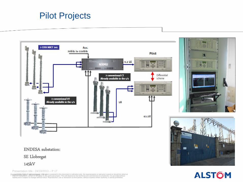
Pilot Project – ENDESA, Spain
ENDESA substation: SE Llobregat 145kV
Pilot Projects

© ALSTOM 2013. All rights reserved. Information contained in this document is indicative only. No representation or warranty is given or should be relied on that it is complete or correct or will apply to any particular project. This will depend on the technical and commercial circumstances. It is provided without liability and is subject to change without notice. Reproduction, use or disclosure to third parties, without express written authority, is strictly prohibited.
Presentation title - 24/10/2013 – P 18
Pilot Project – ENERGIENET, Denmark
ENERGINET: Denmark – Full digital solution 6 Underground 420 kV Cables differential monitoring
OHL 420kV 3000A RF 1.2
Diff 1
Cable 1 - 420kV 1500A - RF 2
> 20km
NXMU ’ s In : 3 currents
Out : 2x 61850 9 - 2LE
Diff 2
Redundancy Cable 2 - 420kV
1500A - RF 2 > 20km
9 - 2LE 9 - 2LE
9 - 2LE 9 - 2LE
MICOM P594 1PPS
MICOM P594 1PPS
AIS scope:
• 72 COSI CT420 • 24 COSI NXMU
SAS scope: • 24 P546 • 12 P594
x6

© ALSTOM 2013. All rights reserved. Information contained in this document is indicative only. No representation or warranty is given or should be relied on that it is complete or correct or will apply to any particular project. This will depend on the technical and commercial circumstances. It is provided without liability and is subject to change without notice. Reproduction, use or disclosure to third parties, without express written authority, is strictly prohibited.
Presentation title - 24/10/2013 – P 19
The Digital Substation: Conclusion
• The Digital Substation requires: − A common, coherent solution integrated using modern communication
architectures − An optimized solution for customers, with reduced costs of ownership and higher
performance • This is supported by the application of IEC 61850 within the substation :
− Digitization of data at source − Implementation of “real-time” communications − Integration of all control, measurement, protection and monitoring functions − Test features

www.alstom.com
With Alstom, preserve the environment.
Is printing this presentation really necessary?


