
Energy Research and Development Div is ion FINAL PROJECT REPORT
MICROGRID DEMONSTRATION PROJECT
DECEMBER 2012CEC ‐500 ‐2014 ‐045
Prepared for: California Energy Commission Prepared by: Sacramento Municipal Utility District

PREPARED BY: Primary Author(s): Mark Rawson Jeff Berkheimer Sacramento Municipal Utility District 6201 S Street Sacramento, California 95817-1899 Contract Number: 500-08-009 Prepared for: California Energy Commission Steve Ghadiri Contract Manager Fernando Pina Office Manager Energy Systems Research Office Laurie ten Hope Deputy Director ENERGY RESEARCH AND DEVELOPMENT DIVISION Robert P. Oglesby Executive Director
DISCLAIMER This report was prepared as the result of work sponsored by the California Energy Commission. It does not necessarily represent the views of the Energy Commission, its employees or the State of California. The Energy Commission, the State of California, its employees, contractors and subcontractors make no warranty, express or implied, and assume no legal liability for the information in this report; nor does any party represent that the uses of this information will not infringe upon privately owned rights. This report has not been approved or disapproved by the California Energy Commission nor has the California Energy Commission passed upon the accuracy or adequacy of the information in this report.

i
ACKNOWLEDGEMENTS
The authors wish to thank the Public Interest Energy Research Program for their support of this research. They would also like to thank the Consortium for Electric Reliability Technology Solutions and the following individuals for their invaluable help in performing the project work and preparing this document.
DE Solutions, Inc. .............................................. Keith Davidson
Energy Tech Consultants ................................. Rick Kuchenig
Integrated CHP Systems Corp. ....................... Gearoid Foley
National Renewable Energy Laboratory ....... Ben Kroposki and Mariko Shirazi
Peters Engineering ............................................ Jan Black
Sacramento Municipal Utility District ........... Jim Dayringer and Jim Ellering University of Wisconsin‐Madison Robert Lasseter

ii
PREFACE
The California Energy Commission Energy Research and Development Division supports public interest energy research and development that will help improve the quality of life in California by bringing environmentally safe, affordable, and reliable energy services and products to the marketplace.
The Energy Research and Development Division conducts public interest research, development, and demonstration (RD&D) projects to benefit California.
The Energy Research and Development Division strives to conduct the most promising public interest energy research by partnering with RD&D entities, including individuals, businesses, utilities, and public or private research institutions.
Energy Research and Development Division funding efforts are focused on the following RD&D program areas:
• Buildings End‐Use Energy Efficiency
• Energy Innovations Small Grants
• Energy‐Related Environmental Research
• Energy Systems Integration
• Environmentally Preferred Advanced Generation
• Industrial/Agricultural/Water End‐Use Energy Efficiency
• Renewable Energy Technologies
• Transportation
Microgrid Demonstration Project is the final report for the Microgrid Demonstration Project (contract number 500‐08‐009) conducted by Sacramento Municipal Utility District. The information from this project contributes to Energy Research and Development Division’s Energy Systems Integration Program.
For more information about the Energy Research and Development Division, please visit the Energy Commission’s website at www.energy.ca.gov/research/ or contact the Energy Commission at 916‐327‐1551.

iii
ABSTRACT
A micro grid is a network of generators linked together to serve buildings with electricity; some systems also provide heating and cooling. One advantage of a micro grid is reliability. A micro grid can operate while connected to the main utility grid and it can immediately disconnect if the power goes out. The microgrid still provides some electricity, heat, and cooling even when isolated from the utility. A microgrid can also offer customers higher quality power. The system can disconnect whenever the main grid’s power quality threatens the stable operation of sensitive equipment such as computers and other electronics.
This research demonstrated a microgrid at the Sacramento Municipal Utility District. The project involved the design, construction, and demonstration of a microgrid based on combined heat and power technology. The microgrid was integrated with the Sacramento Municipal Utility District’s central heating and cooling equipment, including a chilled‐water storage tank. A fast‐response static switch enabled the microgrid to isolate itself from the grid without electrical disturbances on either side and then reconnect when the utility restored high‐quality power. The project also included plans for commissioning the microgrid, monitoring its operation, analyzing the market for similar systems and disseminating research results.
Researchers planned to document any abnormal events and corrective actions taken once the microgrid is operating, as well as to explain what the data say about the microgrid’s performance. Researchers also intended to develop a plan to transfer the microgrid technology to key decision‐makers and the general public, and to implement a focused marketing program to educate customers in all market sectors about the benefits of combined heat and power.
Keywords: microgrid, combined heat and power, distributed energy resources, energy
Please use the following citation for this report:
Rawson, Mark; Jeff Berkheimer. (Sacramento Municipal Utility District). 2012. Microgrid Demonstration Project. California Energy Commission. Publication number: CEC‐500‐2014‐045.

iv
TABLE OF CONTENTS
Acknowledgements ................................................................................................................................... i
PREFACE ................................................................................................................................................... ii
ABSTRACT .............................................................................................................................................. iii
TABLE OF CONTENTS ......................................................................................................................... iv
LIST OF FIGURES .................................................................................................................................. vi
LIST OF TABLES .................................................................................................................................... vi
EXECUTIVE SUMMARY ........................................................................................................................ 1
Introduction ........................................................................................................................................ 1
Project Purpose ................................................................................................................................... 1
Project Results ..................................................................................................................................... 2
Project Benefits ................................................................................................................................... 3
CHAPTER 1: Introduction ...................................................................................................................... 5
1.1 Problem Statement ..................................................................................................................... 5
1.2 Project Goals and Research Objectives .................................................................................... 6
1.2.1 Goals .................................................................................................................................... 6
1.2.2 Research Objectives ........................................................................................................... 7
1.3 Project Approach ........................................................................................................................ 8
1.3.1 Introduction ........................................................................................................................ 8
1.3.2 Primary Tasks ..................................................................................................................... 8
CHAPTER 2: Preliminary Design ......................................................................................................... 9
2.1 Goals ............................................................................................................................................ 9
2.2 Load Analysis and Sizing ......................................................................................................... 9
2.2.1 Heating and Cooling Load Profiles ................................................................................. 9
2.2.2 Microgrid Sizing and Dispatch ...................................................................................... 11
2.2.3 Economic Analysis and Dispatch Economics .............................................................. 14
CHAPTER 3: Final Design and Construction ................................................................................... 16
3.1 Design Process .......................................................................................................................... 16
v
3.1.1 Goals .................................................................................................................................. 16
3.1.2 Design Approach ............................................................................................................. 16
3.2 Microgrid Functionality .......................................................................................................... 17
3.2.1 Grid‐Connected Operation ............................................................................................. 17
3.2.2 Grid‐Isolated (Island) Operation ................................................................................... 18
3.2.3 Major Microgrid Equipment ........................................................................................... 18
3.3 Construction ............................................................................................................................. 22
CHAPTER 4: Commissioning .............................................................................................................. 23
4.1 Introduction and Goals ........................................................................................................... 23
4.2 Mechanical Commissioning Plan ........................................................................................... 24
4.2.1 General ............................................................................................................................... 24
4.2.2 Products ............................................................................................................................. 30
4.2.3 Procedure .......................................................................................................................... 31
4.3 Electrical Commissioning Plan .............................................................................................. 39
4.3.1 General ............................................................................................................................... 39
4.3.2 Products ............................................................................................................................. 41
4.3.3 Procedure .......................................................................................................................... 42
4.4 Mechanical and Electrical Systems Acceptance Test .......................................................... 47
CHAPTER 5: Monitoring ...................................................................................................................... 48
5.1 Introduction and Goals ........................................................................................................... 48
5.2 Microgrid Instrumentation ..................................................................................................... 49
5.3 Data Acquisition System ........................................................................................................... 2
5.3.1 Data Acquisition System Support .................................................................................... 3
5.3.2 Data Analysis ...................................................................................................................... 3
CHAPTER 6: Demonstration ................................................................................................................. 5
6.1 Introduction and Goals ............................................................................................................. 5
6.2 Operational Test Results ........................................................................................................... 5
CHAPTER 7: Market Analysis ............................................................................................................... 6
vi
7.1 Introduction and Goals ............................................................................................................. 6
7.2 CHP Market Assessment .......................................................................................................... 6
7.2.1 Technical Potential ............................................................................................................. 6
7.2.2 Market Penetration ............................................................................................................ 8
CHAPTER 8: Technology Transfer ..................................................................................................... 11
GLOSSARY .............................................................................................................................................. 12
REFERENCES .......................................................................................................................................... 13
APPENDIX A: Appendices A‐Q ...................................................... A‐Error! Bookmark not defined.
LIST OF FIGURES
Figure 1: Representative Weekly Heating Profiles .............................................................................. 10 Figure 2: Representative Weekly Cooling Profiles .............................................................................. 11 Figure 3: Microgrid Dispatch (February) .............................................................................................. 12 Figure 4: Microgrid Dispatch (May) ...................................................................................................... 13 Figure 5: Microgrid Dispatch (August) ................................................................................................. 14 Figure 6: Schematic of Microgrid Instrumentation ............................................................................. 50 Figure 7: Market Penetration by Incentive Measure ............................................................................. 9 Figure 8: Comparison of Scenarios with Revised Market Acceptance Rates .................................. 10
LIST OF TABLES
Table 1: Microgrid Dispatch Economics ............................................................................................... 15 Table 2: Microgrid Instrumentation List ................................................................................................. 1 Table 3: Microgrid Instrumentation Description ................................................................................... 2 Table 4: Calculated Values ........................................................................................................................ 4 Table 5: Growth in Technical Potential Through 2030 .......................................................................... 7 Table 6: Technical Potential in 2030 ......................................................................................................... 8

1
EXECUTIVE SUMMARY
Introduction Providing reliable and uniform quality power to California electricity customers is challenging. Today’s commercial, industrial, and residential customers require better power quality and reliability than ever before. The technical upgrades needed to improve electric service are costly and cannot keep pace with demand from customers. Customers will increasingly need to look for advanced backup power and onsite generation to ensure self‐reliance.
The California Energy Commission and the U.S. Department of Energy have invested in research, development, and demonstration (RD&D) of technologies that support the microgrid. The microgrid is an advanced energy delivery concept that could enable the integration of an unlimited quantity of distributed energy resources into the electricity grid.
In a microgrid, distributed generators can operate in parallel with the utility grid or disconnected from it in an “island” mode. The microgrid system automatically disconnects from the utility power supply during major disruptions such as a fault or outage. The microgrid can also intentionally disconnect when the quality of power from the utility falls below certain standards. These flexible modes of operation allow microgrids to offer customers a more reliable, higher quality power supply. The recovery and use of waste heat from combined heat and power systems within the microgrid can increase the total efficiency of the system, making such a project more financially and environmentally attractive.
Commercial interest in microgrids has been increasing. This increased interest is being driven by the values of electricity customers and their power suppliers, including reliability, security, and the environmental sustainability of energy services. The microgrid concept also allows the value proposition of the energy service to be tailored to the customer.
The Consortium for Electric Reliability Technology Solutions is the main center for microgrid research. It addresses the technical and economic factors involved in microgrid design, control, energy management, protection, customer adoption and market size. International studies also focus on microgrids and their supporting technologies. Researchers at the consortium and elsewhere have made some progress on reducing the large costs associated with microgrids, such as the cost of safely interconnecting with the utility power supply but these costs are still high.
Project Purpose The goal of this project was to demonstrate a microgrid at the corporate headquarters of the Sacramento Municipal Utility District (SMUD). SMUD’s existing central utility plant served the corporate campus with chilled and hot water for space conditioning. This single‐customer, multi‐facility microgrid was designed to provide power to the central utility plant and the nearby field reporting facility. The microgrid system had a generation capacity of 300 kilowatts (kW). The microgrid could provide enough electricity and heat to maintain critical energy services including air‐conditioning and hot water to SMUD’s three buildings even when isolated from the utility during a power outage

2
Key research objectives of this project included:
• Demonstrating how a microgrid performs with real customers in a real‐world operating environment.
• Seamlessly separating and isolating the microgrid from the utility grid while maintaining power reliability and quality.
• Exploring how several components or functions could be integrated and interoperated within the microgrid system. One of these is demand response, where customers reduce their electricity consumption temporarily when the utility grid is running short of power generation capacity. Others are components such as internal combustion engines, solar photovoltaics and thermal energy storage.
• Determining whether microgrids could reduce the peak load of utility line that provides power by 20 percent.
• Determining whether a microgrid could provide economic value to customers, the utility, or both.
• Demonstrating that a microgrid could operate safely in island mode in a real‐world situation.
• Defining the technical and operational implications of exporting power from a microgrid in terms of the impact on the utility power distribution system.
• Exploring whether a microgrid could work with other distributed generation sources in other applications.
Project Results SMUD’s novel microgrid field demonstration linked natural gas‐fueled, internal combustion engines with a solar photovoltaic system. The first phase of the project involved confirming the proposed size of the microgrid system relative to the thermal and sensitive electrical loads to be served and consulting with researchers at the Consortium for Electric Reliability Technology Solutions to help understand past research findings and to define the logical next steps for the field demonstration to address, including the preliminary design.
The second phase involved designing and constructing the microgrid, including its mechanical and electrical systems and subsystems that protect the smartgrid from faults on the utility power supply. The microgrid was integrated with the Sacramento Municipal Utility District’s central heating and cooling equipment, including a chilled‐water storage tank. A fast‐response static switch enabled the microgrid to isolate itself from the grid without electrical disturbances on either side and then reconnect when the utility restored high‐quality power. This phase also demonstrated the microgrid’s ability to serve sensitive and non‐sensitive loads within SMUD’s central utility plant over a 12‐month demonstration period.
The microgrid’s functional design criteria were developed specifically for the system located at SMUD. However, the engineering team intended that the design could be used in other applications sensitive to power quality throughout the commercial, institutional, and industrial

3
sectors. The microgrid was designed to operate in two modes, either connected with the utility power supply or isolated from it.
This project addressed whether the microgrid technology being demonstrated could be applied successfully in other utility‐type applications where multiple customers were served by the microgrid. This assessment evaluated the extent to which such microgrids in SMUD’s power system could address rapidly growing demand, reduce peak loads, improve the utilization of the electricity distribution network, enable demand response and facilitate the inclusion of both renewable and nonrenewable distributed generation.
The next steps for this project were to develop a plan to transfer the microgrid technology to key decision‐makers and the general public. The following information must be available to successfully transfer the technology: knowledge gained throughout the project; experimental results from operating and monitoring the microgrid; and lessons learned from the microgrid demonstration experience.
Researchers also planned to assess the potential market to determine how extendable the microgrid concept would be to other parts of SMUD’s service territory. The assessment would characterize the types and sizes of microgrid applications and the cumulative megawatts of microgrid capacity that could be implemented.
Researchers also intended to implement a focused marketing program to educate customers in all market sectors about the benefits of combined heat and power and microgrids. SMUD’s territory has a high percentage of facilities in the education and government sectors, both of which are prime targets for combined heat and power thanks to customers’ tolerance with longer paybacks on their investment, so the potential market for such systems could be greater than 50 megawatts.
Project Benefits This project demonstrated the operation of a microgrid at a California utility. Successfully deploying microgrids could help ensure a more reliable power supply and higher quality power, as well as enabling the integration of an unlimited quantity of distributed energy resources into the electricity grid. Many of these distributed resources would be renewable energy sources that would reduce the emissions of greenhouse gases that cause climate change.


5
CHAPTER 1: Introduction 1.1 Problem Statement Providing uniform reliability and power quality to electricity customers in California is challenging utilities to find more efficient ways to use their assets while managing costs. Today’s commercial, industrial, and residential customers require better power quality and reliability than ever before. The technical upgrades needed to improve electric service, which are costly beyond what current regulations allow, cannot keep pace with demand from these customer sectors. Increasingly, these customers will need to look for sophisticated backup power and onsite generation to ensure self‐reliance.
The existing utility system is designed to deliver power from central station generating plants to the customer. Innovative power system designs are being developed and commercialized to incorporate large penetrations of distributed generation and other resources owned or operated by customers. But until these solutions are fully implemented, the benefits from distributed resources cannot be realized.
Clearly, due to the tremendous physical size and complexity of the electric transmission and distribution infrastructure, these challenges cannot be met by simply rebuilding or reconfiguring the system. But the power industry is working on ways to manage its existing infrastructure effectively while making the transition to the modern grid.
Public policies that seek to mitigate climate change reduce emissions of carbon dioxide and other pollutants, and reward renewable resources will continue to put pressure on the energy industry. Advanced technologies that support these policy goals are needed to improve end‐to‐end energy efficiency and to simplify the integration of non‐polluting distributed resources. Such technologies can also help reduce domestic dependence on fossil fuels such as natural gas. Market mechanisms and business models must evolve to facilitate the transition to these technologies.
The California Energy Commission and the U.S. Department of Energy’s Office of Electricity Delivery & Energy Reliability have invested in research, development, and demonstration of technologies that support an advanced energy delivery concept – the microgrid. This concept could enable the integration of, in principle, an unlimited quantity of distributed energy resources into the electricity grid. In a microgrid, distributed generators can operate in parallel with the utility grid or disconnected from it, in island mode.
The microgrid system automatically disconnects from the utility power supply during major disruptions, such as a fault or outage. But the microgrid can also intentionally disconnect when the quality of power from the utility falls below certain standards. Such power quality events include voltage sags and swells. By virtue of its flexible modes of operation, a microgrid can offer customers a more reliable, higher quality power supply. What’s more, the recovery and use of waste heat from combined heat and power (CHP) systems within the microgrid can

6
increase the total efficiency of the system, making such a project more financially attractive. The smaller size of emerging CHP packages lets the equipment be placed closer to the customer’s heating loads.
Recently, commercial interest in microgrids has increased, driven by the values of electricity customers and their power suppliers. Key among these values is the reliability, security, and environmental sustainability of energy services. Also, the microgrid concept allows the value proposition of the energy service to be tailored to the customer.
Microgrid technology has been researched principally under the auspices of the Consortium for Electric Reliability Technology Solutions (CERTS). This work has addressed the technical and economic factors involved in microgrid design, control, energy management, protection, customer adoption, and market size. (Please refer to this report’s Bibliography.) International studies have also focused on microgrids and their supporting technologies. Researchers at CERTS and elsewhere have made progress on reducing the costs associated with microgrids – such as the cost of safely interconnecting with the utility power supply – but these costs are still high.
1.2 Project Goals and Research Objectives 1.2.1 Goals The goal of this project is to demonstrate a microgrid at the corporate headquarters of the Sacramento Municipal Utility District (SMUD). SMUD’s existing central utility plant serves the corporate campus with chilled and hot water for space conditioning. The microgrid is designed to provide power to the central utility plant and the nearby field reporting facility (a single‐customer, multi‐facility application).
The existing central utility plant includes the following heating, ventilation, and air‐conditioning (HVAC) equipment:
• Two centrifugal chillers with 600 tons and 200 tons of cooling capacity
• Two hot water heaters each with a capacity of 5 million Btu per hour (Btu/h) capacity and two hot water heaters each with 1 million Btu/h capacity, for a total of 12 million Btu/h
• A thermal energy storage tank holding 760,000 gallons of chilled water with a cooling capacity of 15,000 tons per hour.
The storage tank is sized to carry the entire campus cooling load during on‐peak periods. A 21‐kilovolt‐amp (kVA) feeder supplies power to the central utility plant and field reporting facility. Should a fault occur on the feeder or upstream of it on the grid, the two buildings would be without power.
The microgrid system has a generation capacity of 300 kilowatts (kW). The equipment includes:
• Three 100‐kW Tecogen InVerde CHP units (INV‐100 reciprocating engine‐driven generators), which incorporate inverters that make them compatible with microgrid operation.

7
• A Thomas & Betts Smart Switch that can seamlessly isolate critical loads from the utility grid and transition back onto it.
• A 128‐ton Trane/Thermax absorption chiller.
• An existing 10‐kW solar photovoltaics (PV) system.
When isolated from the utility during a power outage, the microgrid can provide enough electricity and heat to maintain critical energy services to the two buildings, including air‐conditioning and hot water. The sensitive loads served by the microgrid include the primary pumps in the HVAC system, as well as controllers, selected cooling towers, lighting, and communication. The heat recovered from the Tecogen CHP units will provide hot water for space heating to the campus and will drive an absorption chiller linked directly to the thermal energy storage tank.
1.2.2 Research Objectives SMUD is addressing the following key research objectives through this project:
• Demonstrate how a microgrid performs with real customers in a real‐world operating environment.
• Seamlessly separate and isolate the microgrid from the utility grid, while maintaining power reliability and quality.
• Explore how the following components or functions can be integrated and interoperated within the microgrid system:
o Demand response
o Internal combustion engines
o PV
o Thermal energy storage.
• Determine whether microgrids can reduce the feeder’s peak load by 20 percent.
• Determine whether a microgrid can provide economic value to customers, the utility, or both.
• Demonstrate that a microgrid can operate safely in island mode in a real‐world situation.
• Define the technical and operational implications of exporting power from a microgrid, in terms of the impact on the utility power distribution system.
• Explore whether a microgrid can work with other distributed generation sources in other applications, such as –
o Hospitals.
o Manufacturing facilities.
o Community centers.
o Malls.

8
1.3 Project Approach 1.3.1 Introduction This project is being conducted in two phases. The first phase involves the microgrid design, development of the test plan, and outreach activities, as well as associated administrative work. The second phase involves the construction and demonstration of the microgrid. The work in Phase I must be completed to provide enough information for work in Phase II to comply with the California Environmental Quality Act.
1.3.2 Primary Tasks Besides administering the contract, the research team will perform the following primary tasks:
• Preliminary design
• Detailed design and construction
• Commissioning, including developing a commissioning test plan
• Monitoring
• Demonstration
• Market analysis
• Technology transfer.
Chapters 2—8 of this report describe work performed and progress made on these tasks.

9
CHAPTER 2: Preliminary Design 2.1 Goals The goals of the preliminary design work were to –
• Confirm the proposed size of the microgrid system relative to the thermal and sensitive electrical loads to be served.
• Consult with CERTS researchers to understand past research findings and define the logical next steps for the field demonstration to address, including the preliminary design.
The elements of the preliminary design work included –
• Equipment selection.
• Electrical and mechanical process and instrumentation diagrams.
• Protection system configuration.
• Site layout drawings.
• System control logic under normal and upset conditions.
• Power flow control.
The preliminary design discussed in this chapter was updated during the final design task (Chapter 3). Researchers submitted task reports on the energy load analysis (section 2.2) and the preliminary design.
2.2 Load Analysis and Sizing Researchers re‐evaluated the sizing of the CHP and absorption chiller system in terms of its ability to meet the loads served by SMUD’s central utility plant. This involved a detailed hourly analysis (8,760 hours, or 1 year) of the thermal and sensitive electrical loads of the utility plant and its neighboring facility. This interval analysis also involved assessing the best strategy for maximizing overall operational savings for the utility plant – specifically, charging the thermal energy storage tank, which holds chilled water for space cooling, and operating the absorption chiller optimally in conjunction with the chilled‐water storage. A commercial‐grade interval analysis model developed by Competitive Energy Insights was used for this analysis, and the annual costs for operation and maintenance (O&M) were estimated.
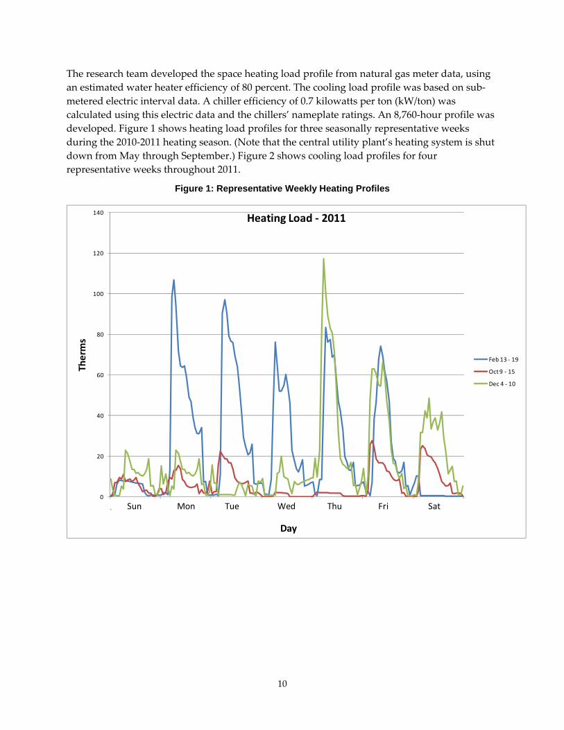
2.2.1 Heating and Cooling Load Profiles Understanding the hourly thermal and electric load profiles is important to properly sizing the CHP microgrid and operating it efficiently. Chilled water for space cooling, though dominated by electric chillers today, can be served in part by absorption chillers, which can be thermally driven by the heat recovered from a CHP system. In commercial and institutional applications, thermal loads can dictate the economic operating strategy of the CHP system because of their fluctuating nature, both daily (diurnally) and seasonally.
10
The research team developed the space heating load profile from natural gas meter data, using an estimated water heater efficiency of 80 percent. The cooling load profile was based on sub‐metered electric interval data. A chiller efficiency of 0.7 kilowatts per ton (kW/ton) was calculated using this electric data and the chillers’ nameplate ratings. An 8,760‐hour profile was developed. Figure 1 shows heating load profiles for three seasonally representative weeks during the 2010‐2011 heating season. (Note that the central utility plant’s heating system is shut down from May through September.) Figure 2 shows cooling load profiles for four representative weeks throughout 2011.
Figure 1: Representative Weekly Heating Profiles
0
20
40
60
80
100
120
140
.
Therms
Day
Heating Load ‐ 2011
Feb 13 ‐ 19
Oct 9 ‐ 15
Dec 4 ‐ 10
Sun Mon Tue Wed Thu Fri Sat

11
Figure 2: Representative Weekly Cooling Profiles
0
100
200
300
400
500
600
700
800
900
1
Tons
Day
Cooling Load ‐ 2011
Feb 20 ‐ 26
May 8 ‐ 14
Aug 7 ‐ 13
Nov 6 ‐ 12
Sun Mon Tue Wed Thu Fri Sat
2.2.2 Microgrid Sizing and Dispatch Any excess electricity generated by the microgrid would be exported back into the utility grid, so the electrical output did not enter into the sizing of the system, except for the need to power the critical loads in SMUD’s two buildings (central utility plant and field reporting facility). The analysis determined that three 100‐kW Tecogen CHP modules would fit this application, thermally and functionally. The Tecogen units selected are the InVerde model INV‐100, which is an inverter‐based, gas engine‐driven generator equipped with CERTS microgrid software. The CHP modules will mainly support the heating load during the colder months. During the cooling season, recovered heat from the CHP modules will drive a 128‐ton absorption chiller to support the buildings’ cooling load. At full load, the CHP system can deliver 282 kW (net of auxiliary loads) and about 2.1 million Btu of heat.
The CHP microgrid system will be operated via economic dispatch, determined from time‐varying electric and gas tariffs, thermal heating demand, and thermal cooling potential. In the interval analysis, the microgrid was modeled as if it were owned by one of SMUD’s secondary voltage commercial customers (rate GUS_M). Because this microgrid is a qualified CHP system,
12
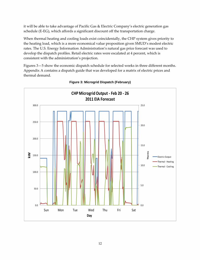
it will be able to take advantage of Pacific Gas & Electric Company’s electric generation gas schedule (E‐EG), which affords a significant discount off the transportation charge.
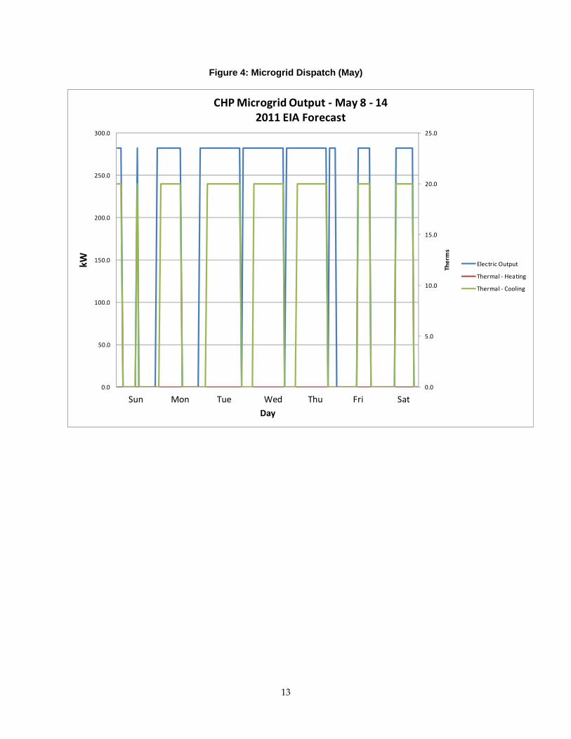
When thermal heating and cooling loads exist coincidentally, the CHP system gives priority to the heating load, which is a more economical value proposition given SMUD’s modest electric rates. The U.S. Energy Information Administration’s natural gas price forecast was used to develop the dispatch profiles. Retail electric rates were escalated at 4 percent, which is consistent with the administration’s projection.
Figures 3—5 show the economic dispatch schedule for selected weeks in three different months. Appendix A contains a dispatch guide that was developed for a matrix of electric prices and thermal demand.
Figure 3: Microgrid Dispatch (February)
0.0
5.0
10.0
15.0
20.0
25.0
0.0
50.0
100.0
150.0
200.0
250.0
300.0
1
Therm
s
kW
Day
CHP Microgrid Output ‐ Feb 20 ‐ 262011 EIA Forecast
Electric Output
Thermal ‐ Heating
Thermal ‐ Cooling
Sun Mon Tue Wed Thu Fri Sat
13
Figure 4: Microgrid Dispatch (May)
0.0
5.0
10.0
15.0
20.0
25.0
0.0
50.0
100.0
150.0
200.0
250.0
300.0
1
Therms
kW
Day
CHP Microgrid Output ‐May 8 ‐ 142011 EIA Forecast
Electric Output
Thermal ‐ Heating
Thermal ‐ Cooling
Sun Mon Tue Wed Thu Fri Sat

14
Figure 5: Microgrid Dispatch (August)
0.0
5.0
10.0
15.0
20.0
25.0
0.0
50.0
100.0
150.0
200.0
250.0
300.0
1
Therms
kW
Day
CHP Microgrid Output ‐ Aug 7 ‐ 132011 EIA Forecast
Electric Output
Thermal ‐ Heating
Thermal ‐ Cooling
Sun Mon Tue Wed Thu Fri Sat
2.2.3 Economic Analysis and Dispatch Economics According to the results of the economic dispatch model (Table 1), the CHP microgrid will achieve a full‐load capacity factor of 75 percent through the life of the project, which suggests attractive net annual cash flows.
Also, this high capacity factor, which includes downtime for scheduled and unscheduled maintenance, will help maintain the microgrid system in a fast transition mode in the event of a utility grid outage. The CHP units are capable of generating 25 percent of additional output (power boost) for demand management.

15
Table 1: Microgrid Dispatch Economics
EIA Gas Price Projection and Electric Price Escatation2010 2011 2012 2013 2014 2015 2016 2017 2018 2019
Fuel Costs ($140,505.13) ($149,782.02) ($154,872.44) ($158,242.81) ($165,796.22) ($174,156.03) ($183,848.88) ($193,880.48) ($204,931.41) ($218,156.78)Electric Revenues $223,948.65 $225,768.45 $231,148.32 $234,965.56 $238,935.49 $241,266.66 $245,499.15 $249,931.20 $254,409.14 $259,199.51Thermal Savings $37,086.47 $39,203.83 $40,340.81 $41,241.82 $43,044.11 $45,169.81 $47,454.55 $49,811.94 $52,415.20 $55,472.02Total Savings $120,529.99 $115,190.26 $116,616.69 $117,964.57 $116,183.38 $112,280.44 $109,104.82 $105,862.66 $101,892.93 $96,514.75Capacity Factor 75.9% 75.2% 75.9% 75.9% 75.9% 75.2% 75.2% 75.2% 75.2% 75.2%
2020 2021 2022 2023 2024 2025 2026 2027 2028 2029Fuel Costs ($231,296.11) ($242,928.73) ($253,609.11) ($255,339.37) ($262,871.88) ($266,635.07) ($277,556.17) ($293,036.55) ($312,117.24) ($324,552.97)Electric Revenues $262,356.08 $265,771.89 $272,853.41 $280,134.22 $286,183.52 $292,402.64 $298,710.83 $305,104.61 $311,922.79 $316,877.13Thermal Savings $58,580.91 $61,651.19 $63,837.69 $64,406.00 $66,220.59 $67,242.80 $69,840.64 $73,457.58 $77,827.80 $80,865.48Total Savings $89,640.88 $84,494.35 $83,081.99 $89,200.85 $89,532.23 $93,010.37 $90,995.30 $85,525.64 $77,633.35 $73,189.64Capacity Factor 74.5% 73.9% 74.5% 75.1% 75.2% 75.2% 75.2% 75.2% 75.2% 74.5%
NPV @ 6% $1,180,561.27Total Cash $1,968,445.09

16
CHAPTER 3: Final Design and Construction 3.1 Design Process 3.1.1 Goals The first goal of this task was to design the microgrid’s mechanical and electrical systems and subsystems. This equipment integrates the CHP modules, absorption chiller (absorber), chiller, pumps, cooling towers, and other microgrid components with SMUD’s existing central utility plant systems. The microgrid’s mechanical and electrical systems also control the microgrid equipment and protect it from faults on the utility power supply. Researchers submitted a task report on the final design.
This task’s second goal was to construct the microgrid using the specifications developed from the mechanical and electrical engineering design.
3.1.2 Design Approach The first objective was to build upon the preliminary design by developing a detailed set of drawings and specifications that could be issued for bid to construction contractors and equipment suppliers. The approach adopted for this project was to procure the major equipment in parallel with the design process. This would enable SMUD to –
1. Better control the selection of critical project equipment.
2. Fast‐track the construction process by pre‐ordering, ahead of the construction contract award, any equipment with a long lead time.
3. Test critical equipment for functionality prior to installation.
The pre‐purchased equipment included –
• A Thomas & Betts Smart Switch that can seamlessly isolate critical loads from the utility grid and transition back onto it.
• Three 100‐kW Tecogen InVerde CHP units (INV‐100 reciprocating engine generators), which incorporate inverters that make them compatible with microgrid operation.
• A 500‐ton Carrier electric chiller and Baltimore Air Coil cooling tower.
• A 128‐ton Trane/Thermax absorption chiller.
The original bid specification for the absorber called for it being packaged with pumps, valves, heat exchangers, and controls in an outdoor, skid‐mounted container. A companion cooling tower for installation on top of the package was also called for in the bid. However, when the bid turned out to be considerably higher than the budget allowed, the design team revised its approach. The new approach called for a stick‐built design for the absorber subsystem:
• The chiller would be pre‐packaged in a container for weather protection
• The pumps, heat exchangers, and valves would be mounted outside the chiller container.
17
• Instead of separate controls, the absorber subsystem would be controlled by the building automation system used in SMUD’s central utility plant, which is a Siemens direct digital control system.
• A cooling tower would be connected to the central utility plant to provide cooling water for the absorption chiller condenser and also for the engines whenever their recovered heat cannot be fully used.
This design perturbation increased design costs, caused the schedule to slip, and complicated the construction logistics. Furthermore, other design changes in the field resulted in additional drawing changes.
3.2 Microgrid Functionality The microgrid’s functional design criteria were developed specifically for the system located at SMUD. However, the engineering team intended that the design could be used in other applications sensitive to power quality throughout the commercial, institutional, and industrial sectors. The microgrid was designed to operate in two modes, either connected with the utility power supply or isolated from it.
3.2.1 Grid-Connected Operation During normal grid‐connected operation, the microgrid will be dispatched whenever its operation would benefit the customer economically – generally, whenever the buildings demand heating or cooling. The results of the energy profile analysis (section 2.2) indicate that the system will be dispatched for all but about 1,000 hours each year.
The following design principles will generally govern the microgrid’s operation when connected to the utility power supply:
• The CHP system (Tecogen modules and absorption chiller) will be connected to SMUD’s central utility plant at the 480‐Volt bus and to the nearby field reporting facility via a 21‐kV step‐up transformer. Electricity generated in excess of the demand at the two buildings will be exported back to the SMUD grid.
• Space heating will be the first thermal load dispatch priority, and cooling will be secondary. (Note that the heating system is shut off between May and September.)
• When in the cooling mode, the CHP system’s absorption chiller will charge the thermal energy storage tank. In the absence of a heating load, the absorber will be dispatched whenever two or all three of the Tecogen units are operating. The electric chillers will provide supplementary cooling during off‐peak hours to charge the tank.
• Even though the Tecogen units will have an availability factor of at least 92 percent, one of the three units will be down for maintenance or repair for an appreciable part of the year (up to 2,000 hours total).
• The absorption chiller is sized to operate off the recovered heat from two or all three Tecogen units. This chiller would shut down when only a single Tecogen unit is running.

18
• The microgrid system’s ability to dump heat through the cooling tower will enable full‐load CHP system operation regardless of the demand for heat.
3.2.2 Grid-Isolated (Island) Operation When in island mode, isolated from the utility power supply, the microgrid will operate according to the following design principles:
• Upon a grid interruption to the central utility plant and field reporting facility, the microgrid’s CHP system will seamlessly transition to island mode. The two buildings’ noncritical loads will be tripped off line. Noncritical loads include the electric chillers and if necessary the air compressor, the elevator, and selected air‐conditioning loads in the field reporting facility.
• The buildings’ critical and sensitive loads are expected to stay below the power capability of two of the three Tecogen units (if one unit is down for maintenance or repair), according to the results of the energy load analysis (section 2.2) and other data. However, should the power demand exceed the capacity of the operating generators after an interruption in the utility power supply, the field reporting facility will be tripped off line, and the Tecogen units will serve only the central utility plant loads.
• The central utility plant will be served from the three Tecogen units through the 480‐Volt bus. The 21‐kV step‐up transformer will be used to power the field reporting facility.
• Recovered engine heat will be used for space heating or cooling as needed. Unused heat will be dumped to the outdoors.
• The microgrid CHP system will automatically resynchronize with the SMUD grid when the feeder is re‐energized.
3.2.3 Major Microgrid Equipment The functional specifications for the microgrid’s three major components – the smart switch, the three CHP modules, and the absorption chiller – are summarized below (sections 3.2.3.1—3.2.3.3). The following appendices contain the design drawings, specification documents, and other additional information on these three components, the microgrid system, and other equipment:
• Appendices B—D provide details on the smart switch, CHP modules, and absorption chiller.
• Specifications for the microgrid’s electric chiller and cooling tower appear in Appendices E and F.
• Appendix G presents the schematic design drawing set for the microgrid.
• Appendices H and I contain the microgrid’s mechanical and electrical drawings and specifications.
• Appendix J presents the control system’s sequence of operation.
19
3.2.3.1 Smart Switch The Thomas & Betts Smart Switch will provide the interface between the utility system and the microgrid’s CHP units – that is, between SMUD’s power supply and the microgrid’s critical loads. The functional specifications of the smart switch are as follows:
• The smart switch will disconnect from the utility system for power quality events and for events defined under –
o The California Public Utilities Commission’s Rule 21 as it applies to SMUD. Rule 21 is a tariff that describes the interconnection, operating, and metering requirements for generation facilities to be connected to a utility’s power distribution system. SMUD voluntarily uses the technical requirements of Rule 21 for its own interconnection tariff.
o The Institute of Electrical and Electronics Engineers (IEEE) 1547 standard, which provides uniform requirements for interconnecting distributed resources with electric power systems. These requirements are relevant to the interconnection’s performance, operation, testing, safety, and maintenance.
• The smart switch will separate for a utility system disturbance that is not defined as an event by SMUD’s Rule 21 or IEEE 1547, but which is defined as a power quality event by the ITIC/CBEMA curve. The maximum designed response time for the smart switch will be ½ cycle (8 milliseconds).
o ITIC is the International Technology Industry Council, an organization for information and communications technology. The Computer and Business Equipment Manufacturers Association (CBEMA) was ITICʹs predecessor organization
o The ITIC/CBEMA curve describes the alternating‐current (AC) input voltage envelope that sensitive electronic equipment such as computers, office equipment, and industrial machinery can tolerate. Electronic equipment is able to withstand smaller voltage deviations for longer periods of time and vice versa. For example, a 5 percent voltage variation can be consistently withstood by most electronic equipment. Likewise, large voltage spikes can be tolerated if they are of a short enough duration (well under a single cycle).
• The smart switch will include a digital system processor that monitors the power on both sides of the switch and initiates islanding from the utility system and reconnecting to it, also seamlessly and automatically. The processor will provide on/off commands for the semiconductors and will control the circuit breakers.
• The digital system processor will locally monitor the voltage, current, and frequency on both sides of the smart switch to determine when to initiate the open and close commands to the switch. All potential transformers and current transformers required for monitoring the power on both sides of the switch will be provided within the switch.
• To calculate power flow, the digital system processor will also be able to accept signals from the current transformer from the point of common coupling with the utility

20
system. Power flow will be used for the anti‐islanding protection required per SMUD’s Rule 21 and IEEE 1547.
• When initiating a close command with power on both the utility‐line side and distributed‐load side of the smart switch, the digital system processor will not be required to provide frequency and voltage control commands to the microgrid’s loads. The processor will only need to provide a close command supervised by the processor’s synchronizing check element. The parameters for the synchronizing check element are defined in SMUD’s Rule 21 and IEEE 1547.
• The smart switch will include a selector switch with three positions (Local, Off, and Remote) and a two‐position selector switch (Normal and Bypass). These controls function as follows:
o Local. The digital system processor has complete control of the smart switch.
o Off. The smart switch is out of service. The semiconductors are de‐energized, and the input, bypass, and output circuit breakers are open.
o Remote. The digital system processor will accept open and close commands from the human/machine interface. Closing back to the utility system must be initiated by a person. However, the synchronizing check function will be provided by the processor, which will initiate the close command.
o Normal. The input and output circuit breakers are closed, the bypass circuit breaker is open, and the semiconductors are energized. The digital system processor has complete control of the smart switch.
o Bypass. The input and output circuit breakers are open, the bypass circuit breaker is closed, and the semiconductors are de‐energized. When switching from the Bypass mode to the Normal mode, the digital system processor will initiate this transfer in a seamless manner. The processor will automatically switch to the Bypass mode should there be a component failure within the smart switch that prevents the switch from functioning as designed.
• The digital system processor will include the following protection functions as defined by the American National Standards Institute (ANSI) and will initiate control commands when these functions are not in compliance with SMUD’s Rule 21 and IEEE 1547:
o 25 – Synchronizing check
o 27 – Under voltage
o 32 – Reverse/under power
o 50 – Instantaneous over‐current
o 51 – Time over‐current
o 59 – Over voltage
o 79 – Reconnection time delay
o 81O – Over frequency
o 81U – Under frequency.

21
• The smart switch will interface with a supervisory control and data acquisition system (commonly called a SCADA system) for the functions of controlling, alarming, event reporting, trending, and data archiving.
3.2.3.2 CHP Modules The functional specifications of each of the microgrid’s three natural gas‐fueled CHP modules are as follows:
• Gross continuous power rating of 100 kW.
• Usable thermal output of 700,000 Btu/h at full load.
• Efficiency (based on the natural gas fuel’s higher heating value, which is a more rigorous measure than its lower heating value) –
o 27 percent electric
o 82 percent overall.
• Air emissions, excluding any heat recovery credit –
o Nitrogen oxides, 0.075 grams per brake‐horsepower per hour (g/bhp‐hr). This is equivalent to 0.3 pounds of nitrogen oxides emissions per megawatt‐hour of energy generated (lb/MWh).
o Carbon monoxide, 0.6 g/bhp‐hr (2.0 lb/MWh)
o Non‐methane hydrocarbons: 0.15 g/bhp‐hr (0.5 lb/MWh).
• Standardized interconnection.
• Black start, which is the ability to start up instantaneously without electricity from the utility grid.
• Premium‐quality waveform, voltage, and power factor.
• High part‐load efficiency, due to the engine’s ability to operate at variable speeds, which is in turn enabled by the CHP module’s inverter.
• Simple controls shared among the three Tecogen units.
• Product listed by Intertek and in compliance with the Underwriters Laboratories (UL) 1741 standard, which covers inverters and interconnection equipment used in power systems that are not grid‐connected.
3.2.3.3 Absorption Chiller The absorber and its ancillary equipment are protected from the weather by a permanent weatherproof enclosure that allows access to all serviceable components. The functional specifications of the microgrid’s absorption chiller are as follows:
• The Trane/Thermax single‐effect hermetic absorption liquid chiller is designed to use relatively low‐temperature hot water as its energy source. The chiller is rated for a hot‐water inlet temperature of 207°F (97.2°C) and an outlet temperature of 183°F (83.9°C). The chiller includes a vacuum pump, refrigerant solution, and a hot‐water control valve.

22
• The chiller is rated at 128 tons of cooling capacity in accordance with the 560‐2000 standard issued by ANSI and the Air‐conditioning & Refrigeration Institute. The chiller is manufactured in accordance with the latest edition of Standard 15 issued by ANSI and ASHRAE (the American Society of Heating, Refrigerating and Air‐conditioning Engineers). The chiller will be UL‐certified and will be constructed in accordance with UL requirements.
• The control system will automatically adjust the input hot‐water flow rate to the chiller and modulate the flow proportional to the chilling load. The controls will automatically maintain the chilled‐water set point temperature by adjusting the diverting valve and controlling the refrigerant pump.
• The chiller can operate continuously from 100 percent to 66 percent of its design capacity.
3.3 Construction The microgrid was constructed as designed and specified. The schedule was delayed by the design perturbation described above (section 3.1.2).

23
CHAPTER 4: Commissioning 4.1 Introduction and Goals The goal of this task is to develop a test plan for commissioning the operation of SMUD’s microgrid and to conduct that testing. Five subtasks comprise this work:
1. Subtask 4.1: Commissioning Test Plan
2. Subtask 4.2: Pre‐Commissioning Test of Smart Switch
3. Subtask 4.3: Power and Voltage Control Tests
4. Subtask 4.4: Tests of Transfer Between Parallel and Island Modes
5. Subtask 4.5: Protection Testing
The commissioning test plan includes subjecting the microgrid to various simulated power quality and utility grid disturbances. Researchers will test the microgrid in both parallel and island modes and will collect performance data. The test plan will also specify what data need to be collected for the field demonstration. Researchers submitted a task report on the commissioning test plan.
Functional commissioning tests (Subtasks 4.3—4.5) will assess whether the microgrid controls, when the system is islanded, are able to regulate –
• Power flow on the microgrid as loads on the system change their operating points.
• The voltage at the interface of each Tecogen unit as loads on the microgrid system change.
These functional tests will also verify whether each Tecogen unit is able to rapidly pick up its share of the load when the system islands.
In addition to these control functions, an important operational function is the ability of the microgrid to island smoothly and to reconnect automatically to the utility power supply. The Thomas & Betts Smart Switch provides this function.
Several appendices contain details on the various documents that were used during the testing and commissioning of the microgrid:
• Appendix K provides a sensor calibration form and pre‐commissioning checklists for the microgrid’s mechanical and electrical systems.
• Appendix L presents the results of pre‐commissioning tests conducted by the National Renewable Energy Laboratory.
• Appendix M provides startup guidelines for the microgrid’s chilled and hot water systems.
• Appendix N shows the equipment sequence of the operation monitoring plan.

24
4.2 Mechanical Commissioning Plan Mechanical systems commissioning will –
1. Verify the operation and functional performance of all mechanical systems for compliance with design documents.
2. Document all mechanical system tests and inspections.
3. Verify application of O&M manuals, as‐built documents (drawings with authorized revisions), spare parts listing, special tools listing, and other items as may be specified for support of mechanical systems and equipment.
4. Coordinate and direct training for SMUD’s personnel to conduct O&M of mechanical equipment and systems.
4.2.1 General 4.2.1.1 Work and Related Work The work to be performed during mechanical commissioning includes specifying the requirements for pre‐balance, startup, and commissioning of the microgrid’s mechanical systems. These systems and equipment include (but are not limited to) the following:
1. Chilled water
2. Heated water
3. Glycol water
4. Cooling tower water
5. Sand filtration
6. Direct digital controls
7. Life safety
8. Electrical systems (see section 4.3)
9. Absorption chiller
10. Dry cooler
11. Smart switch.
This work also includes the requirements for the following procedures to be performed on the microgrid’s mechanical systems:
1. Pre‐balance
2. Initial startup
3. Controls testing
4. Commissioning
5. Intermediate balancing
6. Final balancing.

25
Other related work includes following ASHRAE 1‐1989, Guideline for Commissioning of HVAC Systems.
Electrical system commissioning is described below (section 4.3). In addition, the mechanical and electrical systems will undergo a 72‐hour acceptance test (section 4.4).
4.2.1.2 Definitions Commissioning is a systematic process confirming that all mechanical and electrical systems have been installed, properly started, and consistently operated in strict accordance with the contract documents. Commissioning also confirms that all systems are complete and functioning in accordance with the contract documents at substantial completion and that the contractor has provided the owner with adequate system documentation and training. Commissioning includes deferred and/or seasonal tests as approved by the owner.
The commissioning plan is defined as an overall plan, developed by the Certified Commissioning Authority and/or the contractor that provides the structure, schedule, and coordination planning for the commissioning process from the construction phase through the warranty phase. The commissioning plan must be approved by SMUD and must satisfy the owner’s test requirements.
The commissioning team is a working group made up of representatives from the architect/engineering firm, the contractor, the balancing agency, the provider of the building management system, specialty manufacturers and suppliers, and SMUD. The contractor will provide ad‐hoc representation of subcontractors on the commissioning team as required.
The system owner is a SMUD representative who is responsible for any changes to, or maintenance of, the microgrid system’s capacity, reliability, integrity, and overall long‐range plan.
The project manager is a SMUD representative who is responsible for managing the project’s schedules, costs, and construction.
The quality assurance/quality control inspector is a SMUD representative who is responsible for reviewing and approving the electrical/mechanical installations for design compliance. This inspector must sign off at three levels:
1. Level 1, safety sign‐off. A review of electrical/mechanical facilities systems and subsystems associated with the equipment or process must be completed prior to any hazardous energies being introduced. This includes a review of disconnects, isolation and relief valves, guarding of energized circuits, and emergency shutdown capabilities.
2. Level 2, equipment sign‐off. All Level 1 items must be completed. All environmental health and safety requirements must have been reviewed, including labeling and interlocks.
3. Level 3, project turnover. All Level 1 and 2 items must be completed. All punchlist items and specifications must have been completed and the systems ready for full operation. Completion of this system startup and commissioning specification is a component of, but not limited to, achieving Level 3 project turnover.

26
A pre‐functional test occurs before startup and functional testing. Pre‐functional checklists augment the manufacturer’s startup checklist and are combined with them. All pre‐functional checklist items must be satisfactory before startup can proceed.
Pre‐functional tests are primarily static inspections and procedures that prepare the equipment or system for initial operation. They can include, for example, tests of belt tension, oil levels, and labels affixed, gauges in place, and sensors calibrated. However, some pre‐functional checklist items entail simple testing of the function of a component or a piece of the equipment or system, such as measuring the voltage imbalance on a three‐phase motor
Pre‐functional checklists must include the manufacturers’ startup checklists. The contractor must sign pre‐functional checklists as complete and submit them with a form requesting startup and functional testing.
Startup is the step where the equipment is initially energized, tested, and operated. Startup is completed before functional testing begins.
Functional testing involves performance testing of the dynamic functions and operations of the equipment and systems, using manual (direct observation) or monitoring methods. Functional tests are performed after pre‐functional checklists and startup is complete.
Functional testing is the dynamic testing of whole systems, rather than just their components, under full operation. For example, the chiller pump is tested interactively with the chiller functions to see if the pump ramps up and down to maintain the differential pressure setpoint.
Systems are tested under various modes, such as during low cooling or heating loads, high loads, component failures, unoccupied space, varying outside air temperatures, and power failure. The systems are run through all the control system’s sequences of operation (Appendix J), and the components are verified to be responding as the sequences state that they should.
Manual testing uses handheld instruments, immediate control system readouts, or direct observation to verify performance. This is in contrast to analyzing monitored data taken over time to make the observation.
In simulated condition testing, a condition is created for the purpose of testing the response of a system, such as raising or lowering the setpoint of a sensor. Similarly, during a simulated signal test, a sensor is disconnected and a signal generator is used to simulate a sensor value for the purpose of testing a full range of conditions.
Test requirements specify what systems, modes, and functions must be tested. They also define the acceptable range of performance levels that must be met. Test requirements are not the same as detailed test procedures. Test requirements and acceptance criteria are specified in the contract documents.
Trending tests involve monitoring, using the building energy management system or other data acquisition system. Data gathered over a period of time are compiled for analysis.

27
Sensor and actuator calibration is another type of commissioning test. All field‐installed temperature and pressure sensors and gauges, flow meters, and actuator valves on all equipment must be calibrated. The test engineers must also verify that all locations are appropriate and distant enough from potential causes of erratic operation.
Deferred tests are performed after the project is substantially complete. The tests are deferred because equipment acceptance is only partial or because of seasonal requirements or other site conditions that prohibit the test from being performed earlier in the schedule.
4.2.1.3 Documentation The following information must be provided to the Certified Commissioning Authority or the contractor to include in the commissioning plan:
1. Plan for delivery and review of submittals, system manuals, and other documents and reports.
2. Identification of installed systems, assemblies, equipment, and components including design changes that occurred during the construction phase.
3. Process and schedule for completing construction checklists and manufacturers’ pre‐start and startup checklists for HVAC and refrigeration (HVAC&R) systems, assemblies, equipment, and components to be verified and tested.
4. Certificate of completion certifying that installation, pre‐start checks, and startup procedures have been completed.
5. Certificate of readiness certifying that HVAC&R systems, subsystems, equipment, and associated controls are ready for testing.
6. Test and inspection reports and certificates.
7. Corrective action documents.
8. Verification of testing, adjusting, and balancing reports.
In addition, certain documents associated with electrical system commissioning (section 4.3) also are required. These include draft reports from the electrical testing agency, which must be reviewed and provided to SMUD with comments, and final reports from the agency, which must be reviewed by the subcontractor.
The work performed during mechanical systems commissioning applies to all equipment installed by the contractor, including pre‐purchased and existing equipment provided by SMUD.
The contractor will prepare the following documents and have them ready prior to startup and commissioning:
1. Project plans and specifications (contract documents), authorized revisions (record drawings), mechanical equipment shop drawings and submittals (approved), test and balance reports, equipment startup and certification reports, and other documents.

28
2. Records of inspections by the required code authorities, sign‐off documents, and other records.
3. Calibration reports for all instruments. These must include the method of calibration and the calibration standards used. Where required, the reports must provide traceability in accordance with the National Institute of Standards and Technology.
4.2.1.4 Quality Assurance The contractor must allow adequate time in the schedule to provide a thorough and systematic checkout, in addition to the following:
1. Mechanical/plumbing. Inspections and certifications by the contractor, SMUD, and the vendor assure that the manufacturers’ recommended startup of all equipment has been properly completed.
2. Electrical. Inspections and certifications by the contractor, SMUD, and vendor assure that all the manufacturers’ and SMUD’s recommended electrical testing has been successfully completed (see section 4.3). Additionally, startup and energizing of the equipment must be properly completed.
3. Mechanical/plumbing/electrical/controls. The contractor, SMUD, and the engineering firm walk by all systems to verify that they are as specified in the current contract documents and are acceptable.
4. Controls. Hardware installation and associated instrument terminations/loop check and calibration are completed. Software is complete and loaded. Testing of all systems that interface with the control system is complete.
5. Life safety. All life safety devices are installed, tested, and viewed by the contractor, SMUD, and the engineering firm to verify that they are as specified in the current contract documents and are acceptable.
4.2.1.5 Scope The microgrid’s mechanical commissioning plan will verify that –
• Equipment and systems are installed according to the manufacturer’s recommendations and to the minimum standards accepted by the industry.
• The equipment and systems are performing properly and are documented.
• The O&M documentation left onsite is complete.
• The owner’s operating personnel are adequately trained.
The mechanical commissioning plan also includes data logging. Test engineers will monitor and record flows, currents, status, pressures, and other variables of the equipment using either (1) stand‐alone data recorders that are separate from the control system or (2) the trending capabilities of the control system.
All of the test procedures will be fully documented on the pre‐functional checklists or in other suitable forms such as an appendix. This documentation will clearly reference the procedures followed and will state the initial, intermediate, and final results.

29
Functional testing and verification can be achieved either by manual testing or by monitoring the system’s performance and analyzing the results. Results can be analyzed using the control system’s trend log capabilities or by stand‐alone data loggers, as noted above.
Calibration methods and results will be submitted to SMUD. All test instruments will have had a certified calibration performed within the last 12 months, and they must comply with all local, state, and federal requirements and certifications. Sensors installed in the equipment at the factory need not be calibrated in the field as long as their calibration certification is provided.
Overriding sensor values to simulate a condition is allowed, but this method would be used with caution and avoided when possible. An example is overriding the outside air temperature reading in a control system to be something other than it really is. Sensors, transducers, and other devices must be calibrated before any conditions are simulated or any values are overridden.
Another way to test a sequence is by altering the setpoints. This technique might be used instead of overriding sensor values or when simulating conditions is difficult.
4.2.1.6 Safety Prior to system startup, the contractor is responsible for obtaining all of the lock‐out/tag‐out procedures from SMUD. All tags and locks will be provided by the contractor.
Also before startup, the contractor must ascertain that all of the equipment has been installed complete with all safety devices required by the Occupational Safety and Health Administration, the American Society of Mechanical Engineers, the National Fire Protection Association, the National Electrical Code, and all local, state, and federal codes and regulations. All safety devices must be checked for proper installation and, in cases where nondestructive operation is feasible, checked for proper operation.
The contractor must at all times keep all guards in place and adjusted so as to provide protection to personnel and equipment. These include belt guards, drive coupling guards, electrical insulator guards, and other equipment guards. Where an unsafe working condition is observed by the contractor, the contractor must correct that unsafe condition and inform SMUD of its existence and the measures taken to correct the hazard.
The startup requirements provided in these specifications are not intended to require the contractor to act in a manner that would violate the provisions of warranties and guarantees or create a safety hazard to personnel or property. The contractor will indicate in the startup report any startup actions that were not taken due to warranty or safety considerations.
4.2.1.7 Submittals The contractor will submit three copies of the commissioning plan to SMUD for approval before starting the commissioning process. The plan must include at a minimum the following information:
1. Schedule
2. Sequence

30
3. Documentation requirements
4. Verification procedures
5. Staffing requirements
6. Levels 1 and 2 sign‐off
7. Pre‐commissioning checklists
8. Training plan
9. Tool list.
After commissioning is complete, the contractor must submit six copies to SMUD of all documentation obtained during the commissioning process. This documentation will be organized in letter‐size three‐ring binders complete with an index page and indexing tabs. The binders will be labeled on the front cover and side. The final documentation must include at a minimum the following items:
1. Equipment inspection reports
2. Levels 1 and 2 signed‐off checklists
3. Equipment startup certificates
4. Equipment testing and balancing reports
5. Mechanical design compliance reports
6. Electrical test reports (see section 4.3)
7. Code inspection certificates
8. Instrumentation calibration reports
9. Sequence of operation
10. Completion certificate for the 72‐hour electrical/mechanical systems acceptance test
11. Pre‐commissioning checklists
12. Final HVAC balance reports. 4.2.2 Products 4.2.2.1 Instrumentation All of the instrumentation needed for system startup and commissioning must be provided by the contractor or agency performing the tests. Instruments will be operated by the individual testing contractor or agency as requested.
4.2.2.2 Tools All of the tools needed for system startup and commissioning must be provided by the contractor or agency performing the tests. Tools will be operated by the individual testing contractor or agency as requested.

31
4.2.3 Procedure 4.2.3.1 General The contractor will be responsible for all coordination, scope development, scheduling, and documentation for mechanical system commissioning. The contractor will provide an individual to organize and lead the commissioning team with the proper participants.
The contractor and personnel involved in commissioning will actively participate in the construction phase of the project to ensure compliance with the mechanical system commissioning requirements.
The commissioning team will consist of (but is not limited to) representatives from the contractor and SMUD. The project manager, SMUD technicians, safety personnel, and customer representatives can be included on the commissioning team as required (see section 4.2.1.2).
4.2.3.2 Testing Preparation To prepare for testing, the team must certify that –
• HVAC&R systems, subsystems, and equipment have been installed, calibrated, and started and are operating according to the contract documents.
• HVAC&R instrumentation and control systems have been completed and calibrated and that they are operating according to the contract documents, and that pre‐test setpoints have been recorded.
• Testing, adjusting, and balancing procedures have been completed and that testing, adjusting, and balancing reports have been submitted, discrepancies corrected, and corrective work approved.
In addition, the team must –
• Set systems, subsystems, and equipment into operating mode to be tested. Modes include normal shutdown, normal automatic position, normal manual position, unoccupied cycle, emergency power, and alarm conditions.
• Inspect and verify the position of each device and interlock identified on the checklists.
• Check safety cutouts, alarms, and interlocks with smoke control and life safety systems during each mode of operation.
• Install test instrumentation including measuring instruments and logging devices to record test data as directed by the Certified Commissioning Authority.
4.2.3.3 Testing and Balancing Verification Before the testing and balancing work begins, the team must provide copies of reports, sample forms, checklists, and certificates to the Certified Commissioning Authority. The team must also notify the authority at least 10 days in advance of the testing and balancing work and must provide access for the authority to witness it.
At the authority’s direction, the team must provide technicians, instrumentation, and tools to verify testing and balancing of the HVAC&R systems. The authority will notify the testing and balancing contractor or subcontractor 10 days in advance of the date of field verification. Notice

32
will not include data points to be verified. The contractor or subcontractor will use the same instruments (by model and serial number) that were used when original data were collected.
Failure of an item will result when the item deviates from its expected performance by more than 10 percent. Failure of more than 10 percent of selected items will result in rejection of the final testing, adjusting, and balancing report.
For sound pressure readings, a deviation of 3 decibels will result in rejection of final testing. Variations in background noise must be considered. The team must remedy the deficiency and notify the authority so that verification of failed portions can be performed.
4.2.3.4 General Testing Requirements The team must provide technicians, instrumentation, and tools to perform commissioning tests at the direction of the Certified Commissioning Authority.
The scope of HVAC&R testing will include the entire HVAC&R installation, from central equipment for heat generation and refrigeration through distribution systems to each conditioned space. Testing will include measuring the capacities and effectiveness of the operational and control functions.
The team must test all operating modes, interlocks, control responses, and responses to abnormal or emergency conditions, and it must verify the proper response of the building automation system’s controllers and sensors.
The Certified Commissioning Authority, along with the contractors or subcontractors responsible for HVAC&R equipment, testing and balancing, and HVAC&R instrumentation and control, will prepare detailed testing plans, procedures, and checklists for HVAC&R systems, subsystems, and equipment.
Tests will be performed using design conditions whenever possible. However, simulated conditions may need to be imposed using an artificial load when it is not practical to test under design conditions. Before simulating conditions, the team must –
1. Calibrate the testing instruments.
2. Provide equipment to simulate loads.
3. Set simulated conditions as directed by the commissioning authority.
4. Document simulated conditions and the methods of simulation.
After tests, the settings should be returned to normal operating conditions.
The Certified Commissioning Authority can direct that setpoints be altered when simulation is not practical. The authority can also direct that sensor values be altered with a signal generator when other methods are not practical.
If tests cannot be completed because of a deficiency outside the scope of the HVAC&R system, the team must document the deficiency and report it to the system owner. After deficiencies are resolved, the tests can be rescheduled. If the testing plan indicates specific seasonal testing, the

33
team must complete the appropriate initial performance tests and documentation and schedule the seasonal tests.
4.2.3.5 Systems, Subsystems, and Equipment Testing Procedures The HVAC&R instrumentation and control system testing will be performed by the balancing contractor and administered by the Certified Commissioning Authority.
Pipe system cleaning, flushing, hydrostatic tests and chemical treatment requirements are specified in the piping sections by the contractor. The mechanical contractor must prepare a pipe system cleaning, flushing, and hydrostatic testing plan and must provide the plan and final reports to the authority.
4.2.3.6 Energy Supply System Testing At the direction of the Certified Commissioning Authority, the team must provide technicians, instrumentation, tools, and equipment to test the performance of the chilled‐water, condenser‐water, and hot‐water systems and equipment. The authority will determine the sequence of testing and the testing procedures for each piece of equipment.
4.2.3.7 Refrigeration System Testing The team must provide technicians, instrumentation, tools, and equipment to test the performance of the chillers, cooling towers, and condensers. The Certified Commissioning Authority will determine the sequence of testing and the testing procedures for each piece of equipment and pipe section to be tested. For piping distribution system testing, the team must provide technicians, instrumentation, tools, and equipment to test the performance of the hydronic distribution systems or other distribution systems.
4.2.3.8 System Verification Checks System verification checks ensure that systems have been installed properly, conform to the specifications, and are ready for safe startup. The responsibility for carrying out these checks, as well as any corrective action, lies with the contractor. Documentation of these checks depends on project specifications. The Certified Commissioning Authority prepares the system verification checks as part of the commissioning plan.
4.2.3.9 Controls Point-to-Point Checks The automatic temperature controls contractor carries out point‐to‐point control checks and documents the results on checkout sheets. These checks confirm that all control‐point wiring has been correctly installed and terminated, sensors have been calibrated, and field devices operate correctly. This involves physical observation of device responses by the automatic temperature controls contractor to ensure they match control system displays. The Certified Commissioning Authority verifies the results reported by the contractor and includes this information in the commissioning report. Commissioning authorities frequently employ sampling techniques to document verification of point‐to‐point checkouts. Direct monitoring of the checkout process for the direct digital control system facilitates conformance with the design intent.

34
4.2.3.10 HVAC System Startups The mechanical contractor is responsible for starting the HVAC equipment and systems in accordance with the project specifications. Owner representatives should be invited to all equipment startups. No equipment should be started until the appropriate documentation from the commissioning plan has been completed and the startup time and date have been scheduled and approved in advance by all parties.
Before starting equipment or systems, contractors must complete the relevant system verification checks. When required by the specification, the manufacturer’s certified technician, using the manufacturer’s formal startup procedure and documentation, must perform the startup. The Certified Commissioning Authority should observe all major startups. Any abnormalities occurring or corrective actions taken during startup of equipment or systems should be noted in the commissioning startup documentation. Conditions not in compliance with project specifications or manufacturers’ recommendations should preclude operation of the affected systems until such conditions are corrected. The design team makes all formal decisions regarding a system’s readiness for operation. The commissioning authority witnesses startups and documents the results using the startup checklists and other provisions in the commissioning plan. When the manufacturer’s technician does the startup, the authority notes this fact on the startup checklist and attaches a copy of the manufacturer’s startup report.
4.2.3.11 Correcting Problems and Re-Testing Problems or incomplete work discovered in any of the system verification checks, HVAC controls point‐to‐point checks, or equipment and system startups must be corrected by the responsible contractors and re‐tested to produce satisfactory results before proceeding to the next stage of the commissioning process. The commissioning plan and the project specifications should include language delineating financial responsibilities for re‐tests. In common practice, the parties responsible for the failing results undertake the necessary corrections and incur the additional costs associated with re‐tests.
4.2.3.12 Testing, Adjusting, and Balancing Services The testing, adjusting, and balancing agency is responsible for checking that all prerequisites for the start of these services have been completed prior to initiating their field work. The testing, adjusting, and balancing agency performs these services in accordance with the project specifications and the procedures submitted and approved at the beginning of the construction phase. Where controls need to be calibrated against measured air or water flows, the automatic temperature controls contractor must work together with the testing, adjusting, and balancing agency so that the related measurements and calibrations are coordinated and the results documented to the Certified Commissioning Authority’s satisfaction. This language should be included in the project specifications and in the commissioning plan, along with arrangements for providing the testing, adjusting, and balancing agency with appropriate automatic temperature controls.
4.2.3.13 Procedural Tasks The mechanical systems commissioning consists of six major procedures:

35
1. Pre‐balance
2. Initial startup
3. Balancing
4. Commissioning
5. Final HVAC balance
6. Mechanical and electrical 72‐hr systems acceptance test (section 4.4).
Each set of tests or tasks is designed to build on the previous one and therefore must be completed in order. Failure to comply with the requirements for each set of tests or tasks will require starting over in that section. All requirements must be met in each section before continuing to the next.
The contractor will provide all manufacturers’ recommended checkout and startup documentation and will develop a pre‐commissioning checklist. The checklists should follow the form shown in Appendix K and must be completed and signed off by the contractor as part of the pre‐commissioning process.
The commissioning team will attend preconstruction meetings and establish requirements for the mechanical system commissioning process throughout the construction phase. The system startup and commissioning process must be approved by SMUD.
The contractor will prepare and submit to SMUD the commissioning outline and plan, which must include the following at a minimum:
• Schedule
• Sequence
• Documentation requirements
• Verification procedures
• Staffing requirements
• Levels 1 and 2 sign‐off
• Pre‐commissioning checklists
• Responsibility of each trade affected by the mechanical systems commissioning
• Requirement for documentation of the commissioning process
• Requirements for documentation of the mechanical system tests and inspections required by code authorities
• Format for training program for O&M personnel
o To accommodate shift personnel, formal training will consist of four classes. The classes must be long enough to cover equipment startup, shutdown, and maintenance procedures.
o Training must be provided by manufacturers’ certified training personnel, who must be fully knowledgeable on the installed equipment.

36
o Training must cover the following at a minimum:
Operational overview
Equipment startup and shutdown procedures
Normal maintenance procedures
Preventative maintenance procedures
Warranty service coverage
Recommended critical spare parts
Sequence of operation
Control system
Direct digital control system.
• Maintenance documents including completed preventative maintenance procedures, per the standard format, and critical spare parts list.
SMUD will require one week for review of the commissioning outline. The commissioning team will periodically attend construction and coordination meetings. The team can request deviation from this specification’s requirements due to project constraints. However, any deviation from this specification will require approval from SMUD as well as from all other affected parties.
4.2.3.14 Mechanical Systems Pre-Balance The contractor must perform the following work for pre‐balancing of all air and hydronic systems. First, before completing the duct and piping systems, the mechanical contractor must coordinate and fully cooperate with the balancing contractor. All drawings will be checked, and any dampers, balancing valves, or devices that are not shown on the drawings, but are necessary for proper balance as determined by the balancing contractor, must be added or relocated at no additional cost to SMUD. After completing the duct and piping systems, the mechanical and balancing contractors must both certify, in writing, to the contractor that the systems have been checked and that all devices are installed to facilitate the balancing work.
Second, the Level 1 safety system sign‐off must be obtained by SMUD from the SMUD environmental health and safety representative or via electronic means. It must be modified for the particular system being installed and then completed by SMUD before the pre‐balance can proceed.
Pre‐balancing includes the following procedures:
1. Complete all piping pressure testing as specified.
2. Complete all punchlist items that might affect balancing.
3. Remove all shipping and storage protection, remove shipping locks from vibration isolators, and clean debris from under all isolated equipment.
4. Check starter heater sizes for conformance with motor nameplate data.

37
5. Check all motors for rotation, log rpm (revolutions or rotations per minute), voltage, amps, and inlet and discharge pressures.
6. Adjust and align all sheaves and belts, provide the required belt treatments, and set all adjustable sheaves to provide the specified rpm. Ensure that all rotating components turn freely without interference or binding.
7. Install temporary construction filters or media as required.
8. Set all valves, and balance the valves to the fully open position.
9. Fully open all automatic control valves and dampers, either via the control system or manually at each device.
10. Lubricate all equipment per manufacturers’ recommendations and provide access to lubrication fittings as required. Check oil levels per manufacturers’ written instructions.
11. Align all pumps to ensure that bases are grouted as required. Check alignment of all flexible pump connectors.
12. Flush and clean all strainers and piping systems of debris. Treat piping systems with chemicals if required and install startup filters in filter housings.
13. Fill, bleed, and charge all piping systems with chemicals.
14. Ensure that all required safety devices are in place and functional. These include belt guards and pressure relief valves and dampers.
4.2.3.15 Mechanical Systems Initial Startup When preparation for testing is complete, and when commissioning documents have been submitted, the contractor will perform the following initial startup steps:
1. Charge and start chillers, cooling towers, pumps, generators, and all other major pieces of equipment. Manufacturers’ representatives will start up all major equipment and set all of the operating and limit equipment controls. They will also log all settings and furnish SMUD with a startup report for each piece of equipment.
2. On systems with cooling towers, clean the basins, piping, and strainers and check the fan rotation and makeup water operation. Arrange for specified chemical treatment to be added to the tower water and to all closed systems. The chiller must not be operated until the condenser water has been charged with chemicals.
3. Check all systems and equipment for excessive noise and vibration. Check and adjust all spring isolators and replace any that are bottomed out. Any problem area must be reported to the contractor for corrective action.
4. Perform final vibration balance and testing for equipment that requires vibration balancing after installation.
5. Operate all equipment manually (in the LOCAL or HAND mode) for a minimum of five consecutive 8‐hour days. All variable frequency drives must be set to HAND or MANUAL (not BYPASS), with the output set at 100 percent. Repair or replace any piece of equipment that fails during this period and re‐start the test for that machine. If the project will not allow the duration required for the manual run, the commissioning team

38
must obtain prior approval from SMUD, as well as from all other affected parties. If an approved deviation occurs, the team will determine an appropriate duration for the manual test.
6. After all of the systems have been successfully operated for the five‐day period or approved duration, the mechanical contractor will notify the contractor so that the balancing contractor can continue work.
7. At the completion of the manual test run, regardless of the test duration, remove all startup strainers and clean all permanent strainers. Replace temporary filters and clean permanent filters. In general, make all systems ready for full‐time operation, with all of the reusable components cleaned and the disposable filters replaced with new ones as specified in the submittals.
4.2.3.16 Mechanical Systems Balancing During balancing, the contractor will make available qualified technicians to assist and instruct the balancing contractor. The contractor will operate and maintain all of the equipment and systems needed by the balancing and controls contractors from the initial startup until the successful completion of the intermediate balance and the 72‐hour acceptance test. The contractor also operates and maintains equipment during the final balancing and the direct digital control system performance test, through the start of the warranty period.
4.2.3.17 Mechanical System Controls Testing The purpose of this phase of work is to place the system into automatic operation in preparation for verifying the mechanical and control system operation by the 72‐hour acceptance test. The control system testing requires that the controls contractor, with assistance from the contractor or mechanical contractor if needed, perform a complete checkout and verification of the proper operation and calibration of all system points, sequences, interlocks with associated systems (such as fire alarm and equipment switchover for backup), and loop functions.
Controls testing consists of the following steps:
1. Test 1. Field testing and verification (loop checks)
2. Test 2. Performance verification.
Test 1 is conducted by the controls contractor. The commissioning team may choose to observe any or all of the testing. This portion of controls testing verifies accurate wiring and pneumatic connections from the control devices, including sensors, valves, thermostats, damper actuators, switches, relay, and control panels. Test 1 involves the following:
1. Submit checklist forms to SMUD for approval at least 2 weeks prior to beginning Test 1. These forms will identify all devices, sequences, setpoints, and other equipment or variables that are to be tested during Test 1.
2. Test all sequences of operation specified and identified in the drawings and specifications. Calibrate sensors, transmitters, controllers, and actuators to achieve setpoint tolerances for all control loops.

39
3. Load all points and graphics on the control system and check that they are reading correctly and that integrated devices are communicating correctly.
In Test 2, the controls contractor demonstrates to the commissioning team that all equipment is tested and ready for final system commissioning. Test 2 cannot be started until Test 1 is complete and the commissioning team has approved the completed checklists from Test 1.
The controls contractor must certify in writing that each wiring and pneumatic connection has been checked, the operation and calibration of each device has been verified, all sequences have been observed, and all have been found to be complete and operational.
4.2.3.18 Mechanical Systems Commissioning Mechanical systems commissioning will begin after the successful completion of the pre‐commissioning checklists, pre‐balance, manual run, air and water balancing, and control system testing. The contractor must certify in writing that all of these steps have been completed.
The commissioning team is responsible for ensuring that the following tasks are completed as needed. The team must determine which of these tasks are required, how long they will take, and who will complete each task. The tasks are to verify the readings and the performance of the systems as follows:
1. Air and water balancing readings, such as supply and return air quantities, branch duct readings, and the performance of fans, hydronics, boiler, chiller, cooling tower, and pumps.
2. Calibration of temperature sensors, relative humidity sensors, dewpoint sensors, pressure transmitters, and related controls such as damper settings, valve positions, and variable air volume boxes.
3. Readings of remote data and control systems, such as temperature, relative humidity, dewpoint, pressure, damper positions, and variable frequency drive settings.
4. Operation of system modes, such as humidification/dehumidification, smoke purge, equipment failure and backup unit startup, lead/lag rotation, and loss of power and restoration.
In other words, the team must verify that the mechanical systems overall are performing so as to provide the conditions outlined in the design documents, including temperature control, humidity control, pressurization control, and control system response.
4.3 Electrical Commissioning Plan 4.3.1 General The drawings, specifications, and general provisions of the contract, including general and supplementary conditions, apply to the electrical commissioning section. The previous section on mechanical commissioning (section 4.2) provides overall guidance for the pre‐commissioning, testing, and commissioning of the microgrid.

40
4.3.1.1 Summary Commissioning requires the participation of the contractor to ensure that all systems are operating in a manner consistent with the contract documents. General commissioning requirements and coordination are detailed in the project commissioning plan. Testing engineers must be familiar with all parts of the commissioning plan issued by the contractor and will execute all commissioning responsibilities assigned to them in the contract documents.
Electrical systems to be commissioned include the following:
1. Secondary service electrical systems
2. Motor control centers
3. Switchboards and panelboards
4. Variable frequency drives
5. Lighting fixtures and controls
6. Equipment monitoring
7. AC motors
8. Smart switch
9. Grounding equipment and building grounding system
10. Microgrid distribution system (including performance monitoring of the smart switch and the Tecogen units).
4.3.1.2 Reference Standards The latest published edition of a reference will apply to this project unless the reference is identified by a specific edition date. All reference amendments adopted prior to the effective date of this contract will apply to this project. All materials, installation, and workmanship must comply with the applicable requirements and standards.
4.3.1.3 Submittals The contractor must prepare the pre‐functional checklists and the functional testing procedures and must execute and document the results. The contractor must submit these forms to the owner for review and approval.
The contractor must provide SMUD with the documentation required for commissioning. At minimum, this documentation will include the following:
• Detailed startup procedures
• Full sequences of operation
• O&M data
• Performance data
• Functional performance test procedures
• Control drawings
• Details of owner‐contracted tests.

41
The contractor must also submit to SMUD any installation and checkout materials that were shipped inside equipment, as well as the actual field checkout forms used by factory or field technicians.
The contractor must review and approve other documents that can affect the functional performance testing of microgrid systems, including the following:
• Shop drawings and product submittal data related to systems or equipment to be commissioned. The subcontractor responsible for the functional testing will review and incorporate comments from the owner and the engineering firm via the contractor.
• Manufacturers’ startup procedures, which must be incorporated with the pre‐functional checklists.
• Factory performance test reports. These must be reviewed and compiled to assure that all factory performance data is complete before functional testing begins.
• Completed equipment startup certification forms.
• Manufacturers’ field or factory performance and startup test documentation. The subcontractor performing the test will review these documents.
• O&M information, per the requirements of the technical specifications. To validate the adequacy and completeness of functional tests, the contractor must ensure that related documents are available at the project site for review:
o O&M manuals
o Marked‐up record drawings and specifications
o Component submittal drawings. 4.3.2 Products All materials must meet or exceed all applicable reference standards, as well as all applicable federal, state, and local requirements. Materials also must conform to the codes and ordinances of authorities having jurisdiction.
Test equipment must be provided, including all specialized tools and instruments needed to execute system startup and testing. The test equipment must be of sufficient quality and accuracy to test and measure system performance within specified tolerances. A testing laboratory must have calibrated the test equipment within the previous 12 months. Calibration must be traceable in accordance with the National Institute of Standards and Technology. The contractor must calibrate test equipment and instruments according to the manufacturers’ recommended intervals and whenever the test equipment is dropped or damaged. Calibration tags must be affixed to the test equipment, or certificates must be readily available.
Electrical system commissioning will require an infrared thermographic scanner capable of viewing an entire bus or equipment assembly at one time. The thermovision set must have a sensitivity of 0.4°F (0.2°C) with a liquid nitrogen reference. It must be approved by the relevant authority.

42
4.3.3 Procedure 4.3.3.1 Preparation During the construction phase, the contractor must provide documentation as described under mechanical systems commissioning (section 4.2.1.3). In addition, the contractor must perform the following tasks:
• With input from the SMUD representative and the engineering firm, clarify the operation and control of commissioned equipment in areas where the specifications, control drawings, or equipment documentation are not sufficient for writing detailed test procedures.
• Prepare the specific functional performance test procedures and ensure that they address feasibility, safety, and equipment protection. Provide necessary written alarm limits to be used during the tests.
• Develop the commissioning plan using manufacturers’ startup procedures and the pre‐functional checklists. Submit manufacturers’ detailed startup procedures, the commissioning plan and procedures, and other requested equipment documentation to the owner for review.
• During the startup and initial checkout process, execute and document related portions of the pre‐functional checklists for all commissioned equipment.
• Perform and clearly document all completed pre‐functional checklists and startup procedures. Provide a copy to the owner before functional testing begins.
• Address current punchlist items from the owner and the engineering firm before functional testing. Air and water testing, adjusting, and balancing must be completed, and any discrepancies or problems must be remedied, before functional tests of the air or water systems are executed.
• Provide skilled technicians to execute starting of equipment and to assist in execution of functional performance tests. Ensure that the technicians are available and present during the agreed‐upon schedules and for a long enough time to complete the necessary tests, adjustments, and problem‐solving.
• Correct deficiencies (differences between specified and observed performance) as interpreted by the SMUD project manager and the engineering firm. Re‐test the system and equipment.
• Compile all commissioning records and documentation to be included in a commissioning and closeout manual.
• Prepare O&M manuals according to the contract documents, including clarifying and updating the original sequences of operation to as‐built conditions.
• During construction, maintain as‐built marked‐up drawings and specifications of all contract documents and contractor‐generated coordination drawings. Update these after commissioning is complete (including deferred tests). The as‐built drawings and specifications must be delivered to the owner both in electronic format and as hard copies.

43
• Provide training for the owner’s operating personnel as specified.
• Coordinate with equipment manufacturers to determine specific requirements to maintain the validity of the warranty.
After construction, during the warranty phase, the contractor must –
• Execute seasonal or deferred tests, witnessed by SMUD, according to the specifications.
o Complete deferred tests as part of this contract during the warranty period. Schedule this activity with the owner. Perform tests and document and correct deficiencies. The owner may observe the tests and review and approve test documentation and deficiency corrections.
o If any check or test cannot be completed before the project is substantially complete due to the building structure, required occupancy condition, or other condition, execution of such test may be delayed to later in the warranty phase, upon approval of the owner. The contractor will reschedule and conduct these unforeseen deferred tests in the same manner as deferred tests.
• Correct deficiencies and make necessary adjustments to O&M manuals, commissioning documentation, and as‐built drawings for applicable issues identified in any seasonal testing.
Another element of electrical systems commissioning is evaluation by an independent electrical testing agency when requested by SMUD. This agency’s work generally requires checking and testing of the electrical power distribution equipment per the National Electrical Testing Association.
In addition to attending project meetings, the electrical testing agency will –
• Obtain all required manufacturers’ data to facilitate tests.
• Provide assistance to the contractor in preparing the pre‐functional checklists and functional test procedures. Generally, the agency would provide its standard forms to document the National Electrical Testing Association tests to be incorporated.
• During related tests, execute and document the tests in the approved forms and test records.
• Perform and clearly document all completed startup and system operational checkout procedures, providing a copy to the contractor.
• Clearly indicate any deficiencies identified during testing and add to an action list for resolution and tracking. The field technicians will keep a running log of events and issues. The electrical testing agency will submit hand‐written reports of discrepancies, deficient or uncompleted work by others, contract interpretation requests, and lists of completed tests to the contractor at least twice a week and provide technical assistance in resolving deficiencies.
• Provide skilled technicians to execute testing. Ensure that they are available and present during the agreed‐upon schedules and for sufficient duration to complete the necessary tests, adjustments, and problem‐solving.

44
• During the warranty phase, the agency will perform thermographic imaging of the loaded panel at a time designated by electrical subcontractor or contractor.
Testing prior to installation includes a pre‐commissioning test of the smart switch (Subtask 4.2). The goal of this subtask is to test the switch’s compliance with the design specifications identified in Tasks 2 and 3 (preliminary and final design), as well as the interconnection requirements defined by the IEEE 1547 standard. Testing was conducted at the National Renewable Energy Laboratory (Appendix L).
This testing was intended to verify, before the smart switch was installed at the field demonstration site, that the switch meets the research project’s requirements for its ability to transfer between grid‐parallel and island modes and to resynchronize with the utility power supply.
4.3.3.2 Installation Installation must meet or exceed all applicable reference standards, as well as all applicable federal, state, and local requirements. The installation also must conform to the codes and ordinances of authorities having jurisdiction.
4.3.3.3 Pre-Functional Testing and Startup The contractor is responsible for the pre‐functional checklists and startup. The contractor must follow the startup and initial checkout procedures listed above (section 4.3.3.1) to ensure that startup and complete systems and subsystems are fully functional, meeting the requirements of the contract documents.
Pre‐functional checklists must be complete before functional testing begins. The following step‐by‐step procedure applies to all electrical switchboards, panelboards, variable frequency drives, and electric motors:
1. Switch all controls off and isolate all motors.
2. Check that all connections on incoming power supply cables are securely fixed and torqued to manufacturers’ requirements.
3. Check all motor nameplates and ensure that thermal overloads are set no higher than the current rating on the nameplates.
4. Test the main neutral to earth and all main power supply cables to ensure neutral cable is not crossed to any of the power cables.
5. With all plant switched off, turn on the main power supply to the switchboard and check that 480 Volts are connected to the incoming cables.
6. Inspect and test equipment in accordance with manufacturers’ instructions, then systematically energize the equipment beginning with the new main service switchboard extension, the smart switch (see Step 7 below), the microgrid switchboard, and the three generator switchboards.
7. Perform startup of the smart switch in accordance with the Thomas & Betts Smart Switch Installation, Operation, and Service Manual. The switch can then be placed in the

45
bypass mode to permit commissioning of all downstream equipment prior to startup of the Tecogen units.
8. Ensure that the power supplies to the motors are isolated, then dry‐run the controls. Check that the relevant contactors for each motor start and stop and that the contacts are not chattering. Where variable frequency drives apply, their operation must be demonstrated for all operating conditions, including the constant‐speed bypass mode. Where directed by SMUD, a commissioning report must be completed for each drive to comply with the qualification for extended warranty.
9. Manually start the fans and check each one’s current draw. Should the draw exceed the nameplate rating, isolate the motor and investigate the reason. Do not allow the motor to run in an over‐current situation.
10. With all motors running correctly, commence the mechanical and controls commissioning (section 4.2).
11. After mechanical system tests such as air balancing and water balancing have been completed, recheck each motor’s current draw.
4.3.3.4 Functional Testing Three sets of functional performance tests will be conducted after startup.
Power and Voltage Control Tests (Subtask 4.3). The goal of this subtask is to assess the microgrid’s ability in island mode to control the power flow within the microgrid system and the voltage at each Tecogen unit. An energy management system called the energy manager handles this function. The energy manager dispatches the setpoints for power and voltage to the microgrid’s power flow controllers. When these devices receive the setpoints, they measure the feeder power and provide power and voltage control data to the Tecogen units.
Essentially, the power and voltage control tests will verify the load dispatch functionality of the microgrid. Test engineers must demonstrate the basic function of the power flow controllers, including their interface with the energy manager. If successful, these tests will show the ease with which a wide variety of power flow patterns can be achieved within the microgrid system by controlling the power setpoints.
This subtask also includes tests of the voltage dispatch and droop functions. A droop function lowers the setpoint as the reactive power injection becomes more capacitive. These tests will demonstrate that each source can control its local voltage in a stable manner over different load levels, during both grid‐parallel and island operation. These tests should demonstrate that the system is stable without fast communications.
Tests of Transfer Between Parallel and Island Modes (Subtask 4.4). The goal of these tests is to verify that the microgrid can smoothly transfer from grid‐parallel to island operation and back. From an operational standpoint, the additional complexity of islanding a microgrid implies that the architectures and control systems must be different from those used in conventional distributed generators that operate on standard utility systems.

46
In a microgrid, the protection and control systems must function such that the microgrid’s generators separate with load to create the island. This means that the microgrid takes on the responsibility for frequency regulation, voltage regulation, and sharing power production among the Tecogen units within the island.
For critical power applications, seamless transfer from and to the utility’s power supply is desirable to avoid disruptions of the critical processes. Seamless transfer requires a high‐speed separation at the smart switch, with local logic to control the separation and reconnection of the microgrid to the utility system. Automatic transfer switches will also be required to shed nonessential loads. This will ensure that the isolated loads are within the capacity of the microgrid’s power generators.
Engineers will conduct three types of testing as part of this subtask:
1. Transfer to island operation. Demonstrating that the microgrid can island smoothly is important to show that the system is reliable and secure. In this test, the separation will be activated by a voltage disturbance on the utility power supply or by an external command. Separation into island mode must satisfy the islanding requirements of IEEE 1547 at the point of common coupling. The system needs to isolate itself from the utility grid with minimal disturbance to the microgrid’s loads.
2. Resynchronization. Although the microgrid must be able to operate in the island mode, most applications also require it to reconnect automatically to the utility and resynchronize with the utility’s power supply. The resynchronization test will be activated by the return of a stable AC voltage on the utility’s grid or by an external command.
3. Load sharing. When the microgrid separates from the utility system, the Tecogen units must supply the power needed by the microgrid’s loads, with each generator picking up its share. The test data must show whether the microgrid’s load‐sharing function is operating correctly under many different loading conditions throughout the islanding operation.
Protection Testing (Subtask 4.5). The goal of this subtask is to test and commission the microgrid’s protection system. Protection of the microgrid, where the sources are interfaced using power electronics, is different from traditional applications of distributed generation. The short‐circuit currents used in systems based on power electronics are limited to two or three times their rated current. This means that the inverter cannot provide the current required to trip conventional over‐current relays or fuses. Because of these issues, the microgrid requires unconventional protection, such as differential current and voltage for internal faults and voltage drops for external faults.
The tests planned for this subtask will show whether the protection system can detect and isolate the sensitive loads from (1) faults external to the sensitive loads, (2) faults internal to sensitive load circuits, and (3) faults within the microgrid on nonsensitive load circuits.

47
4.4 Mechanical and Electrical Systems Acceptance Test The purpose of this 72‐hour test is to demonstrate that the overall system will function reliably and in accordance with the design documents. The commissioning team can request deviations from the 72‐hour systems acceptance test requirements due to project constraints. However, any deviation requires approval from SMUD as well as from all other affected parties.
SMUD must complete the Level 2 equipment sign‐off checklists (section 4.2.1.2) before starting the 72‐hour system acceptance test. This test is in addition to any operational tests that are required as part of other site specifications.
The 72‐hour test is a prerequisite to obtaining a notice of substantial completion for the mechanical, electrical, and control systems. All punchlist items generated from the 72‐hour test must be completed within 10 working days.
During the test, microgrid systems that are capable of producing trend logs for control points will generate these logs, recording the status of temperature, pressure, humidity, and other variables during the 72‐hour test. The points to be monitored will be determined by the commissioning team.
All mechanical systems and associated control and alarm interlocks must be operated for a period of 72 consecutive hours. During this period, all systems must function in a completely automatic mode without any equipment shutdown or malfunction. All systems must operate to maintain design sequences and conditions.
Any system shutdown, malfunction, or deviation from design sequences during the 72‐hour test will be cause to discontinue the test and re‐start after faults are corrected. The commissioning team will determine whether a failure is severe enough to discontinue the test.

48
CHAPTER 5: Monitoring 5.1 Introduction and Goals The goal of this task is to develop a plan for monitoring the microgrid field demonstration site. The plan must ensure that the microgrid operates satisfactorily in grid‐connected and island modes – meaning that the microgrid is able to support the sensitive loads within SMUD’s central utility plant. Monitoring will be conducted at the point of common coupling with the utility power system. In addition, the Tecogen CHP system will be monitored and analyzed to verify the performance of the individual units.
The monitoring system is intended to collect the measured data necessary to quantify the technical and economic performance of the microgrid. The monitoring plan conforms with the test protocol for distributed generation and CHP systems that is prescribed by the Association of State Energy Research and Technology Transfer Institutions (ASERTTI).
The monitoring plan calls for measuring several parameters including (but not limited to) the following:
• Voltage
• Current
• Volt‐ampere reactive power (commonly known as VAR), a measure of reactive power in AC electrical systems
• Power quality
• Grid‐connected and islanded operations.
Researchers submitted a task report on the monitoring plan.
SMUD will assess the extent to which the existing supervisory control and data acquisition system in the central utility plant can be used to monitor the microgrid and its sensitive loads.
The overall CHP system performance will be monitored, using applicable portions of the relevant ASERTTI test protocol. Parameters to be monitored will include (but are not limited to) –
• Electrical efficiency
• System efficiency including thermal utilization
• Availability
• Emissions
• Electrical production
• Hot and cold water production
• Fuel usage

49
• Fuel costs
• Electricity cost savings
• Energy cost savings
• O&M costs.
5.2 Microgrid Instrumentation Figure 6 shows a simplified schematic of the CHP system and its instrumentation points. Table 2 lists the microgrid’s instrumentation, and Table 3 describes it. Appendix O provides the instrumentation specifications.
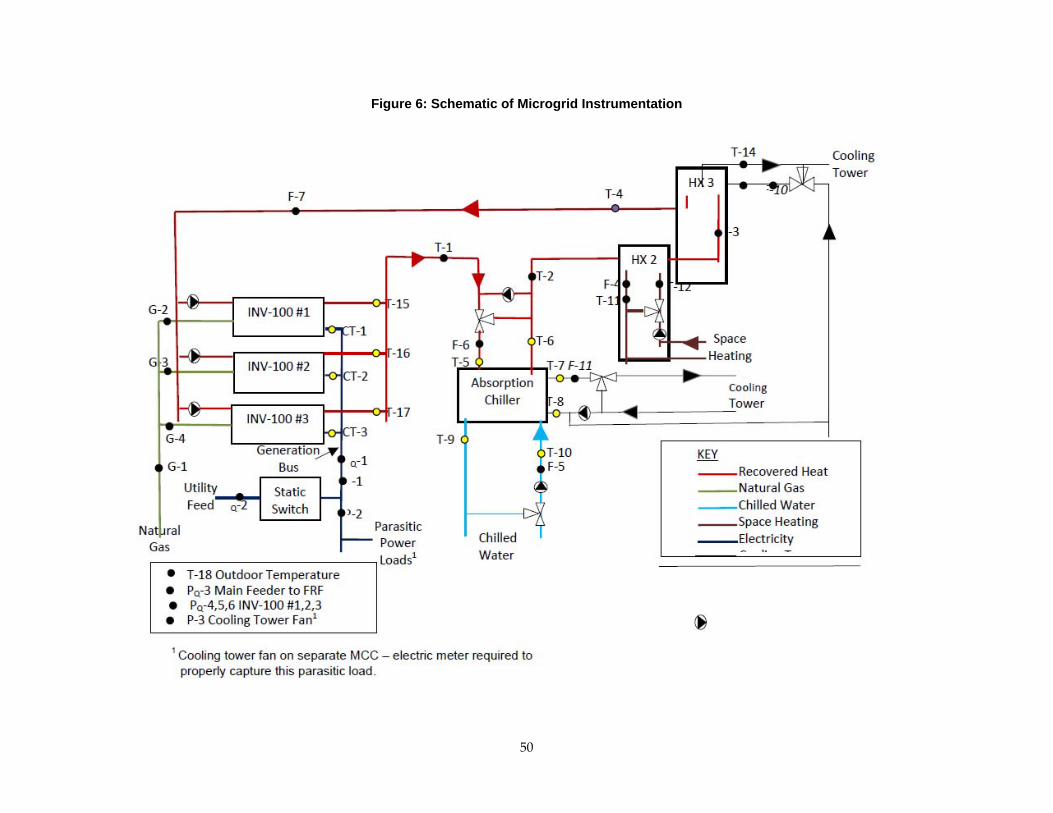
50
Figure 6: Schematic of Microgrid Instrumentation

A‐1
Table 2: Microgrid Instrumentation List
Sensor ID Description Sensor Type Units E/N
T-1 Heat recovery supply temperature RTD – Liquid Immersion °F N T-2 HW temperature to load HX RTD – Liquid Immersion °F E T-3 HW temperature to dump HX RTD – Liquid Immersion °F N T-4 Heat recovery return temperature RTD – Liquid Immersion °F N T-5 HW temperature to absorber RTD – Liquid Immersion °F E T-6 HW temperature out of absorber RTD – Liquid Immersion °F E T-7 CW temp out of absorber RTD – Liquid Immersion °F E T-8 CW temp into absorber RTD – Liquid Immersion °F E T-9 CHW temp out of absorber RTD – Liquid Immersion °F E
T-10 CHW temp into absorber RTD – Liquid Immersion °F E T-11 SH water temp out of load HX RTD – Liquid Immersion °F N T-12 SH water temp into load HX RTD – Liquid Immersion °F N T-13 CW temp into dump HX RTD – Liquid Immersion °F N T-14 CW temp out of dump HX RTD – Liquid Immersion °F N
T-15, 16, 17 HW temp out of INV-1, 2, 3 Thermister °F E T-18 Outdoor temperature RTD – Outside Air °F N F-7 Primary heat recovery loop flow rate Insertion Flow Meter GPM N F-6 HW flow rate through absorber Insertion Flow Meter GPM N F-5 CHW flow rate through absorber Insertion Flow Meter GPM N
F-11 CW flow rate through absorber Insertion Flow Meter GPM N F-4 SH hot water flow rate though load HX Insertion Flow Meter GPM N
F-10 CW flow rate through dump HX Insertion Flow Meter GPM N G-4 PG&E gas meter Gas Flow Meter Scf/min N
G-1, 2, 3 Gas flow rate through each INV-100 Gas Flow Meter Scf/min N P-1 Gross electric power output Electric Meter kWh N P-2 Parasitic electric power demand Electric Meter kWh N P-3 CT fan electric demand Electric Meter kWh N
P-4, 5, 6 Power out of each INV-100 Calculated from CT-1,2,3 kWh E PQ-1 Power quality – Generation Bus Power Quality Meter various N
PQ-2 Power quality – Utility Side of Static Switch Power Quality Meter various N
PQ-3 Power quality – Main Feed to FRF Power Quality Meter various N PQ-4,5,6 Power quality – INV-100 #1,2,3 Power Quality Meter various N
NGHHV Natural gas higher heating value (HHV) Supplied by PG&E Btu/scf
NOx and CO emissions Portable Analyzer ppm N Notes: HW = hot water; CW = cooling water; CHW = chilled water; SH = space heating; HX = heat
exchanger; E = included with equipment; N = new sensor to be procured; RTD = resistance temperature detector; CT-1,2,3 = current transducer reading calculated by the CHP system’s microprocessor and available to the building automation system through Modbus communications protocol via a remote terminal unit (RTU); NOx = nitrogen oxides; CO = carbon monoxide
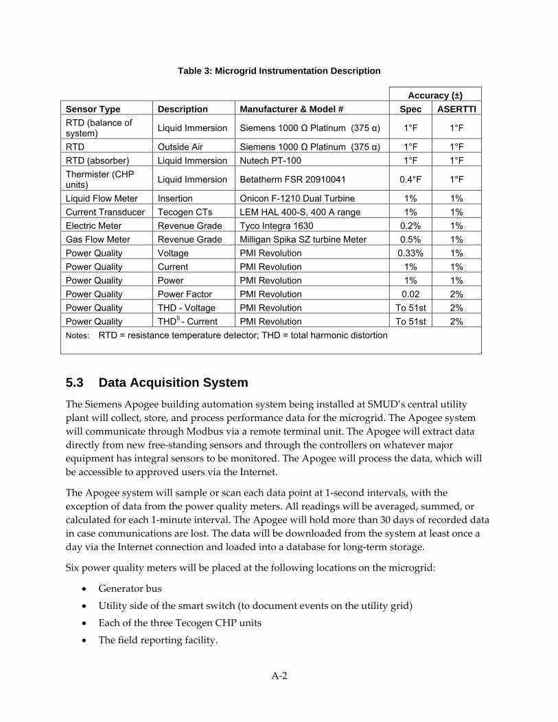
A‐2
Table 3: Microgrid Instrumentation Description
Accuracy (±) Sensor Type Description Manufacturer & Model # Spec ASERTTIRTD (balance of system) Liquid Immersion Siemens 1000 Ω Platinum (375 α) 1°F 1°F
RTD Outside Air Siemens 1000 Ω Platinum (375 α) 1°F 1°F RTD (absorber) Liquid Immersion Nutech PT-100 1°F 1°F Thermister (CHP units) Liquid Immersion Betatherm FSR 20910041 0.4°F 1°F
Liquid Flow Meter Insertion Onicon F-1210 Dual Turbine 1% 1% Current Transducer Tecogen CTs LEM HAL 400-S, 400 A range 1% 1% Electric Meter Revenue Grade Tyco Integra 1630 0.2% 1% Gas Flow Meter Revenue Grade Milligan Spika SZ turbine Meter 0.5% 1% Power Quality Voltage PMI Revolution 0.33% 1% Power Quality Current PMI Revolution 1% 1% Power Quality Power PMI Revolution 1% 1% Power Quality Power Factor PMI Revolution 0.02 2% Power Quality THD - Voltage PMI Revolution To 51st 2% Power Quality THD5 - Current PMI Revolution To 51st 2% Notes: RTD = resistance temperature detector; THD = total harmonic distortion
5.3 Data Acquisition System The Siemens Apogee building automation system being installed at SMUD’s central utility plant will collect, store, and process performance data for the microgrid. The Apogee system will communicate through Modbus via a remote terminal unit. The Apogee will extract data directly from new free‐standing sensors and through the controllers on whatever major equipment has integral sensors to be monitored. The Apogee will process the data, which will be accessible to approved users via the Internet.
The Apogee system will sample or scan each data point at 1‐second intervals, with the exception of data from the power quality meters. All readings will be averaged, summed, or calculated for each 1‐minute interval. The Apogee will hold more than 30 days of recorded data in case communications are lost. The data will be downloaded from the system at least once a day via the Internet connection and loaded into a database for long‐term storage.
Six power quality meters will be placed at the following locations on the microgrid:
• Generator bus
• Utility side of the smart switch (to document events on the utility grid)
• Each of the three Tecogen CHP units
• The field reporting facility.

A‐3
These meters will record the following power quality data every cycle:
• Frequency
• Voltage
• Current
• Power
• Reactive power
• Phase angle
• Power factor
• Harmonics.
The power quality meters will store the data for 10 minutes unless there is a power quality event, in which case the data will be retained and uploaded to the Apogee building automation system. The data will be downloaded from the Apogee system daily and loaded into the database.
A handheld portable emission analyzer will be used to test the exhaust emissions periodically for nitrogen oxides and carbon monoxide. The data will be manually logged into the database.
An operational log will be maintained to track scheduled and unscheduled outages. This information will also be entered into the database.
5.3.1 Data Acquisition System Support Siemens will maintain the Apogee building automation system over the 18‐month monitoring period. SMUD personnel will periodically check to ensure that the system is operating properly. In the event of an issue with the sensors or the data collection process, the appropriate party (Siemens, the equipment supplier, or other) will be contacted to make the repair.
Midway through the 18‐month monitoring period, the instrumentation and sensors will be checked to verify their accuracy. Readings from temperature sensors and power transducers will be compared to readings from handheld instruments. Where feasible, flow readings will be checked using ultrasonic flow meters. A verification summary report will document these measurements and findings.
5.3.2 Data Analysis Values will be calculated in the building automation system at each 1‐minute interval (Table 4). Other interval calculations can be made by averaging the 1‐minute data over the desired interval period (daily, monthly, or annual).
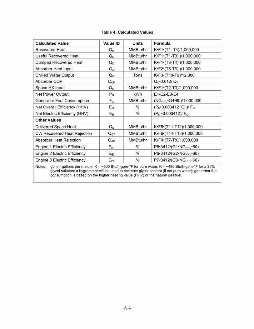
A‐4
Table 4: Calculated Values
Calculated Value Value ID Units Formula Recovered Heat QR MMBtu/hr K•F1•(T1–T4)/1,000,000 Useful Recovered Heat QU MMBtu/hr K•F1•(T1-T3) )/1,000,000 Dumped Recovered Heat QD MMBtu/hr K•F1•(T3-T4) )/1,000,000 Absorber Heat Input QA MMBtu/hr K•F2•(T5-T6) )/1,000,000 Chilled Water Output QC Tons K•F3•(T10-T9)/12,000 Absorber COP COP QC•0.012/ QA Space HX Input QH MMBtu/hr K•F1•(T2-T3)/1,000,000 Net Power Output PN kWh E1-E2-E3-E4 Generator Fuel Consumption FC MMBtu/hr (NGHHV•G4•60)/1,000,000 Net Overall Efficiency (HHV) EO % (PN•0.003412+QU)/ FC Net Electric Efficiency (HHV) EE % (PN •0.003412)/ FC Other Values Delivered Space Heat QS MMBtu/hr K•F5•(T11-T12)/1,000,000 CW Recovered Heat Rejection QCT MMBtu/hr K•F6•(T14-T13)/1,000,000 Absorber Heat Rejection QAC MMBtu/hr K•F4•(T7-T8)/1,000,000 Engine 1 Electric Efficiency EE1 % P5•3412/(G1•NGHHV•60) Engine 2 Electric Efficiency EE2 % P6•3412/(G2•NGHHV•60) Engine 3 Electric Efficiency EE3 % P7•3412/(G3•NGHHV•60) Notes: gpm = gallons per minute; K = ~500 Btu/h-gpm-°F for pure water; K = ~480 Btu/h-gpm-°F for a 30%
glycol solution; a hygrometer will be used to estimate glycol content (if not pure water); generator fuel consumption is based on the higher heating value (HHV) of the natural gas fuel.

A‐5
CHAPTER 6: Demonstration 6.1 Introduction and Goals The goal of this task is to demonstrate the ability of the microgrid to serve sensitive and nonsensitive loads within SMUD’s central utility plant over a 12‐month demonstration period, which has been rescheduled due to delays during construction and startup.
6.2 Operational Test Results Once the microgrid is operating, SMUD will submit quarterly reports that will serve as addendums to this final report. During the demonstration, abnormal events will be investigated and reported. If any corrective actions are needed, these will be reported quarterly as well.
The fourth quarterly report will include not only that quarter’s data, but also a summary of the full year’s data. The fourth report will explain what the data say about the microgrid’s performance in terms of the ASERTTI test protocol for distributed generation and CHP systems. The report will also note any other key takeaways from monitoring the microgrid’s operation and performance during the demonstration.
A‐6
CHAPTER 7: Market Analysis 7.1 Introduction and Goals The goal of this task is to assess whether the microgrid technology being demonstrated can be applied successfully in other utility‐type applications where multiple customers are served by the microgrid. The demonstration project is one example of such an application, where the microgrid serves two buildings at the end of a feeder.
The research team has not yet been able to monitor the operation of the microgrid and record performance data, due to the delays mentioned in Chapters 3 and 6. However, a previous market assessment performed for SMUD can serve as an indicator of the microgrid’s economic and technical potential. The following material (section 7.2) comes from a study by ICF International, Inc., and DE Solutions, Inc. (listed in the Bibliography of this final report).
When the monitoring and operating data from the microgrid demonstration become available, the research team will supplement the study’s information by assessing the market for the type of microgrid being demonstrated in this project (multiple customers in a utility application). This assessment will evaluate the extent to which such microgrids in SMUD’s power system can –
• Address rapidly growing demand.
• Reduce peak loads.
• Improve the utilization of the electricity distribution network.
• Enable demand response.
• Facilitate the inclusion of distributed generation, both renewable and nonrenewable.
7.2 CHP Market Assessment This assessment is based on ICF’s CHP market model, which estimates the cumulative CHP market penetration as a function of –
• Competing CHP system specifications.
• Current and future energy prices.
• The electric and thermal load characteristics in target markets.
The analysis focuses on natural gas‐fueled systems and does not consider CHP powered by renewable resources.
7.2.1 Technical Potential The technical potential of the CHP market is an estimate of the technically suitable CHP applications by size (system capacity) and by industry. This estimate is derived by screening customer data and using the results to identify groups of facilities with the electrical and thermal load characteristics that are conducive to CHP applications.

A‐7
Tables 5 and 6 show estimates of the CHP market’s technical potential in SMUD’s territory through 2030. The estimates are divided into –
1. Technical potential that serves onsite electrical demands at target facilities in the commercial and industrial sectors
2. Additional CHP technical potential that would be available if target customers are allowed to export excess electricity to the utility grid.
Table 5: Growth in Technical Potential Through 2030
Site Size Range
ApplicationType
PotentialMW
50—500 kW
Industrial 2.1 Commercial 34.3 Export 0.9 Subtotal 37.3
500 kW—1 MW
Industrial 1.5 Commercial 5.4 Export 0.2 Subtotal 7.1
1—5 MW
Industrial 0.9 Commercial 18.9 Export 0.2 Subtotal 20.0
5—20 MW
Industrial 6.6 Commercial 15.8 Export 3.5 Subtotal 25.9
all sizes (50 kW—5 MW)
Industrial 11.1 Commercial 74.4 Export 4.9 Total 90.4
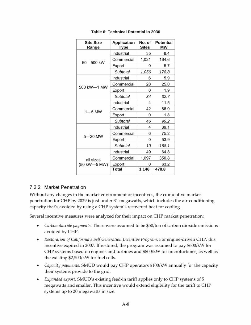
A‐8
Table 6: Technical Potential in 2030
Site Size Range
ApplicationType
No. ofSites
PotentialMW
50—500 kW
Industrial 35 8.4 Commercial 1,021 164.6 Export 0 5.7 Subtotal 1,056 178.8
500 kW—1 MW
Industrial 6 5.9 Commercial 28 25.0 Export 0 1.9 Subtotal 34 32.7
1—5 MW
Industrial 4 11.5 Commercial 42 86.0 Export 0 1.8 Subtotal 46 99.2
5—20 MW
Industrial 4 39.1 Commercial 6 75.2 Export 0 53.9 Subtotal 10 168.1
all sizes (50 kW—5 MW)
Industrial 49 64.8 Commercial 1,097 350.8 Export 0 63.2 Total 1,146 478.8
7.2.2 Market Penetration Without any changes in the market environment or incentives, the cumulative market penetration for CHP by 2029 is just under 31 megawatts, which includes the air‐conditioning capacity that’s avoided by using a CHP system’s recovered heat for cooling.
Several incentive measures were analyzed for their impact on CHP market penetration:
• Carbon dioxide payments. These were assumed to be $50/ton of carbon dioxide emissions avoided by CHP.
• Restoration of California’s Self Generation Incentive Program. For engine‐driven CHP, this incentive expired in 2007. If restored, the program was assumed to pay $600/kW for CHP systems based on engines and turbines and $800/kW for microturbines, as well as the existing $2,500/kW for fuel cells.
• Capacity payments. SMUD would pay CHP operators $100/kW annually for the capacity their systems provide to the grid.
• Expanded export. SMUD’s existing feed‐in tariff applies only to CHP systems of 5 megawatts and smaller. This incentive would extend eligibility for the tariff to CHP systems up to 20 megawatts in size.
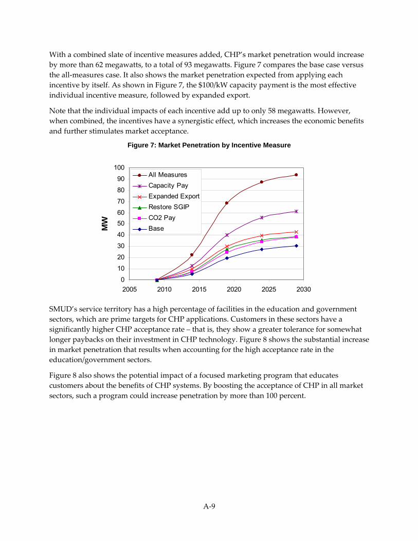
A‐9
With a combined slate of incentive measures added, CHP’s market penetration would increase by more than 62 megawatts, to a total of 93 megawatts. Figure 7 compares the base case versus the all‐measures case. It also shows the market penetration expected from applying each incentive by itself. As shown in Figure 7, the $100/kW capacity payment is the most effective individual incentive measure, followed by expanded export.
Note that the individual impacts of each incentive add up to only 58 megawatts. However, when combined, the incentives have a synergistic effect, which increases the economic benefits and further stimulates market acceptance.
Figure 7: Market Penetration by Incentive Measure
0
10
20
30
40
5060
70
80
90
100
2005 2010 2015 2020 2025 2030
MW
All MeasuresCapacity PayExpanded ExportRestore SGIPCO2 PayBase
SMUD’s service territory has a high percentage of facilities in the education and government sectors, which are prime targets for CHP applications. Customers in these sectors have a significantly higher CHP acceptance rate – that is, they show a greater tolerance for somewhat longer paybacks on their investment in CHP technology. Figure 8 shows the substantial increase in market penetration that results when accounting for the high acceptance rate in the education/government sectors.
Figure 8 also shows the potential impact of a focused marketing program that educates customers about the benefits of CHP systems. By boosting the acceptance of CHP in all market sectors, such a program could increase penetration by more than 100 percent.

A‐10
Figure 8: Comparison of Scenarios with Revised Market Acceptance Rates
0
50
100
150
200
250
2009 2014 2019 2024 2029
MW
All-In - High All MarketsAll-In - High Edu/GovAll-In - OrigBase - High All MarketsBase - High Edu/GovBase - Orig

A‐11
CHAPTER 8: Technology Transfer The goal of this task is to develop a plan to transfer the microgrid technology to key decision‐makers and the general public by making the following information available:
• The knowledge gained throughout the project.
• The experimental results from operating and monitoring the microgrid.
• The lessons learned from the microgrid demonstration experience.
Technology transfer will be initiated when the microgrid’s operational results become available. Until then, as a key part of the technology transfer plan, the project team will participate in the annual Microgrid Research Symposium, which was established by PIER in 2005. The symposium brings together microgrid researchers and utilities to discuss current findings on internationally funded research around the world.

A‐12
GLOSSARY
Acronym/ Abbreviation Meaning
AC alternating current ANSI American National Standards Institute ASERTTI Association of State Energy Research and Technology Transfer InstitutionsASHRAE American Society of Heating, Refrigerating, and Air-Conditioning EngineersBtu British thermal unit Btu/h Btu per hour CBEMA Computer and Business Equipment Manufacturers Association CERTS Consortium for Electric Reliability Technology Solutions DC direct current g/bhp-hr grams per brake-horsepower per hour HVAC heating, ventilation, and air-conditioning HVAC&R heating, ventilation, air-conditioning, and refrigeration ITIC International Technology Industry Council kV kilovolt kVA kilovolt-amp kW kilowatt kW/ton kilowatts per ton lb/MWh pounds per megawatt-hour MWh megawatt-hour O&M operating/operation and maintenance PIER Public Interest Energy Research PV photovoltaics RD&D research, development, and demonstration rpm revolutions/rotations per minute SMUD Sacramento Municipal Utility District UL Underwriters Laboratories
A‐13
REFERENCES
Agrawal, P., Rawson, M., Blazewicz, S., and Small, F. “How ‘Microgrids’ Are Poised to Alter the Power Delivery Landscape.” Utility Automation & Engineering T&D. Vol. 11, No. 6. July/August 2006.
Feero, W. E., Dawson, D. C., and Stevens, J. Protection Issues of the MicroGrid Concept. Lawrence Berkeley National Laboratory. March 2002
Firestone, R., and Marnay, C. Energy Manager Design for Microgrids. Lawrence Berkeley National Laboratory, Report No. LBNL‐54447. January 2005.
ICF International, Inc., and DE Solutions, Inc. Combined Heat and Power Market Assessment for Sacramento Municipal Utility District. November 2009.
Nichols, D., et al. Validation of the CERTS Microgrid Concept: The CEC/CERTS Microgrid Testbed. Paper presented at the IEEE Power Engineering Society General Meeting. June 18‐22, 2006.
Piagi, P., and Lasseter, R. H. Autonomous Control of Microgrids. University of Wisconsin‐Madison. June 2006.
Lasseter, R. H. Dynamic Distribution using (DER) Distributed Energy Resources. University of Wisconsin‐Madison. May 2006.
Lasseter, R. H., and Piagi, P. Control and Design of Microgrid Components. University of Wisconsin‐Madison. January 2006
Lasseter, R. H., et al. Integration of Distributed Energy Resources: The CERTS MicroGrid Concept. Lawrence Berkeley National Laboratory, White Paper No. LBNL‐50829. April 2002.
Lasseter, R. H., et al. CERTS Microgrid Laboratory Test Bed. IEEE Transactions on Power Delivery. Vol. 26, No. 1. January 2011.
Marnay, C., and Bailey, O. The CERTS Microgrid and the Future of the Macrogrid. Lawrence Berkeley National Laboratory, Report No. LBNL‐55281. August 2004.


