Method of beam extraction from a synchrotron by the instrumentality of
multilayer Cu-Fe shield
Bondarenko Alexey
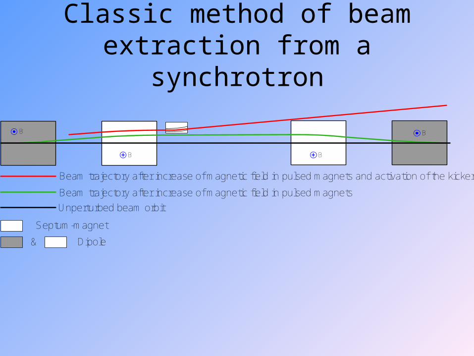
Classic method of beam extraction from a synchrotron
Beam trajectory after increase of magnetic field in pulsed magnets and activation of the kicker
Beam trajectory after increase of magnetic field in pulsed magnets
Unperturbed beam orbit
Septum-magnet
Dipole&
B B
B B
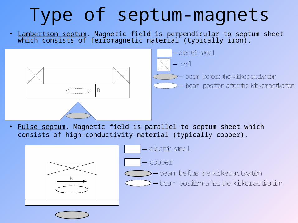
Type of septum-magnets• Lambertson septum. Magnetic field is perpendicular to septum sheet
which consists of ferromagnetic material (typically iron).
• Pulse septum. Magnetic field is parallel to septum sheet which consists of high-conductivity material (typically copper).
beam before the kicker activation
copper
beam position after the kicker activation
electric steel
B
beam before the kicker activation
electric steel
beam position after the kicker activationB
coil
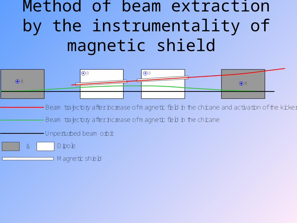
Method of beam extraction by the instrumentality of magnetic shield
Beam trajectory after increase of magnetic field in the chicane and activation of the kicker
Beam trajectory after increase of magnetic field in the chicane
Unperturbed beam orbit
Dipole&
Magnetic shield
B B
B B
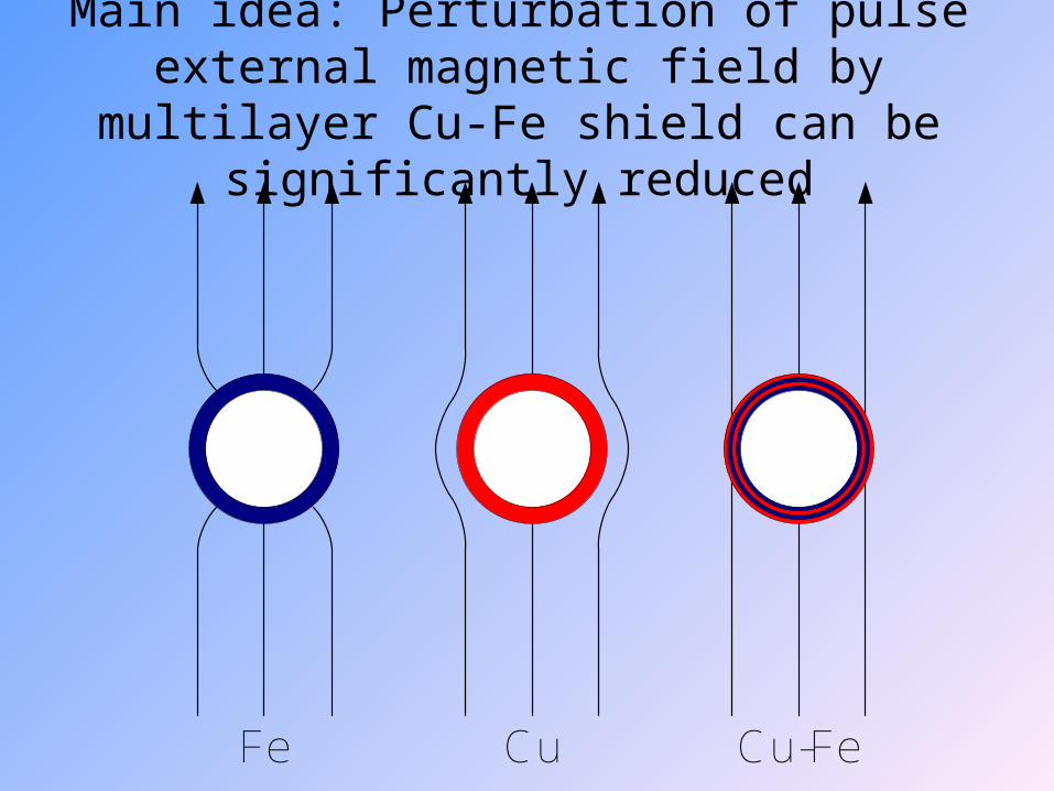
Main idea: Perturbation of pulse external magnetic field by multilayer Cu-Fe shield can
be significantly reduced
Fe Cu Cu-Fe
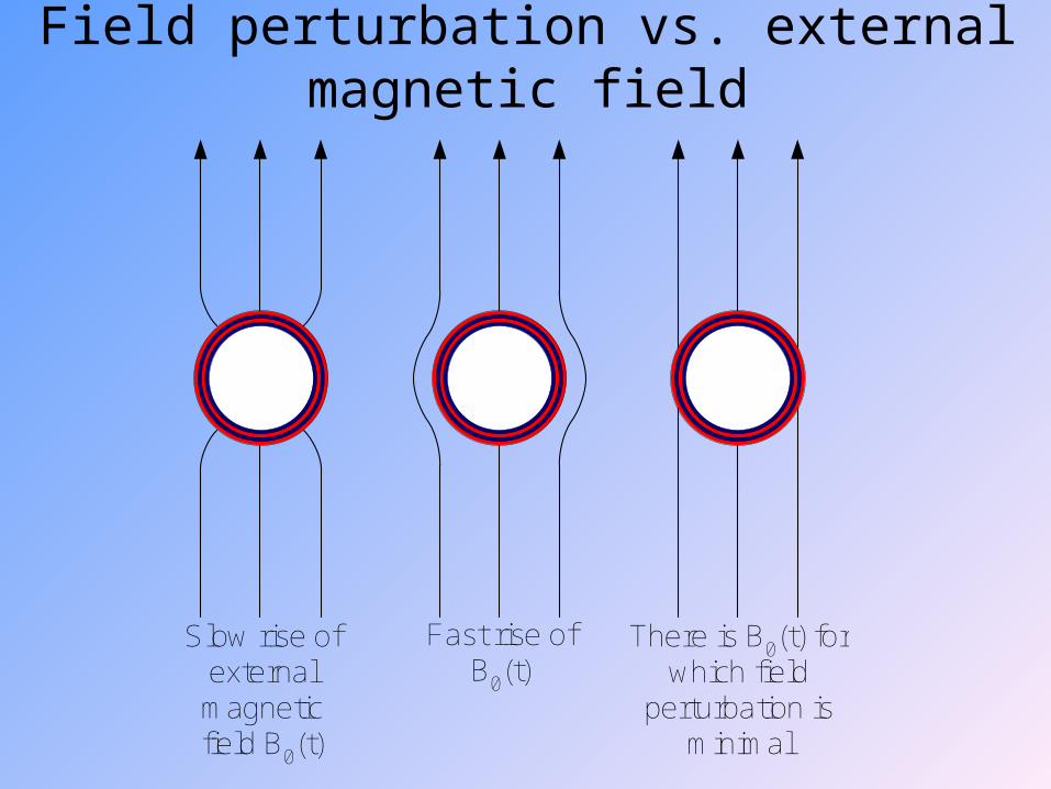
Field perturbation vs. external magnetic field
Slow rise ofexternalmagneticfield B0(t)
There is B0(t) forwhich field
perturbation isminimal
Fast rise ofB0(t)
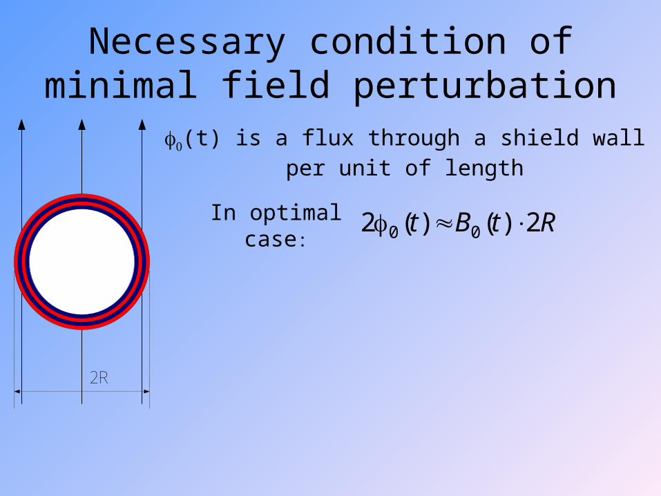
Necessary condition of minimal field perturbation
2R
In optimal case:
(t) is a flux through a shield wall per unit of length
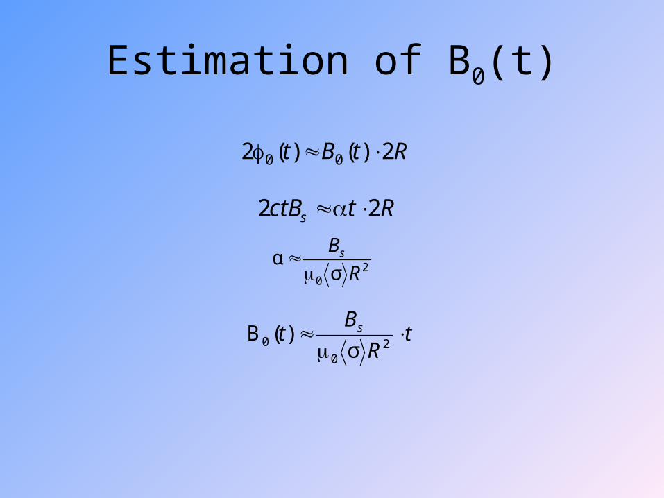
RtBt 2)()(2 00
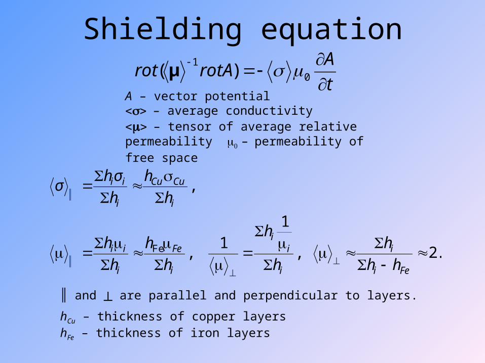
Shielding equation
t
ArotArot
0
1)( μ
.2,
11
,
,
Fe
Fei
i
i
ii
i
Fe
i
ii
i
CuCu
i
ii
hh
h
h
h
h
h
h
h
h
h
h
σhσ
A – vector potential– average conductivity– tensor of average relative permeability –permeability of free space
║ and ┴ are parallel and perpendicular to layers.
hCu – thickness of copper layershFe – thickness of iron layers
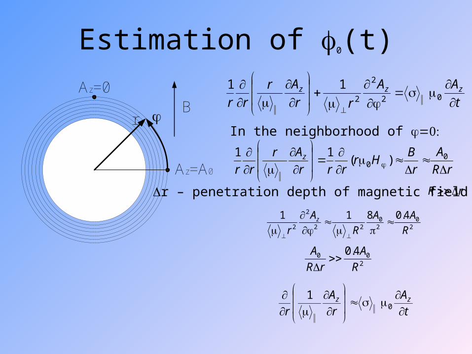
Estimation of 0(t)
t
AA
rr
Ar
rrzzz
02
2
2
11
20
20
22
2
2
4.0811
R
AA
R
A
rz
200 4.0
R
A
rR
A
In the neighborhood of
t
A
r
A
rzz
01
rR
rR
A
r
BHr
rrr
Ar
rrz
0
0 )(11
r – penetration depth of magnetic field
r
Az=A0
Az=0B
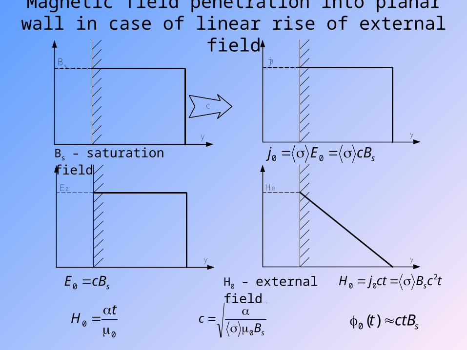
Magnetic field penetration into planar wall in case of linear rise of external field
E0
y
j0
y
H0
y
Bs – saturation field
Bs
y
c
scBE 0
00
tH
H0 – external field
scBEj 00
tcBctjH s2
00
sBc
0
sctBt )(0
tR
Bt s
20
0 σ)(B
RtBt 2)()(2 00
RtctBs 22
20 σ
αR
Bs
Estimation of B0(t)
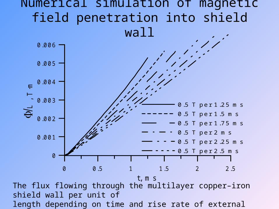
Numerical simulation of magnetic field penetration into shield wall
The flux flowing through the multilayer copper–iron shield wall per unit oflength depending on time and rise rate of external magnetic field.
0 0.5 1 1.5 2 2.5t, m s
0
0.001
0.002
0.003
0.004
0.005
0.006
L
, T
·m
0.5 T per 1 .25 m s0.5 T per 1 .5 m s0.5 T per 1 .75 m s0.5 T per 2 m s0.5 T per 2 .25 m s0.5 T per 2 .5 m s
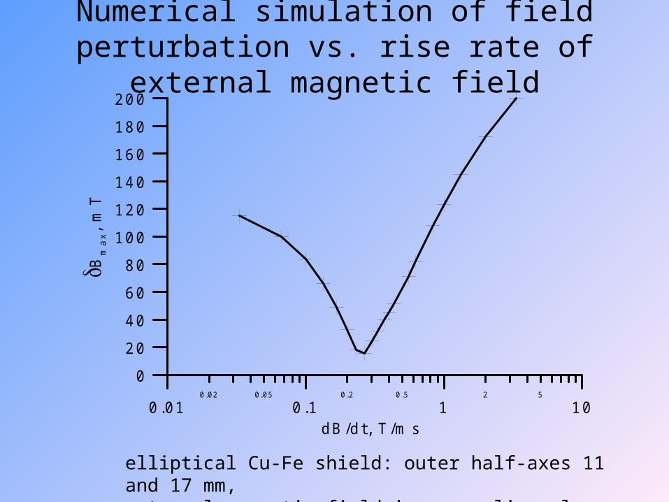
Numerical simulation of field perturbation vs. rise rate of external magnetic field
0.01 0.1 1 100.02 0.05 0.2 0.5 2 5
dB/dt, T /m s
0
20
40
60
80
100
120
140
160
180
200B
ma
x, m
T
elliptical Cu-Fe shield: outer half-axes 11 and 17 mm, external magnetic field increase linearly from 0 to 0.5 T
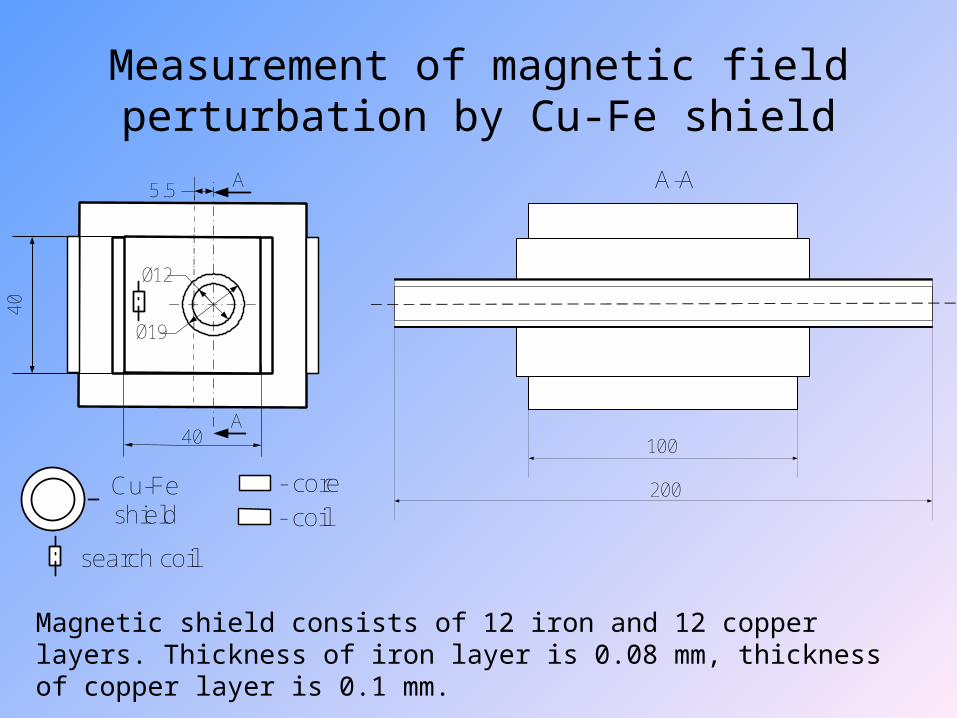
Measurement of magnetic field perturbation by Cu-Fe shield
Magnetic shield consists of 12 iron and 12 copper layers. Thickness of iron layer is 0.08 mm, thickness of copper layer is 0.1 mm.
5.5
Ø12
Ø19
40
40
Cu-Feshield
- core
- coil
A
A
A-A
100
200
search coil
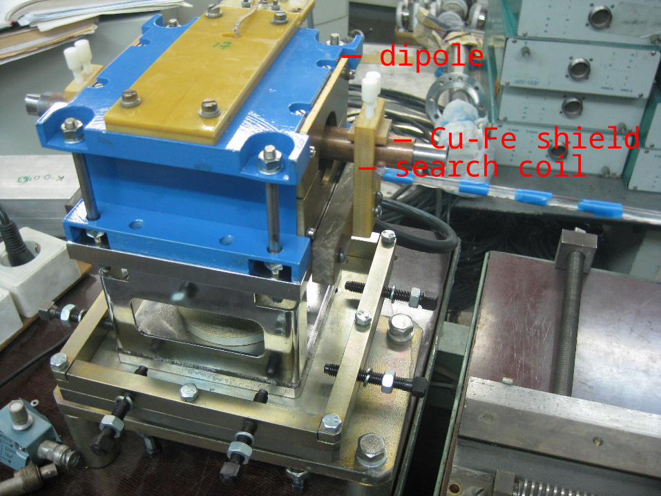
— search coil— Cu-Fe shield
— dipole
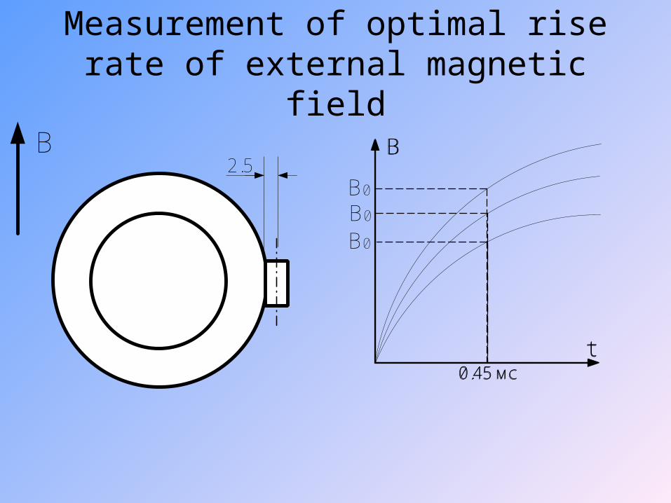
Measurement of optimal rise rate of external magnetic field
2.5
B0
0.45 мс
B
t
B
B0
0.45 мс
B
t
B0
0.45 мс
B
t

Maximum of magnetic field perturbation vs. rise rate of external magnetic field
0 0.02 0.04 0.06 0.08 0.1 0.12B 0 , T
0
1
2
3
4
5
6
Bm
ax, m
T
B0 – field at 0.45 ms since the dipole is activated .
Optimal rise rate of external magnetic field is 0.108 T per 0.45 ms
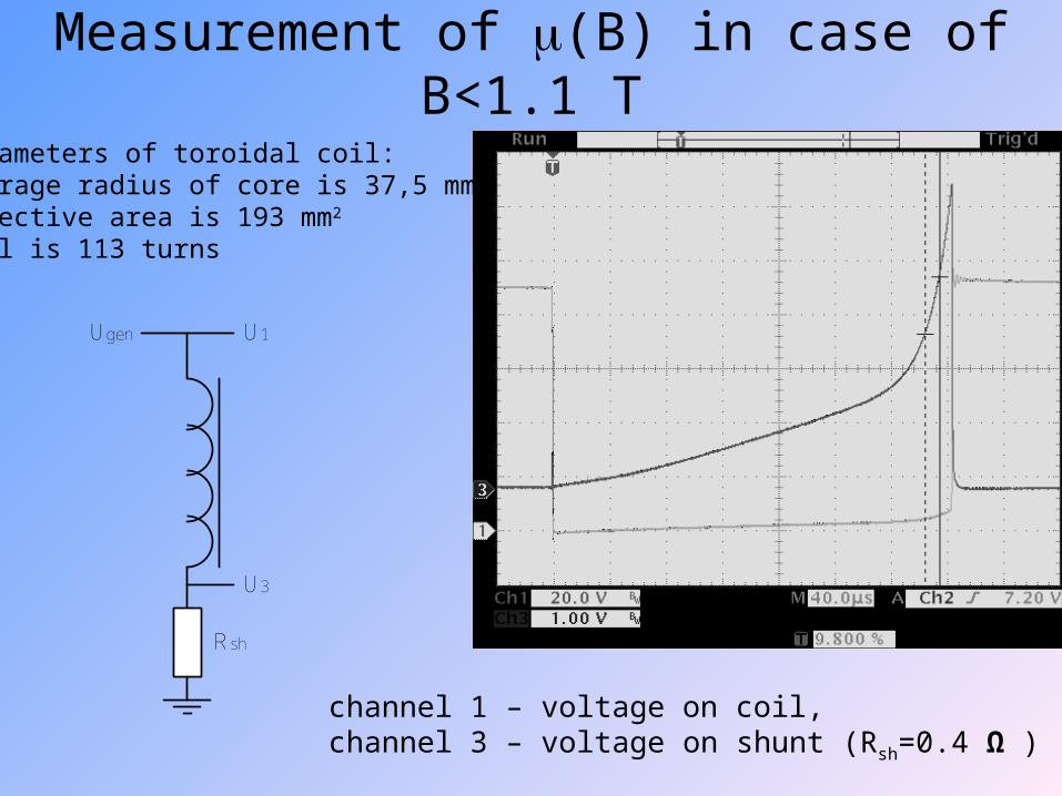
Measurement of (B) in case of B<1.1 Т
channel 1 – voltage on coil, channel 3 – voltage on shunt (Rsh=0.4 Ω )
Parameters of toroidal coil:Average radius of core is 37,5 mmEffective area is 193 mm2
Coil is 113 turns
Ugen U1
U3
Rsh
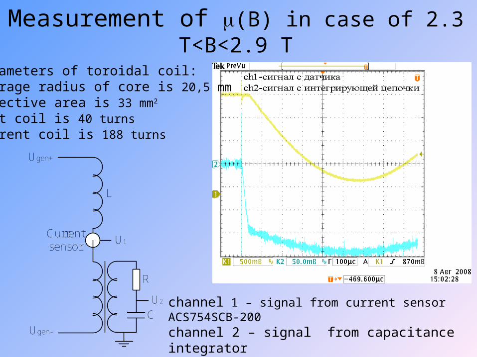
Measurement of (B) in case of 2.3 T<B<2.9 T
channel 1 – signal from current sensor ACS754SCB-200channel 2 – signal from capacitance integrator(R=102.8 kΩ , С=0.195 µF )
Parameters of toroidal coil:Average radius of core is 20,5 mmEffective area is 33 mm2
Test coil is 40 turnsCurrent coil is 188 turns
L
Currentsensor
R
C
U1
U2
Ugen+
Ugen-
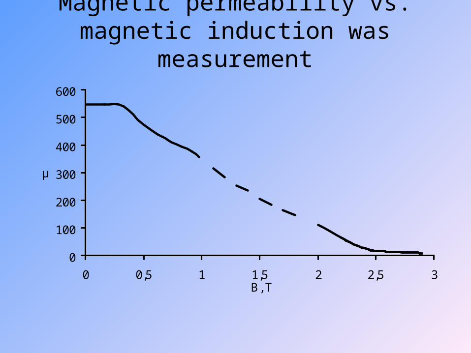
Magnetic permeability vs. magnetic induction was measurement
0
100
200
300
400
500
600
0 0,5 1 1,5 2 2,5 3B, T
μ
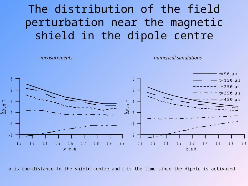
The distribution of the field perturbation near the magnetic shield in the dipole centre
x is the distance to the shield centre and t is the time since the dipole is activated
1 2 1 3 1 4 1 5 1 6 1 7 1 8 1 9 2 0x , m m
- 2
- 1
0
1
2
3
B, m
T
measurements numerical simulations
1 2 1 3 1 4 1 5 1 6 1 7 1 8 1 9 2 0x , m m
- 2
- 1
0
1
2
3
B, m
T
t= 5 0 µ st= 1 5 0 µ st= 2 5 0 µ st= 3 5 0 µ st= 4 5 0 µ s
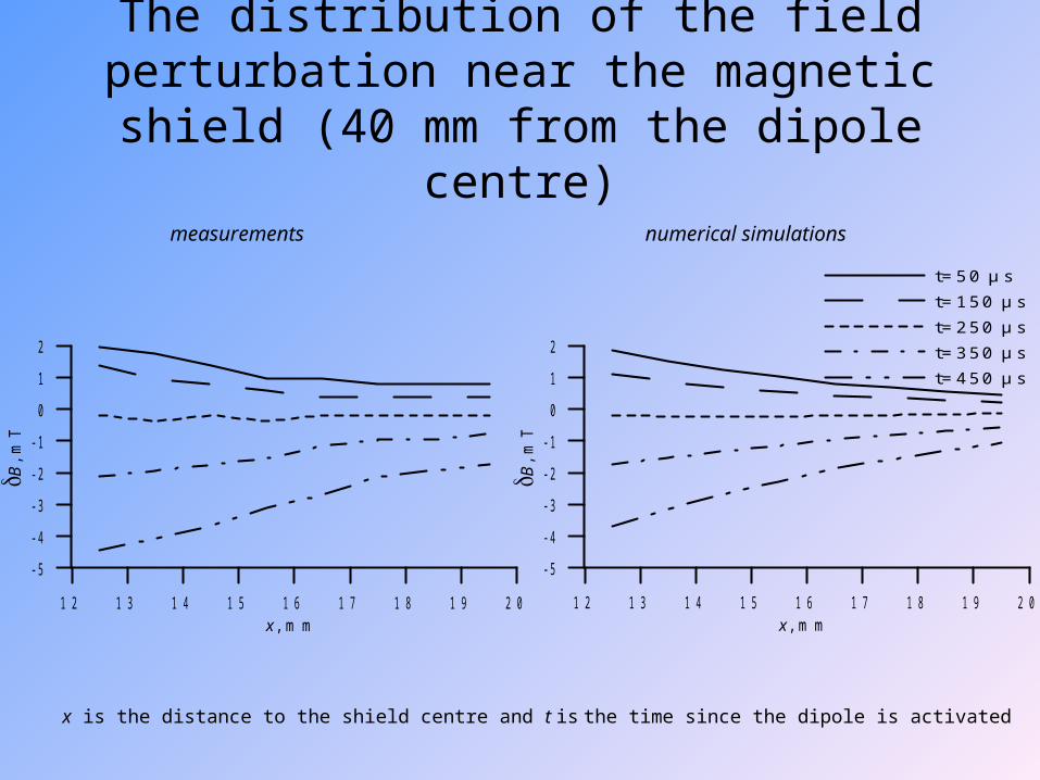
The distribution of the field perturbation near the magnetic shield (40 mm from the dipole centre)
x is the distance to the shield centre and t is the time since the dipole is activated
1 2 1 3 1 4 1 5 1 6 1 7 1 8 1 9 2 0x , m m
- 5
- 4
- 3
- 2
- 1
0
1
2
B, m
T
1 2 1 3 1 4 1 5 1 6 1 7 1 8 1 9 2 0x , m m
- 5
- 4
- 3
- 2
- 1
0
1
2
B, m
T
t= 5 0 µ st= 1 5 0 µ st= 2 5 0 µ st= 3 5 0 µ st= 4 5 0 µ s
measurements numerical simulations

The distribution of the field perturbation near the magnetic shield (55 mm from the dipole centre)
x is the distance to the shield centre and t is the time since the dipole is activated
1 2 1 3 1 4 1 5 1 6 1 7 1 8 1 9 2 0x , m m
- 6- 5- 4- 3- 2- 1
012
B, m
T
1 2 1 3 1 4 1 5 1 6 1 7 1 8 1 9 2 0x , m m
- 6- 5- 4- 3- 2- 1
012
B, m
T
t= 5 0 µ st= 1 5 0 µ st= 2 5 0 µ st= 3 5 0 µ st= 4 5 0 µ s
measurements numerical simulations
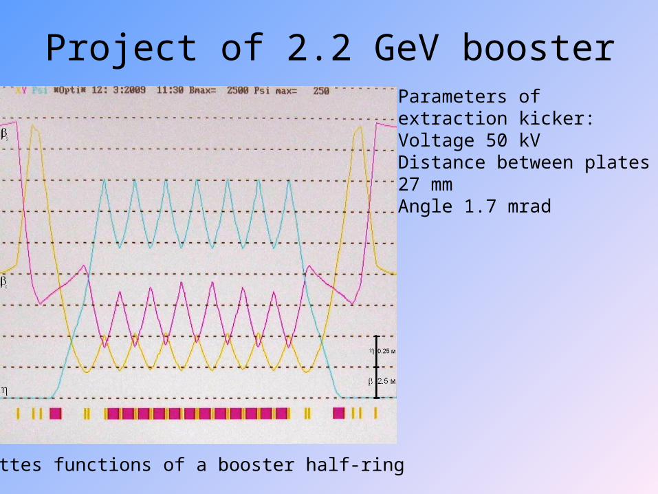
Project of 2.2 GeV booster
Lattes functions of a booster half-ring
Parameters of extraction kicker:Voltage 50 kVDistance between plates 27 mmAngle 1.7 mrad
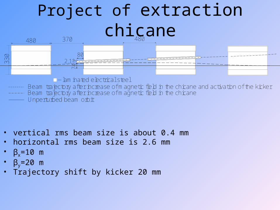
Project of extraction chicane
• vertical rms beam size is about 0.4 mm• horizontal rms beam size is 2.6 mm• βx=10 m• βy=20 m• Trajectory shift by kicker 20 mm
2.1°80
74
480
33
0
370
laminated electrical steel
Beam trajectory after increase of magnetic field in the chicaneUnperturbed beam orbit
Beam trajectory after increase of magnetic field in the chicane and activation of the kicker
480

Field perturbation by Cu-Fe shield
electrical steelcopper
12 20
24
32
ms
tTB
5.145.0
y - the distance to the shield centre B – field perturbation
1 0 1 5 2 0 2 5 3 0 3 5 4 0y , m m
0
5
10
15
20
B, m
T t= 0 .3 m st= 0 .6 m st= 0 .9 m st= 1 .2 m st= 1 .5 m s

K0
0 0.3 0.6 0.9 1.2 1.5t, m s
-0 .1
0
0.1
0.2
0.3
K0,
mra
d
213.072
20103.02
y22
30
1 mm
marctg
Karctg
K0 leads to orbit shift
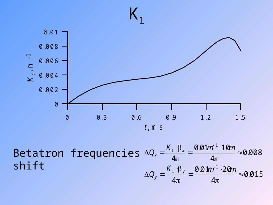
K1
0 0.3 0.6 0.9 1.2 1.5t, m s
0
0.002
0.004
0.006
0.008
0.01K1,
m-1
015.04
2001.0
4
008.04
1001.0
41
1
11
mmKQ
mmKQ
yy
xxBetatron frequencies shift
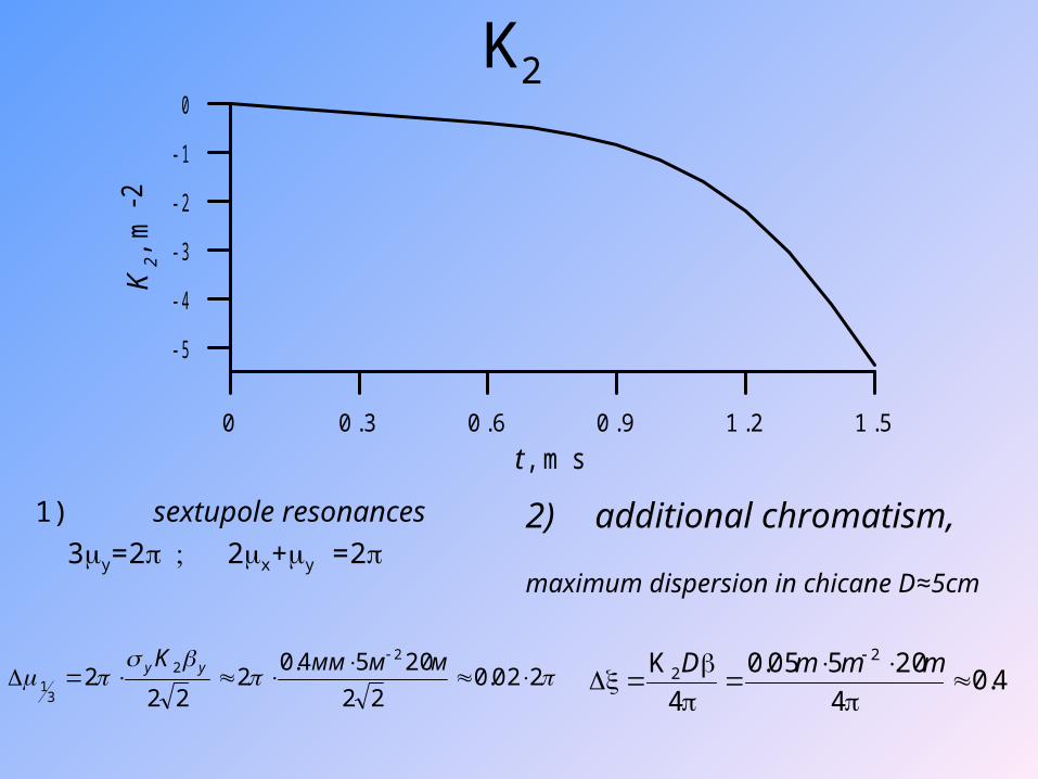
K2
0 0.3 0.6 0.9 1.2 1.5t , m s
- 5
- 4
- 3
- 2
- 1
0K2,
m-2
202.022
2054.02
222
22
31
ммммK yy
1) sextupole resonances
3y=22x+y =22) additional chromatism,
maximum dispersion in chicane D≈5cm
4.04
20505.0
4
K 22
mmmD
Field perturbation by vacuum chambers
Time of field rise is 1.5 ms. In case of cylindrical vacuum chamber field perturbation is minimal because:
• Walls of cylindrical vacuum chamber can be made thinner.
• Field perturbation in cylindrical vacuum chamber by homogenous magnetic field is homogenous. Higher multipoles are results of image the vacuum chamber in magnet gap.

Comparison with other extraction system from booster
HIGS Booster in Duke University, 1.2 GeV, vertical extraction, Lambertson septum
K0 K1 K2
0 0.02 m-1 4 m-2
Booster of SPEAR Storage Ring in Stanford Synchrotron Radiation
Laboratory, 3.5 GeV, horizontal extraction, pulse Lambertson septum.
K0 K1 K2
0.2 mrad 0.005 m-1 ?
Project of extraction system 2.2 GeV.
K0 K1 K2
0.3 mrad 0.01 m-1 5 m-2
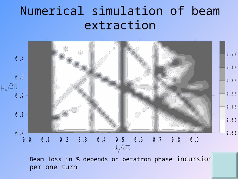
Numerical simulation of beam extraction
Beam loss in % depends on betatron phase incursion per one turn
μy/2π
μx/2π
0.0 0.1 0.2 0.3 0.4 0.5 0.6 0.7 0.8 0.90.0
0.1
0.2
0.3
0.4
0.00
0.05
0.10
0.20
0.30
0.40
0.50
Conclusion
• It was shown that in case of external magnetic field linear rise the rate of magnetic flux penetration into multilayer copper-iron shield wall is constant. This effect can be used for minimization of magnetic field perturbation by multilayer copper-iron shield.
• The prototype of multilayer copper-iron shield was made. Measurement and numerical simulation of magnetic field perturbation by shield were performed. The measurement confirms correctness of method and model which are used for simulation of field perturbation.
• The numerical simulation and analytical estimation of beam dynamics under the influence of field perturbation by multi-layer Cu-Fe shield prove possibility of using the magnetic shield for extraction from synchrotron.
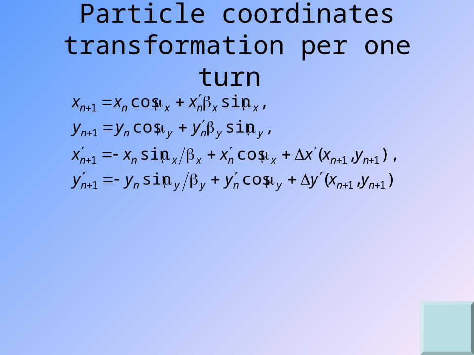
Particle coordinates transformation per one turn
),,(cossin
),,(cossin
,sincos
,sincos
111
111
1
1
nnynyynn
nnxnxxnn
yynynn
xxnxnn
yxyyyy
yxxxxx
yyy
xxx
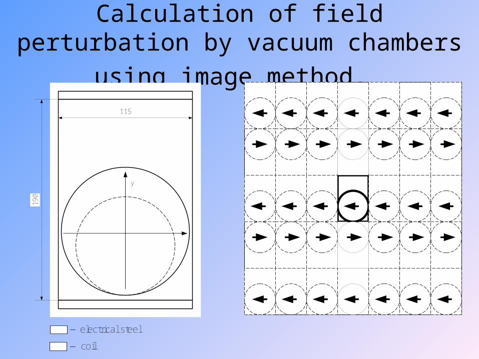
Calculation of field perturbation by vacuum
chambers using image method.
electrical steel
coil
190
115
y
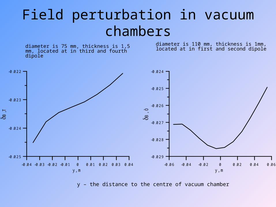
Field perturbation in vacuum chambers
y – the distance to the centre of vacuum chamber
diameter is 110 mm, thickness is 1mm, located at in first and second dipole
diameter is 75 mm, thickness is 1,5 mm, located at in third and fourth dipole
-0 .06 -0.04 -0.02 0 0.02 0.04 0.06y , m
-0 .029
-0.028
-0.027
-0.026
-0.025
-0.024
B, Ò
-0 .04 -0.03 -0.02 -0.01 0 0.01 0.02 0.03 0.04y , m
-0 .025
-0.024
-0.023
-0.022
B,T
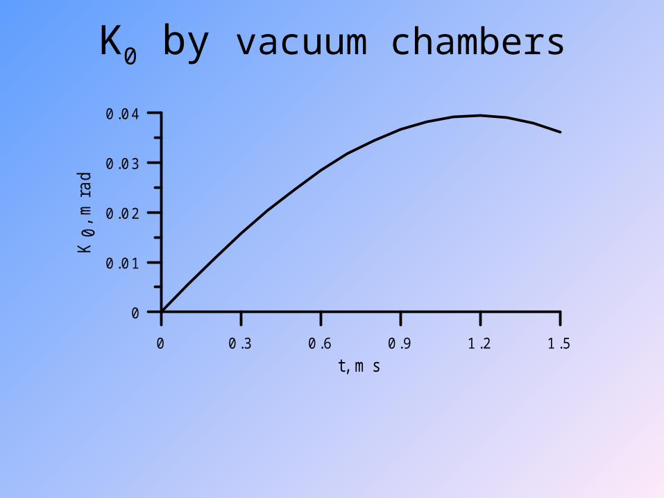
K0 by vacuum chambers
0 0.3 0.6 0.9 1.2 1.5t, m s
0
0.01
0.02
0.03
0.04
K0,
mra
d
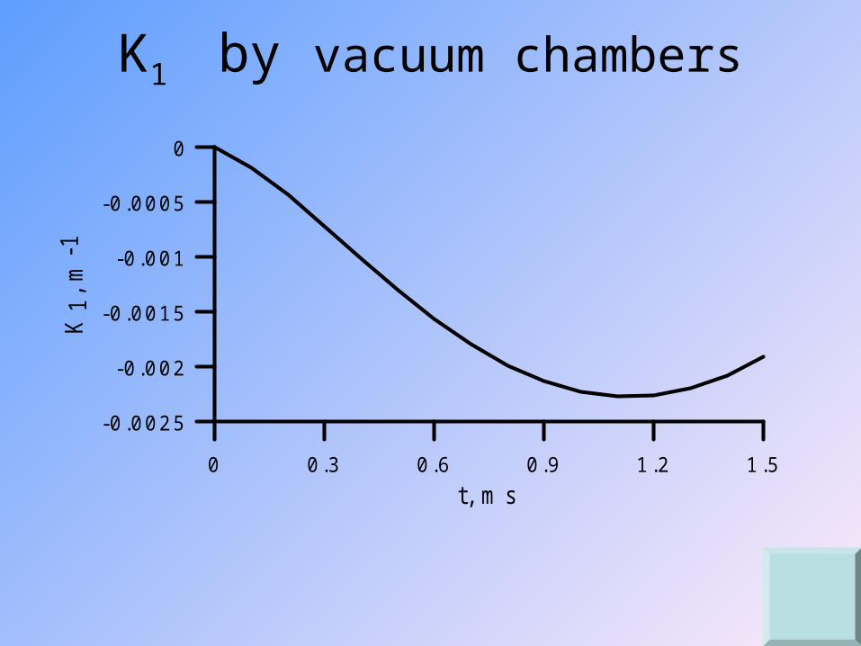
K1 by vacuum chambers
0 0.3 0.6 0.9 1.2 1.5t, m s
-0 .0025
-0.002
-0.0015
-0.001
-0.0005
0
K1,
m-1


