
95
MEASURING PROBES, DIGITAL DISPLAYS AND BENCH TABLES
The Sylvac linear probes are based on the capacitive principle characterized by a high degree of accuracy also on long measuring ranges up to 50mm. The probes are used as measuring elements to be placed on tables, supports, bench tables, special mechanical devices or multi-gauging fixtures.
The probe signal is processed in a display unit. Sylvac offers several of them.Benefiting from the high degree of accuracy of its probes and with the aim to measure small machined parts typically used in watches, Sylvac developed a whole series of benches and tables. These supports are conceived for the control of internal, external, heights, grooves etc, starting from a few tenths to 70mm.
Absolute capacitive measuring system
Digital display units RS232 and USB
Operational temperature 0 to +50°C

96
P2B
P5
P10
P25
Measuring probes
DESCRIPTION
Clamping stem Ø 8-h6
Interchangeable cablesup to 15 m (standard 1.5 m)
P2 and P5: clamping stem Ø 8-h6Measuring anvilInterchangeable contact point M2.5, stainless steel with TC ball
Fixed cable (standard 1.5 m)
97
15.7
5
Ø h68
71.4
45.7
23.2
P2B
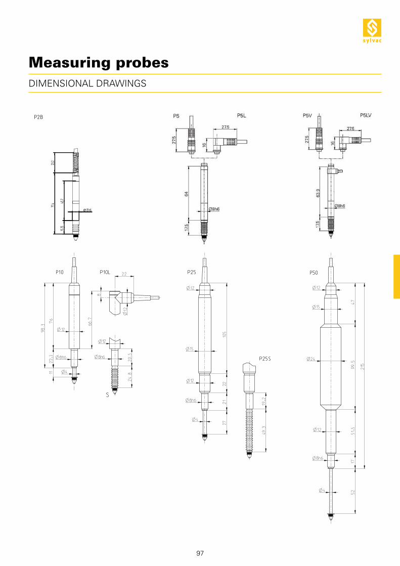
Measuring probes
DIMENSIONAL DRAWINGS

98
90
0.1
001 P
5
90
0.1
003 P
5V
90
0.1
006 P
5L
90
0.1
012 P
10S
90
0.1
014 P
10L
90
0.1
025 P
25
90
0.1
027 P
25S
90
0.1
050 P
50
90
0.1
008 P
5V
L
90
0.1
010 P
10
90
0.1
016 P
10LS
64 64 64 64 64 40 50 40 50 40 50 40
80
0.0
994 P
2B
LISTING OF ALL MODELS
RANGE
2 mm
5 mm
10 mm
25 mm
50 mm
EXECUTION
Plain bearing
B- Ball bearing
V- Vacuum lifter
L- 90 degrees cable
S- with rubber boot
MECHANIC
Diameter 8 mm h6
Diameter 12 mm
Measuring anvil M2.5
LIFTING
Integrated
Separate accessories
PROTECTION IP
Protection rating IP (IEC 60529)
Measuring probes

99
P2B
0.25
0.8
0.2
3.4
P5
0.7
1
0.2
3.7
P10
0.5
1
0.2
4.1
P25
0.8
1.2
0.2
9.6
P50
1
2.5
0.4
15.3
P2B
0.60-0.75
---
---
---
0.70
P5
0.60-1.20
---
0.20-0.25
1.00-1.80
0.70
P10
0.60-0.80
< 0.10
0.20-0.25
0.70-1.50
0.60
P10S
0.70-1.25
---
---
---
---
P25
0.60-1.00
< 0.15
0.20-0.30
0.70-1.60
0.30
P25S
0.65-1.4
---
---
---
---
P50
0.70 - 1.7
---
---
---
0.25
1) with master unit
TECHNICAL SPECIFICATIONS
MEASURING FORCE
Pre-travel mm
Max. Error 1) µm
Repeatability µm
Moving mass g
Standard N
Minimum N
Low N
High N
Lateral max N
Tolerance ± 20%, measuring probe in vertical position, outgoing spindle.
BASIC INSTRUMENT
Probe according to technical specifications
Calibration certificate
Cable 1.5 m
Stainless steel contact point with tungsten carbide ball Ø 2 mm (905.2204)
Measuring probes

100
APPLICATIONS
P5 probes connected to a D50S unit measuring the external diameter of a shaft
P25 probe connected to a D80S unit measuring the height of a part
Combined probes for the measurement of several heights
Measuring probes

905.2204
901.2003
901.2004
901.2005
901.2006
901.2010
901.2011
901.2012
901.2013
901.2014
101
P50P25P10P5P2
ACCESSORIES
Stainless steel contact point M2.5
with TC ball probe (other contact
points, see page 50)
Rubber boot and contact point set
Rubber boot and contact point set
Lifting device with photo-cable
Lifting device with photo-cable
Pneumatic lifting device
Pneumatic lifting device
Tube Ø 4 mm / 2 mm, Length to be
specified
Tube Ø 6 mm / 4 mm, Length to be
specified
Double tube diameter 2 x 4 mm /2 mm,
Length to be specified
Measuring probes
102
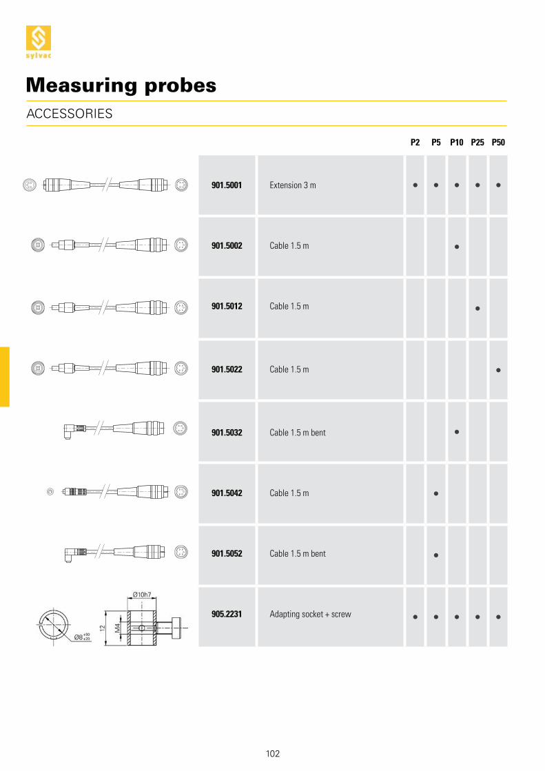
P50P25P10P5P2
ACCESSORIES
Extension 3 m
Cable 1.5 m
Cable 1.5 m
Cable 1.5 m
Cable 1.5 m bent
Cable 1.5 m
Cable 1.5 m bent
Adapting socket + screw
901.5001
901.5002
901.5012
901.5022
901.5032
901.5042
901.5052
905.2231
Measuring probes

2 2 1 1 8 2 (4) 2 2
1 / - 1 / 6
1 1 1 1 1 2 1 1
81) 242) 643)
644)
15)
5)
*) *)
103
D50
S
D50
S P
RO
D60
S P
RO
D80
S
D20
0S
D30
0S *)
D30
2
D30
2 a
Digital display
TABLE OF CORRESPONDENCES
Direct input
Additional input
Output
Functions
Probes
RS instruments
External contact
Probes
USB instruments
Analog display
RS 232
RS 485
USB
Opto-coupled output
Analogic
Direct zero setting
Direct zero setting per channel
Selection of resolution
Selection of measuring direction
PRESET
Tolerance indicators
Classification (max 8 classes)
Min, Max, Delta
A ± B
A ± B ± C
Scanning
Histogram
Statistics
Memorization
Simultaneous display of the channels
Dynamic measurement
Calibration (max. 25 points)
1) with unit (s) additional (s) D1082) with 3 D200S units 3)* with units D200S or D3024)* with USB-Hub powered5) with analog display unit
* Maximum 64 mixed instruments on D300S

104
D50S PRO925.1142
926.5130 926.8116
925.5609
926.5130
926.
5131
Digital display
DESCRIPTION
Resolution up to 0.0001 mm
Direct functions
Combination of channels A+B; A-B
Great clear and luminous display
Feet
S_View D50S
Correction of linearity.Higher precision

105
!
"
#
$
%
&
'
(
)
11
&
! " # $ %
' ( )
11
DISPLAY
Conversion mm/inch
Selection of resolution
Selection of measuring direction
REL and ABS measurement
PRESET function
Data sending
Selection of measuring mode: channel 1 ;channel 2 ; channel 1-2 ; channel 1+2
TECHNICAL SPECIFICATIONS
Type
Max. Error µm
Repeatability µm
Sizes mm
Weight kg
Case
Protection according to IEC 60529
S_Connect
Programmable by PC
804.1050
D50S
P2 : 1.5 / P5 : 1.6 / P10 : 1.6 / P25 : 1.9 / P50 : 3.9
P2 : 0.2 / P5 : 0.2 / P10 : 0.2 / P25 : 0.2 / P50 : 0.4
180 x 75 x 50
0.3
Terblend Plastic
IP40
RS232 1)
Probe inputs
Power supply connection
External contact connection
RS232 input/output
Unit according to technical specifications
Feet (pair)
Charging unit according to country (904.4000)
Instruction manual
BASIC INSTRUMENT
1) see cables chapter
Digital display S_View D50S
804.1060
D50S PRO
P2 : 0.5 / P5 : 0.6 / P10 : 0.6 / P25 : 0.8 / P50 : 1.5
P2 : 0.2 / P5 : 0.2 / P10 : 0.2 / P25 : 0.2 / P50 : 0.4
180 x 75 x 50
0.3
Terblend Plastic
IP40
RS232 1)

106
APPLICATIONS
Simple measurement with one probeMeasuring a shaft
COMBINATIONS OF PROBES
Diameter = 1+2
Difference = 1-2
Individual measurement
Digital display S_View D50S

107
MAX. 2
2x
P2...P50
POSSIBILITIES OF CONNECTION
RS232C PROBE
SW1
P2...P50
Digital display S_View D50S

S_View D60S PRO
108
925.1142
926.5130 926.8116
925.5609
926.5130
926.
5131
mini-USB
926.6001
Resolution up to 0.0001 mm
Direct functions
Selection of the functionsNOR / MIN / MAX / DELTA
Great clear and luminous display
Feet
Analog displayScale range
Correction of linearity.Higher precision
Digital display
DESCRIPTION
Analog display(optional)

S_View D60S PRO
804.1070
109
!
"
#
$
%
&
'
)
11
(
12
13
'
! " # $ %
( )
1312
&
11
DISPLAY
Selection of measuring direction
Selection of resolution
Preset function / Preset setting
Nominal and tolerances setting
Zero setting fo analog display or Min-Max
Data transmission
Tolerances range for analog display
Probe measuring mode: NOR (static) / MIN / MAX /DELTA
Probe input / Analog input
Power supply connection
External contact connection
USB-mini
RS232 input / output
D60S PRO
P2 :0.5 / P5 : 0.6 / P10 : 0.6 / P25 : 0.8 / P50 : 1.5
P2 : 0.2 / P5 : 0.2 / P10 : 0.2 / P25 : 0.2 / P50 : 0.4
Display unit: 180 x 75 x 50 Analog unit : 50 x 48.5 x 41.5
0.3
Terlend plastic
IP40
RS232 / USB mini 1)
*
Type
Max. Error µm
Repeatability µm
Sizes mm
Weight kg
Case
Protection according to IEC 60529
S_Connect
Programmable by PC
BASIC INSTRUMENT
Digital display
TECHNICAL SPECIFICATIONS
Unit according to technical specifications
Feet (pair)
Charging unit according to country (904.4000)
Instruction manual

S_View D60S PRO
804.1071 804.1072
50 x 48.4 x 41.5
Aluminium
IP40
110
804.1071 804.1072
Digital display
APPLICATIONS
ANALOG UNIT
Model
Overall dimensions mm
Case
Protection according to IEC 60529
Needle axis at 6 o’clock Needle axis at 12 o’clock
PS17 bench with D60S PRO and analog display
Measuring stand with P2B, D60S PRO and analog display

S_View D60S PRO
111
MAX.1MAX.1
P2...P50
Digital display
POSSIBILITIES OF CONNECTION

112
925.1142
926.5130 926.8116
925.5609
926.5130
926.
5131
DESCRIPTION
CCFL graphic display with backlight
Ergonomic keyboard
Adjustable base
Digital display S_View D80S

113
!
"
#
$
%
&
'
)
11
12
13
(
15
14
! "# $
% & ' (
14) 11 12 1315
Activation of analog display
Selection of unit mm/inch
Selection of resolution
Tolerance indicators with LED
PRESET function
Display Min/Max/Delta
Data sending
Zero setting
Configuration channel
RS232 input/output
Analog and digital Opto-coupled output
External power supply connection
Capacitive probe input
Connection D102/D108 unit
External contact connection
DISPLAY/SOFTWARE
TECHNICAL SPECIFICATIONS
Type
Max. Error µm
Max. Error 1) µm
Repeatability µm
Sizes mm
Weight kg
Case
Protection rating according to IEC 60529
S_Connect
Programmable by PC
804.1080
D80S
P2 : 1.5 / P5 : 1.6 / P10 : 1.6 / P25 : 1.9 / P50 : 3.9
P2 : 0.5 / P5 : 0.6 / P10 : 0.6 / P25 : 0.8 / P50 : 1.5
P2 : 0.2 / P5 : 0.2 / P10 : 0.2 / P25 : 0.2 / P50 : 0.4
227 x 77 x 132
0.8
Terlend Plastic
IP50
RS232 2)
1) Probe and unit calibrated2) see cables chapter
Digital display S_View D80S

114
Unit according to technical specifications
Base
External contact (foot-pedal)
Charging unit according to country (904.4000)
Instruction manual
BASIC INSTRUMENT
APPLICATIONS
Using 3 measuring channels with 3 separated probes
Measurement of 4 dimensions on 4 channels with one single probe
Digital display S_View D80S

MAX. 8x
1x 1x
MMAAXX.. 88xx
11xx 11xx
115
MAX. 8
8x1x
MAX. 1
1x
P2...P50P2...P50
CONNECTION DIAGRAM
RS232C
PROBE
SW1
OUTPUT
Digital display S_View D80S

3x33xx
116
1x
MAX. 8
8x
POSSIBILITIES OF D110V LIFTER
RS232C
SW1
OUTPUT
Digital display S_View D80S

117
1x
MAX. 8
8x
P10/P25 P50*901.2010 *901.2011
*
OUTPUTOUTPUTOUTPUT
POSSIBILITIES OF D110 LIFTER
RS232C
SW1
Digital display S_View D80S

118
925.1142
926.5130 926.8116
925.5609
926.5130
926.
5131
DESCRIPTION
CCFL graphic display with backlight
Ergonomic keyboard, protected from water and coolants
Adjustable base
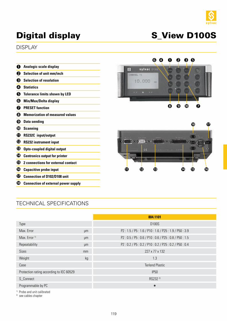
Digital display S_View D100S
119
!
"
#
$
%
&
'
(
)
11
12
13
15
14
16
17
18
! "# $%
&' ( )
1718
11 12 13 1514 16
Analogic scale display
Selection of unit mm/inch
Selection of resolution
Statistics
Tolerance limits shown by LED
Min/Max/Delta display
PRESET function
Memorization of measured values
Data sending
Scanning
RS232C input/output
RS232 instrument input
Opto-coupled digital output
Centronics output for printer
2 connections for external contact
Capacitive probe input
Connection of D102/D108 unit
Connection of external power supply
DISPLAY
TECHNICAL SPECIFICATIONS
Type
Max. Error µm
Max. Error 1) µm
Repeatability µm
Sizes mm
Weight kg
Case
Protection rating according to IEC 60529
S_Connect
Programmable by PC
804.1101
D100S
P2 : 1.5 / P5 : 1.6 / P10 : 1.6 / P25 : 1.9 / P50 : 3.9
P2 : 0.5 / P5 : 0.6 / P10 : 0.6 / P25 : 0.8 / P50 : 1.5
P2 : 0.2 / P5 : 0.2 / P10 : 0.2 / P25 : 0.2 / P50 : 0.4
227 x 77 x 132
1.3
Terlend Plastic
IP50
RS232 2)
1) Probe and unit calibrated2) see cables chapter
Digital display S_View D100S

120
Unit according to technical specifications
Base
External contact (foot-pedal)
Charging unit according to country (904.4000)
Instruction manual
BASIC INSTRUMENT
APPLICATIONS
Mixing of probes and hand toolsMulti-gauging application Multi-gauging application
Digital display S_View D100S

121
MAX. 1
1x
MIXED
MAX. 2 MAX. 1
1x
P2...P50
POSSIBILITIES OF CONNECTION
RS232C
PROBE
SW1
OUTPUT
RS232
SW2
10 V
0 VCENTRONICS
Digital display S_View D100S

122
MIXED
MAX. 64
8x
MAX. 64
8x
POSSIBILITIES OF CONNECTION WITH ACCESSORIES
RS232C
PROBE
SW1
OUTPUT
SW2
10 V
0 VCENTRONICS
Digital display S_View D100S

123
MAX. 48
16x
MIXED
MAX. 64
3x 4x
MAX. 64
16x
50/100 mm
S229
905.2227
POSSIBILITIES OF D110V PNEUMATIC LIFTER
RS232C
PROBE
SW1
OUTPUT
RS232
SW2
10 V
0 VCENTRONICS
Digital display S_View D100S

124
*
MAX. 48
16x
MIXED
MAX. 64
3x 4x
MAX. 64
16x
905.2217
12.5/25 mm
S229 P10/P25
905.4217
5/12.5 mm
S233 P50*901.2010 *901.2011
PROBE
POSSIBILITIES OF D110 PNEUMATIC LIFTER
RS232C
SW1
OUTPUT
RS232
SW2
10 V
0 VCENTRONICS
Digital display S_View D100S

125
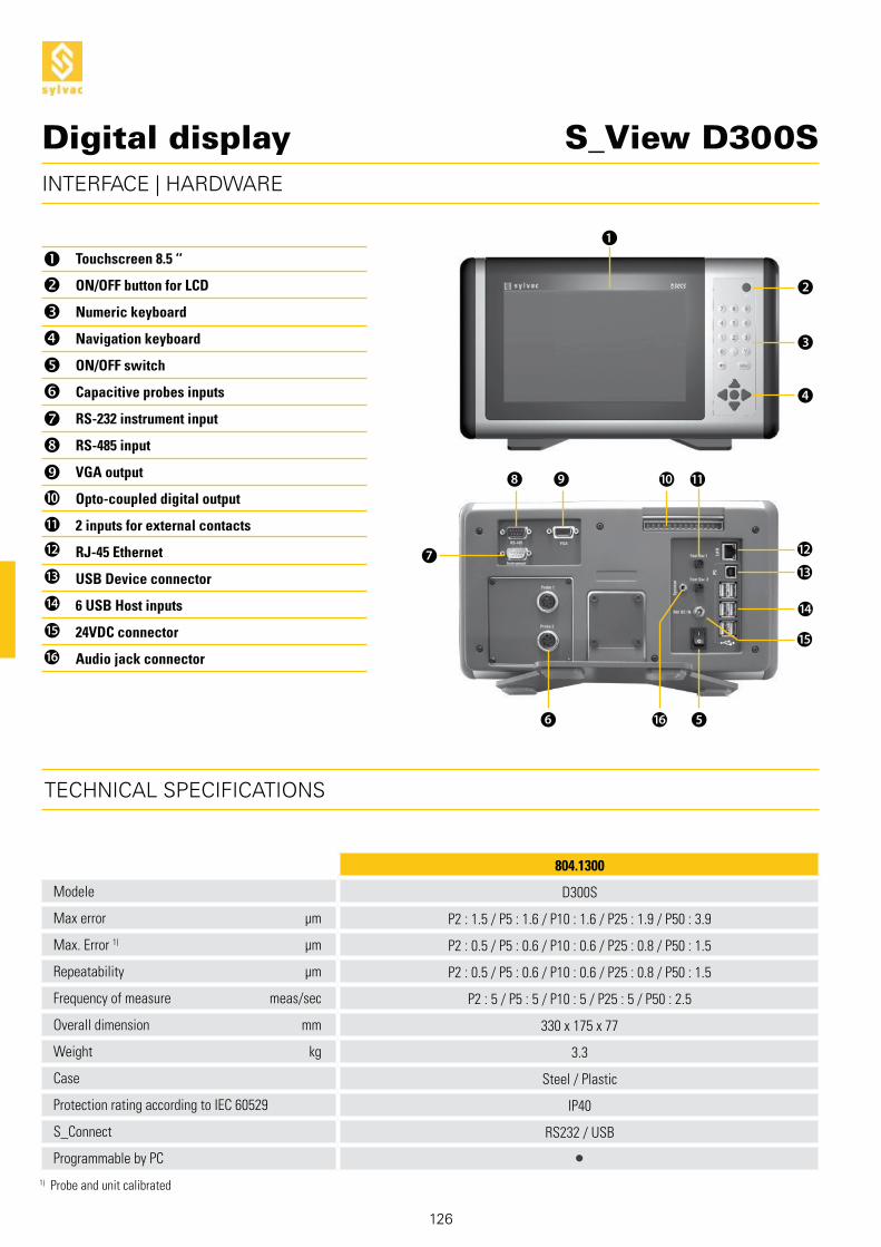
S_View D300S
804.1210
Digital display
DESCRIPTION
Large touchscreen 8.5’’
Ergonomic keyboard protec-ted against liquids
Ergonomic interface configurable according to your needs
126
11
6 16
12
15
14
!
"
#
$
%
&
'
(
)
11
12
13
15
14
16
13
1
2
3
4
5
7
8 9 10
S_View D300S
Touchscreen 8.5 ‘‘
ON/OFF button for LCD
Numeric keyboard
Navigation keyboard
ON/OFF switch
Capacitive probes inputs
RS-232 instrument input
RS-485 input
VGA output
Opto-coupled digital output
2 inputs for external contacts
RJ-45 Ethernet
USB Device connector
6 USB Host inputs
24VDC connector
Audio jack connector
Modele
Max error µm
Max. Error 1) µm
Repeatability µm
Frequency of measure meas/sec
Overall dimension mm
Weight kg
Case
Protection rating according to IEC 60529
S_Connect
Programmable by PC
804.1300
D300S
P2 : 1.5 / P5 : 1.6 / P10 : 1.6 / P25 : 1.9 / P50 : 3.9
P2 : 0.5 / P5 : 0.6 / P10 : 0.6 / P25 : 0.8 / P50 : 1.5
P2 : 0.5 / P5 : 0.6 / P10 : 0.6 / P25 : 0.8 / P50 : 1.5
P2 : 5 / P5 : 5 / P10 : 5 / P25 : 5 / P50 : 2.5
330 x 175 x 77
3.3
Steel / Plastic
IP40
RS232 / USB
Digital display
INTERFACE | HARDWARE
TECHNICAL SPECIFICATIONS
1) Probe and unit calibrated
127
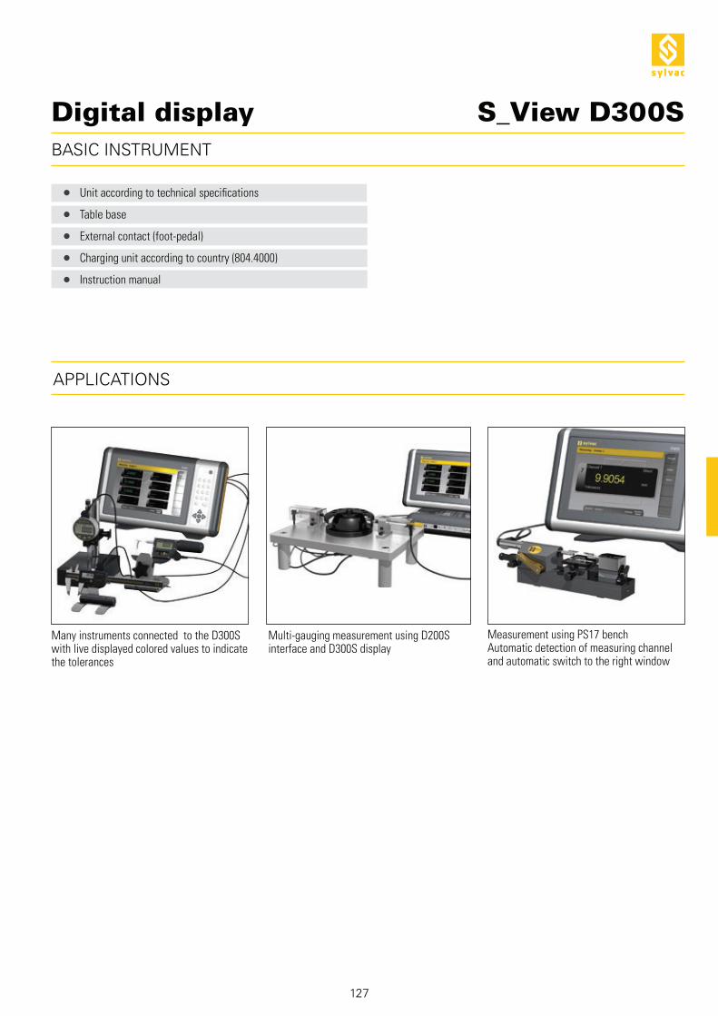
S_View D300S
Unit according to technical specifications
Table base
External contact (foot-pedal)
Charging unit according to country (804.4000)
Instruction manual
Multi-gauging measurement using D200S interface and D300S display
Many instruments connected to the D300S with live displayed colored values to indicate the tolerances
Measurement using PS17 benchAutomatic detection of measuring channel and automatic switch to the right window
Digital display
BASIC INSTRUMENT
APPLICATIONS

128
6x USB1x RS-232
2x8x
S_View D300S
D200S
Digital display
MAX. 6Power supplied by D300S
MAX. 64Power supplied
by USB-HUB
MAX. 64Via D200S
POSSIBILITIES OF CONNECTION WITH ACCESSORIES
PROBE
USB
SW1
OUTPUT
USB
SW2
USB

129
S_View D300S
D302
32x2x
P2...P50
Digital display
POSSIBILITIES OF CONNECTION WITH ACCESSORIES
MAX. 64Via D302
USB
SW1
OUTPUT
USB
SW2
USB
PROBE

130
804.1210
DESCRIPTION
Tolerance indicators
Connection by USB (2x)or RS232 (1x)
Opto-coupled digital output rack
Multiplexer unit S_View D200S
8 inputs for Sylvac probes
Software allowing the treatment of up to 24 channels simultaneously (bargraph)
Connection by USB (2x)or RS232 (1x)

131
DISPLAY/SOFTWARE
Selection of unit mm/inch
Selection of resolution
PRESET function
Sending Data
Tolerance indicators with LED
Min/Max/Delta display
Individual selection of measuring direction
Switchable digital/bargraph display
Global tolerance status of the measured part
Programming channels screen
Sending Sequences of Data
External contact configuration
Electrical external contact configuration
Open / Save configurations
Transfer configuration to D200S unit
TECHNICAL SPECIFICATIONS
Type
Max. Error µm
Repeatability µm
Frequency of measurement
Sizes mm
Weight kg
Case
Protection rating according to IEC 60529
S_Connect
Programmable by PC
804.1200
D200S
P2 : 1.5 / P5 : 1.6 / P10 : 1.6 / P25 : 1.9 / P50 : 3.9
P2 : 0.2 / P5 : 0.2 / P10 : 0.2 / P25 : 0.2 / P50 : 0.4
200 values /second
304 x 171 x 61
1.2
Aluminium profile, Terlend plastic, ABS and aluminium vanished
IP50
USB / RS232 1)
1) see cables chapter
S_View D200SMultiplexer unit

132
Instrument according to technical specifications
Feet for use in vertical position
Charging unit according to country (904.4000)
PC Connection cable type USB (804.1210)
CD with D200S software
Instruction manual
BASIC INSTRUMENT
APPLICATIONS
Dynamic measurement of several diameters, (OD and ID) of a shaft
S_View D200SMultiplexer unit
Multi-gauging application
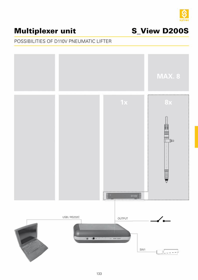
133
1x
MAX. 8
8x
POSSIBILITIES OF D110V PNEUMATIC LIFTER
USB / RS232C
SW1
OUTPUT
S_View D200SMultiplexer unit

134
MAX. 8 MAX. 8MAX. 8
8x8x8x
P2...P50 P2...P50P2...P50
POSSIBILITIES OF CONNECTION
S_View D200SMultiplexer unit

135
D302 / D302a
804.1210925.5609
DESCRIPTION
Multiplexer unit

804.1302 804.1303
D302 D302a
95 x 88 x 55
0.3
136
1
2
3
4
5
6
7
8
10
11
12
13
9
1
2
3
4
5
6
7
8
9
10
11
12
13
D302 / D302a Multiplexer unit
LED Power
LEDS channel
LED RS 485 activity
Port USB de connexion PC
RS 485 output
Ground connector
RS 485 input
External connector
Standard clamping (DIN 35mm)
Jumpers
Analogic output / 24 VDC
Porbes input
9V power supply input
Modele
Max error µm
Max. Error 1) µm
Repeatability µm
Overall dimension mm
Weight kg
Case
Protection rating according to IEC 60529
S_Connect
Programmable by PC
Analog output signal
P2 : 1.5 / P5 : 1.6 / P10 : 1.6 / P25 : 1.9 / P50 : 3.9
P2 : 0.5 / P5 : 0.6 / P10 : 0.6 / P25 : 0.8 / P50 : 1.5
P2 : 0.2 / P5 : 0.2 / P10 : 0.2 / P25 : 0.2 / P50 : 0.4
Aluminium profil / plastic TA 6
IP40
USB / RS 485
TECHNICAL SPECIFICATIONS
BASIC INSTRUMENT
HARDWARE DESCRIPTION
Unit according to technical specifications
Feet (pair)
RS232/RS485 cable
Charging unit according to country (904.4000)
Instruction manual
904.1108
904.1112
904.4000
904.4001
904.4002
904.4003
804.4000
904.4001
904.4002
904.4003
904.4101
904.6001
804.6001
804.1211
804.1073
804.1074
137
D200SD50S D60S D80SD100S
Ø8
0 -9
50
50
50
12
804.1074
60
Ø8
-5 -20
max
i.39
24
9
M3
D300S D302D304
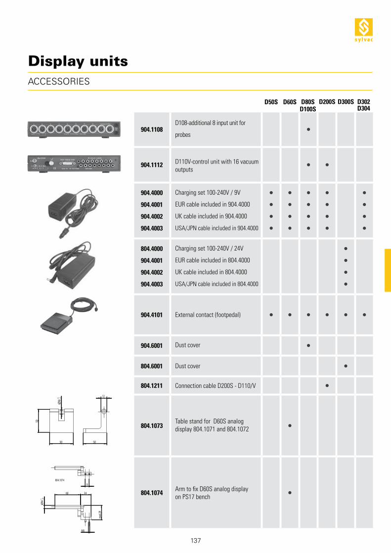
ACCESSORIES
Display units
D108-additional 8 input unit for
probes
D110V-control unit with 16 vacuum
outputs
Charging set 100-240V / 9V
EUR cable included in 904.4000
UK cable included in 904.4000
USA/JPN cable included in 904.4000
Charging set 100-240V / 24V
EUR cable included in 804.4000
UK cable included in 804.4000
USA/JPN cable included in 804.4000
External contact (footpedal)
Dust cover
Dust cover
Connection cable D200S - D110/V
Table stand for D60S analog
display 804.1071 and 804.1072
Arm to fix D60S analog display
on PS17 bench

138


