Download - Innovation Summit 2015 - 4 - CF3

Need for compatibility and future-proof design
CF3™
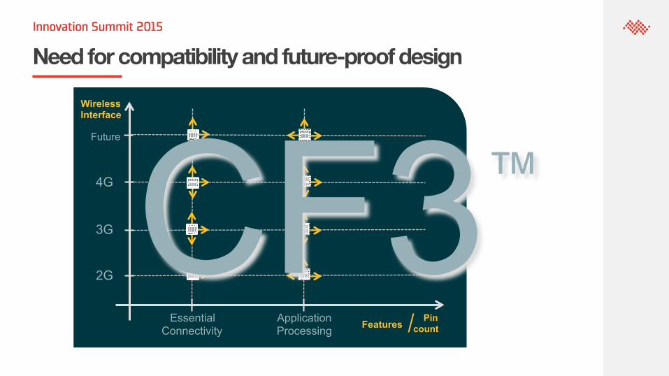
Need for compatibility and future-proof design
Wireless Interface
2G
3G
4G
Application Processing
Essential Connectivity
Pin count Features
CF3™
Future
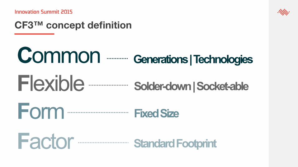
CF3™ concept definition
Common
Generations | Technologies
Flexible
Solder-down | Socket-able
Form
Fixed Size
Factor
Standard Footprint

3 keys to CF3™
Miniaturization • XY dimension convergence
22mm x 23mm
• Innova2ve + cost compe22ve packaging technology

3 keys to CF3™
RF PCB
RF Components RF Components
Baseband PCB
Baseband Components
Miniaturization
RF Components
Baseband PCB Baseband Components
Typical module layout >1,000mm2 ~500mm2 CF3™ module layout
[TOP VIEW] [SIDE VIEW]

3 keys to CF3™
RF PCB
RF Components RF Components
Baseband PCB
Baseband Components
Main Board 1
Main Board 2
Frame Board 0.8mm
1.2mm
Metal Can
Solder
Solder
Miniaturization

3 keys to CF3™
Footprint • Future-‐proof + swappable
• 2 flexible footprint designs

3 keys to CF3™
CORE PINS never change, guaranteed forward / backward
compatibility
EXAMPLE Reset pin will always be: • Pin 11 • Voltage: 1V8 • Polarity: active-low RES
EXTENSION PINS enable additional features without
impacting compatibility
EXAMPLE GNSS antenna will always be on pin 38 in every CF3 module with GPS + Glonass
Footprint
CUSTOM PINS enable unique module-specific features
EXAMPLE MIPI Debug may be on pins 2,8,9,10,60 in some modules

3 keys to CF3™
Footprint
Essential Connectivity footprint
TOTAL
Core Ext.
28 38
66
Application Processing footprint
TOTAL
Core Ext.
62 95
157

3 keys to CF3™
Socket • Common socket for all plaCorms
• Rugged enough to withstand any
environmental requirements

3 keys to CF3™
Socket
snap-in snap-out
solder down
Both options use the same board space
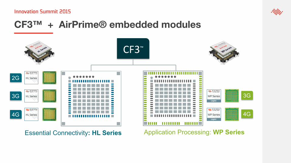
CF3™ + AirPrime® embedded modules
CF3™
Essential Connectivity: HL Series Application Processing: WP Series
2G
3G
4G
3G
4G

CF3™ + AirPrime® embedded modules
Wireless Interface
2G
3G
4G
Application Processing
Essential Connectivity
Pin count Features
CF3™

PLATINUM SPONSOR GOLD SPONSORS
Innovation Summit 2015


