
,.•
-.
THE EFFECTIVE WIDTH OF CIRCUI,AR
CYLINDRICAL SHELLS REINFORCED BY RIBS
'(A Theoretical Study)
by
Bruno Thllrlimann
A DISSERTATION
Presented to the Graduate FaCUlty
of Lehigh University'
in Candidacy for the Degree of
Doctor of Philosophy
Lehigh University
1950

..
..
II
Approved and recommended for acceptance as a
dissertation in partial fUlfillment of the requirements
for the degree of Doctor of Philosophy.
Professor in Charge
Accepted,
Special committee directing the doctoral
work of Mro Br\.U1o Thdrlimann •
Chairman------------

••
...
III
ACKNOWLEDGMENT
The dissertation presents a part of the theoretical
studies made during the oourse of a two years research
program on shell arch roofs carried out at Fritz
Engineering Labaratory, Lehigh University, Bethlehem,
Pennsylvania.
The author is greatly indebted to Dr. Bruce G.
Johns ton, former d1 reotor of Frl tz Engineering Laboratory
who supervised the researoh program and was professor in
oharge for the present dissertation. His advioe and
suggestions are sincerely appreoiated.
Roberts and Sohaefer Engineering Company, Chioago,
Illinois, was sponsor of the researoh program. Many
thanks are expressed to Mr. J. E. Kalinka, vice president
of the oompany, and to Mr. R. Zaborowski, Prinoipal
Engineer at the New·York Office, who was representing
the oompany. The many suggestions reoeived from
Mr. A. Tedesko, o. Gruenwald, W. A. Renner and P. Rongved,
all of Roberts ~nd Sohaefer Coolpany, during several
meetings are sincerely acknoWledged.
The typing of the dissertation was done by Mrs. H.
Bickert and the drawings were prepared by Mr. A. R.
Kephart. Their cooperation is gratefUlly appreoiated.

,~,
.,
IV
TABLE OF CONTENTS
Page No.
Abstract 1
Introduction 1
I. Definition of the Effective Width 4
II. Symmetrical Case 8
1. General Solution of the Differential 8
Equation
2. Effeotive Width of an Inf~nitelyLong 10
Cylinder
Table A 11
3. Effeotive Width of a Semi-Infinite Cylinder 14
4. Use of Superposition in General Cases 17
5. Three Special Cases 21
a.) T- and H-Section with Circular Axis 21
b.) Infinitely Long Cylinder wi th Equally 2~
Spaced Stiffening Ribs
c.) Circular Cylindrical Ring with 24
Stiffener at one End
60 Conclusions
III. General Case
1. Solution of the Differential Equations
2. Miesel's approximate solution
Table B
26
26
26
3~
33

IV.
3. Effective Width of Cylindrical Shells for
the Limiting Case "a"-+ 00
a.) Infinitely Long Cylinder
b.) Semi-Infinite Cylinder
c.) The Case of Axial S~nmetry
4. Conclusions
V. General Remarks on the Application of the
Effeotive Width
1. Symmetrical Case
2. General Case
a.) Statically Determinate Case
b.) Statically Indeterminate Case
V
Page No.
'35
46
54
57
57'
58
60
61
61
62
62
63
63
64
64
65

•
•
•
Appendix: Limitations of the Effective Width
by Stability
1. T-Beam wi th Straight Axis
2. Cylindrical Shell
3. Recormnendation for Further Studies
Tables 1 to 4
Figures 1 to 24
Notations
List of References
Vita of Author
VI
Page No.
66
66
'70
72
75-83
85-101
103
108
110
l
•
..
•
•
1
Abstract
Formulas are derived for the effective width of
ciroUlar cylindrical shells reinforoed by ribs in the
oiroumferential direotion. In cases where the shell
can be oonsidered to extend to infinity the effective
width depends on two parameters, ~ahi and A= n J~ '.The first parameter is a function of the radius "a"
and the thiokness h of the shell, the seoond oontains
in addition the factor n representing the influenoe of
the stress distribution in oircumferential direction.
Certain simplifications, the influenoe of which
was investigated and found to be insignifioant,are
introduced in order to calculate tables and ~esent
graphs for the effective width in different cases.
For the limiting case where the radius tl a " of
the shell increases to infinity the correspondence to
the effective width of a T-Beam with a straight axis is
established •
Introduction
The problem of the effective width of T-Beams with
a straight axis (Fig. 1) was extensively inves~igated
during the past 30 years (see Ref. (1) to (5»*. The
- - - - - - - ~ -- - - - - - - - - - - - - - - ~ - -*For list of references see p. 108.

•
•
. .
2
aotual stress distribution in the flange is replaoed
by an imaginary oonstant stress distribution over the
effeotive width. Taking instead of the aotual flange
a flange of width equal to the effeotive width,the
ordinary beam theory (oross sections remain plane)
can be used to oalculate the fiber stresses and the
defleotion of the rib. The advantages of this procedure
are quite obvious.
The case of a curved T-Beam was taken up by U.
Finsterwalder (6), H. Bleioh (7) and Th. v. Karman (8)0
In Ref. (6) the general unsymmetrical case is treated
with certain simplifioations and the solution is not
developed for practical applications. Ho Bleich
investigates the bending of curved knees of T- and H
section. In Ref. (8) a formula* for the effective
width is given which does not coincide with the results
of this dissertation.
The application of cylindrical shells stiffened
by ribs in circumferential direction ('Fig. 2) has
entered many different fields, including shell arch
roofs, airplane fuselages, pressure vessels, s~bmarines,
hot metal ladles, etc. The analysis of such st~uctures
- ~ -- -- - - - - - - - - - -- - - - - -- - - - - -*v.Karman gives the formula ~ :: 0.54 yah' without any
derivation. In the present dissertation it is shownthat the numerical coefficient is not a oonstant.

•
•
3
is very involved,and there seems to be a specific need
for establishing the effeotive width of cylindrical
shells stiffened by ribs in order to simplify their
analysis.
The present dissertation is .a comprohensive study of
this problem. Special attention was given to a simple
presentation of the results in order to make them
applioable tor pract~cal design purposes. An extra
study was made to investigate the relation between the
straight T-Beam and the effective width of the shell
in case the radius of the shell increases to infinity•
The topics treated are as follows: First the
effeotive width is defined. The case of axial symmetry
is treated pext. This rather simple case leads to the
development of the fundamental ideas and prepares to
attack the general case (unsymmetrical case). Finally
the limit When the radius "a" of the shell increases to
infinity is found to coincide with the resUlts of the
problem of the T-Beam with a straight axi s. Some
general considerations regarding the application of
the effeotive width in practical problems are discussed.
(1)
I,
4
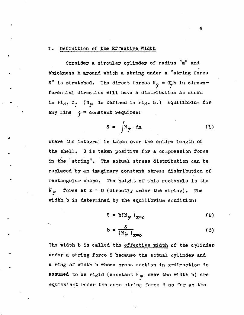
I. Definition of the Effective Width
Consider a circular oylinder of radius "a" and
thickness h a.round which a string under a "string force
S" is stretched. The direct forces N5" = orh in circum
ferential direction will have a distribution as shown
in Fig. 3: (N~ is defined in Fig. 5.) Equilibrium for
any line J = constant requires:
S = fN J>' dx
where the integral is taken over the entire length of
the shell. S is taken positive for a compression force
in the "string". The actual stress distribution can be
replaced by an imaginary constant stress distribution of
rectangular shape. The height of this rectangle is the
Nj' foroe at x = 0 (directly under the string). The
width b is determined by the eqUilibrium condition:
•
S = b{N~ )x=o
Sb =
(N g, )x=o
(2)
( 3)
The width b is called the effective width of the cylinder
under a string force S beoause the actual oylinder and
a ring of width b whose cross section in x-direction is
assumed to be rigid (constant N1 over the width b) are
equivalent under the same string force S as far as the
•
•
5
direct force (N" ).x=o and the strain ( c1 ).x=o are con
cerned.
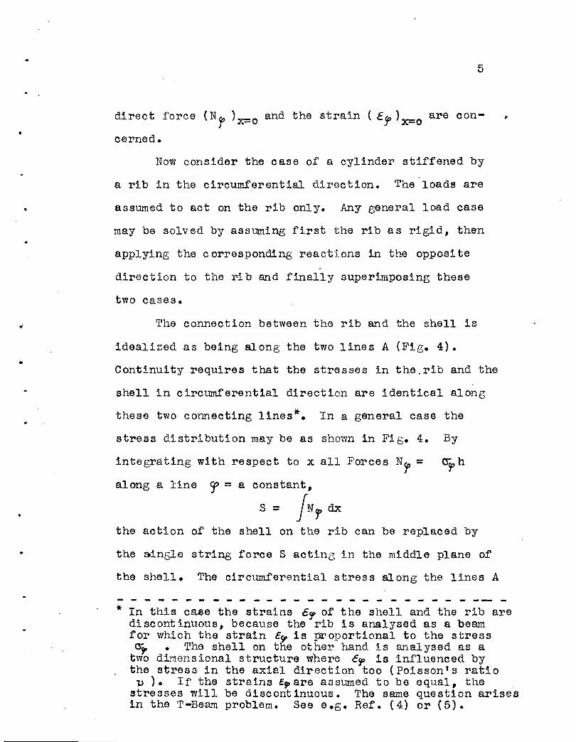
Now consider the case of a cylinder stiffened by
a rib in the circumferential direction. The loads are
assumed to act on the rib only. .Any general load case
may be solved by assuming first the rib as rigid, then
applying the corresponding reactions in the opposi te.
direction to the rib and finally super~lposing these
two cases.
The connection between the rib and the shell is
idealized as being along the two lines A (Fig. 4) •
Continuity requires that the stresses in the.rib and the
shell in circumferential direction are identical along
these two connecting lines*. In a general case the
stress distribution may be as shown in Fig. 4. By
integrating with respect to x all Forces N~ = o-~ h
along a line ~ = a constant,
S= fN f dx
the action of the shell on the rib can be replaced by
the oo.nsle string force S acting in the middle plane of
the shell. The circumferential stress along the lines A
- - - - - - - - - - - - - - - - - - - - - - - - --- -* In this case the strains c~ of the shell and the rib are
discontinuous, because the rib is analysed as a beamfor which the strain E~ is proportional to the stressa;. • The shell on the other hand is analysed as a
two diMensional structure where crp is influenced bythe stress in the axial direction too (Poisson's ratio
lJ ). If the strains E9' are assumed to be equal, thestresses will be discontinuous. The same question arisesin the T-Beam problem. See e.g. Ref. ('4) or (5).

6
is called uA. The direct force N!!f of the shell along
these lines is the product of the stress GA and the
thickness h of the shell. If the actual stress distri-
•
bution is again replaced by a constant stress distri
bution over the effective width b, Eq. (3), the force
S becomes:
( 4)
( 6)
For an arbitrary cross section r= constant assume
the total bending moment to be M, the normal force N to
be zero. The stress distribution through the depth of
the rib is assumed to vary linearly (ordinary beam theory).
The action of the shell on the rib is represented by
the string force S as given by Eq. (4), acting in the
middle plane of the shell. By taldng moments around the
axis n-n, the moment of the section is:zL
M = Z fZtdZ + SZA (5)
uDue to the straight line distribution of the stress
<r"can be written as function of the• over the rib section
stress cr"A at A:
uA()= - z. zA

..
..
7
By use of Eq. (4) and (6) the moment Mis:
M = ~ L}:~dz + ZA bh ] (7)
Making use of the assumption that N should be zero another•
relation can be deri ved:
;ZLN = z C3'tdz + S = 0
u ·z
+ bhJN =~ . [ zjz~dz = 0 f8)
The parenthesis of Eq. (8) represents the statical moment
of the cross section consisting of the rib and a flange
equal to the effective Width of the shell around the
centroid (axis n-n). In Eq. (7) the parenthesis is the
moment of inertia of the same cross section. A similar
derivation can be made for the case of a normal force N
and the bending moment M equal to zero.
The following conclusions can be drawn:
1. ~y replacing the actual combination of rib and
shell by a T-section consisting of the rib as web and
the effective width b of the shell as flange, the ordinary
b h ( r.- __ !"rz )eam t eory ~ can be used to calculate the fiber
stresses G"u and G"'L and the deflection of the rib.
This cross section will be called the effective oross.section. The string force S acting on the shel~ is
found by Eq. (4).
•
8
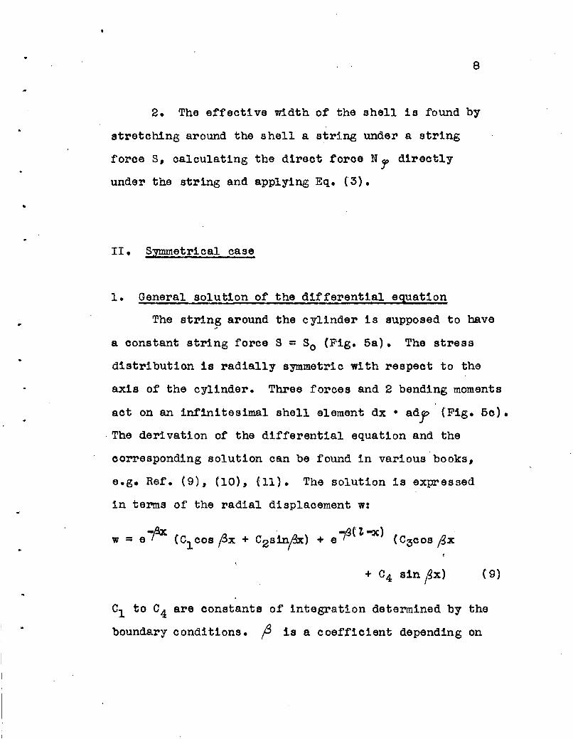
2. The effective width of the shell is found by
stretching around the shell a string under a string
force 5, calculating the direct force Nl' directly
under the string and applying Eq. (3) •
II. S:wmetrical case
•
General solution of the differential equation
The str1n~ around the cylinder is supposed to have
a constant string force S = So (Fig. 5a). The stress
distribution is radially symmetric with respect to the
axis of the cylinder. Three forces and 2 bending moments
act on an inf1nitesimal shell element dx • adf (Fig. 5c) •
. The derivation of the differential equation and the
corresponding solution can be found in various books,
e.g. Ref. (9), (10), (11). The solution is expressed
in terms of the radial displacement w:
+ C4 sin (!>x) (9)
01 to 04 are constants of integration determined by the
boundary conditions. f 1s a coefficient depending on

9
the shell radius "a", the shell thickness hand Poisson t s
ratio V of the material:
'.. (10)
..
w has the form of two damped oscillations, one
originating from the boundary x = 0 and the other one
fran the. boundary x = 7,. If the latte!, is sufficiently
far removed so as to be considered at infinity (this
condition is discussed on p. 25) the second part of
Eq. (9) may be dropped, leaving the first two terms:
(11)
All forces and moments in the shell can be expressed as
functions of w, e.g. the direct force in circumferential
direotion:
Of special interest is the string force So(x) at x:00
. So(x) = JNJ'dx =:~ e-p. [( 01+02 ) coop,.:
x _t Ol-C
2) oin px] (13)
Any unknown quantity suoh as a moment or a displacement,
is of the form
10
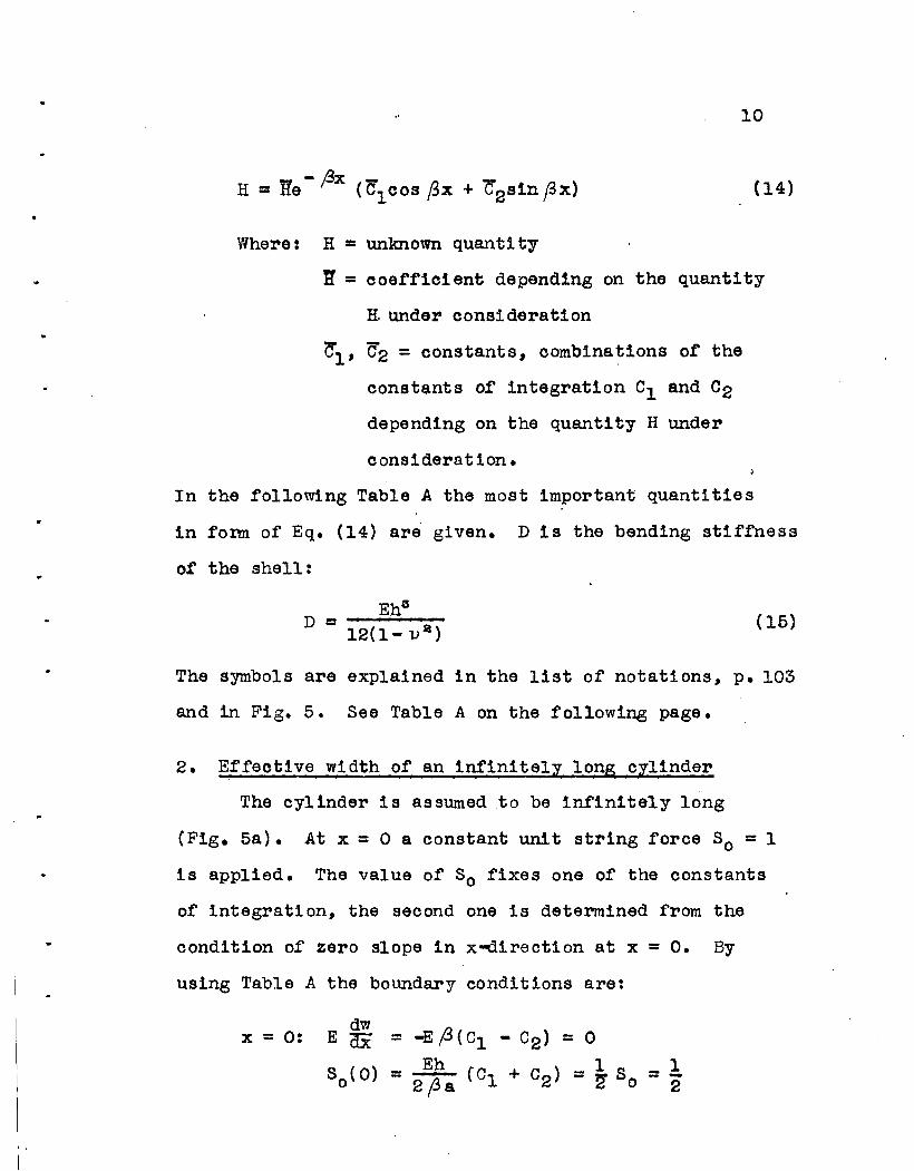
(14)
Where: H = unlmown quanti ty
~ = ooeffioient depending on the quantity
H. under oonsideration
~l' C2 = constants, oombinations of the
oonst$nts of integration C1 and C2
depending on the quantity H under
consideration.
In the following Table A the most important quantities
in fonn of Eq. (14) are given. D is the bending stiffness
ot the shell:
(15)
The symbols are explained in the list of notations, p. 103
and in Fig. 5. See Table A on the following page.
2. Effeotive width of an infinitelI long 0Ilinder
The cylinder is assumed to be infinitely long
(Fig. 5a). At x = 0 a constant unit string force So = 1
is applied. The value of So fixes one of the oonstants
of integration, the seoond one is determined from the
condition of zero slope in x-direction at x = O. By
using Table A the boundary conditions are:
x = 0:dw
E ax = -E(.3(Cl - C2) = 0
S (0) = ..!!L. eCl + C2 ) = ~ S = 1.o 2(3a G 0 2

..
H
Ew
E~dx
s (x)o
E
-Ef3
Eh--&Eh
2/3&
2D(32
2DB 3,
TABLE A
~1
C1
-(C - C )1 2
11
.. General case:w _Ax
H = ne r r 'e1 cos fix +
•
..12
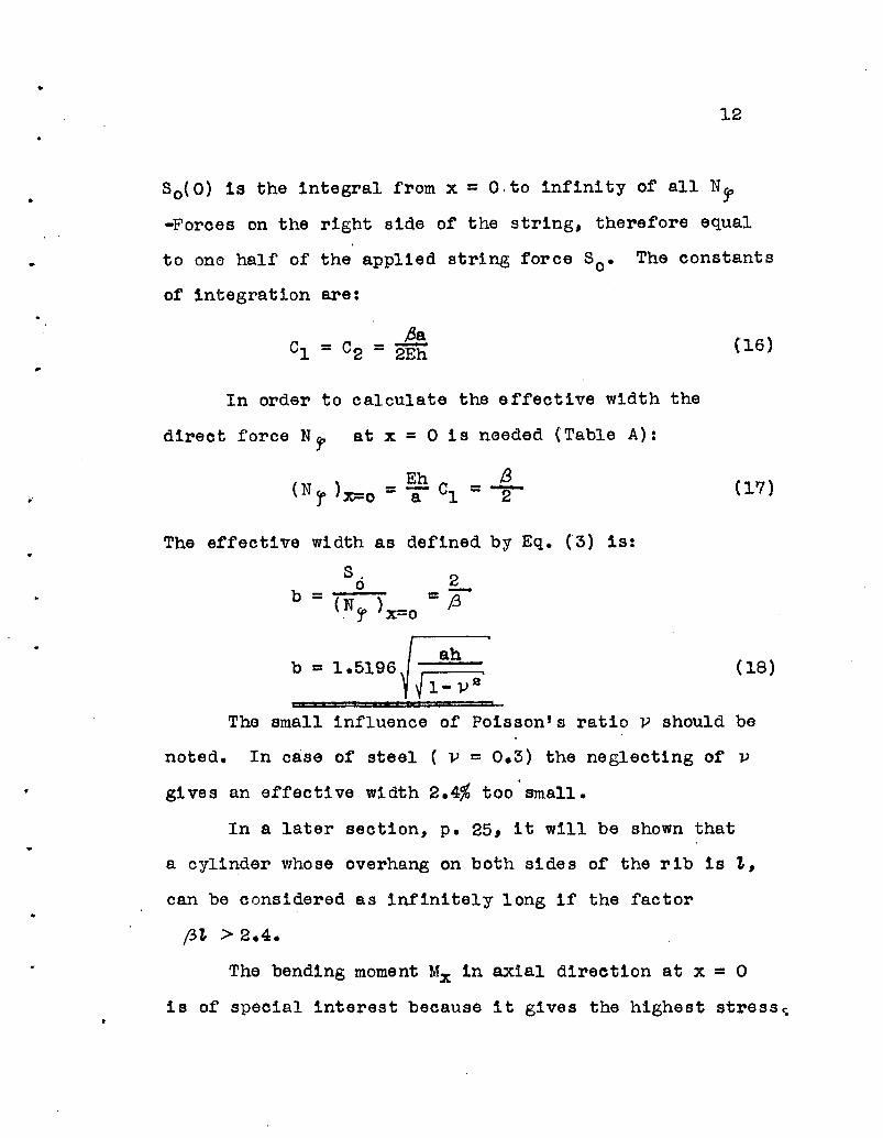
So{O) is the integral from x = O.to infinity of all N~
-Forces on the right side of the string, therefore equal
to one half of the applied string force So. The constants
of integration are:
C - C - A1 - 2 - 2Eh
In order to calculate the effective width the
direct force Nl' at x = 0 is needed (Table A):
(16)
f3=2 (17)
The effective width as defined by Eq. (3) is:
S6 2
b = {.N~ )x=o =73
b =1.5196~V{l::va'
I I
(18)
The small influence of Poisson's ratio V should be
noted. In case of steel ( v = 0.3) the neglecting of v
gives an effective width 2.4% too'small.
In a later section, p. 25, it will be shown that
a cylinder whose overhang on both sides of the rib is t,
can be considered as infinitely long if the factor
(3t > 2.4.
The bending moment Mx in axial direction at x = 0
is of special interest because it gives the highest stress~

•
13 .
The moment is (Table A and Eq. (16»:
(19)
,.
A simple expression ror the ratio of the cross
bending stress ~x and the circumferential direct stress
()1 oan be deri ved by making use of Eq. (17), (19).
The direct stress ar is equal to the direct force N~ per
unit width divided by the shell thickness h. Similarly
the maximum bending stress <>x is round by dividing>
the moment Mx per unit width by the section modulus
or the shell
G"x 6Mxh--- =--;--()r. x=o h NT
G"'x 1.7321
C>(p = "1 - V :a'J X=O V
= J-1-_....3....1)--='2
(20)
The use or Eq. (20) ,is quite obvious. It gives
with a minimum or calculation the maxtmum cross bending
stress G'x ir the stress csr is known. It should be kept
in mind that Ux is the larger stress.
The values or So(x), N fJ> and Mx at a distance x
,rrom the applied string rorce So are calculated by replaoing
the oonstants of integration in Table A as given by
Eq. (16):

..1 -fix.So(X} =~ e cos fix • So
= %e -,gx (cos f3x + sin f3x) • So
14
(21)
(22)
-Mx = - -!.- e -Ix (cos (5x - sin ax)4a(3 r • So (23)
.-By putting:*
i1
( (3x) -= e- (1x oos fix
i 2( ~x) = e - f3x {cos (3x + sin (3x)
i 3( (3x) = e - fJx (" cos (3x - sin ~x)
These equations can be written:
The values of the function i are tabulated in
Table 4/0. (Fig. 18.)
(24)
(25)
(26)
(21a)
(22a)
(23a)
3. Effective width of a semi-infinite cylinder
The rib is at the end x =a of a semi-infinite oylinder
(Fig. 5b). A constan~ string force So = 1 is applied at
- ~ - - - - - - - - - - - - ~ - - - ~ - ~ - - -- - ~~- - -* The functions iI' 12 and i3 are tabUlated in Ref. (IO),
p. 394. Table 45 (symbols are changed).

15
this end. For this case the bending moment Mx is
zero at the end and the string force 30 (0) is equal
to unity. (Table A)
x = 0: Mx = -2D ,6IllC2 = 0
Eh80 (0) = 2~a (Cl + C2~ = 8 0 = 1
The constants of integration are therefore:
..
Nl' at x = 0 follows from Table A:
Eh( Nr )x=o = a Cl = 2 f3
And the effective width b is (Eq. (3»:
} (27)
(28)
So 1b = =-
{N r )x=o 2/3
b = 0.3799~ ( 29),-V1- Villi
Comparison with Eq. (18) shows that the effective width in
this case is 4 times smaller than for an infinitely long
cylinder. Poisson t s ratio 1> is again of minor influence.
The ratio of the maximum bending stress ~x in
axial direction to the circumferential direct stress ~r
at x = 0 will now be determined. The bending moment

•16
( 31)~max
MX is (Table A, Eq. (27»:
Mx :: 2Df32 e -j3x Cl s inf3x :: a~ e- (3x sin f3x ( 30)
7rM has 1ts maximum for f3x:: ~ and may easilyx
be found by differentiating Mx with respect to x and
putting the result equal to zero:
1 _ 7r '1r:: - e T sin 4'"ap
..
Nf at x = 0 is given by Eq. (28). The ratio of
the two stresses are:• ()x 6~
G"'co = hNr) ·maxe;; 'ir
3 -. 7r:: e lr' s1n-r1-l)2 ':I:
(32)
It is
and (32), the
Applied to a
remarkable that in both cases, Eq. (20)()x
ratio ~ is independent of the shell d~ensions.
Cfdesign problem this means that by making the
shell thicker the cross bending stress Gx decreases
only insofar as the circumferential stress decreases, the
ratio of the two stresses remaining constant.
..
The S-Force, the direct force N 'f and the bending
moment Mx at a distance x due to a string force So at the
end of the semi-1nfinlte cylinder are (Table A, Eq. (27»:

..17
So(x) - f3x So ( 33)= e (cos fiX - sin f,x)
N~ :: 2(3e- (3x cos (3x • So ( 34)
I1fx = ..1... e - (3x sin px • S (35 )a~ 0
They are functions of the par9Il1et~r (3x and can be
written:
So(x) = ~ (f.3x) So
~Ncr = 2.6322 t~ s2( (3x)So
Mx = 0.7698 ~~ • {l: lJ ." sS! f->xlS o
Where: sl( ~x} = e-PXc-cospx - sin~x}
s2( (Jx) = e - (Jx cos (3x
s3( px) = e - ~x s~n (Jx
(See Table 4/0 and Fig. 1~
( 33a)
( 34a)
( 35a)
( 36)
( 37)
(38)
::4. Use of superposition in general oases
In case of a circular cylinder extending a distance
11 to the right and a distanoe l2 to the left of the rib
the @Bnera1 solution, Eq. (9), must be used. The two
boundaries x = t 1 and x = -t2 furnish 4 boundary conditions.
The condition of continuity at x = 0 gives two more
conditions. This system is sufficient to solve Eq. (9).

•
..
•
18
Nevertheless it may be seen that the sOlu~ion becomes
very complicated in the general oase. For some special
problems, as treated 1n the following section, symmetry
conditions introduce essential simplifications.
In a general case a solution by superposition is
muoh simpler. Consider as an example the case where..
11 = t is finite, 12 on the othe~ hand extends to infinity
(Fig. 6);, The aotual case QJ can be thought of as a
superposition of the cases @, @, and ®. Case ® is an
infinitely long cylinder with a unit string force
80 =1 at x =O. Making a cut at x = 1 it may be seen
that the action of the left part on the right one consists
in a string force 80 (1) and a bending moment (MX)x=I.
In @ an inf1ni tely long cylinder is acted upon by an
opposite string force 80 = -1 at x =2t. The bending
moment r~ at x = t is acting in the opposite sense
compared to case ~ the string force·soCt) on the other
hand has the same dire9tion. Case @ is a semi-1nfini te
cylinder at the end of which a string force So = 2So(1)
is applied. By adding up the cases @, @ and @ no force
or moment at the cut x = ~ is left over and the boundary
conditions of case (1) are fUlfill ed. For determining
the effective width the direct force N1 at x =0 must
be known. The cases ®, @ and @ were already solved

,
• I
,19
before (Eq. (21) to (23) and (33) to (35»:
Case ~ Eq. (22) (N~)x:::o ::: -'f-Case @: Eq. (22) (N1)x=2~ ::: - 4- e-2,B~(coS2f3t+s1n2j3t)
Case ~ Eq. (21),(34) (Nt)x=~ = e-,.8tcos~~ ,. 2,Be-"g1,coBft~
Case CD = ® + ® + ®
(N,.)x=o =~[1+e -2,1n( 4cos'73l - cos2,Gl - S1n2ftl1]
(Nl"lx=o =~[1+e~l(2+coS2/H - S1n2/3l1] (391
.'
Replacing Nr in Eq. (3),the
So r_ 1b ::: (i)' = 1.5196'{ah(1-p 2) if·
l' x=o
or: b = 0 ( tS~)~1 V~i
effective width is:
1
1+e-2Pt{2+COS2~1,-si~t)
( 4Oa)
( 40)
Where: (40b)
•
Eq. (40) checks for the limits 1, =~ with Eq. (IS)
and ~ ::: 0 with Eq. (29).
For the bending moment Mx at x = 0 an expression
can be bUilt up in a similar way:

20
Case (2): (23) (MX)X=O = 1Eq. --
4af3
Case @: (23)1 -2f3't
Eq. (Mx)x=2't = 4af3 e (cos2ftt-sin2j37,)
Case ® Eq. (21)&{35) (Mx )x=7, = e-f3't cos(3't • tp e-,f!l,slnp7,
(41 )
or:
1""6 -2j!t (cos2ft't+sin2t3t)•
1+e~P't(2+cos2~7,-s1n2Bt)
(42a)
(42)
•
Where: f'l ( f3 't) ~ 1-6 -2,81, ( Cos2&'t+s in2@ ) 0 1.7321 ( 42b)1+e-2~"'(2+COS2ft~-sin2ft't)
The functions 01{ (3't). Eq. (40b), and 1\{ ft't),
Eq. (~2b) are tabulated for different values ~7, (Table 1).
They are also plotted in Fig. 14 and 15.
The use of' superposition gives solutions for many
other problems. Due to the considerable damping of all
forces and moments sufficiently far removed from the rib,
any influence at a dlstance 2 j3t >7r can be neglected•

•
21
5. Three speoial eases
The general solution of axially symmatrical bending,
given by Eq. (9), was used for the solution of the following
three problems:
a.) T- and H-section wi th circular axis:
Curved knees of T- or H-seotion of frames are
typioal exan~leso The moment around the knee can be taken
as constant and therefore the stress distribution has
~1 symmetry. Fig. 7a shows two examples. For finding
the effective width a constant tmit string force So = 1
at the location of the web is applied. The action of
this string force is identical to a constant radial line
load p =~ So =~ (see Fig. 7b). Due to symmetry
conditions it is sufficient to analyse the right leg'
of the flange only. At the free edge x = 1, the bending
moment Mx and the shear force ~ are ~ero. At x = 0
dwthe slope ax is zero and the normal shear ~ is half of
the applied radial line load p:
x = 0:
(43)
x = t:

..
..
22
The 4 conditions (43) are sUfficient to solve Eq. (9)
for the 4 constants of integration C1 to C4 • EventuallyI
the expressions for the direot force NT and the bending
moment Mx at x = 0 are £ound. The solution for the
effeotive width, Eq. (3), is:
. 1b =1.5196 Jah' (1-u2 ) - 4' sln~fn + sin2@1, (44)
oosh2~1, + cos2~t+2
or:sip.h2A1, + sin?#t
C2(~t) =1.5196 cosh2~1, + cos2p1,+2
The ratio ,of the cross bending stress
(44b)
( 44a)
Ox to the
or:
direct stress Gfat x = 0 is:
C>x = 1.7321(1"'1l2 )- ft oosb2@1, - cos2Atcr", x=o cosh2,'3t + c oS2f31,+2
cosh2.8! - cos2Atf 2{ ;37,) = 1.7321 cosh2/U + oos2f>t+2
(45)
(45b)
(45a)
•
Tables and graphs for the functions 02 and f2 are
given for different values of pt. (Tabla 1, Fig. 14 and 15).
b.) Infinitely long cylinder with equally spaced stiffening
ribs:
On a long cylinder stiffening ribs are placed at
equal distances 27, (Fig. 8). Eaoh rib is assumed to be
subjected to the same axially symmetrioal foroes. Examples

23
of this type are numerous, e.g. pressure vessels, pen-
" stocks, etc. It is sufficient to consider the. part
from x = o to x .= 1, as shown 1n Fig. 8. A unit string
force So = 1 at x = 0 produces to its left and its
.. right side the normal shear forces:
The boundary conditions for the above mentioned
part are:
I
•
dwx = 0: ax = 0
( 46)
x = 1,:.dwdX = 0
( 47)
Solving for the 4 constants of integration 01 to
04 of Eq. (9), expressions for the effective width andUx
the ratio --- under the rib are derived:u1
b = 1 5196'Jah ' (1-v 2 ) - t c 08h2f31, - c 082,B1,•. sin~1, + sin2p1,
•
G"'x-cr.f x=o
2 - 1 s1nb2,B1, - sin2,t31,= lo7321{1-v) ~ sinb2fi1, + s1n2pl, (48)

., .
The terms depending on f3t are again tabulated
(Table 1 and Fig. 14 and 15).
b =";>( ;3l) J t:_p.' '
24
( 47a)
( 48a)
I
..
Where 03( (3t) and f 3C (3 t) stand for:
C3( (37,)cosh2At .. cos2Bt
(47b)= sinh2,8t + sin2,.Bt
f 3 ' (37,)sinh2(3t - sip2f3t
(48b)=sin~t + sin2j3t
c.) Circular cylindrical ring with stiffener at one end:
A circular oylindrical ring of length'" is stiffened
at one end by a rib (Fig. 9). Angles and cl~els with
a circular axis belong in this category. The boundary
conditions in case of a unit string force So = 1 at
x =0 are:
..
•
x = 0:
x = t:
dlawMx = D dx2 = 0
dBw 1"x = D dx8 = i
( 49)

e.
25
Eventually the expression for the effective width
is found:
~ 2) - i- cosh2A7. + 00s2(31, - 2b = 0.3799yah (l-~ s1nh2~1, - sin2#7.
_ oosh2&7. + 008241 - 2By writing: C4(~7.) - 0.3799 sinh2p7. _ sin2p1,
( 50)
(50b)
(50a)
By oomparing Table 1 and Fig. 14 and 15,it becomes
apparent that in all cases the effective width a.nd theG""x
ratio~ oonverge ra.pidly to the value.s of the infiniter
or sem1-1.nfin1 te cylinder. If the factor ;S7. > 2.4
( ~7. = 2.4 is shown in Fig. 14 and 15 by a dotted line),
the oylinder oan be taken as infinite or semi-infinite.
The error result ing from this simplification is smaller
then 5%,

..
26
6. Conolusions
For the case of axial S'Y!JlIlletry (the stresses and
deformations are constant in circumferential direction)
simple expressions for the effective Width b were
derived; b was found to depend on the dimensions (radius lI a ll#
thi~kness h, length ~) and the material (Poisson's
ratio v) of the shell only. The influence of v is very
small. In case of steel ( P = 0.3) it is 2.4%.
The ratio of the maximum cross bending stress ~
to the direct stress in circumferential direction ~1 at
the rib revealed, that in certain cases where the shell
is continuous over the rib# o-x is the higher of the
two. In case of an infinitely long cylinder:
Eq. (20): G"x = 1.7321 (l-P 2) - ~ • Of •
In the following chapter III the effective width
for a general case of loading will be derived. It will
be found that a new parameter 1. bas to be introduced
depending on the variation of the stresses in circumferen
tial direotion.
III o General Case
1. Solution of the Differential Equations:
The problem consists of finding the forces, moments
and displacements of a cirCUlar cylindrical shell under

• 27
an arbitrary string force (Fig. lOa).
s =GO 00
E s cos nco + r s' cos nfDn=O n J n:::1 n J
(51 )
S is presented in form of an infinite Fourier Series.
In the following it will be sufficient to deal with one
term of this series
S = Sn • cos nj'
.•
( 52)
J
n gives the number of the harmonic under consideration
(n • number of complete waves of the string force S
around the cylinder). n =0 reduces to the case of axial
synnn~try.
The internal forces and moments acting on an
infinitesimal shell element dx • adp are shown in
Fig. lOb. The displacement of the element is expressed
in 3 components, u in the direction of the x-axis,
v in circumferential direction and w in radial direction,
positive if directed. outwards. By assuming Hook's law
and the well known principle of the plate theory,that a
line perpendicular to the middle surface of the shell
remains ~rpendicular to the defomed middle surface,
all internal forces and moments can be expressed as
functions of the 3 displacement components u, v and w
and their derivatives. Inserting these expressions in

•
•
28
the equations of equilibrium of an infinitesimal particle
of the shell, a system of 3 partial differential equations
for the 3 components of displacement is found*:
gl (u, v, w) =0
g2 (u, v, w) = 0
g3 (u, v, w) = 0
53
..
•
g stands for a fUnction of u, v, wand its partial deri-
vatives.
Solutions for the case where boundary conditions
for the boundaries x = constant can be arbitrarily chosen
were presented by K. Miesel, Ref. (12), U. Finsterwalder,
Ref. (6) and Aas Jacobsen, Ref. (13). Finsterwalder
simplifies the problem by assuming the moments M1 = MSOx
=MXf =o. Aas Jacobsen finds an approximate solution
by expressing the moments and forces as functions of the
radial displacement w only (as it is done in the plate
theory) •
Miesel gives a complete solution of the problem.
A ver~ brief summary will be given here in order to
understand the simplifications which will be introduced
- ~ - - ---- - - - ~ - - - - - - - - - - - - - ~ - -* For derivation see Ref. (9), (lO), or (11).

"
.'f
..
•
29
later on. For a complete derivation Ref. (9) or (12)
should be. consulted. By assuming the following form
for the three components of displacement**:
where Un(x), Vn(x) and Wn(x) are functions of x only,
the three partial differential equations (53) for the
three unknowns u, v, and w become total differential
equations with constant coefficients. T~ solution
parallels the one made by Levy for solving the plate
equation*. The three unknown functions Un(x), Vn{x)
( 54)
*
..
and Wn(x) are of the form:
Un = Aek~
Vn = Be ~S (55)
W =Oe A:~n
Where s= x-aIC = constant
- - ~ - ~ - - - - ~ ~ - - - - - - - - - - - - ~ - - - -** Miesal actually operates with the three quantities
u {) dw ...a' [r and = ox; see Refo (12), p. 35.
See Ref. (10), p. 125.

{
•
•
30
Inserting expressions (55) in the equations (53),
:3 linear equations for the unknown A, B, and Care found o
This system has a solution dif~erent from A =B = C = 0
only if the determinant of the coefficients of A, B,
and C is zero. The latter oondition furnishes a 4th
order equation for the ceofficient ~2.
The a roots for ~ are:
ttl = - Ji2 - i~l JC = -fi4 - i}J-35
~ = -)J-2 + i;Ul IC = -fl4 + if£32 6
( 56)1C3 = + f'-2 - i P1 1C
7 = +)t4 - ifi3
~4 = +.#2 + i P lIC =+)A- +i~a 4 3
To each root ~1 there oorresponds a particUlar
integral of the equations (53) with the constants of
integration A , B , and C • The general solution fori i 1
the radial displacement w is for exa~ple:
W =[8 -,"2~ (01
8 -1}L1S+ 0281/<1~ )
t""2(~-a) (·-1)ll~ ifll~)
+ e C3e + C46
~)t4~( -1,..lt3 S i fi:3~ )+ e c5a + c
6a
p. (~_!). -i)t ~ i)J 5]+ e 4 a (c7e 3 + Cae :3) cos nf
( 57)

..
-..
...
31
Obviously w has the form o~ 4 damped oscillations,
two originating from the boundary ~ = 0 and the othert
two from the boundary S= ii. If the latter boundary is
sU~~iciently ~ar removed it does not influence the
boundary 5= 0 and the corresponding part in Eq. (57)
can be neglected.
Actual calculations show that ~rom the 2 oscillations
starting from S = 0 the with the-:-~"E,
isone e power-:-A4~
by far predominant. The with the isone e power
zero for the two cases n =0 and n = 1. For higher values
of n it stays very small. Miesel makes use of this
property to derive an approximate solution where only
the underlined part of Eq. (57) is retained. It can
be shown -that this approximation parallels the simpli
fications introduced by Gecke1er (Ref. (14») in the bending
theory of spherical and conical shells.
The follOWing derivations are based on Miesel's
approximate solution,the value of which will become
especially apparent by the correspondenoebetween the
T-Beam problem and the effective width of a cylinder
for the limiting case where the radius'~" increases to
infinity (see Chapter IV).

•
32
2. Miesel's approximate solution:
Only the underlined part of the general solution
(57) is taken. By putting the equation in its real
form any unknown quantity H, where H stan~for a force,
moment or displacement,' has the fonn:
In the following Table B the most important forces,
moments and displacements are given in this form. The
2 constants· of integration are C and r.)£l and fJ'2
are coeffioients depending on the shell dimensions,
Poisson's ratio p and the number n of the harmonic
under oonsideration. ~,kl and k2 are constants depending
on the quantity H. Miesel's notations were changed to
conform with the ones adopted in this dissertation.
The string force S as defined by Eq. (1) is:00
Sn{x) = JNr dx (59)x
By replacing Nr by its value from Table B, Sn(x) beoomes:00
Sn(X) =Ec2~}e .,It2SH,ui - t1"C1- ~)(2+V l) 81n{)i1~ + r J
+A(j<~ + t.it"(1- ~)(2+1») C08(!'1~ II' )Jcos n r-dx
and performing the integration:

..
33
TABLE B
a radius of cylinderh thickness of cylinder~ Poisson's ratio for the materialn the harmonic under consideration (number of complete
cosine-waves of the stresB6S in circumferentialdirection)c,r constants of integration
.<
xS =a).=n~~i
12a2
k = h 2
kl '= k[1+ ~1"(1- ~)J
H H k1..
E dW -E 1 0axNx
EhC l + n2
-1.),A2 -~lK k'
NpEga }I~~-t~(l-~H2+P ~ }lJ}l2+ t14(1- t.-H2+P ~k
E!ll n2 p n 2 pM ;2(1- 'Vk') "ill (1+ ik")x k
E!h n 2 .. n 2
Mf k )l2(V- Vk t ) ill (v+ Yk')
Sn(x) E 2ah l.A: 1T -i ftC1 -nzr)(2+P) A ·)J-2
General Case:
H = !'iCe :-}l2~ [ k1 sin( PIE, + r)Special Case:- AA -:-1.t25r n 2 pMx =E 1! Ce f 2(1- W)s1n( fl1{ + If)
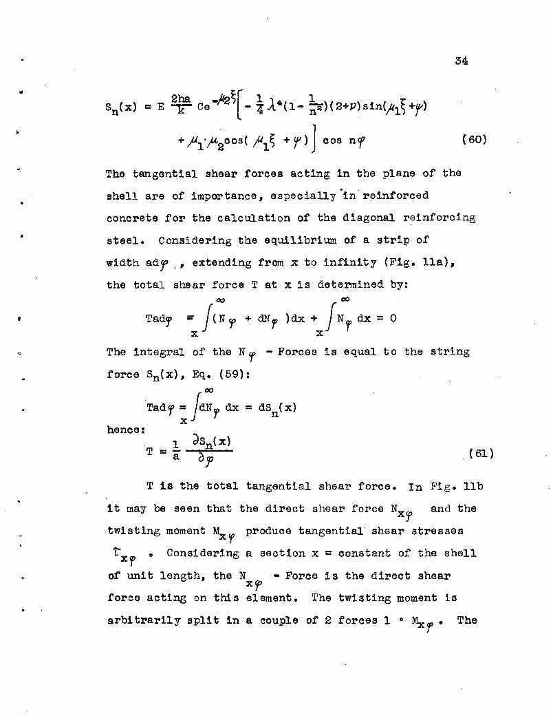
..Sn(X) c E ~ Oe -/12~[-i J..6(1- ~)(2+p)81n(h~+r1
+fl1"}<-2008 ( fl15 + r) ] 008 n'f
34
( 60)
•
.. "
The tangential shear forces acting in the plane of the
shell are of importance, especially "in" reinforced
concrete for the calcUlation of the diagonal r~inforcing
steel. Considering the equilibrium of a strip of
width adr .' extending from x to infinity (Fig. lla),
the total shear force T at x is determined by:00 00
Tadf " Je N 'f' + dNl' )dx + JN'/' dx = 0x x
The integral of the Nf - Forces is equal to the string
force Sn(X), Eq. (59):00
Tad,/, = JdN'J' dx = dsn(xlx
hence:1 dSn(X)
T =a aJ' "(61)
T 1.a the total tangential shear force. In Fig. lIb
it may be seen that the direct shear force NXT and the
twisting moment ~Cf produce tangential shear stresses
LXf
0 Considering a section x = constant of the shell
of unit length, the N - Force is the direct shearxCf
force acting on this element. The twisting moment is
arbitl'srily split in a couple of 2 forces 1 0 Mxr • The

35
total tangential shear force acting on this unit element1
is NXr plus the tangential component i MXf of the 2
forces of tIns couple*:
( 62)
This shear force T has to be used for designing
the diagonal steel in reinforced concrete shells adjacent
to stiffeners. The value of T is determined by Eq. (61)0
3. Effeetive width of an infinitely long cylinder
.' (Poisson's ratio P = 0)
For the symmetrical case it was found that Poisson's
ratio P is of little influence. It can be expected that
this will hold in the general case too. Therefore the
assumption V =0 is made to simplify the folloWing deri-
vations.
The procedure of finding the effective width is
••
the 'same as used in the symmetrical case. In the middle
part of an infinitely long cylinder a string force S is
applied (Fig. lOa). S can have any variation. It is
always possible to present it in form of a Fourier series
(Eqo (51». The effeotive width will be derived for
the nth term of this series. Consider the unit string
force:
( 63)
----------- - - ~ - ~ - - - - - - - ~ - - - -* A similar reasoning is used in deriving the boundary
shear of flat plates, e.g. Ref. (IO), po 90.

•
36
Each of the two parts on both sides of the string will
oarry half of this string force. The continuity for
the 2 parts requires that the slope in x-direction at
x = 0 is zero. By using Table B the 2 conditions take
the form:
.- x =0:2ah 1
Sn( 0) = E k C,Alfl2 cos If cos nr = 2' cos ncrdW
E ~x = - EO sinr00 s nr = 0
,.
The second of these equations requires If= 0 and the
other oonstant of integration beoomes:
1 kC=-----4 Eah 1'11-'2
r= 0
( 64)
It may be mentioned that another boundary condition, axiaJ.
displacement u = 0, was completely disregarded. But the
approximate solution (58) offers only 2 constants of
integration which must be used to fulfill the "essential II
boundary conditions. Ny> is calculated by replacing in
Table B the two constants C and 'f by the
(NfP)x=o = -Lr,u2 + ~ ,;\.4 (l-~»)I 2a}l2t n
expressions (64):
oos nf (65)
The effective width is the ratio of the applied string
toroe S to the direct Force Nf at x = 0 (Eq. (3»:
..
,
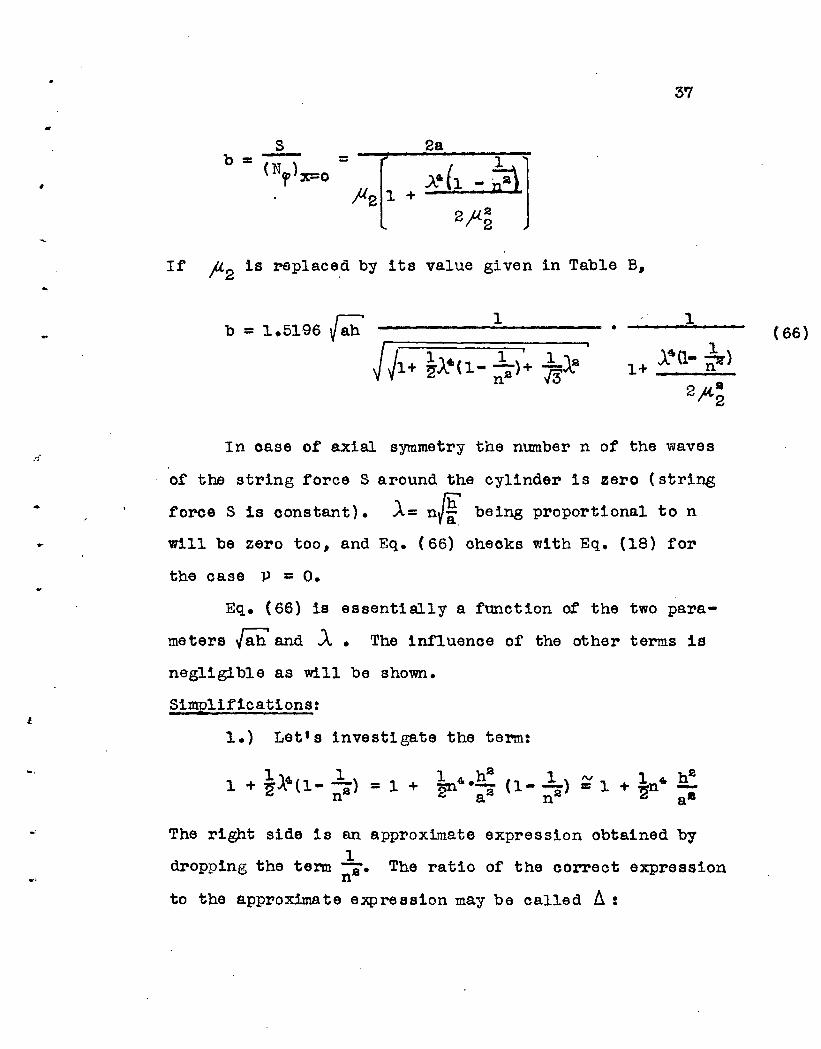
'S7
2a
If #2 is replaced by its value given in Table B,
1-------.;;------. 1( 66)
fj"
...
J.
In case of axial symmetry the number n of the waves
of the string force S around the cylinder is zero (string
force S is constant). .A= n/f. being proportional to n
will be zero too, and Eq. (66) ohecks with Eq. (18) for
the case P = o.
Eq. (66) is essentially a function of the two para
meters Jah' and .A. The influenoe of the other terms is
negligible as will be shown.
Simplifications:
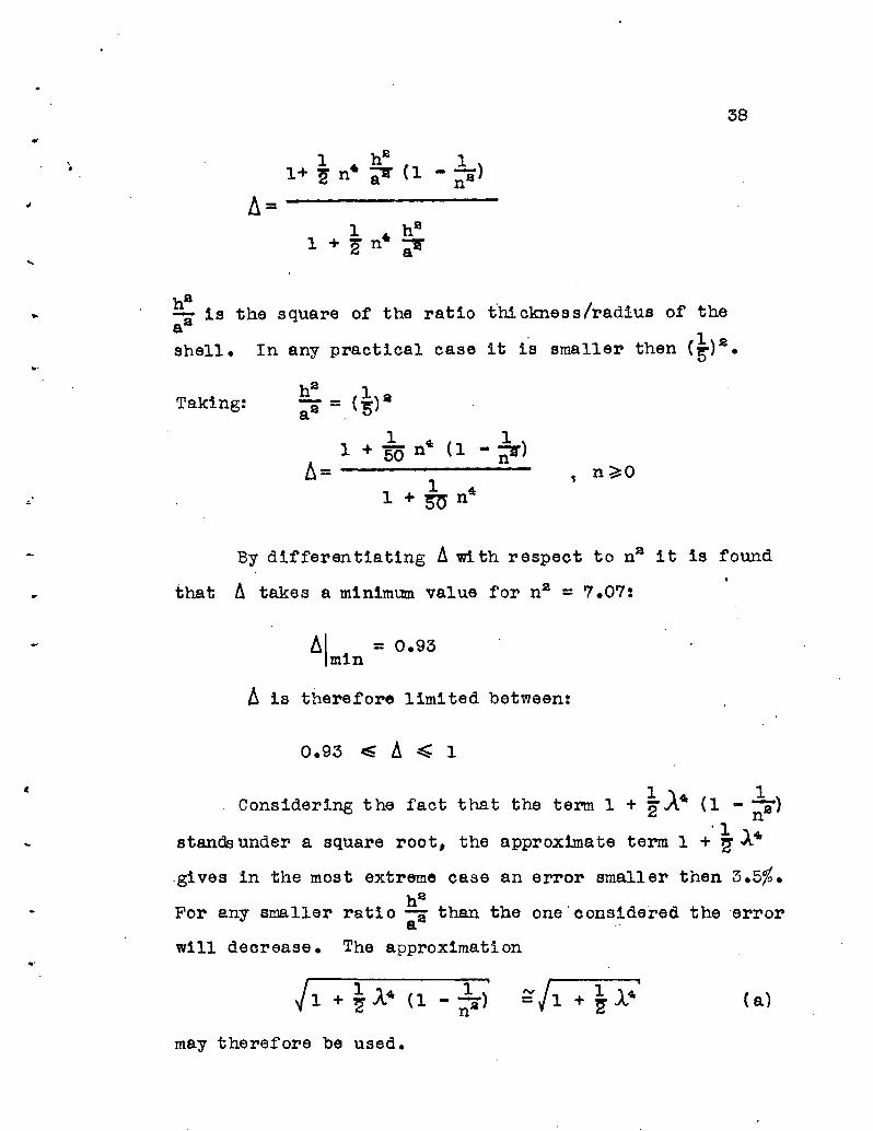
1.) Let's investigate the term:
...
The right side 1s an approximate expression obtained by1
dropping the term -So The ratio of the correct expressionn
to the approximate expression may be called 11:
..,•
38
Taking:
, n~O
By differentiating !J.w:tth respect to n2 it is found
that !J. takes a minimum value for n2 = 7.07:
61 = 0.93min
~ is therefore limited between:
cConsidering the fact that the term 1
stan&under a square root, the approximate
1 "\ 1+ -.1\4t (l --)2 n2
'1term 1 + ~ 14
,gives in the most extreme ease an error smaller then 3.5%.h2
For any smaller ratio :i than the one 'considered the errora
will deorease. The approximation
( a)
may therefore be usedo

39
2.) In the second place the ,magnitude or the term
.'
-------------------
will be analysed. For .A '" 1 it is obviously insignl.f1cant •
In cases where A:> 1 the follo\'l1ing inequality hold:
will oocur.
...
.'
nh 1In practical oases the factor BL ~2· For
nh 1. ~(l-~) nha =~. n ~ 0.225 (-a):a = 0.0563
2#2
The influence of this term on the eff'ectlve Width,
Eq. (66), is ~ 5%. In consequence the simplification
~·(l- J;.)___n_~O (b)
2JA-~
is madeo
In a later equation (Eq. (72» the term
~(l- ~) ,A4(l _~)--......;.,;------------....;.~------
2f1~ 2J3li (J1+ ~ .A·(1- ~l' -7&12)
For A~ 1

40
nhFor the limit of the factor 1L the inequality becomes:
nh 1- -~.a - j::i" 0.555
.'
It will be seen (Eq. (72») that the above term is
multiplied by a rather unimportant factor so that the
simplification
14 (1- ~)----;; 0 (c)
1s justified.
4.) A lastterm CEq. (71» which will be dropped is
--------------------
..
.-
Proceeding as
nb 1a =~:
before,the following inequality
X"(l-~) .__--.;n ~....1 (sh) 2 = 0.1772~1f'2 {2 a
is found:

t
•
41
As an approximation the term can be neglected:
1.A4 (1- i?') ,."____ = 0
2 f!l ft2
Referring to the effective width b as given in
Eq. (66) and introducing the 2 simplifications Ca)
and (b):
( d)
* ( 67)
..-
which is an expression in terms of the two parameters
r;h and ).. only. For the purpose of tabulating Eq. (67)
the following form is chosen:
,
b=Krah' ( 67a)
( 67b)
In Table 2, column ® values of K for different
values of 1 are given. Fig. 16 is the graphical representation
of this Table. Note the rapid de.crease of the effective
width by increasing A.
- - - ~ - - ~ - ~ - - - - - - - - - - - - - - - - - --- -* For design purposes 1.5196 should be replaced by 1.52.

,.
42
The cross bending stress <rx under the rib will
be calcUlated. The bending moment ~ at x = 0 is:
(Table B and Eq. (64»
( 68)
Computing the bending stress Ux and the direct
stress (jr(Eq. (65» the ratio of the two stresses
beoomes:
J.
()x-cr =l' x=o
6Mx- =hNJ'
1
J.·(l- ~)1+ -------,
2ft.;
( 69)
The same simplifications (a) and (b) as for Eq. (66),
are used:
, I~; x=b =1.7321
( 70)
In Table 3 and Fig. l7)Eq. (70) is presented as a
function of .A. •
Finally the string force S~(x), the direct force N1and the bending moment Mx for a d~stance x from an applied

43
(7l )
('72)
( '73)
~os11~] Sn cos n'f'
] Sn cos n,/,
string rorce S = Sn cos nr are calculated. The constants
of integration C and r in Table B are replaced by the
expressions (64):
[
'41 1..1 -fl2S ;'\. (1- n S )
Sn(x) = ~ e -2"a1,,42
'r [ ..\41(1_ ~)N =1.. e -/J2., 0 ~1 (1- ) sin LL~
f 2a 2;«~ / l
1141 (1- ~)
+ "u2{1+ s)2;"2
1 -p. ~rl ~ 1Mx = 4 e 2 fl sin '#1'1 -;;; cos )l1~
( 74)
,
Certain terms, (a),(b),(c) and (d) which were discussed
previously can be neglected. Note that (c) and (d) are
multiplied by sin fl-IS which is zero for the maximum
values of Sn(X) and Nf • If sin~l~ beoomes maximum
these foroes are already greatly damped. By introducing
the simplifications and inserting the values for ~
and JU2' Eq. ('71) and ('73) become:
1 - ).l2~ r:Sn{X) = ~ e . cos)41') . Snocos nf
(75)

• sin Jklt;
44
cos Itl~
• Sn cos n'f (76)
JJ = 0:
I
I
The term )tl~ has the form:
I\~ = i3I*JJ1+ ~)..' -~J.~ • ~ = ;a:' ·~j1+ ~J." - ~2'
The first factor is the well known shell constant ~ defined
by Eq. (10) for the case P = 0
V3(3= yah'
Similarly J'-2~ can be changed to a function of f>x and .A :
jl2~ = <IX>j;jl + ~A.' + *)..~
The 3 equations,(74) to (76),wil1 be written as:
..
1S (x) =~ i 1 ( f!'x, J...) S cos n rpn. n (74a)
(75a)

45
'oW
(76a)
('79 )
..
f
•
I
The functions: i 1 ( ,/jx,.A) :;:: e - }L2S cos 1'1~ (77)
)i S[ If 1 i 1 i
12( f3x,).,) = e- 2 VV 1+ ~.A4 + fi~:a cos 1'1~
+ //1+ ~ )..&' - *12 sinfl~] (78)
1 ( (!>x, A) = e-h~ [ cos fi1~ i
3 jJ1+ ~.A&' + ~J.2
Sinf'l~
are calcUlated in Table 4. (Fig. 18 to 23 are graphs
of the functions).
In the axially s-ymmetrica1 case,.A= 0, Eq. (77)
to (79) coincide with the Eq. (24) to (26).
The total tangential shear T is found by different1ating
the string force Sn(x) with respect to 'f (Eq. (61»:
1 dSn(X) 1 d [1 ]T = i' dCf = i ay; '2 11 ( fx I.A. ) SnCos n r
(80)

'"46
4.) Effective width of a s6mi-1nfinite cylinder:
A unit string force S = 1 cos nf ' rnaking'n complete
cosine-waves around the ciroumference, is applied to the
end of a semi-intinite oylinder. Using Table B the
boundary condi tions are:
x = 0:
E2ah [ 1 1 ]SneO) = --rt C - ~).4(1- ;;:a)sin'f+jl-lf'lz cosr cos nf= 1 oos nf
.'
The condition Mx = 0 furnishes the relations:
, "u1tg r = #2
"u1sin r = -------
/ ~; + )J-~
And the constant C becomes:
k Vr-"p.-r-+-)A.---'~c--- '1
- .2Eah [A,41(1- ~) ]j4. 11. 2 1 n
lr-2 - 2~2
(81 )
( 81)
47
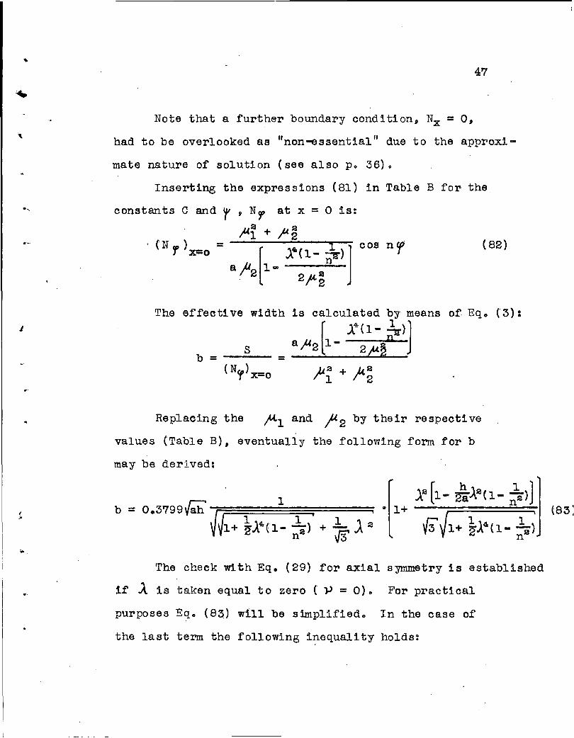
Note that a further boundary condition, Nx = 0,
had to be overlooked as "non-essential" due to the approxi'"
mate nature of solution (see also po 36)0
Inserting the expressions (81) in Table B for the
constants C and
(N fP )J xeo
r ' Nl' at x = 0 is:
,Mi + )I.~= --[--,X....4r-{l-...-~-).....J cos n rt
a h 1-r2 2P2
(82)
The effective widthJ
is calculated by means
[J.4(1- :?T>J
b = __3_ = aft2 1- 2p~n
(Ncr> xeo ~~ + )t~
of. Eq. (3):
Replacing the fC-l and '#2 by their respecti ve
values (Table B). eventually the following form for b
may be derived:
(...
-.
• 1+12 [1- di-~2(1- ~»)
V3 J1+ ~).~(l- ~;
The check with Eq. (29) for axial symmetry is established
if .A is taken equal to zero ( }J = 0) 0 For practi cal
purposes Eq. (83) will be simplified. In the case of
the last term the following inequality holds:

48
\
(84)
It may be remembered that in all actual cases (p. 39):
!!h ~ 1-a . 2
nh 1For a =2": ..!L 'a I ( nh) 2 1
2a .i\. = '2 '2' = 8"
.J
•..
By using the right side of the inequality (84)
instead of the lert one, the effective width will be
smaller. In Chapter IV it will be shown that the simpli
fied formula for b gives the correct limit ror the case
where the radius "au increases to infinity.
Making use of the approximations (84) and (a)
the simplified Eq. (83) is:
b = (85)
For the following form
b=K{;.h (85a)
where: (85b)

\
..
•
•
•
49
the values of K as function of Aare given in Table 2,
column ®. In Fig. 16 the same K-:alues are plotted.
It is remarkable that the effective width stays almost
constant between .A = 0 and J.. = 0.75, whereas the
effective width of the infinitely long cylinder decreases
considerably for the same interval. The physical
explanation for this behavior is the following •. In case
of a constant string force S at the end of a semi-infinitedW
cylinder,the slope ~ is constant around the cylinder.
There is no end-Testraint. rr S varies in n waves arounddw
the circumference,the slope ~ makes the same variation.OW
As ~ changes between positive and negative slopes, the
cylinder as a whole seems to become more and more restrainedOw
against end-rotations -ax. This influence is responsible
for an increase in the effective width. On the other hand
the va.riation of S decreases the effective widt;h. For
the interval .A = 0 to A= 0.75 the t"JO almost compensate
each other. Only for values .A>0.75 does the second
influence become predominant. In case of the infinitelydw
long cylinder the slope ~ is always zero along the line
of the applied string force S. The variation of Sis·
the only influence on the effective width. The latter
starts therefore to decrease L~nediately•

\
.,
t-
J
50
Next, the ratio of the maximum bending stress ~x
to the circumferential direct stress <Sf at x = 0 will be'
derived. The bending moment r~ is (Table B):
Mx = E ~ Cs ""2l;~2sin(,A<l; +1") -1'1cos<;rl;' +1"») cos n'f (86)
By differentia ting ~ with re spect to x t he maximum value
of~~ can be found:
The above expression is equal to zero if the parenthesis
becomes zero:
• Or:
~~ -~~) sin()'l~ +",) + ~:V'2 cos<,.ul~ + r) = 0
tg(l'l~ + r) = 2:1M;}/2 -~l
cos( tt- ~ + If)•
Simple trigonometry gives the two relations:
2Ale2sine f< ~ + r) =
1 fl~ + )(.2
= )t2 ...~ i,Mi + }(2
(87)
If the expressions (87) are inserted in Eq. (86)
the maximum of Mis:x

\51
(88)
Eventually the value of Ncr at x = 0 is found by
replacing the constant of intecration r in Table B by its
value (81). Making use of certain trigonometric relations
.-Nf is:
{N,)x=o = E ~ C,Ml,.u2V}l~ +}4~ cos ne:p
The ratio of the two stresses becomes:
Ux 6Mx = 3a -1'2S- = - , e<rf hNCf h~2V~i + ;U~max
( 89)
max•
•
•
•
and by introducing the values of Pl and ~ 2:
e - ;«2~
=1.2247
V~+ ~).'{l- ;"1'+ ~J.'/l+ ~A'{l- ;;1:Applying simplification (a) the term ~ is dropped:
. -)i2~ n2
cr . ex- = 1.2247 r=;~=;=~==:===:==;:::::::;=~ (91) .
()'/' max I(Jl+ ~). ~ + 7?).8) V1+ ~ J.."
~ must be calculated from Eq. (87). The constant
of integration r in (87) is given in Eq. (8l) as a function
of the ooefficients )A. and hence of the coefficient .A (Table B) 0
The exponent. - j(2~ is a function of J. only. Eqo (91)
is computed in Table 3 for different values of the parameter ~
(see also Fig.l7 ). In the case of 1 = O,Eq. (91) beoomes
"•
..
e-
"
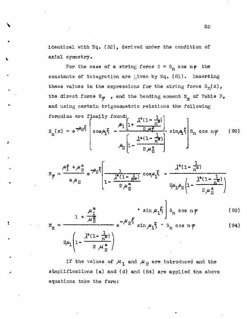
52
identical with Eq. (32), derived under the condition of
axial synnnetry.
For the case of a string force S = Sn c osn 1 the
constants of integration are ~iven by Eq. (81). Inserting
these values in the expressions for the string force Sn(x),
the direct f'orce Nf ' and the bending moment Mx of' Table P,
and using certain trigonometric relations the f'ollowing
formulas are f'inally found: 4( 1 )]r. .x 1-,.S )(1 Ll + n
Sex) = e -}l2 cosJ4.t~ - : 2,Al sinA~ Sn cos nr (92)
n r1
_ J.4(1- ~)J
~[ 2~2
•...
If' the values of' f{ 1 and )l 2 are introduced and the
s~plifications (a) and (d) and (84) are applied the above
equations take the form:
( 93)
(94)

53
"..
(95 )
1 + (96)
3/1+ ~A~'
.~
N - 2.6322f - yah
It was shown on p. 44 that the terms fll~ and )A2~
are functi ons of ( /!Jx) and .A. Therefore Eq. (95) to (97)
are also functions of these two parameters and can be
written:
•
Sn(X) = ~ ( (3x,.A) Sn cos np
2.6322 a'= .r:::;:: 5 2 ( I"'X,A) Sn cos nryah
= 0.75985 5 3( (3 x, A.) Sn cos nf
The .functions se ftx, A}:
( 95a)
( 96a)
(97a.)

54
..
~ ( (3x,J.. ) = e -fl2~ cosh~ ( 98)
s2( (3x,.A) = IJ1+1 I 1 1 e i"2~ cos ,A1~_)..4. + _),ta ( 99)2 {3 )..2
.~ 1+ .3/1+ ~A4ri
• ~ 1 i 1+ _J...4 - -122 {3
s3( {!Jx.,.A)I +~+ i14.· + J:rA:a -1'2'Ej
(100)= e sin )l1"E,2N1+ ~)..' -1s1S'
I
are listed in Table 4 (Fig. 18 to 23)0 If ~= 0, Eq. (98)
to (100) reduce to the a-functions (36) to (38) for the
symmetrical case and in consequence (95a) to (97a) become
ider.tical with (33a) to (35a).
5.) Use of Superposition in General Cases:
Cases where the second boundary of the cylinder
is at a finite distance t from the rib are considered.
'.f
..
•
To the approximate solution (58) another ~erm with anJ"2( 1i - ~ la)
e '-. power (see Eq. 57) must be added to take
into account the boundary conditions at x = t. However,. .
such a solution beccmes so complicated that it is of no
practical value. The principle of superposition gives
the only practical way for a solution of this problem.

..
..
55
The same example as already treated for the case
of axial symmetry ( A = 0) is taken up. (p. 17 and Fig. 6).
A semi-Infinite cylinder has a rib at a distance ~ from
the free edge (see Fi g. 6). Thi s actual case (j) oan be
thought of as a superposition of 3 other cases @, @ and
® already solved. Further explanations of' the procedure
are given on po 18. For a unit string force S = laos nep
the cases ®, ~ and @) give the following direct force Nf
at x =0:
Case@: Eq. (75a)
Case @ Eq. (75a)
{Eq (74a)
Case ® Eq: .( 96a)
(
II-
Case (j) = ® + @ + ® :
0.6580 [(NY') X=O = V~h i 12( o,JJ - i 2 ( 2 ;3 ~ ,.A.)
s2( /37".l >] cos nf
The effective width is (eq. (3»:
(101)
O·
Eq. (102) may be checked for different limiting cases
already solved. If,,8 t =co it l'educe s to the effective
..
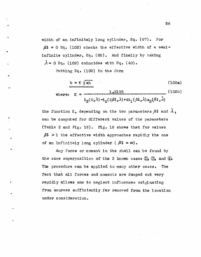
56
width of an infinitely long cylinder, Eq. (67). For
ftl =0 Eq. (102) checks the effective width of a sa.mi
infinite cylinder, Eq. (8S). And finally by taking
..A= 0 Eq. (102) coincides with Eq. (40).
·Putting Eq. (102) in the form
b =K{8:h..where:
(102a)
1.5196 (102b)K ::.
i2(O,A)-i2(2ftt,A)+4il(~t,A)S2{ftt,1)
•
..
the function K, depending on the two parameters ~t and J..,can be computed for different values of the parameters
(Table 2 and Fig. 16). Fig. 16 shows that for values
fit >1 the effective width approaches rapidly the one
of an infinitely long cylinder ( fit :: (0) •
Any force or moment in the shell can be found by
the same superposition of the 3 known cases ® (ID, and ~
Th3 procedure can be applied to many other cases. The
fact that all forces and moments are damped out very
rapidly allows one to neglect influences ori~natlng
from souroes SUfficiently far removed from the location
under consideration.

..
•
57
IV. The Effective Width of Cylindrical Shells in Case
the Radius of the Shell Inoreases to Infinity
1.) The Problem:
The question arises as to what the effective width
of a cylindrical shell becomes if the radius "a" of the
shell approaches infinity. Obviously the axis of the
rib and the middle plane of the shell beoame straight and
the effeotive width should be identical with the
effective width of a flat plate reinforced by a rib (T
Beam). No difficulty exists in prOVing that the differ
ential equations of the shell reduce to the differential"·
equation of a flat plate if the following substitutions
are made: a = 00
• adT = dy
Nevertheless this does not prove that the equations
for the effective width of cylindrical shells derived
in the preVious two chapters will check wit~ those of
the oorresponding T-Beams. For the shell equations
were solved by an approximate procedure (Eq. (58) instead
of Eqo (57») and furthe.r simplifications ({ a) to (d)
and (84») were introduced in order to get expressions
depending on two parameters .A and yah' only. Hence the
limiting process a-+ 00 will be applied to the derived
formUlas for the effective width directly and these

•
-.
..
.'
58
resUlts will be compared to the corresponding equations
of a T-Beam wi th a straight axis •
2.) Effective width of a T-Bemn with a straight axis:
This problem was solved by a number of authors
during the past 3 decades (Refo (1) to (5». Fig. 1
shows a oross section of a T-Beam. The plate is assumed
connected to the rib along the two lines A only. For
any stress in the rib along these lines the stress in
the flange-plate must be the same {continuity conditio~*.
Therefore the plate is under a condition of plane stress
acted upon by boundary forces along the lines A. Airy's
stress function allows a rather simple solution of this
problem.. For the dert vation of the effective width
one of the above mentioned references may be consulted•
It is well known that the effective width of T-Beams
is constant only for the case where the stress along
the connecting lines A varies in the form of a cosine
function. If axial forces are absent this means az
similar variation fbr the bending mCltlent ( (5 = M r). Two
cases~ corresponding to the effective width of an infinitely
long and a semi-infinite cylinder are considered. The
results presented are taken from Girkmann's book (Ref.
(ll) ) •
~ - - - - - - - - - - - ~ - - - - ~ -* For the question if the stresses or the strains mustbe identical see foot-note p. ~.

•
.,
59
a.). T-Beam wi th an lnf'init ely wide nange:
A continuous T-Beam with a nange sufficiently
large to be considered as extending to infinity is
supported by equidistant supports with spans L (Figo l2a)~,
Y is the coordinate in the direction of the rib, x is
taken perpendicular to it. The load acting on the rib
is:
pcp cos ~ yo L
If Poisson's ratio v is assumed to be zero the
effective width of the beam is
4 Lb = 3~ = 0.4244 L (103)
A simple beam of equal span L has the same effective
width if cross-beams at the supports are provided and
are adequate to carry shear forces ~yx.
b.) Beam with an infinitely wide flange on one side:
Differing from the previous case the beam has an
infinitely wide flange on one side only (Fig. J2b). All
other conditions are equal. By neglecting the torsional
stiffenass of the rib the effective width is:
1 Lb =2~ = 0.1592 L (104)
• The only variable in the two equations (103) and

•
•
60
(104) 1s the span L. It is quite obvious that the
effective width increases to infinity if the span L~ 00 •
This fact will be of importance in the following discussion.
Effective width of cylindrical shells for the
~ting case a -. 00:
The string force S = Sn cos n ep and hence the
direct stress ur varies in n complete cosine ""'Waves
around the cylinder (Fig. 13). The length of one half-
wave is L and the angle corresponding to this arc
length Lis:L
oc= aThe number n of complete waves around the cylinder is
hence:1T' 1ra
n =--- =--- (105)OC L
And the parameter ~ (Table B) as a function of the half-
wave lencth L becomes:
(106)
•
Let's now consider the radius "a" increasing to
infinity. During this process the half-wave length L
or the number n of the waves can be kept constant. If
the latter is done the length L becomes infinitely long.
This would then correspond to a T-Beam of infinite span,
a case which certainly does not have any practical meaning.
Therefore the length L will be kept constant.

•
.'.:.
61
a.) Infinitely long cylinder:
The effective width for an infinitely long cylinder
was given in Eq. (67):
b =1.5196 Vah' 1 ,
JJ 1 I I1+-,A.4+-,A2
2 {3
SUbstituting .A = ~ Jah' and rearranging
1.5196 Lb = 7r
Now, in the limit
1
Ny + ~'+ r;as J. ~ 00
( b )a _ 00 = 0.4268 L; ;
(107)
This ohecks within 0.5~ the value of the effective
width of the corresponding T-Beam (Eq. (103» c
b. ) Seml-infinlte cylinder:
The derivation for the effeotive width resulted
b = 0.3799 L
1r /j~
..
in Eq.b(:5~:3799'ab' , 1 J1 + 12]
JJ1+ ~i + ~);l 3~+ ftA~Substl tuting 1 = ~ Vah' and rearranging
+\'+*[1+ 31f1]the limit a--+ 00 (and in consequenoe .1- (XJ ) gives:
(108)

•
.. -
62
The difference between this value and the one of
the corresponding T-Beam (Eq. (104) is 1~4%.
c.) The case of axial symmetry:
The string force Sand henoe the stress <>f are
constant around the cylinder. n, being the number of
waves of S, is obviously zero. The effective width
for an infinitely long and a s~infinite cylinder are
given by Eqo (18) and Eq. (29) respectively. yah'is
the only parameter in these two equations. If the radius
"a" tends to infinity, the effective width becomes
infinitely large •. It should be kept in mind that the
rib gets infinitely long and the shell reinforced by
a rib transforms to a T-Beam with a span L = 00 whose
effective width is equally infinitely large (see EqG (103)
and (104)). The correspondence between the two problems
is established for this special case too.
4.) Conclusions
1. It was shown that the effective width of cylindrical
shells reduces to the effective width of the corresponding
T-Be~ns with a straight axis if the radius of the shell
is inoreased to infinity. The check 1s complete from the
practical point of view (differences of 0.5% and 1.4%),
but it is not a mathematically exact one. This is to be

•
•
to
63
expected as an approximate solution (Eqo {58)) was used
for the derivation of the effective width of cylindrical
shells.
2. The close correspondence established between• II IIthe two problems for the 11mi tJ.ng case a = co may be con-
sidered as a justification for the use of the approximate
solution Eq. (58).
3. The derived formulas for the effective width
are notlimi ted by a certain value of the radius "a".,
They are based on the general principles of the theory
of elasticity. The stabllity* of the shell and of the
combinati~n of the shell and the rib gives an upper
limit, a problem which exists equally for the effective
width of the T-Beam.
Vo General Remarks on the Application of the Effective
Width
1.) Symmetrical case:
The effective width b depends on the dimensions
and the material (Poisson's ratio V ) of the shell only.
It can be easily determined from the for.mulas or tables.
- - - - - - - - - - - - - - - - - - - - - - - - - - - ~ -.. See Appendix for a resume' of this problem.

....
.'.
64
The errective section consists or the rib and the
erfective width or the shell as a flange. Area and moment
of inertia or this section can be computed. The rib
stre sses and the deformati on of the rib calculate d for
this effeotive section are the actual stresses and
deformation. The string farce S acting an the shell
is eiven by Eq. (4):
S = bh . <rA
where O'A is the stress in the rib along the connecting
lines A (Fig. 4). The direct force N~ and the bending
moment M are readily determined by use of the i- andxs- functions given in Table 4.
2.) General case
a.) Statically determinate case:
No use of deformations need be made to find the
va.riations of the stress u A (not magnitude) along the
connecting lines A between rib and shell (Fig. 4).
Hence the expansion of this stress in a Fourier series
is possible except for a constant multiplier. The
effective width for each term of the series can be
calcUlated and their superposition gives the actual
effective width of the shell for the ca.se under consideration •
Computing the area and moment of inertia of the
effective section the stresses in the rib can be determined.

•
J
65
Eventually the string force S,acting between the rib and
the shell ~ and the N~ , Mx and T in the shell are found ..
b.) Statically indeterminate case:
The stress distribution depends on the deformation
of the structure. In this case a certain variation of
the stress must be assume d in order to calculate the
different terms of the Fourier expansion. Note that only'•the yariation, not the magnitUde of the stress distribution,
must be assumed for calculating the effeotive width. The
stresses in the ribs and the forces in the shell are
found by the above explained procedure.
Probably the calcUlated stress ~A along the connecting
lines of rib and shell (Fig. 4) differs fram the assumed
variation. The,refore the whole procedure must be repeated
until a SUfficiently close correspondance between the
assumed and the calcUlated stress distribution is found.
'Aotual applications show that it is rather easy to make
a first assumption which does not require any repetition
of the procedure.. It should be noted that the effective
width is not influenced to a great extent by a small
change of the assumed stress distribution. The area and
moment of inertia of the effective section change much
less beoause the effective width of the shell makes up
the flange of this CrosS section only.

..
..
.'
66
Appendix
Limi tations of the Effeotive Width by Stability
1.) T-Beam with Straight Axis:
It is conceivable that the flanges of aT-Beam,.as shown in Fig. 1, may buckle under a certain stress
fSy in direction of the r.ib (y~irection). The question
arises for what magnitude of the stress uy this limit
will be reaohed and what will be the effeotive width of
the flange in the buckled state.
Th. v. Karman solved the somewhat similar probl~
of the effective width of a flat panel, simply supported,
under uniform compression in the buckled state (Ref. (15».
In a T-Beam the stress c:r will vary in general as ay
function of both coordinates x and y (Fig. 24). Therefore
shear stresses ~xy will be present in the flange too.
Over a length t (half wave length of the buckles in y
direction, equal to the effeotive width b as will be
shown later on) the stress Uy will be assumed as
oonstant. Furthermore the distribution of the ~y in the
x-direotion (perpendicular to the rib) will be assumed
constant over the effective width b, and equal to the
normal stress uA acting along the connecting line between
the rib and the flangeo Outside of the effective width

• 67
() is considered to be zero. The buckled middle surfacey
of the flange over the effective width b (see Figo 24)
is assumed to have a deflection:
..1rx 1t'v
w = Wo sin - sin ..-...b ~
(lOg)
where b is the total effective width fl/2 b on ,each side
of the rib) and ~. is the half-wave length of the buckles
in the direction of the rib. Eq. (lOg) ~plies the,
following boundary conditions for the buckled flange:
x= 0 • w = 0•
'02WMx= ~X2 = 0
+ b dWx = • ai= 0•-2
y =0 or 'l,: w = 0
/..The
effective
horizontal
action of the entire flange outside of the
width ~ ~ consists merely in providing theb
tangent at x = ~ ~. The torsional stiffeness
.'
of the rib is neglected, the moment Y-x at x = 0 being
zero.
For the buckled state the differential equation of
an initially flat sheet under a uniform compression force

• 68
Vlhere:EhB
D =-----12(1- p 2)
(110)
Replaoing W by its assumed value (109) and dividing
1rx .r.zthe result by wo·sin ~'sin ~ Eq. (110) beoomes:
7r4 11"" 1r 4r NA ?ria""'-+2-+-:---
b 4r b 2 Z2 t 4 D 18
And by introducing the val ues for D and NA
uA -;r la h2 ~ 1E = 12(1-p Si ) (i;'2 + 'i)2 (Ill)
Eq. (Ill) has its-'minimum if Z = b which can be
found by differentiation.
The effective width b therefore is
(112)
Eq. (112) gives the effective vrldth of a T-Beam with
large flang"6s after local buckling of the flanges took
placeo b is proportional to the thickness h of the flange
and depends furthermore on the modulus of Elasticity E,
the stress uA along the connecting line of the nange
and the rib and Poisson's ratio V of the material.

•
,
69
In t he case of a beam wi th a large flange on one
side only (Fig. 12b) an analysis similar to the one above
gives an effective width b half of the one of Eq. (112):
(113)
(
Consider now the caae where uA approaches the
yield stress uyle1d of mild steel. Due to the sharp
knee of the stress-strain curve it will be a very good
approximationm use the modulUs of the elastic part E
and the yield stress <S'"yieldo By taking:
E = 30 • 106
1b/in2
()yie1d = 33 • 103 1 b/in2
l> =0.3
the effective width b is:
(112) 30 • 103
33= 57.33 h (114)
(113) (115)
•
Eq. (114) holds for a ~-Beam with large flanges on both
sides (Fig. 12a). In case of a beam with a flange on one
side only, Eq. (115) has to be used (Fig. l2b) •

'..
•
..
..-
70
In a practical problem the effeotive width will be .
oalculated first by means of Eqo (103) or (104) respectively,
which were derived under the assumption that the equilibrium
of the flange is a stable one. Then the derived stress
c:r along the cormecting line ~ the rib and the flangeA
is introduced in Eq. (112) or (113) respectively. If
(112) or (113) furnishes an effective width smaller than
the one derived by (103) or (104) it indicates that the
flanges will buckle. Therefore the effective width of
Eq. (112) or (113) must be used in the calculations.
For structural steel the flanges 'are in a stable
equilibrium, if the effective width b <: 57 h or b <: 28 h
for a T-Beam or a beam with a nan~ on one side only,
provided the yield stress is not exceeded. (Compare Eq.
(114) and (115').'
It may be pointed out that the' above equations are
limited by the s impllfying assumpti ons made for their
derivation.
2.) Cl1indrical Shell:
In deriving the effective width of a cylindrical
shell the influence of the tangential shear forces NxCf
and N 1 x (problem of shear lag in box g~rders) and of
the radial deflection w of the shell due to the direct
forces Nf was considered. Therefore by increasing the
load from an ini tial zero load the radial deflection w
..
•
71
of the shell rela tive to the rib will increase proportion
ally, and to each load corresponds a definite state of
equilibrium. On the other hand for the fiat nange of
aT-Beam it was shown that for a certain stress (S"A in
the flange a point of bifurcation of the equilibrium
is found.
Let's consider a cylindrical shell of thickness h
and a very large radius I~I stiffened by a rib in circum
ferential direction. By loadine up the rib a certain
circumferential stress ~A along the connecting line
of the rib and the shell may be reaohed for which the
equilibrium of the shell may beoome indifferent and more
than one state of equilibrium can be possible. The shell
will buokle. The solution of this stability problem is
certainly more involved than the on8 solved preViously
for the flange of a T-Beam. No attempt is made to derive
a solution. But certain concl usions form the T-Beam·
solution may be drawn to have at least a qualitative
insight in this problem.
Very probably the strain energy of the shell reqUired
to reach the state of indifferent equilibrium will be
higher than the strain energy of the corresponding T-Beam
(shell and nanga of T-Beam are assumed to have the same
thickness h). A shell with a very small radius "a" will
not reach buokling before yielding is developed. On the other

..
ff
72
hand a T-Beam can buckle elast ically. Thi s seems to
indicate that the stability limit for the shell (curved•
T-Beam) occurs for a higher stress GA along the connecting
line of the shell and the rib than the stress of the
corresponding T-Beam wi th a straight ax1 so It is therefore
believed to be safe to use the Eq. (112) or (113) for
the Case of the effective width of a cylindrical shell
too. The problem of stability for the shell arises
only for large radii "a" where the axis of the rib can
be considered as almost straight, especially considering
the relative short half-wave length ~ of the buckles.
3.) Recoi!rllsndations for' Further Studies:
To the author no tests on the stability of the
flanges of T-Beams are knOVIn. A T-Beam differs .from
the usually tested flat panels with stiffeners under a
constant end compression. For the stresses induced in
the flange are originated by shear forces along the conneoting
line of the riband the flange, the direct stresses ~y in
direotion of the rib are fUnctions of the coordinate x
and y and the flange will have in general stresses <r'x'
~y and Lxy (Fig. 24). Tests on T-Beams with a straight
axis should be made in order to have experimental resul ta
. to compare vJi th the Eq. (112) and (113).

..
f
•
...
..
•
73
Experiments on T-Beams wi th a curved axis or on
cylindrical shells reinforced by ribs in circumferential
direotion under loads 'applied to the ribs are necessary
to find the stability limit of such types of structures~
A theoretical stUdy parallelinG the tests is required
to find a rational design base •

•
..
,
•.
....
•
Tables 1 to 4
(Pages 75 to 83)
74

t .
..
J
TABLE 1
Functions c( /3t) and f( "st)for different values of theparameter §'t
For Graphical representation sea Fig. 14 and 15.
75
® ® ® ®
..
..
..
ftt C1. c2 c 3 c4 t 1 t 2 f 3
0 0.3799 o. o. O. O. O. O.
.2 .5635 .3038 .3038 .0392 .0781. .0693 .0461
.4 .8044 .6048 .6065 .0759 .3343 .2751 .1841
.6 1.0622 .8891 .9014 .1138 07385 .6012 .4096
.8 1.2706 1.1277 101736 .1514 1.1645 .9927 .7062
1.2 1.4100 1.3686 1.5573 .2236 1.6162 1.5987 1.3510
1.6 1.4565 1.3938 1.6564 .2835 1.7317 1.7316 1.7486
2.0 1.4633 1.4071 1.6015 .3339 1.7109 1.6902 1.8310
2.4 1.4821 1.4448 1.5428 .3620 1.7019 1.6722 1.7898.2.8 1.4972 1.4819 1.5181 .3748 1.7097 1.6874 1.7484
3.2 1.5122 1.5053 1.5140 .3788 1.7198 1.7094 1.7307
1.5196 1.5196 1.5196 .3799 1.7321 1.7321 1.7321
Eq. ( 40b) ( 44b) (47b) (50b) (42b) (45b) (48b)
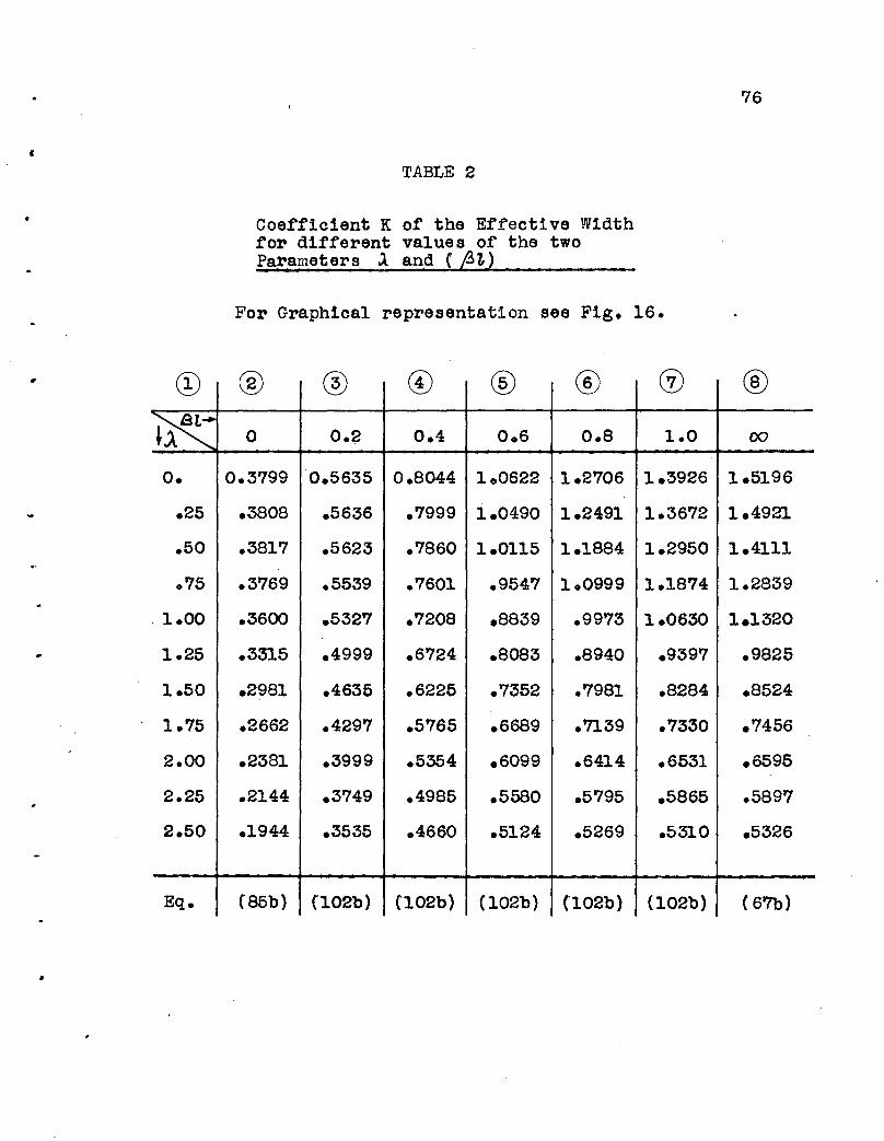
«
•
TABLE 2
Coefficient K of the Effective Widthfor different values of the twoParameters land ( L3~)
For Graphical representation see Fig. 16.
76
® ® ® ®
•
~~1 0 O.~ 0.4 006 0.8 1.0 00
O. 0.3799 0.5635 0.8044 100622 1.2706 1.3926 1.5196
.25 .3808 .5636 .7999 1.0490 1.2491 1.3672 1.4921
.50 .3817 .5623 .7860 1.0115 1.1884 1.2950 1.4111
075 .3769 .5539 .7601 .9547 1.0999 1.1874 1.2839
.1.00 .3600 .5327 .7208 .8839 .9973 1.0630 1.1320
1.25 .3315 .4999 .6724 .8083 .8940 .9397 .9825
1.50 .2981 .4635 .6225 .7352 .7981 .8284 .8524
1.75 .2662 .4297 .5765 .6689 .7139 .7330 .7456
2.00 .2381 .3999 .5354 .6099 .6414 .6531 .6595
2.25 .2144 .3749 .4985 .5580 .5795 .5865 .5897
2.50 .1944 .3535 .4660 .5124 .5269 .5310 .5326
Eq • (85b) (102b) {102b) (102b) (102b) (102b) ( 67b)

TABLE 3
For graphioal representation see Fig.17.
77
..
00
.25
.50
.75
1000
1.25
1.50
1.75
2.00
2.25
2.50
Eq.
Int1n1tely longoy11nder
Ux-Ucr %=0
1.7321
1.6702
1.4933
1.2363
.9611
.7240
.5450
.4170
.3262
.2609
.2128
(70)
Semi -1nt1n1t ecy11nder
Ux-CJr max
0.5583
.5431
.4915
.3994
.3046
.2148
.1495
.1061
.0778
.0588
00458
(9l )
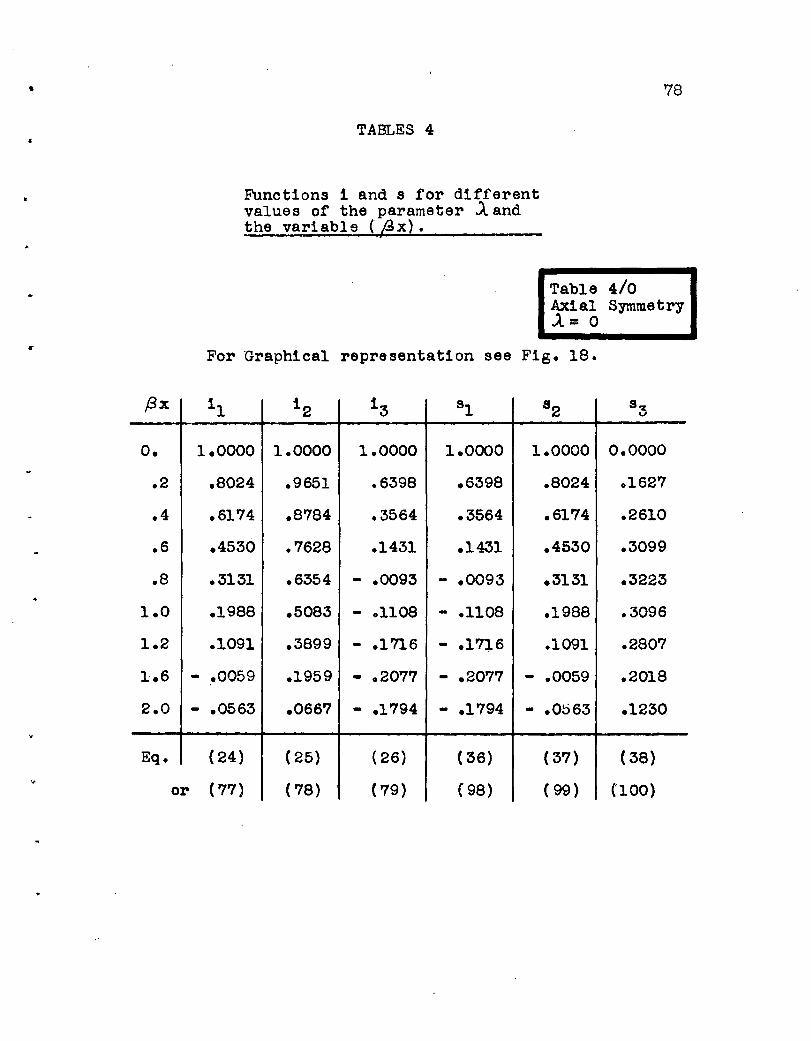
,
•
..
78
TABLES 4
Funotions i and s for differentvalue s of the parameter J.. andthe variable (~x).
I
Table 4/0Axial SymmetryJ.. = 0
For Graphioal representation see Fig. 18.
f3x 11 12 13 sl 8 2 8 3
o. 1.0000 1.0000 1.0000 1.0000 1.0000 0.0000
.2 .8024 .9651 .6398 .6398 .8024 .1627
.4 .6174 .8784 .3564 .3564 .6174 .2610
.6 .4530 .7628 .1431 .1431 .4530 .3099
.8 .3131 .6354 - .0093 - .0093 .3131 .3223
1.0 .1988 .5083 - .1108 - .1108 .1988 .3096
1.2 .1091 .3899 - .1716 - .1716 .1091 .2807
1.6 - ~0059 .1959 - .2077 - .2077 - .0059 .2018
2.0 - .0563 .0667 - .1794 - .1794 - .0063 .1230
Eq. (24) ( 25) ( 26) ( 36) ( 37) (38)
or (77) ( 78) ( 79) (98) (99) (100)

,
1
..
.'
..
79
Table 4/0.25-A =0.25
fJx i 1 12 13 ~ 8 2 8 3
a. 1.0000 1.0184 0.9819 1.0000 0.9976 0.0000
.2 .8000 09710 .6235 .6464 .7981 .1564
.4 .6147 .8762 .3443 .3690 .6132 .2504
.6 .4512 .7558 .1359 01602 .4501 .2965
.8 .3129 .6264 - .0115 .0108 03121 .3078
1.0 .2005 .4993 - .1090 - .0893 .2000 .2952
•3820.
1.2 .1125 - .1666 - .1501 .1122 .2675
1.6 - .0002 .1924 - .1997 - .1892 - .0002 .1926
2.0 -.0500 .0673 - .1717 - .1662 - .0499 .1183
Eq • (77) ( 78) (79) (98) ( 99) (100)
For graphical representationsee Fig. 19.
Table 4/0.501 = 0.50
..
(3x 11 12 13 ~ 8 2 8 3
o. 1.0000 1.0770 0.9285 1.0000 0.9953 0.0000
.2 .7922 .9928 .5752 .6625 .7885 .1403
.4 .6052 .8732 .3079 .3997 .6024 .2224
.6 .4440 .7379 .1141 .2027 .4419 .2610
.8 .• 3101 .6018 - .0205 .0643 .3086 .2692
1.0 .2027 .4738 - .1050 - .0345 .2017 .2567
1.2 .1196 .3595 - .1537 - .0946 .1190 .2319
1.6 .0138 .1810 - .1779 - .1404 .0137 .1670
2.0 - .0338 .0672 - .1503 - .1300 - .0336 c1041
Eq. ( 77) ( 78) ( 79) ( 98) ( 99) (100)

Table 4/0.75.A =0.75
80
...
f3x 11 12 13 ~ 82 83
o. 1.0000 1.1836 0.8449 1.0000 1.0080 0.0000
.2 .7774 1.0380 .4997 .6777 .7836 .1206
.4 .5858 .8770 .2507 .4308 .5905 .1876
.6 .4265 .7166 .0786 .2476 .4299 .2165
.8 .2983 .5680 - .0340 .1167 .3007 .2197
1.0 .1982 .4305 - .1019 .0272 .1998 .2068
1 0 2 .1222 .3253 - .1372 - .0304 .1232 .1847
1.6 .0275 .1608 - .1474 - .0809 .0277 .1311
2.0 - .0152 .0622 - .1195 - .0829 - .0153 .0820
Eq. ( 77) ( 78) (79) (98) (99 ) (100)
For graphical representationsee Fig. 20.
Table 4/1.00.A =1.00
.'
•
;"
f,x 11 12 .13 st 82 8 3
o. 1.0000 1.3424 0.7449 1.0000 '1.0552 0.0000
.2 .7546 1.1116 .4100 .6812 .7963 .1035
.4 .5545 .8932 .1833 .4437 .5851 .1562
.6 .3958 .6983 .0370 .2714 .4176 .1753
.8 .2733 .5320 - .0512 .1504 .2884 .1732
1.0 .1811 .3946 - .0991 .0683 .1911 .1590
102 .1136 .2846 ....1194 .0152 .1199 .1387
1.6 .0326 .1340 - .1150 - .0345 .0344 .0946
2.0 - .0026 .0514 - .0866 - .0435 - .0027 .0576
Eq. (77) ( 78) ( 79) ( 98) ( 99) (100)
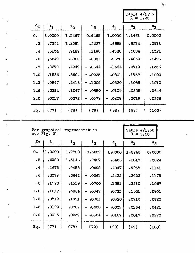
Table 4/1.25A = 1.25
81
,f3x '1 12 13 ~ 82 831
o. 1.0000 1.5467 0.6465 1.0000 1.1461 0.0000
.2 .7254 1.2081 .3227 .6698 .8314 .0911
.4 .5134 .9189 .1198 .4328 .5884 .1321
.6 .3542 .6825 .0001 .2672 .4059 .1425
.8 .2372 .4949 - .0644 .1544 .2719 01356
1.0 .1533 .3504 - .0935 '.0801 .1757 .1200
1.2 .0947 .2418 - .1009 .0330 01085 01010
1.6 .0284 .1047 - .0850 - .0109 .0325 .0644
2.0 .0017 .0372 - .0579 - .0208 .0019 .0368
Eq. (77) ( 78) ( 79) ( 98) ( 99) (100)
For graphical representationsee Fig. 21
Table 4/1.50.A =1.50
•
x 11
12 13 81 82 83
o. 1.0000 1.7828 0.5609 1.0000 1.2742 0.0000
.2 .6920 1.3146 .2487 .6466 .8817 .0824
.4 04675 .9455 .0692 .4047 .5957 .1141
.6 .3079 .6642 - .0261 .2432 .3923 .1175
.8 .1970 .4559 - .0700 .1382 .2510 .1067
1.0 .1217 .3054 - .0842 .0721 .1551 .0901
1.2 .0719 .1991 - .0821 .0320 .0916 .0723
1.6 .0199 .0767 - .0600 - .0032 .0254 .0421
2.0 .0013 .0239 - .0364 - .0107 .0017 .0220
Eq. ( 77) (78) ( 79) (98) '( 99) (100)

82
Table 4/1.75.A =1.75
{3x ~ 12 13 81 82 S3
o. 1.0000 2.0380 0.4907 1.0000 1.4272 0.0000
.2 .6570 1.4207 .1899 .6169 .9377 .0761
.4 .4209 .9652 .0323 .3682 .6007 .1000
.6 .2623 .6396 - .0415 .2107 .3744 .0977
.8 .1585 .4133 - .0689 .1141 .2262 .0842
1.0 .0921 .2602 - .0720 .0566 .1314 .0673
1.2 .0509 .1591 - .0643 .0239 .0726 .0512
1.6 .0119 .0529 - .0407 - .0022 .0170 .0267
2.0 .0000 .0134 - .0216 - .0066 .0000 .0124
Eq. ( 77) ( 78) ( 79) ( 98) ( 99) (100)
For graphical representationsee F1g. 22
Table 4/2.00J. =2.00
)
(ax 11 12 1 3 ~ 82 83
o. 1.0000 2.3042 0.4340 1.0000 1.5952 0.0000
.2 .6221 1 0 5201 .1444 .5845 .9924 .0709
.4 .3760 .9742 .0070 .3292 .5998 .0883
.6 .2205 .6077 - .0487 .1772 .3517 .0816
.8 .1246 .3682 - .0634 .0894 .1988 .0664
1.0 .0673 .2162 - .0596 .0407 .1074 .0501
1.2 .0342 .1228 - .0489 .0151 .0546 .0360
1.6 .0060 .0340 - .0267 - .0028 .0096 .0166
2.0 - .0009 .0062 - .0124 - .0045 - .0014 .0068
Eq. ( 77) ( 78) ( 79) (98) ( 99) (100
~..
".
..

Table 4/2.25J. = 2025
83
#x 11 12 1 3 81 82 83
o. 1.0000 2.5767 0.3881 1.0000 1.7721 0.0000
.2 .5879 1.6091 .1093 .5512 1.0418 .0665
.4 .3344 .9725 - .0099 .2914 .5926 .0782
.6 .1834 .5692 - .0507 .1458 .3250 .0682
.8 .0963 .3209 - .0561 .0675 '.1707 .0523
1.0 .0478 .1758 - .0478 .0273 .0847 .0371
1.2 .0218 .0918 - .0363 .0081 .0386 .0250
106 .0023 .0204 - .0171 - .0032 .0041 .01.01
2.0 - .0012 .0019 - .0068 - .0032 - .0021 .0036
Eq. (77) ( 78) ( 79) ( 98) (99) (100)
For graphical representationsee Fig. 23
Table 4/2.50
.A = 2.50
•
. fJx 11 12 13 S:1. 82 83
o. 1.0000 2.8530 0.3505 1.0000 1.9544 0.0000
.2 .5548 1.6865 .0821 .5185 1.0843 .0625
.4 .2961 .9598 - .0208 .2558 05787 .0694
.6 .1513 .5262 - .0493 .1182 .2957 .0570
08 .0733 .2773 - .0481 .0495 .1433 .0411
1.0 .0331 .1398 - .0377 .0171 .0647 .0274
1.2 .0132 00664 - .0263 .0032 .0258 .0173
1.6 .0004 .0109 - .0107 - .0031 .0008 .0060
2.0 - .0011 - .0003 - 00036 - .0022 - .0021 .0018
Eq. ( 77) ( 78) (79) ( 98) (99) (100)

....
..
'j,
Figures 1 to 24
(Pages 85 to 101)
84

85
Imaginary stress distribution> '
Actual stress distributionI . I
--b -.j I---b~2 . 2 J
I I-~---l
I I I III I I I III I ! I II I I I I
. A '---- Flange" (flat plate)
T-Beam Fig. '"
:;;
Rib
i5he"h
--_.~. --------- ----------_ .. _-- .. -
----:: -oj-------:: ==r~-------::----_. ----- .~---
.-
..
Circular cylindrical shell
reinforced by ribs.Fig. 2

.-----------------~--- -
86
r String -
..
a--u--------
-------- ---------
IIIL _
Effective width of cylindrical shells
Fig. 3 .
- Rib
17I
-- zb
- n
A
Stressesf -~
v;~
- Center line
Fig. 4
M
s

a) Infinitely long cylinder
87
b) Semi -Infinitecylinder
Force S =1o
..
c) w ...... x
k:/v
" ~aJ>
Displacements
Fig. 5
Of- -xex) =_f-r----__----- -f ---I
1-1 --:.. 1-4I , I
So! I Ir I I
Case CD = @+@+@
Case ®
oo~{-·- ------ ---i~-;)ttj(--:--t~ co Case ®
: So(l(: -SoI
00-
Fig. 6

..
..
/
c.)
III
____ _"_ J
III
--- -----J
J[-,-""I . \I, . )-Detoi I
" /........ -
r--l'-i
88
Fig. 7
r---~ f=-_=-::::_:-=-==-=:-:.=-==1- - - -- - - - - - 1---=---1......,,·-= --rI . h aI !
---J---- _i.
I .---- --- -------- ..- - - -- - -- ..- - - - -- _.-
.Oi----x-2l----Pi~~-- 2 'l --.., ;.4-- 2l--'" ,-4-- 21- Fig. 8
T h
TII
aI
-------r--- L
---------'-
O!-.---·~X
---1I .
I.,,1
I
Fig. 9
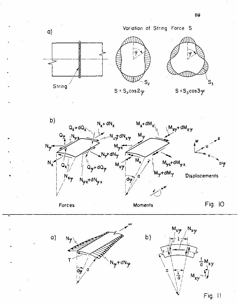
a)
89
Variation of String Force S
..
String /
b)
Forces
a)
Moments
b)
Displacements
Fig. 10
Fig. II

90
I, !
---"1---- -"~I ,,'- - --- TrjTITITfrrrrqrfrj"ll'rTfrr- ,Ll.tlU_,---. I '! I! . i' I' i I I! i II " !, I " '
I 0 I AI I
F"t-Y~l:yt ",'''2',u 'r"};;
Section A - A :
- X_;.__0_1 ~,O-=- Xa)-E. ,. ,. ,. " '" " " -' _ { . 2 -', '''." 2 -' , . ;p
b)
..Fig: 12
"
..
Middle surface
of the shellString force S =Sncos nCf
•
Fig. 13

Kl:u,.F£L £ .ESSUI co.. N. Y. NO. ],59·5
• 10 X 10 to Q.. 1uIb..WADI IH U. S. A.
-------------

K ""I:L" E IE" eo., N." NO 359-5
10 X 10 '" .-.\.uD"''''Of 1M U. ,. A.
•

K.UFFaL " IfSS". co .• N. Y. NO. 35.·5
10 X 1010 ..... LuLw.MII IN U. S. A.
•
I ' ~ I++-r--H-! I i I I : 1......-
.~ i : I I I I I 1+!-1
+-fOol I' 1IIIIIIIImm~r-- 'Tn I~ tttt-t-}i'J .. ~tTt r+'
I :-T ,-'-,I t- --lTi I"r -J TTT~' i-"
-.--+- f-1:;1:
..l....l-+-+..++-H-I+-H I I I • : -l-;
<0~
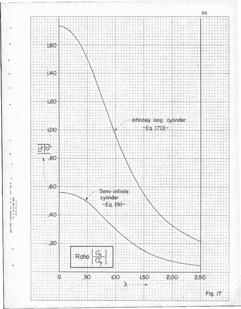
..
WI...."o%
~i% •. ~3 II.0:-
::x..",0.~..
oJ
"'...."..
94

III
~l'l
.;Z
95


•..""ciz
~lz •.~3 II
o,,w:: x
...w....::>
~ 97
I
-~
It -.-;......~1~+__1-
I T,
I -r
L
T

L
........ciz
~]z ..-~
ci su ...-~ )(
..oJ......:>
98
I
--H--+i-i-H-++++-H-(
I ,-r-r- +~t- ~ < ......- , H---r--+- .... - '- 4- , _~ 1-,-++_+,+-1 -'--ri+ -H-t-+...,-J....-j-....l-j
..,-t l I ,T-' 1-'- -t-r ~ .... ,- ,... ,il A"T i.JUI I ~-.-j·~H'-+'-+i-'i--':i!1H-T-r-<-4---f-!-+++--j-,'-'4-T....j.....;.. -r .Lt--f"F-f'f1-,"H-+"'H-+++-+-+ r-r-T "
Ij± ' I i' I - I I' II I-=r;--r-r-t i , , • ~ I I I ~I t-+I+++-H-r-t-~t-i-++,-H-+-+-+-+~ r +-......" ' 1t-t- +4-,-r-r - ,I -w 'I I , -~·r-+-++·-+-+-+-~'f""'"-, i I I Ii' I ----;--1""11 r-:- ,I I I , ..,.. _ ,- f- f- -i-"-+l--H-i-H--H--+--1'-t-t-+--:---.-i-'-' I =f7i'
I I .....,-;--r-,. -~ r- :f'--'- I .-I::p" -t. =+- l-L,_-l- ,I I ' ;-_,.L +-- ~ 1_ ~_U... - ......... , ~,~-' iI --r-r- I 11 I' ! I I!

........oz
~1z •. ~gs
o.-::x"s..~w~
~
:>~.

100
I
1 J ! f-
'Jz •. ~~ s
C>
"":x.... ~...........~.."
t-+-+-r. !-'-'r+ ---r-U--l-J-++-+--H+-~+++-j-+-H-+-t--H~-+-l1+-;'.-i-l-++-+++-H-i-H-++-H-
~~ """"'-+--+--++--'-'1-,--1-+--'-+ +-+-+-+-++1 ++-++t-+-+-+-I -t-+-+-+-H-+-+-+-+-II-+-++-Hf-+-++-HH-+-t-f-H--
'F \\ \ .... ..J ~ - A . -4-~ -I-'- H-t-H-+'-H'-+++-hrr-h-l-h-++--,-H--H-t-t-I +-t--j
I-H-++-r-t-.+-+-~ ~~\ 1:0 '-' _. - r .-t-t.~ ~-t-t--!II-H---+-+-;-;_--<-"-+++1--+-t-+-+-t-'I-H--+-r--+-t-++-j-'+1
+-l---i--+-+-t' .l- ~ -L ,i\. / ~ "1-~ ~t:l' i ~r-1---1.'-4--'-I---l I"h H-+-+++-H-H-t-H-++,++++--Hi .:0 "1-+ k\ I/: -74%-__ 1-1- , i-r+-H-+-t+-l-J-+t+..--I---f-f-+-H---f-+-t--+--'H-++-I-H-t-I
H-,-'--,-'-H-r-t-'+-+--1 -:--r+\~-LL.' _. .~... ..+- -+-+-+-+-r-t-t-II-t-+-+-t-H--T-+-r-t --H-t-.t-+-+-t-t--i1--I,-++-1-1--1-+-1-+! "".--+-r- -- J- r y-t-./-4--I-f,--i-.;....r"~'~-t-t-+-l---f-+-,-c---+-t-H ~--H-+t+++ ..,.----j-r+ H-+-t-++-t--i1-t-~--t-!-t-bt--4--f~I--......- 'I. " Y "Iii. __......+-r-H--+-+-+-l-t-~ , I

101
•
'Section A-A '
. : : I I I ~ .' i·: _."1 II i , , , , I . I I ' :, "I ',# .! 'j' i ! i i .~.: : '.I II I I i I I ' , : ; i; 1:11""", .j
~--l ------- .....,/~---''> _, ...o",}\
{., ,- -">-~/ \ -'--Buckled Middle Surface
of the Flange
Section B-B
wx
-,'--jYAt_
Fig. 24

Notat1ons
L1st of References
Vita
(Pages 103 to 110)
102

lOS
NOTATIONS
Roman Alphabet
a
A
b
B
01 ( P 7,)
02 ( ,8 7, )
0S( (3t)
04( f3'£)
c
Cl to Cs0"1' IT2
D
e
E
f l ( ,Bt)
f 2( ,B7,)
f s( ,8t)
8:1.' Szl g3
h
H
tr
radius of the shell
oonstant of integration
effeotive width
constant of integration
function of fit defined by Eq. ( 40b)
It If j?J7, " " Eq. (44b)
If 1/ p7, If " Eq. ( 47b)
" rl (37, " " Eq. ( 50b)
constant of integration
constants of integration
ooefficients defined in Table A, p. 11.
bending stiffeness of the shell, Eq. (15)
base of natural logarithm
modulus of elasticity
function of (3"£ defined by Eq. (42b)
It " /37, " " Eq. ( 45b)
" " {3"£ " If Eq. (48b)
fWlctions, Eq. (53)
thiokness of the shell
symbol for any force, moment etc~ of the shell
ooefficient depending on the quantity H under
consideration, Table A and Table B

104
function, Eq. ('77); in case of
=F1•i
ill ( f3x, 'J...)
i 2 , ( flx,J..)
i3' ( />x,A)
"
"" Eq. (78); in case of
, Eq. (79);" II "
1 = 0, Eq.
J. = 0, Eq.
.A= 0, Eq.
(24)
(25 )
(26)
..
•
k, k t
~,~
K( (3t,)..)
L
M
coefficients defined in Table B
coefficients defined in Table B
function of the two parameters ~t and .A ,
used for the effective width.
length of the shell .in axial direotion, or
half-wave length of buckles (Eq. 109)
span of T-Beam or half-wave length of the
string force S
total moment of the effective section
bending moment per unit width of the shell
in axial direction
bending moment per unit width of the shell
in oiroumferential direction
Mx" ,M ,/,X twisting moments per unit width of the shell
n nth t·erm of a Fourier series (number of
oomplete cosine-waves of the string force
S around the cylinder)
•
N total normal force of the effective section
direct force per unit width of the shell in
axial direotion

•
. .
•
r
~ ( f3x, J. )
52' ,8x, .A )
53' fix, J. )s
So(x)
t
T
u
v
105
direct force per unit width of the shell in
oircumferential direotion
direot shear forces per unit width of the shell
line load due to a constant string force S.
(See Fig. 7b)
normal shear foroe per unit width of the shell
aoting on a face x = constant
normal shear force per unit w.ldth of the shell
acting on a face rp = constant
height of rib
functi ona , Eq. (98) ; in case of 1= 0, Eq. (36)
III Eq. ('99); " If II 1= 0, Eq. (37)
III Eq. (100);11 " II .A= 0, Eq. ( 38)
string force S defined by Eq. (1)
string force at a distanoe x in the symmetrioal
oase, defined by Eq. (13)
string force at a distance x in the case of
the,nth harmonic, defined by Eq. (60)
width of rib
total shear foroe per unit w.ldth of shell
in oircumferential direotion, Eq. (62)
displacement in axial direction
function of x, Eq. (54)
displacement in circumferential direotion

•
•
Wo
• Wn(x)
x
y
zA
•
106
function of x, Eq. (54)
displacement in radial direction, positive
outward, or deflection of the buckled middle
surface of the flange of aT-Beam, Eq. (109)
maximum defiection of the buokled middle
surface of the flange of aT-Beam, Eq. (109)
function of x, Eq. (54)
coordinate of the shell in axial direction
ooordinate of the T-Beam in direction of its axis
distance between the centroid of the effective
section and the connecting line of the rib
and the shell (Fig. 4)
distance between the centroid of the effeotive
section and the lower fiber of the rib
distance between the centroid of the effective
seotion and the upper fiber of the rib.
Greek Alphabet
•
angl. e corresponding to a half-wave of the
string force (Fig. 13)
shell coefficient, depending on the thickness h,
the radius "a " and Poisson's ratio P of the
shell, Eq. (10)
ratio of two expressions, p. 37
strain of the middle surface of the shell
in oircumferential direction

• 107
stress
indeterminate ooe~ficient in Eq. (55)
K8 roots of an 8th order equation, Eq. (56)
parameter of the effeotive width, see Table B
)A-4 numerioal ooefficients of the roots JC. Eq. (56)
)t2 numerioal ooaffioients, defined in Table B
Poisson's ratio
stress along the oonneoting line A of the
rib and the shell (Fig. 4)
uL stress of' the lower ~iber of the rib (Fig. 4)
~u stress of the upper fiber of the rib (Fig. 4)
~x bending stress in axial direotion
•~
t l to
.A
·~l to
)AI to
P
cr'
CiA
#I
•
direct stress in ciroumferential direction
shear stress of the shell on a cut x = constant
in circumferential direotion
shear stress in the ~lange of aT-Beam
angUlar coordinate of the shell in circumferential
directionx
dimensionless coordinate in x-direction (~= a )angle, constant of lnte gration, Eq. (58)
•
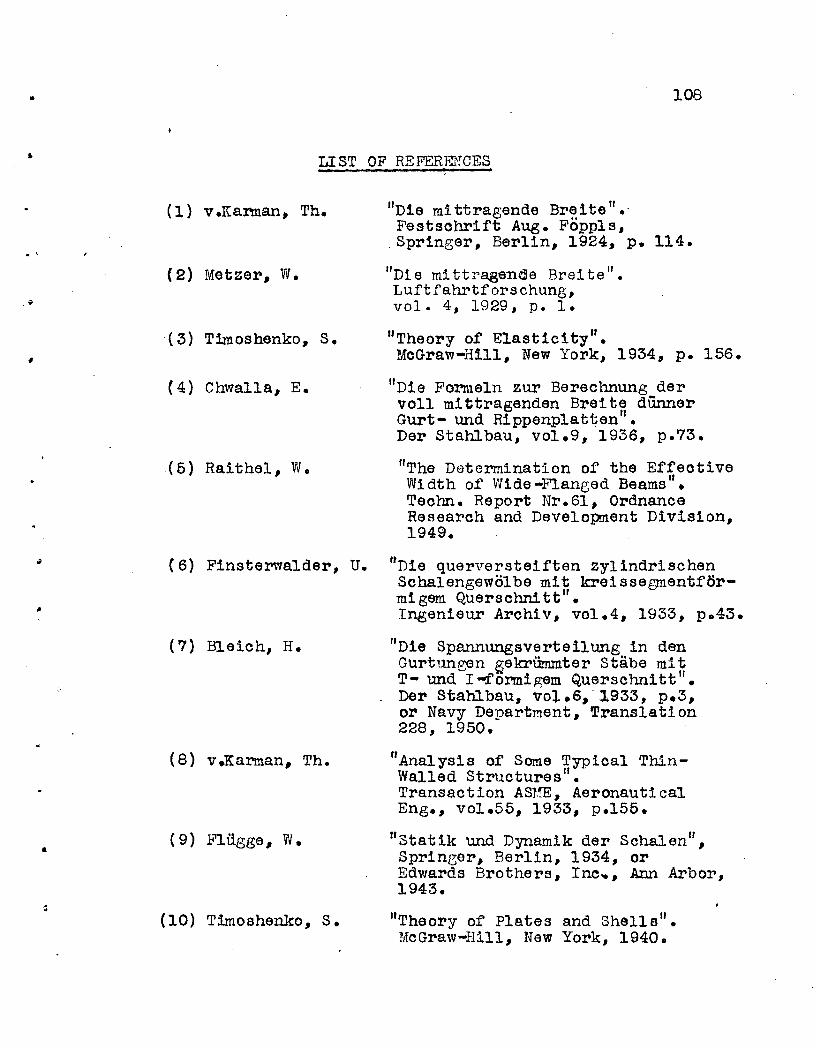
• 108
LIST OF REFERENCES
. ,
(1) v.Karman, Th.
(2) Metzer, W.
.( 3) Timoshenko, S.
(4) Chwalla, E.
(5 ) Raithel, W.
IID1e mittragende Br~itefl•.Festsohrift Aug. Foppls,Springer, Berlin, 1924, p. 114 •
"Di e mi ttragende Brei te II •
Luftfahrtforschung,vol. 4, 1929, p. 1.
"Theory of Elasticity" •MoGraw-Hill, New York, 1934, p. 156.
"Die Formeln zur Berechnung dervoll mittragenden Breite dUnnerGurt- und Rippenplatten".Der Stahlbau, vol.9, 1936, p.73.
liThe Determination of the EffeotiveWi dth of' Wide -Flanged Beams".Teohn. Report Nr.61, OrdnanceResearch and Development Division,1949.
(7) Bleich, H.
"
(6) Finsterwalder, U. "Die querversteiften zylindrischenSchalengewolbe mit kreissegmentformlgem Querschnitt ll
•
Ingenieur Archlv, vol.4, 1933, po43.
"Die Spannungsverteilung in denGurtungen ~ekriimmter Stabe mitT- und I-.f'ormigem Querschnitt".Dar Stahlbau, vol.6,-1933, p.3,or Navy Department, Translation228, 1950.
•
(8) veKarman, Th.
(9) l?liigge, W•
(10) Timoshenko, S.
"Analysis of Some Typical ThinWalled Structures II.
Transaction AS1!E, Aeronauti calEng., vol.55, 1933, p.155.
"Statik und Dynamik der Schalen ll,
Springer, Berlin, 1934, orEdwards Brothers, Ino.. , Ann Arbor,1943.
"Theory of Plates and Shells".McGraw-Hill, New York, 1940.
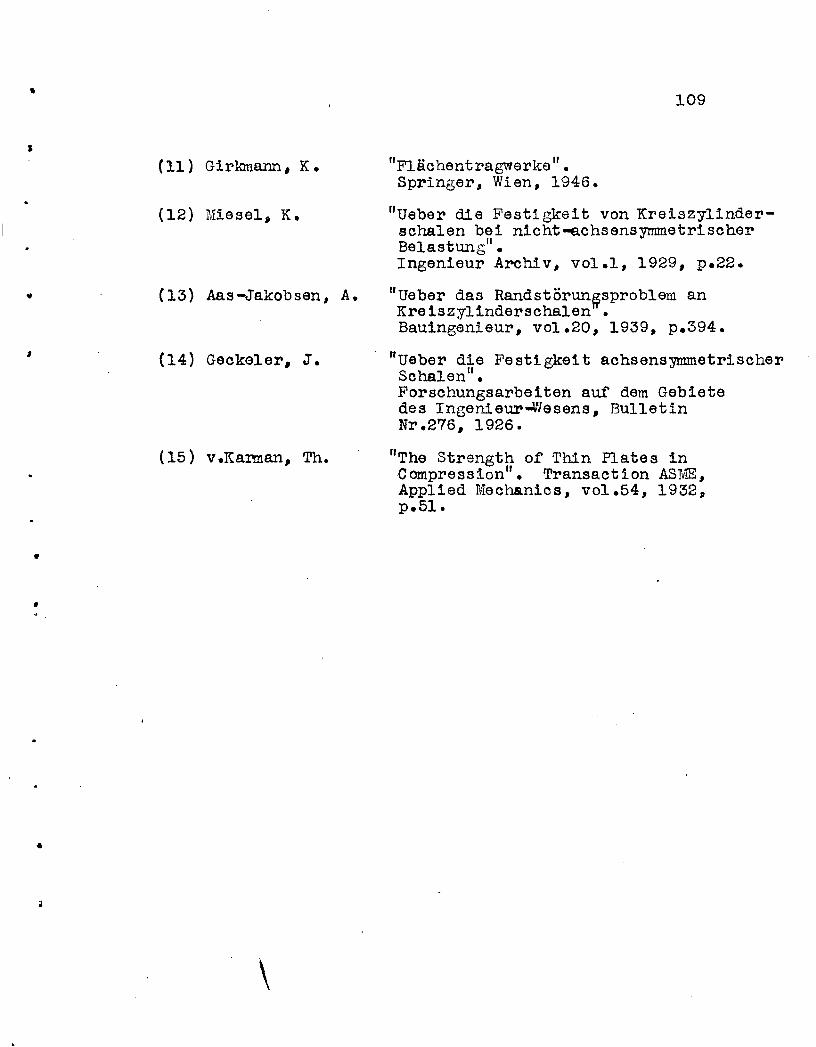
•
J
"
I
•
•
•
(11) Girkmann, K.
(12) Miesel, K.
(13) Aas-Jakobsen, A.
(14) Gecke1er, J.
(15) v.Karman, Th.
\
109
"Flachentragwerke fl •Springer, Wien, 1946.
flUeber die Festlgkeit von Kreiszylinderschalen bei n1cht-achsensymmetrischerBelastung" •Ingenieur Archiv, vol.l, 1929, p.22.
flUeber das Randstorun~sproblemanKre1szy11nderschalen •Baulngenieur, vol.20, 1939, p.394.
"ueber die Festigke1t achsensymmetrischerSchalen ll
•
Forschungsarbelten auf dem Gebletedes InBenieur~~esens, BUlletinNr.276, 1926.
IfThe Strength o~ Thin Plates inCompression". Transaction ASME,App11ed Mechanics, vol.54, 1932,p.51 •

•
t
•
I
•
•
110
V I T A
The author was born as the fifth child of Josef
and Alice ThUrlimann on February 6, 1923 in Gossau,
st.~ Gallen, Switzerland•
Despite an old family tradition in the medical
profession he chose a technical career and entered theII
Swiss Federal Institute of Technology, Zurich, Switzer-
land in September 1942. He graduated in December 1946
with a diplClna in civil engineering.
During 1947 and 1948 he worked as a research
"assistant at the "Institut fur Baustatlk" at the Swiss
Federal Institute of Technology under Professor P. Lardy •
In October 1948 he came to Lehigh University,
Bethlehem, Pao and in February 1949 was put in charge·
of a two year research project on Shell Arch Roof.
Constructions at Fritz Engineer~ngLaboratory, Lehigh
University.
. \


