
www.knaufinsulation.co.uk
Housing
Design Partner Series December 2004CI/SfB 81 (21.3) Rr2

HOUSING
2
Introduction and services 2 - 3
Single residence system application selection 4 - 5
Multiple residence system application selection 6 - 7
Design considerations
Thermal 8 - 9
Fire 10 - 13
Acoustic 14 - 15
Ventilation and condensation 16
Specification tips 17
Design solutions
Metal and timber 18 - 21
Masonry 22 - 25
Best practice detailing 26 - 29
Project profiles 30 - 31
Knauf Drywall systems – delivering solutions to meet customer needs
Knauf is a family owned
company with approximately
18,000 employees worldwide.
Founded originally in Germany
in 1932, Knauf entered the
UK market in 1988 and was
rebranded Knauf Drywall in 2003.
With two major manufacturing
sites in the UK, Knauf Drywall
is one of the leading suppliers
of gypsum based materials in
the UK. The UK manufacturing
facilities are set up to adapt
quickly to changing requirements
and to offer maximum flexibility to
suit specific needs. All production
has the assurance of quality to
BS EN ISO 9001: 2000.

3
Housing expertiseFrom initial concepts of housing specifications, where our Housing Managers are on hand to guide and assist, to our technical helpline,you are always guaranteed a rapidresponse to help solve any problemsyou may have.
This guide offers advice on the various design considerations specificto housing and offers a number of proposals for drywall design solutions. It is, however, merely a taste of thewhole service which Knauf Drywallcan offer.*
Service
At Knauf Drywall we understand and deliver the high level of servicethat our customers need and expect.Our flexible approach means that we do whatever we can to help, working within the framework of our customer’s business.
Whatever the size or nature of theproject, a professional member of the Knauf Drywall Team can alwayshelp.
Technical excellence
We are committed to continually providing superior, innovative technical solutions, not only with ourproducts but with revolutionary supporttools for our customers.
Quality
We take pride in the products andservice we provide and recognise that the measure of quality will alwaysbe judged through the eyes of our customers. To this end, Knauf Drywallis committed to continually improvingnot only its products but also the performance of the business.
* The Knauf Drywall manual gives more information and can be accessed on line at:
www.knaufdrywall.co.uk/themanual
Customer Service 0800 521 050 Customer Service email [email protected] Technical Service 01795 416259 Website www.knaufdrywall.co.uk
INTRODUCTION AND SERVICES

HOUSING
4
Internal floors
Metal and timber page 19
Internal floor junctions
With separating wall page 26
Service pipepenetrations page 27
SINGLE RESIDENCE
Knauf Drywall recognises that each part
of a new dwelling holds unique challenges.
To help you navigate this guide, the individual
construction elements of a single dwelling and
the appropriate page references for information
relevant to them are detailed opposite.
SYSTEM APPLICATION SELECTION SINGLE RESIDENCE

5
Internal walls
Metal and timber page 18
Separating walls
Metal and timber page 19
Masonry page 22
Door jambs
Best practice page 28
Separating floors
Metal and timber page 20
Masonry page 23
Lofts
Warm roof solution page 21
Cold roof solution page 21
Medium to heavyweight fixings
Best practice page 29
Switch boxes and sockets
Best practice page 27
Open spaces
Masonry page 25
Partition interface withsuspended ceiling page 26
External walls
Metal and timber page 21
Masonry page 24
Flanking detail page 27

HOUSING
6
Internal walls
Metal and timber page 18
Firstfloor
Groundfloor
MULTIPLE RESIDENCE
Medium to heavyweight fixings
Best practice page 29
Multiple dwellings present different challenges to
those of single dwellings, such as increased separating
wall and floor requirements. Detailed here are the
construction elements of a typical multiple dwelling and
the appropriate page references for relevant information.
SYSTEM APPLICATION SELECTION MULTIPLE RESIDENCE
Communal areas:
Entrance lobbies, stairwells and landings, hallways and corridors

7
Switch boxes and sockets
Best practice page 27
Separating floors
Metal and timber page 20
Masonry page 23
Open spaces
Partition interface withsuspended ceiling page 26
Stairwells and stairenclosures page 25
Separating walls
Metal and timber page 19
Masonry page 22
Door jambs
Best practice page 28
Internal floors
Metal and timber page 19
Internal floor junction
With separating wall page 26
Service pipepenetrations page 27
External walls
Metal and timber page 21
Masonry page 24
Flanking page 27

HOUSING
0.25
0.2
0.16
0.25
0.250.25c
0.35c
0.35 0.35
Loft
Unheated space
Areas in whichKnauf Drywall systemscan be used
8
Fig. 1: Diagrammatic summary of Elemental Method
Areas in which Knauf Drywall systems can be used
a if windows have wood or PVC frames
b if windows have metal frames
c includes the effect of the unheated space
Objectives of regulationsi) Reduce emissions of green house
gases emitted from dwellings by 12.5% in 2010 compared with emissions in 1990.
ii) Also to reduce C02 emissions by 20% in 2010 compared with emissions in 1990.
iii) Both the above are to be achieved by increased insulation efficiency along with enhancing construction practices to increase airtightness, heating and lighting efficiency.
The three calculation methodsMethod 1 – Elemental
This method can be used for alterations, extensions and new-buildwork. Calculations are made for aselection of building elements whichmust comply with the U-value thermalperformances shown in Table 1, opposite.
The Elemental method can be used
with a heating system deemed to
be efficient, for instance, gas or oil
boiler heat pump, community heating
with CHP or biogas or biomass fuel.
Boiler efficiency is demonstrated by
achieving gas SEDBUK values not less
than those in Table 2. It can not be
used for electric heating or other
heating systems.
Method 2 – Target U-value
Here, an average U-value requirement
is established for the building. This
U-value is derived from the equation
set out in the Building Regulations.
There is a degree of latitude as to how
this U-value is then met, which gives
the designer some flexibility. This
calculation method also takes into
consideration solar gain, efficiency of
heating system (any system can be
Relevant documentBuilding Regulations Approved Document LI ‘Conservation of fuel andpower in dwellings’ for England andWales and Part J for Scotland (April2002).
The following pages set out some of the construction and design issues that must be addressed when using Knauf Drywall products and systems for new and refurbishment housebuilding projects.
We have referred extensively to the appropriate Building Regulations, but due to limitations of space, have condensed their content to try to show information relevant to the specifiers and designers using this document.
In practice, the Building Regulations should be referred to as definitive guidance.
DESIGN CONSIDERATIONS
THERMAL CONSIDERATIONS
DESIGN CONSIDERATIONS
Average U-value = 2.0a or 2.2b

9
Table 1 – Elemental Method: U-values (W/m 2K) for construction elements
Exposed element U-value U-value for Scotland only requirement (using other heating systems)
Pitched roof with insulation between rafters1,2 0.2 0.18
Pitched roof with insulation between joists 0.16 0.16
Pitched roof with integral insulation 0.25 N/A
Flat roof3 0.25 0.22
Walls, including ground floors 0.35 0.27
and basement floors (0.30 – Scotland)
used), and the performance of glazed
areas and doors.
Method 3 – Carbon index
This method requires that the carbonindex (defined in the SAP – theGovernment Standard Assessment Procedure) for the dwelling(s) is notless than 8.0.
Assessment of compliance is by thecalculation of the total energy use ofthe building. This, in turn, is derivedfrom the U-values of construction elements, the type and efficiency ofheating systems, ventilation etc.
Poorest U-valuesFor Methods 2 and 3, some elementsmay have a lower U-value than thoseshown in Table 1, provided that performance is compensated for in other areas and that risk of condensation is avoided. Table 3below shows the permissible minimawhen using Methods 2 and 3.
Table 2 – Minimum boiler SEDBUK to enable adoption of the U-values in Table 1, and reference boiler SEDBUK for use in the Target U-value Method.
Central heating system fuel SEDBUK (%)4
Mains natural gas 78
LPG 80
Oil 5 85
Notes to Tables 1, 2 and 3:
1 Any part of a roof having a pitch of 70° or more can be considered as a wall.
2 For the sloping parts of a room-in-the-roof constructed as a material alteration, a U-value of 0.3 W/m2K would be reasonable.
3 Roof of pitch not exceeding 10°
4 For boilers for which the SEDBUK is not available, the appropriate seasonal efficiency value from Table 4b of the SAP may be used instead (see paragraphs 0.17 - 0.18).
5 For oil-fired combination boilers, a SEDBUK of 82%, as calculated by the SAP-98 method, would be acceptable.
6 Whilst parts of these elements may (within the limits given in Table 3) have poorer U-values than those given in Table 1, it will not normally be practical to make sufficient allowances elsewhere in the design for the whole element to be built to these standards.
Table 3 – Poorest U-values (W/m 2K) for parts of elements acceptable as a general rule when using the Target U-value and Carbon Index Methods.
Element Poorest acceptable U-value
Parts of roof 6 0.35
Part of exposed wall or floor 0.7
Customer Service 0800 521 050 Customer Service email [email protected] Technical Service 01795 416259 Website www.knaufdrywall.co.uk

HOUSING
10
Note to Table 4:
National classifications do not automaticallyequate with the equivalent classifications in the European column, therefore products cannot typically assume a European class,unless they have been tested accordingly.
i) Due to multiple occupancy, a high degree of compartmentation is required to reduce the probability of fire spreading beyond the dwelling in which it originates.
ii) Where fires start in communal areas, the construction should be such that it minimises the spread of the fire.
Flats and Maisonettes above 4.5 m
As with houses over 4.5 m, the thrustof the Building Regulations is that additional escape routes be providedin the form of protected hallways oralternative exits. There is a further stipulation that any door to a habitable room is not more than 9 mfrom the entrance door.
Part B2 – Internal fire spread (linings)
Building Regulation requirements are:
To inhibit the spread of fire within thebuilding, the internal linings shall:
a) Adequately resist the spread of flame over their surfaces.
b) Have, if ignited, either a rate of heat release or a rate of fire growth, which is reasonable in the circumstances.
The above can be achieved by selection of materials, such as Knaufplasterboard, that have low rates ofsurface spread of flame. It is also beneficial for material to have a lowrate of heat release, minimising thematerial’s contribution to fire growth.
These qualities are particularly important in circulation or communalspaces, where it will often be liningsthat must minimise the spread of flameto give the occupants more escapetime.
Table 4 – Classification of linings in residential situations
Location National class European class
Small rooms of area not more than:
4 m 2 in residential accommodation;
Domestic garages of area not more than 40 m 2 3 D-s3, d2
Other rooms (including garages)
Circulation spaces within dwellings 1 C-s3, d2
Other circulation spaces,including the
common areas of flats and maisonettes 0 B-s3, d2
DESIGN CONSIDERATIONS
FIRE CONSIDERATIONS B4 – To restrict spread of fire from onestructure to the next by constructingexternal walls and roofs that effectivelyinhibit firespread.
Complying with the regulationsPart B1, Section 2 – dwellinghouses Houses below 4.5 mFor one or two storey houses, with a floor below 4.5 m above groundlevel, the Building Regulations demandthat, in the event of a fire, early warning is provided and that suitableescape routes are available from eachstorey, but that these elements do not interfere with the day-to-day convenience of the occupants.
Generally speaking, points of risk such as cooking facilities and meansof escape such as stairways or corridors are identified as requiringspecial consideration as far as fire-resisting construction is concerned.
Houses above 4.5 mIn houses with a floor or multiple floors above 4.5 m, it is necessary to provide additional escape routes(generally protected stairways unlessover the roof) and exits.
Flats and Maisonettes below 4.5 mProvisions are generally as for housesexcept that:
Relevant documentBuilding Regulations Approved Document B, 2000 (amended 2002)edition. The parts relevant to this sector brochure are:
• B1: Means of warning and escape.
• B2: Internal fire spread (linings).
• B3: Internal fire spread (structure).
• B4: External fire spread.
Building Regulation requirements are:
B1 – To ensure the correct design, construction and provision of means of escape for persons in the event of a fire.
B2 – To ensure, through appropriateconstruction and workmanship, thatfirespread over the internal linings of buildings is inhibited.
B3 – To ensure the stability of buildings in the event of fire by creating separated compartments within buildings to inhibit internalspread of fire. To create sufficient and effective separation betweenadjoining buildings.
To inhibit unseen spread of smoke and fire via concealed spaces withinbuildings.
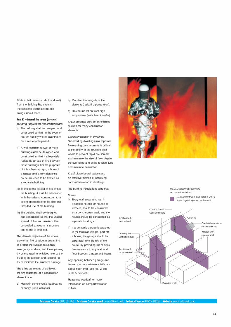
Fig.2: Diagrammatic summary of compartmentation
Compartment walls and floors in which Knauf Drywall systems can be used.
11
Table 4, left, extracted (but modified)from the Building Regulations, indicates the classifications that linings should meet.
Part B3 – Internal fire spread (structure)
Building Regulation requirements are:i) The building shall be designed and
constructed so that, in the event of fire, its stability will be maintained for a reasonable period.
ii) A wall common to two or more buildings shall be designed and constructed so that it adequately resists the spread of fire between those buildings. For the purposes of this sub-paragraph, a house in a terrace and a semi-detached house are each to be treated as a separate building.
iii) To inhibit the spread of fire within the building, it shall be sub-divided with fire-resisting construction to an extent appropriate to the size and intended use of the building.
iv) The building shall be designed and constructed so that the unseen spread of fire and smoke within concealed spaces in its structure and fabric is inhibited.
The ultimate objective of the above, as with all fire considerations is, first to protect the lives of occupants, emergency workers, and those passingby or engaged in activities near to thebuilding in question and, second, totry to minimise the structural damage.
The principal means of achieving the fire resistance of a construction element is to:
a) Maintain the element’s loadbearingcapacity (resist collapse).
b) Maintain the integrity of the elements (resist fire penetration).
c) Provide insulation from high temperature (resist heat transfer).
Knauf products provide an efficientsolution for many construction elements.
Compartmentation in dwellings
Sub-dividing dwellings into separatefire-resisting compartments is critical to the ability of the structure as awhole to prevent rapid fire spread and minimise the size of fires. Again,the overriding aim being to save livesand minimise destruction.
Knauf plasterboard systems are an effective method of achieving compartmentation in dwellings.
The Building Regulations state that:
Houses
i) Every wall separating semi-detached houses, or houses in terraces, should be constructed as a compartment wall, and the houses should be considered as separate buildings.
ii) If a domestic garage is attached to (or forms an integral part of) a house, the garage should be separated from the rest of the house, by providing 30 minutes fire resistance to any wall and floor between garage and house.
Any opening between garage andhouse must be a minimum 100 mmabove floor level. See Fig. 2 andTable 5 overleaf.
Please see overleaf for more information on compartmentation in flats.
Protected shaft
Junction with protected shaft
Opening i.e.ventilation duct
OpeningJunction with external wall
Junction with external wall
Combustible materialcarried over top
Construction of walls and floors
Customer Service 0800 521 050 Customer Service email [email protected] Technical Service 01795 416259 Website www.knaufdrywall.co.uk

HOUSING
12
FlatsIn buildings containing flats ormaisonettes, the following should beconstructed as compartment walls orcompartment floors:
i) Every floor (unless within a maisonette, i.e. between one storey and another within one dwelling); and
ii) Every wall separating a flat or maisonette from any other part of the building*; and
iii) Every wall enclosing a refuse storage chamber.
* ‘any other part of the building’ does not
include an external balcony/deck access.
Other residential buildingsAll floors should be constructed ascompartment floors.
Loft conversions
In a dwelling where only one storey isbeing added, there are no more than2 habitable rooms and the total area
Roof space
Stairway
Fire-resistingenclosure to stairway
Fire-resisting ceiling
is not more than 50 m 2, the existingfirst floor construction must have atleast a modified 30 minutes fire resistance where the floor separatesonly rooms (not circulation spaces).
In other circumstances, the full 30minute standard is required. See Table 5 opposite.
Other considerationsConcealed spaces (cavities)
Concealed spaces or cavities in theconstruction of a building provide a ready route for smoke and flamespread. This is particularly so in thecase of voids above other spaces in a building, e.g. above a suspendedceiling or in a roof space. As anyspread is concealed, it presents agreater weakness in the fabric of the building. Provisions are made to restrict this by interrupting cavitieswhich could form a pathway around a barrier to fire, sub-dividing extensivecavities, and by closing the edges of openings.
Protected shafts
Any stairway or other shaft passingdirectly from one compartment toanother should be enclosed in a protected shaft so as to delay or prevent the spread of fire betweencompartments.
Knauf Drywall offers a comprehensive range of shaftwall solutions. For further information,please refer to the ‘Manual’.
External walls
The requirement is for sufficient fire-resistance to prevent fire spreadacross the relevant boundary. If anexternal wall is more than 1 metrefrom the relevant boundary, the wallonly needs fire resistance from theinside.
Fig. 4: Arrangements of compartmentation in a house over 4.5 m high
Areas where Knauf Drywall systems can be used
Fig. 3: Buildings over 30 m in heightIn a building over 30 m in height, all storeysshould be separated by compartment floors.
Areas where Knauf Drywall systems can be used
Roof space
Stairway
Fire-resistingenclosure to stairway
Cavity barrier(s)in roof space
With cavity barriers With fire-resisting ceiling
DESIGN CONSIDERATIONS
FIRE CONSIDERATIONS

13
Notes to Table 5:
1 This table covers the most commonrequirements affecting housing. For acomprehensive listing, reference shouldbe made to the Building Regulations.
2 BS 476: Part 21 for loadbearing elements, Part 22 for non-loadbearing elements, Part 23 for fire-protecting suspended ceilings. BS 476: Part 8 results are acceptable for items tested or assessed before 1st January 1998.
3 Applies to loadbearing elements only (see B3.ii and Appendix on the Building Regulations).
4 Guidance on increasing the fire resistance of existing timber floors is given in BRE Digest 208 ‘Increasing the fire resistance of existing timber floors’ (BRE 1998).
5 A suspended ceiling should only be relied on to contribute to the fire resistance of the floor if the ceiling meets the appropriate provisions given in Table A3 of the Building Regulations.
6 The guidance in Section 14 of the Building Regulations allows such walls to contain areas which need not be fire-resisting (unprotected areas).
7 Unless needed as part of a wall in ‘External Walls’ a or b.
Modifications referred to in Table 6:
8 The floor over a basement (or if there is more than 1 basement, the floor over the topmost basement) should meet the provisions for the ground and upper storeys if that period is higher.
9 Increased to a minimum of 60 minutes for compartment walls separating buildings.
10 Reduced to 30 minutes for any floor within a maisonette, but not if the floor contributes to the support of the building.
11 Refer to paragraph 8.11 of the Building Regulations regarding the acceptability of 30 minutes in flat conversions.
12 30 minutes in the case of 3 storey dwelling-houses, increased to 60 minutes minimum for compartment walls separating buildings.
13 Refer to paragraph 8.10 (page 63 of the Building Regulations) regarding the acceptability of 30 minutes in flat conversions.
Table 5 – Fire resistance required for elements of structure 1
Minimum provision when tested to the relevant parts of BS 476 2 / EN 1363
Part of building Loadbearing Integrity Insulation Method of exposure
capacity 3 minutes minutes
Loadbearing wall (which
is not a compartment wall) see table 6 N/A N/A Each side separately
Floors 4
a) in upper storey of two-storey
dwelling house (but not over a garage
or a basement) 30 15 15 From the underside 5
b) any other floor including
compartment floors see table 6 see table 6 see table 6
External walls
a) any part less than 1m from any
point on the relevant boundary. see table 6 see table 6 see table 6 Each side separately
b) any part 1m or more from
relevant boundary 6 see table 6 see table 6 15 From inside of the building
c) any part adjacent to
an external escape route 30 30 No provision 7 From inside of the building
Compartment walls 60, or 60, or 60, or
(separating occupancies) see table 6 see table 6 see table 6 Each side separately
Compartment walls
(not separating occupancies) see table 6 see table 6 see table 6 Each side separately
Garage wall
(separating an attached garage side or
integral garage from a dwelling house) 30 30 30 From the garage side
Fire-resisting construction
(in dwellings not described elsewhere) 30 30 30 Each side separately
Table 6 – Minimum periods of fire resistance
Purpose group of building Minimum periods (minutes) for elements of structure in a:
Basement storey 8 including floor Ground or upper storey height (m)over depth (m) of a lowest basement of top floor above ground in a building
or separated part of a building
more not more not more not more not more more than than 10 than 10 than 5 than 5 than 18 than 30
1) Residential (domestic):
a) Flats and maisonettes 90 60 30 9 60 10,11 90 10 120 1 0
b) and c) dwellinghouses N/A 30 9 30 9 60 12 N/A N/A
2) Other residential 90 60 30 9 60 90 120 13

HOUSING
14
Relevant documentBuilding Regulations ApprovedDocument E “Resistance to the passageof sound”. The parts relevant to this sector brochure are:
• E1: Protection of sound from other parts of the building and adjoining buildings.
• E2: Protection against sound within a dwelling house.
• E3: Reverberation in the common internal parts of buildings containing flats or rooms for residential purposes.
ObjectivesTo improve modern living standards by the provision of resistance to soundfrom other buildings, parts of the same building and the reduction ofreverberation from common parts ofbuildings.
The above is to be achieved by arange of enhanced requirements for theconstruction of walls, floors and ceilingsfor new build and material change ofuse projects.
Pre-Completion TestingPart E puts the onus on the builder to demonstrate that the stated
acoustic rating has been achieved by demanding that 10% of all newdwellings should be Pre-CompletionTested on-site.
Testing applies to separating walls and floors between dwellings. Both new build dwellings and thosenew dwellings created by what Part Edescribes as “Material Change of Use”, are covered. Material change of use relates to what would be morecommonly known as refurbishment and conversion work.
Testing must be carried out by a testbody with appropriate third partyaccreditation.
In new build situations, the use ofRobust Details (see below) obviates therequirements for mandatory Pre-Completion Testing.Pre-Completion Testing is not requiredfor internal partitions and floors.
Robust DetailsTo avoid the need for Pre-CompletionTesting, the industry, and in particularhousebuilders, led by the HBF, havewon approval of a series of performance-tested solutions which are
deemed to satisfy Part E. In relationonly to separating walls and floors,these solutions are site-tested systems –proven to achieve required performance levels – and are known asRobust Details. Sites taking advantageof these solutions must be registeredwith Robust Details Ltd.
There are also suggested constructionswithin Part E itself for separating elements. However, these systems arestill subject to Pre-Completion Testing.Several of these systems specify the useof 10kg plasterboard which KnaufDrywall can supply from our range of boards.
Where practical, Knauf Drywall recommends the use of Robust Details to avoid mandatory Pre-CompletionTesting in new-build situations.
Dealing with reverberation in ‘common parts’ of residential buildingsPart E3 of the Building Regulations concerns the reduction of reverberationand applies only to corridors, staircases, hallways and entrance halls giving access to flats or rooms forresidential purposes. Reverberation is
ACOUSTIC CONSIDERATIONS
Part E summary of requirements:Table 7 – Dwelling Houses & Flats: separating walls, floors and stairs
Airborne Sound Insulation Impact SoundDnT, w + Ctr dB L’nT, w dB (minimum values) (maximum values)
New build
Walls 45 –
Floors and stairs 45 62
Material change of use
Walls 43 –
Floors and stairs 43 64
Table 8 – Laboratory Values for new internal walls and floors
Airborne Sound Insulation Rw dB (minimum values)
New Build
Walls 40
Floors 40
Material change of use
Walls 40
Floors 40
Technical Data
dB (decibel)indicates the level of sound reduction required.
RwLaboratory measurement of airborne soundtransmission
DnT, w + CtrSite measurement of airborne sound with lowfrequency correction applied. The higher thefigure, the better the performance.
L’nT, wSite measurement of impact sound level. The lower the figure, the better the performance.
DESIGN CONSIDERATIONS

15
Table 9 – Absorption coefficient data for common materials in buildings (as set out in the Building Regulations)
Material Sound absorption coefficient (α),in octave frequency bands (Hz)
250 Hz 500 Hz 1000 Hz 2000 Hz 4000 Hz
Suspended plaster or
plasterboard ceiling (with large
airspace behind) 0.15 α 0.10 α 0.05 α 0.05 α 0.05 α
Separating wall
Adjoining dwelling
Residential room
Residentialroom whereE1 applies
Residentialroom
Other room
Separating floor
defined as the persistence of sound in a space after the source of the soundhas stopped.
The ‘common’ parts of residential structures are deemed to require additional levels of sound absorption.
There are two methods of achieving the requirements:
Method ACover a specified area with an absorptive material of an appropriateclass, rated according to BS EN ISO11654: 1997 ‘Acoustics – soundabsorbers for use in buildings – rating of sound absorption’.
For entrance halls, corridors or hallwaysCover an area equal to or greater thanthe floor area with a class C absorptivematerial. Usually, this area will be theceiling.
For stairwells and stair enclosuresCalculate the combined area of: stairtreads, upper surfaces of intermediatelandings, upper surfaces of landings(not ground floor) and ceiling area oftop floor.
There are then two options:
i) use a class D absorptive material to cover an area at least equal to the calculated area.
ii) use a class C absorptive material, or better, to cover at least 50% of the calculated area.
In either case, ensure even distributionof the absorptive material – normally theunderside of intermediate landings,otherlandings and the ceiling of the top floor.
Proprietary acoustic ceilings, such asKnauf Apertura, will generally satisfyMethod A, but other absorptive materialcan be applied to any surface that facesinto the space.
Method BThis method takes into account the existing absorption provided by all surfaces, and can provide more designflexibility, or require less additionalabsorption than method A.
Its requirements are:
For entrance halls provide a minimum of 0.20 m2 totalabsorption area per cubic metre of the volume, distributed over availablesurfaces.
For corridors or hallways as above but a minimum of 0.25 m2.
The Building Regulations provide a formula for the calculation of the totalabsorption area (AT) (for full details seesection 7 of Part E, page 65), and aresatisfied when the appropriate amountof absorption area is provided for eachoctave range between 250 Hz and4000 Hz inclusively.
Table 9, below, contains typical absorption coefficient material data for plaster and plasterboard.
For other materials, measurements of absorption coefficient data should bedetermined using BS EN 20354: 1993and according to BS EN 11654:1997.
DefinitionsNew build
Any new, purpose-built construction project. Extensions, as new constructions, fall into this category.
Material change of use Defined as “where there is a change inthe purpose for which or circumstancesin which a building is used”. This couldbe an office converted to a residence,
Fig. 5: Insulation requirements for E1 (Table 7), separating elements
Airborne sound insulation
Impact and airborne sound insulation
Fig. 6: Insulation requirements for E2 (Table 8), internal elements
Airborne sound insulation
a shop altered to contain a flat, ahouse converted to flats etc.
ExceptionsDwellings sold before fitting outPart E specifies that measurement of sound insulation should be madebetween the available spaces and that steps should be taken to ensure that fitting out will not adversely affectthe sound insulation. Appropriate stepsare not defined in Part E.
Historic buildingsPart E leaves it to Building ControlOfficers to ensure that “everything reasonable has been done”,althoughthis is not defined in Part E. A noticemust be displayed within the building to show the sound insulation levelsachieved by testing.
Loft conversions No guidance is given in Part E.
Residentialroom
Bedroom or W.C.
Internal wall
Internalfloor
Residentialroom
Residentialroom
Customer Service 0800 521 050 Customer Service email [email protected] Technical Service 01795 416259 Website www.knaufdrywall.co.uk

HOUSING
16
DESIGN CONSIDERATIONS
Summary‘Cold’ duo-pitched roof (Fig. 7)
On each side of the roof a free airspace equivalent to a continuous 10 mm opening is required at theeaves or at low level.
‘Warm’ duo-pitched roof (Fig. 8)
On each side of the roof a free airspace equivalent to a continuous 25 mm opening is required at theeaves or at low.
A free airspace equivalent to a continuous 5 mm opening should alsobe provided at the ridge or at highlevel on each slope.
A minimum 50 mm clear air path mustalways be maintained between theinsulation and the underlay to ensureeffective through-ventilation.
VENTILATION & CONDENSATION CONSIDERATIONSThe regulations require that the roof
space should have eaves ventilation
running the full length of the eaves
promoting cross-ventilation eaves
to eaves equivalent to a continuous
10 mm opening.
Roofs with a pitch of less than 15° and those
where the ceiling follows the pitch of the roof
Flat roofs and pitched roofs, where the
insulation follows the pitch of the roof
(often referred to as ‘warm roofs’),
require ventilation on two opposite
sides. The level of ventilation should
have an area at least equal to
continuous ventilation running the full
length of the eaves and 25 mm wide.
The void between the roof deck and
the insulation should have a free
airspace of at least 5 mm. Counter
battens may be used where joists run
at right angles to air flow direction.
Pitched roofs also require 5 mm
continuous ventilation at the ridge line.
Vapour checks can reduce the amount
of moisture condensing in the void, but
cannot be relied on as an alternative
to ventilation unless a complete barrier
to moisture can be guaranteed.
Relevant documentBuilding Regulations approved document 1991 (1995 Edition).
• F1: Means of ventilation.• F2: Condensation.
ObjectivesTo encourage construction that provides adequate means of ventilation in dwellings and, closelylinked with the above, to preventexcessive condensation in roofs androof voids above insulated ceilings.
Meeting the requirementsF1 requirements can be met by providing the appropriate levels of mechanical and background ventilation for the designated roomtypes – habitable rooms, kitchens,common spaces, bathrooms and sanitary accommodation – each having specific stipulations.
F2 is split into two types of construction:
Roofs with a pitch of 15°
or more (pitched roofs)
This category is generally classified asa ‘cold roof’ where there is insulationat ceiling level and an unheated, uninhabited loft space above it.
10 mm10 mm
Not more than 10 m span
15° - 35° pitch
25 mm 25 mm
5 mm each side
50 mm clearair path
Fig. 8: ‘Warm’ duo-pitched roof
Fig. 7: ‘Cold’ duo-pitched roof
17
Metal studs – speed, accuracy and economyThe specification of metal studs givesparticular advantages over timber:
• Reduced waste.• Increased speed and ease
of erection.• Higher accuracy, no movement
or twisting due to shrinkage.• Reduced customer care issues.
There is also a greatly reduced chance of use by other trades for non-associated tasks. In the case ofinternal partitions, the use of KnaufAcoustic C Stud can obviate the need for an insulation quilt. Alwaysensure that Knauf Drywall metal studsare used within Knauf Drywallpartition systems to ensure the validityof all performance ratings and thewarranty.
Paper tapeAlways specify the use of Knauf Joint Tape for jointing plasterboards inceiling applications. The use of papertape significantly reduces the chancesof cracking due to movement of thebackground.
Reducing wastageWastage of plasterboard on sites can be reduced by ensuring that thecorrect board length is chosen to suitthe storey heights. Often, over-lengthboards are specified which then haveto be cut-down, increasing workingtime and waste.
For further information on waste management, please refer to ourEnvironmental brochure, available from our Literature Hotline: 08700 631 700.
Resilient bar for ceilingsThe specification of Knauf Resilient
Bar on ceiling systems brings threeadvantages:
• Sound reduction is increased (in some cases, obviating the need for an insulation quilt).
• The bars can be spaced to remove the need for noggings on 12.5 mm board, regardless of joist centres.
• Instances of cracking/nail popping are much reduced as the system will be more tolerant of background movement.
Recessed lights and other penetrationsWhen specifying recessed lighting and other penetrations through wallsand ceilings, consider the effect on thesystem’s performance with regards tofire and acoustic ratings. Always ensurethe manufacturer of the penetrationhas taken these into account.
Ensuring effective adhesion for ‘dot and dab’When specifying a ‘dot and dab’ plasterboard solution to fair faced in-situ concrete, it is necessary to takeinto account the releasing agent used,as well as the low-key, low-suction surface. The concrete should beallowed to fully dry, and all traces ofreleasing agent removed with a milddetergent. Knauf Betokontact shouldbe used to provide a key, before thewall can be lined using a KnaufDrywall ‘dot and dab’ solution.
Achieving high finish levelsWhen deciding on which finish toapply to plasterboard, considerationshould be given to the level of flatnessthat is required so that it suits the interior design and lighting conditions.For example, natural light at a shallowangle tends to highlight surface level
differences, and features such as dadorails require a uniformly flat surface inorder to be correctly mounted.
On a taped and jointed finish, themaximum increase of the crown of the joint allowed in BS 8212:1988 is 3 mm when measured using a 450 mm straight edge. A smaller maximum increase can be specified,but will be more time-consuming toachieve. The use of Knauf TaperedEdge plasterboards is recommendedwhen taping and jointing. If a uniformly flat surface is required thena Knauf skim plaster finish should bespecified.
If specifying a taped and jointed plasterboard finish, Knauf WallboardPrimer should be applied prior to the final finish (paint or wallpaper).The use of Wallboard Primer equalises suction across the surface and reducesthe chance of the joints being seenthrough the finish. It also reduces moisture absorption and the risk of discolouration.
When checking the standard of jointing prior to completion, the use of lighting similar to that expected
SPECIFICATION TIPS
when occupied will provide the mostaccurate check, and subsequentlyreduce the possibility of customer careissues relating to the finished surface.
SequenceThe British Standard Code of Practicefor plasterboard partitions and dry linings (BS 8000: Part 8: 1994) recommends the following sequence of work:
Fix ceiling linings first, then partitions,followed by wall linings. Whenever itis practical to do so, apply wall liningsin sequence working away from doorsand windows and towards internalangles. As far as possible, locatepaper bound board edges at salientcorners.
Please note that where a parge coat is specified to a masonry separatingwall, then the parge coat should beapplied first, before the ceiling lining, and should cover all exposedmasonry.

HOUSING
18
DESIGN SOLUTIONS
When designing dwellings, there are various requirements
that must be met. Identifying the appropriate solutions can
sometimes be confusing. Recognising this, Knauf Drywall
has devised a simple, cost effective range of solutions.
Detailed in this section is a range of solutions that you
can specify with confidence.
DESIGN SOLUTIONS
KNAUF DRYWALL SOLUTIONS: METAL AND TIMBER(For Masonry solutions, see page 22)
Internal wallsThese are laboratory tested Knauf Drywall proprietary systems that meet the legal requirements for acoustic and fire performance as laid down in the BuildingRegulations. All systems have a maximum 3000 mm height.
Solution 2• 15 mm Knauf Wallboard
• 70 mm Knauf Acoustic C Stud at 600 mm centres
• 30 minutes fire resistance
• 40 dB Rw airborne sound
Solution 3• 12.5 mm Knauf Soundshield
• 63 mm timber stud at 600 mm centres
• 25 mm Crown Partition Roll
• 30 minutes fire resistance
• 40 dB Rw airborne sound
Solution 1• 12.5 mm Knauf Soundshield
• 50 mm Knauf Acoustic C Studat 600 mm centres.
• 30 minutes fire resistance
• 40 dB Rw airborne sound
70 mm Knauf Acoustic C Stud
15 mm KnaufWallboard 25 mm Crown
Partition Roll
12.5 mm KnaufSoundshield
63 x 35 mmTimber stud
50 mm KnaufAcoustic C Stud
12.5 mm KnaufSoundshield

19
Separating wallsThese systems all comply with Robust Details Ltd for Part E of the Building Regulations. Pre-CompletionTesting is still required for Robust Detail solutions unless the site is registered with Robust Details Ltd. Allsystems have a maximum 3000mm height.
70 mm Knauf C Stud
12.5 mm Knauf Soundshield 2 layers
200 mm min
50 mm Rocksil RS 33
19 mm Knauf Plank
Timber stud
60 mm Crown Wool
240 mm min
12.5 mm Knauf Soundshield
Notes to Separating walls:
2 For further information on the specification of Robust Details, refer to Knauf Drywall Technical Services.
3 Airborne sound on-site figures are the Building Regulation’s minimum requirements as tested on-site. Each of these solutions has the potential to significantly exceed this figure when correctly installed.
Solution 2 (E-WS-1)2
• 2 layers 12.5 mm Knauf Soundshield(outer layer mounted vertically, inner layer mounted horizontally) each side, all layer joints staggered.
• Twin frame, 70 mm Knauf C Studs at 600 mm centres, braced accordingly, in separate Knauf U-channels, spaced to give minimum 200 mm cavity width.
• 50 mm Rocksil RS33 insulation slabmounted between the rows of studs.
• 60 minutes fire resistance
• 45 DnT, w + Ctr dB airborne sound on-site 3
Solution 3 (E-WT-1)2
• 12.5 mm Knauf Soundshield (outer layer,mounted vertically) and 19 mm Knauf Plank (inner layer, mounted horizontally), all layer joints staggered.
• Twin frame, two rows of timber studs at max. 600 mm centres, spaced to give minimum 240 mm cavity width.
• 60 mm Crown Wool Insulation mounted between studs on each frame.
• 60 minutes fire resistance
• 45 DnT, w + Ctr dB airborne sound on-site 3
Solution 1 (E-WS-1)2
• 12.5 mm Knauf Soundshield (outer layer, mounted vertically) and 19 mm Knauf Plank (inner layer, mounted horizontally), all layer joints staggered.
• Twin frame, 70 mm Knauf C Studs at 600 mm centres, braced accordingly, in separate Knauf U-channels, spaced to give minimum 200 mm cavity width.
• 50 mm Rocksil RS33 insulation slabmounted between the rows of studs
• 60 minutes fire resistance
• 45 DnT, w + Ctr dB airborne sound on-site 3
70 mm Knauf C Stud
19 mm Knauf Plank
50 mm Rocksil RS 33
200 mm min
12.5 mm Knauf Soundshield
Internal floorsThese are laboratory tested Knauf Drywall proprietary systems that meet the legal requirements for acoustic and fire performance as laid down in the Building Regulations.
Solution 2• 15 mm Knauf Wallboard to underside of
timber joists.
• 30 minutes fire resistance
• 40 dB Rw airborne sound
Solution 3• 15 mm Knauf Wallboard to underside of
timber engineered I-joists.
• 30 minutes fire resistance
• 40 dB Rw airborne sound
Solution 1• 12.5 mm Knauf Soundshield to
underside of timber joists1.
• 30 minutes fire resistance
• 40 dB Rw airborne sound
18 mm tongue and groove flooring
Timber joist
12.5 mm KnaufSoundshield
Note to Internal floors:
1 600 mm centres may be used with noggings, or if 15 mm Knauf plasterboard is specified, without noggings.
Timber joist15 mm Knauf Wallboard
18 mm tongue and groove flooring
22 mm tongue and groove flooring
Timber engineered'I-joists'
15 mm KnaufWallboard

HOUSING
20
Separating floors
Solution 1 complies with Robust Details Ltd for Part E of the Building Regulations.Pre-Completion Testing is still required for Robust Detail solutions unless the site isregistered with Robust Details Ltd.
There is currently no proposed Government detailed Robust Standard Detail for Part E of the Building Regulations to suit the use of non-engineered timber ‘I-joists’ (ie. traditional timber joists). Solution 2 is a Knauf Drywall recommendedsolution which has been laboratory tested, but is subject to possible further Pre-Completion Testing, if specified.
Solution 1 (Robust Detail) (E-FT-1)4
Floating Floor Treatment:
• 18-22 mm flooring board on 19mm Knauf Plank, over resilient composite deep battens with 25 mm Crown Partition Roll between (not under).
• Resilient battens sized to give 70 mm minimum void when loaded.
over
Timber Floor:
• Minimum 15 mm sub-decking over minimum 240 mm engineered timber ‘I-joists’.
• 100 mm Crown Wool insulation between joists. Knauf Resilient Bars at 400 mm centres mounted perpendicular to joists.
• Upper layer 15 mm Knauf Soundshield and lower layer 15 mmKnauf Wallboard fixed to resilient bars.
• 60 minutes fire resistance
• 45 DnT, w + Ctr dB airborne sound on-site 5
• 62 L’nT, w dB impact sound on-site 5
Solution 2 (Knauf Drywall recommended solution)Timber Floor:
• 18-22 mm flooring glued to Knauf resilient isolation strip over the top surface of the joist.
• 19 mm Knauf plank mounted on Knauf Angles between the joists.
• 100 mm Crown Wool insulation between joists.
• Knauf Resilient Bars at 400 mm centres mounted perpendicular to joists.
• 2 Layers 15 mm Knauf Wallboard fixed to resilient bars.
• 60 minutes fire resistance
• 56 dB Rw airborne sound (lab test) 6
• 61 L’nT, w dB impact sound6
Floating floor treatment 15 mm sub decking19 mm Knauf Plank100 mm
Crown Wool
240 mm Engineered timber 'I-joists'
Knauf Resilient Bar15 mm KnaufSoundshield
15 mm KnaufWallboard
19 mm Knauf Plank Tongue and groove flooring
Timber joist
15 mm Knauf Wallboard(2 layers)
Knauf Resilient Bar
Knauf Angle
100 mm Crown Wool
Knauf resilient isolation strip
Notes to Separating floors:
4 For further information on the specificationof Robust Details, refer to Knauf Drywall Technical Services.
5 Airborne and impact sound on-site figures are the Building Regulations’ minimum requirements as tested on-site. This solution has the potential to significantly exceed this figure when correctly installed.
6 Airborne and impact sound figures for this system are laboratory tested. This system has the potential to exceed the Building Regulations’ minimum requirements when tested on-site.
DESIGN SOLUTIONS

Insulation to suit U = 0.16 W/m K2
12.5 mm Knauf Wallboard
(eaves ventilation required)
Insulation to suit U = 0.2 W/m K2
12.5 mm Knauf VapourshieldInternal floor (see page 19)
21
External walls
The inner plasterboard linings of loadbearing timber external walls play an important role in the fire performance of the wall, as well as providing both an effective vapour barrier (when Knauf Vapourshield is specifiedas the inner layer) and the decorative internal face.
SolutionInternal lining with plasterboard:
• Standard timber loadbearing construction with brick outer leaf, minimum 44 mm timber studs at maximum 600 mm centres, stud depth to suit insulation.
• Insulation between studs to suit U-value.
Inner lining:
• 2 layers of 12.5 mm Knauf plasterboard with staggered joints. Inner layer to be Knauf Vapourshield.
• 60 minutes fire resistance 7
• Airborne sound (dB Rw ) N/A 8
• 0.35 W/m 2K U-value (0.3 Scotland)
Notes to External walls:
7 Ground storey loadbearing wall, height of top floor above ground not more than 18 m.
8 Specific airborne sound performance may be required, subject to local planning requirements.
12.5 mm Knauf Wallboard
Min 44 mm wide loadbearing timber stud
100 mm brick outer leaf
12.5 mm Knauf Vapourshield
LoftsIn a warm roof situation, the required U-value (and any required fire or acoustic performance) applies to the pitched roof element itself, and does not include the loft floor. The loft floor itself is treated as an internal floor and should be specified as such (see page 19).
In a cold roof situation, the required U-value applies to the entire construction above the upper floor level.
Warm roof solutionNew build:
• Line internal surface of standard construction pitched roof with 1 layer 12.5 mm Knauf Vapourshield, fixed to rafters.Specify insulation to suit U-value.
• Fire resistance (minutes) N/A 9
• Airborne sound (dB Rw ) N/A 9
• 0.2 W/m 2K U-value(0.3 W/m 2K U-value if a conversion)
Cold roof solution• Standard roof construction with eaves ventilation and insulation
between joists: Line underside of timber joists with one layer of12.5 mm Knauf Wallboard. Specify insulation to suit U-value.
• Fire resistance (minutes) N/A 10
• Airborne sound (dB Rw) N/A 10
• 0.16 W/m 2K U-value
Notes to Lofts:
9 Specific fire resistance and airborne sound performances may be required, subject to local planning requirements (for example, in the vicinity of an airport flightpath).
10 There are no fire resistance or airborne sound performance requirements for the lining into the loft space. Specific fire resistance and airborne sound performances may be required for the entire roof construction, subject to local planning requirements (for example, in the vicinity of an airport flightpath).

HOUSINGHOUSING
22
KNAUF DRYWALL SOLUTIONS: MASONRY(For Metal and timber solutions, see page 18)
Separating wallsThese systems all comply with Robust Details Ltd for Part E of the BuildingRegulations. Pre-Completion Testing is still required for Robust Detail solutions unless the site is registered with Robust Details Ltd. All systems have a maximum 3000mm height.
Solution 1 (E-WM-2)1
• Cavity wall, block density 1350-1600 kg/m 3, each leaf thickness to be a minimum 100 mm,with minimum 75 mmcavity between leaves.
• Minimum 13 mm Knauf plaster finish applied to both room face sides
• 60 minutes fire resistance
• 45 DnT, w + Ctr dB airborne sound on-site 2
Solution 2 (E-WM-4)1
• Cavity wall, block density 1350-1600 kg/m 3, each leaf thickness to be a minimum 100 mm,with minimum 75 mmcavity between leaves.
• Nominal 8mm (minimum 6 mm) parge render coat, scratch finished, applied to both room face sides.
• 12.5 mm Knauf Wallboard dot and dabbed to both room face sides using Knauf Bonding Compound.
• 60 minutes fire resistance
• 45 DnT, w + Ctr dB airborne sound on-site 2
Solution 3 (E-WM-3)1
• Cavity wall, block density 1850-2300 kg/m 3, each leaf thickness to be a minimum 100 mm,with minimum 75 mmcavity between leaves.
• Nominal 8 mm (minimum 6 mm) parge render coat, scratch finished, applied to both room face sides.
• 12.5 mm Knauf Wallboard dot and dabbed to both room face sides using Knauf Bonding Compound.
• 60 minutes fire resistance
• 45 DnT, w + Ctr dB airborne sound on-site 2
Notes to Separating Walls:
1 For further information on the specification of Robust Details, refer to Knauf Drywall Technical Services.
2 Airborne sound on-site figures are the Building Regulations’ minimum requirements as tested on-site. Each of these solutions has the potential to significantly exceed this figure when correctly installed.
Block density 1350-1600 kg/m
Knauf plaster
Min. 75 mm
3
Min. 100 mm
12.5 mmKnauf Wallboard
Knauf BondingCompound dab
Parge coat
Block density 1350-1600 kg/m
Min. 75 mm
3
Min. 100 mm
12.5 mmKnauf Wallboard
Knauf BondingCompound dab
Parge coat
Min. 75 mm
Min. 100 mm
Block density 1850-2300 kg/m 3
DESIGN SOLUTIONS

23
Notes to Separating Floors:
3 For further information on the specification ofRobust Details, refer to Knauf Drywall Technical Services.
4 Airborne and impact sound on-site figures are the Building Regulations’ minimum requirements as tested on-site. Each of these solutions has the potential to significantly exceed this figure when correctly installed.
Floating floor treatment
15 mm Knauf WallboardKnauf Suspended Ceiling
65 mm sand and cement screed
150 mm precast concretefloor slab (300 kg/m )3
12.5 mm Knauf Wallboard
250 mm in-situ concretefloor slab (2400 kg/m )
Floating floor treatment
Knauf Suspended Ceiling
3
Separating floorsThese systems all comply with Robust Details Ltd for Part E of the BuildingRegulations. Pre-Completion Testing is still required for Robust Detail solutionsunless the site is registered with Robust Details Ltd.
Solution 1 (E-FC-1)3
Floating floor treatment:
• 18-22 mm flooring board over resilient composite deep battens sized to give 70 mm minimum void when loaded, or other treatment specified in RSD.
Masonry floor:
• 65 mm sand and cement screed or 40 mm proprietary screed (80 kg/m 2) directly bonded to minimum 150 mm precast concrete floor slab (min 300 kg/m 2).
Suspended ceiling:
• Knauf Suspended Ceiling system with minimum 75 mm void, one layer 15 mm Knauf Wallboard.
• 60 minutes fire resistance
• 45 DnT, w + Ctr dB airborne sound on-site 4
• 62 L’nT, w dB impact sound on-site 4
Solution 2 (E-FC-2)3
Floating floor treatment:
• 18-22 mm flooring board over resilient composite deep battens sized to give 70 mm minimum void when loaded, or other treatment specified in RSD.
Masonry floor:
• Minimum 250 mm in-situ concrete floor slab, minimum density 2400 kg/m 3.
Suspended ceiling:
• Knauf Suspended Ceiling system with minimum 75 mm void, one layer 12.5 mm Knauf Wallboard.
• 60 minutes fire resistance
• 45 DnT, w + Ctr dB airborne sound on-site 4
• 62 L’nT, w dB impact sound on-site 4

HOUSING
24
External wallsEither Knauf plasterboard on dabs, or Knauf plaster can be specified to provide the decorative internal finish to a masonry external wall. Unlike masonry separating walls, there is no requirement for the use of an additional parge coat if applying a plasterboard finish on dabs.
Solution 1Internal lining with plasterboard on dabs:
• Masonry cavity wall, brick outer leaf, aerated block inner leaf, with fully filled cavity5. Insulation and block specified to suit U-value and fire rating.
Inner lining:
• 1 layer of Knauf Wallboard adhered to blocks with Knauf Bonding Compound dabs.
• 60 minutes fire resistance 6
• Airborne sound (dB Rw ) N/A 7
• 0.35 W/m 2K U-value (0.3 Scotland)
Solution 2Internal plaster finish:
• Masonry cavity wall, brick outer leaf, aerated block inner leaf, with fully filled cavity5. Insulation and block specified to suit U-value and fire rating.
Inner lining:
• Minimum 13 mm thick Knauf MP75 plaster.
• 60 minutes fire resistance 6
• Airborne sound (dB Rw ) N/A 7
• 0.35 W/m 2K U-value (0.3 Scotland)
Notes to External walls:
5 The use of a fully filled cavity wall may not be permitted in areas of the country that are subject to high levels of wind-driven rain. Knauf Drywall manufactures a range of insulating laminate plasterboards that can be applied as the inner lining of the wall.
6 Ground storey loadbearing wall, height of top floor above ground not more than 18 m.
7 Specific airborne sound performance may be required, subject to local planning requirements.
DESIGN SOLUTIONS
Knauf Bondingcompound dab
Knauf Wallboard
Knauf plaster

25
Open spacesThe following advice is based on Method A of part E3of the Building Regulations (also see page 15).
Entrance halls, corridors or hallways solution• Specify a suitable 8 Knauf Apertura acoustic suspended ceiling to
line the required ceiling area (equal or greater to the floor area).
• Absorptive material (BS EN ISO 11654:1997) Class C
Stairwells and stair enclosures solution 1• Specify a suitable 8 Knauf Apertura acoustic suspended ceiling
to line 50% of the measured ceiling area (this being at least equal to the combined area of stair treads, upper surfaces of intermediate landings, upper surfaces of landings except ground floor, and ceiling area of top floor).
• Absorptive material (BS EN ISO 11654:1997) Class C
Stairwells and stair enclosures solution 2• Specify a suitable 8 Knauf Apertura acoustic suspended ceiling
to line the measured ceiling area (this being at least equal to the combined area of stair treads, upper surfaces of intermediate landings, upper surfaces of landings except ground floor, and ceiling area of top floor).
• Absorptive material (BS EN ISO 11654:1997) Class DKnauf Apertura acoustic suspended ceiling
Finishing masonry walls using projection plasteringProjection plastering is the process of applying plaster via machine. Projection plaster is machine-sprayed onto interior structure elements and then simply floated by hand.
Projection plaster is an outstandingly efficient and cost effective method demanding less labour and generally less waste than hand applied plaster.
Knauf’s MP75 is widely used across Europe and is a one-coat plaster, offering fast drying times, exceptional coverage and a highly durable finish.
For further information, contact Knauf Drywall Technical Services on 01795 416259.
Technical data• Plaster thickness: 10 mm (min. 5 mm)
• Yield: 100 kg = 110 litres liquid mortar
• Drying time: approximately 7 days (depending on thickness, humidity, temperature and ventilation)
• Density: approximately 1100 kg/m3
• Thermal conductivity: 0.35 W/m2K
Note to Open spaces:
8 Knauf Apertura can be specified in a number of different styles and with different void depths, all of which will affect the sound absorptive performance and hence the absorptive material class of the system.
Contact Knauf Technical Services on 01795 416259 for help in specifying the Apertura system.

HOUSING
26
Switch boxes and socketsIf the sockets are located in a separating wall, then the Knauf plasterboard lining behind the socket box must have a minimum mass of 22 kg/m 2
(as per the lining of the wall itself). Sockets on opposite sides of the wall must be staggered.
When kitchen units are mounted on the separating wall, an additional service void should be created using a Knauf plasterboard lining on battens.
Partition interface with suspended ceilingPartitions should be built between structural building elements in order to achieve their maximum height, fire and acoustic performance. The suspended ceiling can then be installed abutting the partition (the same principle applies with ceiling linings on resilient bars). This prevents issues with fire or sound bypassing the partition through the suspended ceiling cavity, as well as providing a stable fixing point.
Crown wool
Additional studs to support lining behind socket boxKnauf 25 x 50 mm
Angle fixed to studs
Knauf plasterboardlining in sameconfiguration aspartition lining
Knauf plasterboard fixed full height
Knauf partition fixedto structural soffit
Knauf Suspended Ceiling
Knauf Sealant
Housing construction has specific detailing requirements.
Set out in this section are Knauf Drywall’s Best Practice
Solutions for the more common issues. A full range of standard
design detailing can be found in the Knauf Drywall Manual at:
www.knaufdrywall.co.uk/themanual
For further advice, please contact Knauf Drywall Technical
Services on 01795 416259.
FIRE AND ACOUSTIC
BEST PRACTICE DETAILING
BEST PRACTICE DETAILING
27
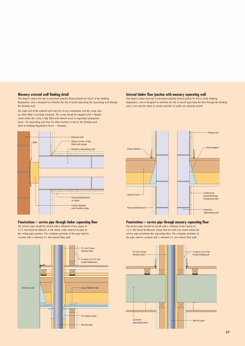
Masonry external wall flanking detail This detail is taken from the Government detailed Robust Details for Part E of the BuildingRegulations, and is designed to minimise the risk of sound bypassing the separating wall throughthe flanking wall.
The outer leaf of the external wall may be of any construction and the cavity may be either filled or partially insulated. The cavity should be stopped with a flexible closer unless the cavity is fully filled with mineral wool or expanded polystyrene bead. The separating wall may be either bonded or tied to the flanking wall (refer to Building Regulations Part A – Structure).
Internal timber floor junction with masonry separating wallThis detail is taken from the Government detailed Robust Details for Part E of the BuildingRegulations, and is designed to minimise the risk of sound bypassing the floor through the flankingwall. Care must be taken to ensure potential air paths are properly sealed.
Penetrations – service pipe through masonry separating floorThe service pipe should be boxed with a minimum of two layers of 12.5 mm Knauf Wallboard. Ensure that all voids are sealed where the service pipe penetrates the separating floor. The complete perimeter of the pipe must be covered with a minimum 25 mm mineral fibre quilt.
Penetrations – service pipe through timber separating floorThe service pipe should be boxed with a minimum of two layers of 12.5 mm Knauf Wallboard. A fire sleeve collar must be located at the ceiling pipe junction. The complete perimeter of the pipe must be covered with a minimum 25 mm mineral fibre quilt.
Knauf Sealant
Internal floor
Parge coat
Joist hangers
Continuous Knauf Bonding Compound dab
Masonry separating wall
Knauf plasterboard
2 layers 12.5 mmKnauf Wallboard
Service pipeConcreteseparating floor
25 mm Crown Partition Roll
25 mm Crown Partition Roll
Fire sleeve collar
Knauf Resilient Bar
Service pipe
External wall
2 layers of 12.5 mmKnauf Wallboard
Ensure corner is fullyfilled with parge
Cavity stoppedwith flexible closer
Knauf plasterboardon dabs
DPM
External wall
Masonry separating wall

HOUSING
28
STRUCTURE
Jamb for light doorSuitable for doors weighing up to 25 kg.
Jamb for medium weight doorSuitable for doors weighing up to 50 kg.
Jamb for heavy doorSuitable for doors weighing up to 75 kg.
Lightweight fixings parallel to surfaceSuitable for lightweight fixings where the applied load is fixed and continuous, to a maximum of 20 kg.
• Suggested applications: mirrors, pictures, light fixings, coat hooks.
Timber groundKnauf Drywall screws
Knauf plasterboard 150 mm max
Knauf Drywall anchor(not to scale)
Knauf plasterboard
Timber ground
Fully boxed Knauf C-studsKnauf Drywall screws
150 mm max
Timber ground
Knauf Drywall screws
Knauf plasterboard 150 mm max
Fully boxed Knauf C Studs
BEST PRACTICE DETAILING

29
Medium weight fixings parallel to surfaceSuitable for medium weight fixings where the applied load is fixed and continuous, and for lightweight fixings where the load may be subject to some movement (e.g. through removable objects).
• Suggested applications: radiators, curtain rails.
Heavyweight fixings parallel to surfaceSuitable for heavyweight fixings where the applied load is fixed and continuous, and for medium weight fixings where the load may be subject to some movement (eg. through removable objects), to a maximum of 40 kg/ lin.m.
• Suggested applications: bath (lateral location only), cupboards, shelving, handrails.
Heavyweight fixings parallel to surface at low level This is an alternative for use at low level where there may be a requirement for the partition to take a heavier than normal load to a maximum of 80 kg/ lin. m.
• Suggested applications: cupboards, basins, work surfaces.
Heavyweight fixings with momentFor use where the applied load is not directly adjacent to the board surface, thus producing a twisting force that the other fixing details are not capable of withstanding. It is also suitable for fixing items that are likely to receive rougher than usual treatment.
• Suggested applications: TV mounting arms, pay telephones and hoods, disabled grab rails.
Knauf fixing channel fixed to studs
Horizontal nogging ofsawn softwood to suitsize of studs, notched into studs and fixed to ends
Horizontal nogging and central stud of sawnsoftwood to suit size of studs, notched into studs and fixed to ends
25 mm
50 mm
50 mm
50 mm
50 mm
50 mm
25 mm
300 mmmin
25 x 25 mm Knauf Angle fixed to stud at 50 mm centres
Min. 18 mm ply sized to cover complete load-bearing area of the fixture
HOUSING
30
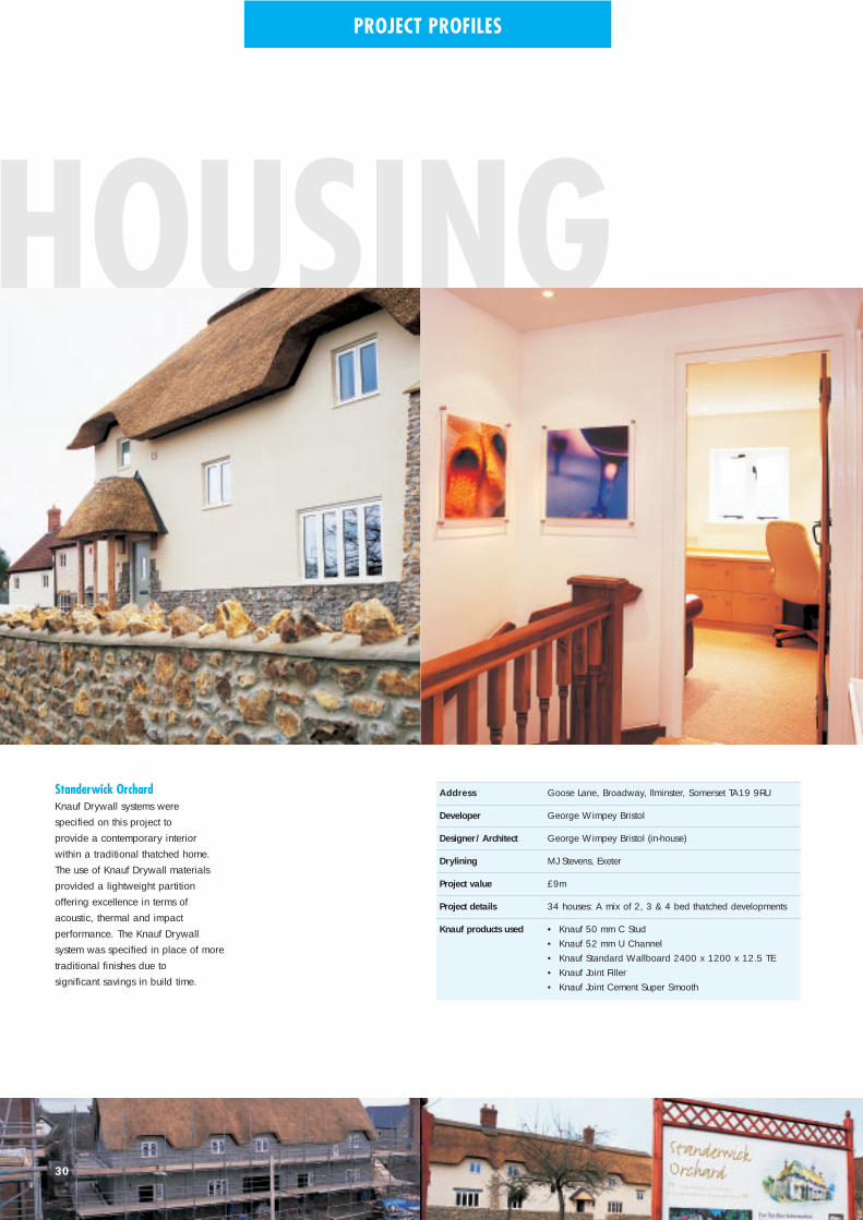
Address Goose Lane, Broadway, llminster, Somerset TA19 9RU
Developer George Wimpey Bristol
Designer/Architect George Wimpey Bristol (in-house)
Drylining MJ Stevens, Exeter
Project value £9m
Project details 34 houses: A mix of 2, 3 & 4 bed thatched developments
Knauf products used • Knauf 50 mm C Stud• Knauf 52 mm U Channel• Knauf Standard Wallboard 2400 x 1200 x 12.5 TE• Knauf Joint Filler• Knauf Joint Cement Super Smooth
Standerwick OrchardKnauf Drywall systems were specified on this project to provide a contemporary interior within a traditional thatched home.The use of Knauf Drywall materialsprovided a lightweight partition offering excellence in terms ofacoustic, thermal and impact performance. The Knauf Drywall system was specified in place of moretraditional finishes due tosignificant savings in build time.
PROJECT PROFILES

Address Vancouver Road, Turnford, Herts EN10 6FB
Developer Rialto
Designer/Architect Rialto/GHM
Drylining RPN, St Albans
Project value £31m
Project details 479 plots: 1 & 2 bed apartments, 3 & 4 bed houses
Knauf products used • Knauf 50 mm C Stud• Knauf 52 mm U Channel• Knauf MF Ceiling System• Knauf Standard Wallboard 2400 x 1200 x 12.5/15 TE• Knauf Moistureshield 2400 x 1200 x 12.5 TE• Knauf Fireshield 2400 x 1200 x 15 TE• Knauf Bonding Compound• Knauf Joint Filler• Knauf Joint Cement Super Smooth
Canada FieldsKnauf Drywall systems have beeninstalled throughout this prestige development of properties rangingfrom single bed apartments to fourbedroom houses.
Not only do Knauf Drywall systemsmeet the very high aesthetic criteriarequired for the decorative finish, but the use of performance-specificboards have allowed the constructionto meet the various Building
31
Regulations governing fire, thermal and acoustic requirements.Furthermore, the precision of metalstud and MF Ceiling systems minimises waste, whilst maximisingaccuracy and speed of installation.

Further information is contained within
The Complete Drywall Manual, available
online at our award winning website:
www.knaufdrywall.co.uk/themanual
together with a range of interactive tools
to aid the specifier and contractor.
Customer Service
Freephone: 0800 521 050
Freefax: 0800 521 205
E-mail: [email protected]
Technical Service
Tel: 01795 416 259
Literature
Tel: 08700 613 700
Website
www.knaufdrywall.co.uk
Knauf Drywall
PO Box 133
Sittingbourne
Kent ME10 3HW
Tel: (01795) 424 499
Fax: (01795) 428 651
Knauf Drywall Factory
Locations
Ridham Dock
Sittingbourne
Kent
Queens Road
Immingham
N.E. Lincolnshire
© Copyr ight Knauf Dr ywal l 2004
The information given in this document is believed to be current and accurate as at the date of publication, but no warranty expressor implied is given. Updates will not be automatically issued.
As part of our policy of continuous product development, we reservethe right to revise specifications without notice. The informationgiven in this publication is provided for guidance only and is correct to the best of our knowledge and belief. It is inevitablygeneralised and users should satisfy themselves as to the suitabilityfor the specific circumstances in which they seek to apply it.
December 2004Ref: SB1 - 01


