
D6.4.1 Risk Management report Version: v4 – Final, Date: 28/02/2014
Project Title: SIFEM Contract No. FP7-‐600933
Project Coordinator: National University of Ireland, Galway www.SIFEM-‐
project.eu
Page 1 of 41
SIFEM FP7-‐ICT-‐2011-‐9-‐600933
Semantic Infostructure interlinking an open source Finite Element tool and libraries with a model repository for the multi-scale Modelling and 3d
visualization of the inner-ear
Deliverable D6.4.1 Risk Management report
Responsible Partner: Institute of Communications and Computer Systems (ICCS)
Status-‐Version: Final
Date: 28/02/2014
EC Distribution: Public

D6.4.1 Risk Management report Version: v4 – Final, Date: 28/02/2014
Project Title: SIFEM Contract No. FP7-‐600933
Project Coordinator: National University of Ireland, Galway www.SIFEM-‐
project.eu
Page 2 of 41
Project Number: FP7-‐600933
Project Title: SIFEM
Title of Deliverable: Risk Management report
Date of Delivery to the EC: 28/02/2014
Work-‐package responsible for the Deliverable: WP6 – SIFEM Infrastructure Integration
Main Editor(s): ICCS
Contributor(s): ICCS, ISVR, UCL, BioIRC, RTV, INTRASOFT, DERI
Reviewer(s): INTRASOFT
Approved by: All Partners
Abstract: This document constitutes the deliverable D6.4.1 Risk Management report. The objective of this document is to report identified risks and the appropriate contingency plans and mitigation actions. More specifically, this deliverable describes and identifies the (technically caused) hazards associated with each part of the system, estimate and evaluate the risks associated with these hazards, control these risks, and monitor the effectiveness of that control limitations. The description is based on the published protocol and standards in the area of system risk management.
Keyword List: Risk management, hazards, contingency plan, software risks, standards and protocols
Document revision history

D6.4.1 Risk Management report Version: v4 – Final, Date: 28/02/2014
Project Title: SIFEM Contract No. FP7-‐600933
Project Coordinator: National University of Ireland, Galway www.SIFEM-‐
project.eu
Page 3 of 41
Version Date Modifications Introduced
Modified by Modification Reason
1 28/01/2014 ICCS The Table of Contents (ToC) was formed and sent to all partners
2 11/02/2014 INTRASOFT, RTV Contribution form INTRASOFT and RTV
2.1 13/02/2014 ICCS Updated contribution from ICCS and document update
3 25/02/2014 ISVR Contribution and updated risks from ISVR
3.1 26/02/2014 BioIRC Contribution and updated risks from BioIRC
3.2 27/02/2014 ICCS Updated risks form ICCS and consolidated document
3.3 27/02/2014 DERI Contribution from DERI
4 28/02/2014 ICCS Final Version from ICCS

D6.4.1 Risk Management report Version: v4 – Final, Date: 28/02/2014
Project Title: SIFEM Contract No. FP7-‐600933
Project Coordinator: National University of Ireland, Galway www.SIFEM-‐
project.eu
Page 4 of 41
1 GUIDELINES
Overview
The following report denotes the deliverable D6.4.1 Risk Management report.
Prerequisites
D2.1 State of the Art: The research conducted during this deliverable is necessary to identify state of the art inner ear modelling techniques and identify the innovation of SIFEM.
D2.2 User Requirements and Data Availability Analysis: This deliverable recorded the requirements of the SIFEM users and guides activities that are undertaken during Task 2.4 System Architecture and Functional Specifications and reported in this D2.3 SIFEM System Architecture.
D2.3 SIFEM System Architecture: A detailed report providing a thorough description of the hardware and software components of the SIFEM system, together with their functionalities.
D3.1 Delivery of the SIFEM FEM Tool v1: First version of the software for the SIFEM Finite Element Modelling tool, which will integrate open source FE libraries and corresponding tools and service.
D4.1 Quantification of the fluid pathways in the cochlea: Report regarding the quantification of the compliant fluid pathways in the cochlea for the BC inner ear modelling.
Moreover, this deliverable takes into account the outcome of the meetings held up to now.
No Other Prerequisites are needed.
Responsibilities
Each technical partner that has responsibilities in the design and the development of a specific part of the SIFEM should clearly define the major hazards and risk that would be introduced by its software or hardware part. The Technical Manager would be responsible for the circulation of the ToC and final version of the consolidated deliverable.
This deliverable will expand in parallel to the development and research activities of the project and more risks will be identified and recorded in the second version of the deliverable.

D6.4.1 Risk Management report Version: v4 – Final, Date: 28/02/2014
Project Title: SIFEM Contract No. FP7-‐600933
Project Coordinator: National University of Ireland, Galway www.SIFEM-‐
project.eu
Page 5 of 41
Table of Contents
1 GUIDELINES ............................................................................................ 4
2 INTRODUCTION .................................................................................... 14
3 STATE OF THE ART OF RISK MANAGEMENT STANDARDS ..................... 16
4 RISK MANAGEMENT .............................................................................. 18
4.1 Introduction ............................................................................................................ 18
4.2 Risk Management Steps .......................................................................................... 19
5 SOFTWARE RISK MANAGEMENT ........................................................... 23
5.1 Software risk Management ...................................................................................... 23
5.1.1 Semantic Infostructure and Storage Capabilities ............................................... 23
5.1.2 Integrate the Semantic Infostructure stored RDF data with the LOD Cloud ...... 23
5.1.3 FEM models requests via the Search interface .................................................. 24
5.1.4 Incorporation of VPH models ............................................................................. 24
5.1.5 SIFEM facing technology replacement issues .................................................... 24
5.1.6 Semantic Annotation Tool Usage ....................................................................... 24
6 RISK ASSESSMENT ................................................................................ 29
6.1 Introduction ............................................................................................................ 29
6.2 Estimation of Risks .................................................................................................. 29
6.3 Measures ................................................................................................................. 30
6.4 Risk Assessment Steps ............................................................................................. 31
6.5 Risk Categories ........................................................................................................ 32
6.6 Risk Evaluation ........................................................................................................ 33
7 RISK CONTROLS AND EVALUATION OF RISK ACCEPTANCE ................. 34
8 CONCLUSIONS ...................................................................................... 41

D6.4.1 Risk Management report Version: v4 – Final, Date: 28/02/2014
Project Title: SIFEM Contract No. FP7-‐600933
Project Coordinator: National University of Ireland, Galway www.SIFEM-‐
project.eu
Page 6 of 41
List of Figures
Figure 1: Example of assessment of the identified risk according to its probability and severity levels ............................................................................................................................................................ 22
Figure 2: The probability of occurrence vs severity for risks ............................................................... 39

D6.4.1 Risk Management report Version: v4 – Final, Date: 28/02/2014
Project Title: SIFEM Contract No. FP7-‐600933
Project Coordinator: National University of Ireland, Galway www.SIFEM-‐
project.eu
Page 7 of 41
List of Tables
Table 1: The levels of probability and severity ................................................................................... 30
Table 2: Description of abbreviations ................................................................................................. 32

D6.4.1 Risk Management report Version: v4 – Final, Date: 28/02/2014
Project Title: SIFEM Contract No. FP7-‐600933
Project Coordinator: National University of Ireland, Galway www.SIFEM-‐
project.eu
Page 8 of 41
Definitions, acronyms and abbreviations
Acronym Title
Modelling
BM Basilar membrane
TM Tectorial membrane
RM Reissner’s membrane
OHCs Outer hair cells
IHC Inner hair cell
St Stereocilia
C Cortilymph
SV Scala vestibule
ST Scala tympani
SM Scala media
OC Organ of Corti
HC Hensen’s cell
DC Deiter’s cell
RL Reticular lamina
IS Inner sulcus
HS Hensen’s stripe
IP Inner pillar cell
OP Outer pillar cell
Mod Modiulus
BC Bone Conduction
ENT Ear, nose, and throat
OAE Otoacoustic emissions

D6.4.1 Risk Management report Version: v4 – Final, Date: 28/02/2014
Project Title: SIFEM Contract No. FP7-‐600933
Project Coordinator: National University of Ireland, Galway www.SIFEM-‐
project.eu
Page 9 of 41
DPOAE Distortion product otoacoustic emissions
CM Cochlear Microphonics
Other Methods and Processes
FE Finite Element
FEM Finite Element Method
SNHL Sensorineural hearing loss
PTA Percutaneous transluminal angioplasty
TTS Temporary threshold shift
RTAE Requirements and Technology Assessment Exercise
PACS Picture archiving and communication system
DICOM Digital Imaging and Communications in Medicine
2D Two dimensions
3D Three dimensions
Project Management
CB Consortium Board
CCB Change Control Board
CO Confidential, only for members of the consortium (including the Commission Services)
CR Change Request
D Demonstrator
DL Deliverable Leader
DM Dissemination Manager
DMS Document Management System
DoW Description of Work
Dx Deliverable (where x defines the deliverable identification number e.g. D1.1.1)

D6.4.1 Risk Management report Version: v4 – Final, Date: 28/02/2014
Project Title: SIFEM Contract No. FP7-‐600933
Project Coordinator: National University of Ireland, Galway www.SIFEM-‐
project.eu
Page 10 of 41
EC Ethical Committee
EM Exploitation Manager
EU European Union
FM Financial Manager
FP Framework Programme
MS-‐ Microsoft Corporation
MSx project Milestone (where x defines a project milestone e.g. MS3)
Mx Month (where x defines a project month e.g. M10)
O Other
P Prototype
PC Project Coordinator
PM Partner Project Manager
PO Project Officer
PP Restricted to other programme participants (including the Commission Services)
PU Public
QA Quality Assurance
QAP Quality Assurance Plan
QDF Quality Function Deployment
QM Quality Manager
R Report
RE Restricted to a group specified by the consortium (including the Commission Services)
RUP Rational Unified Process
s/w Software
STEP Standard Technology Evaluation Process

D6.4.1 Risk Management report Version: v4 – Final, Date: 28/02/2014
Project Title: SIFEM Contract No. FP7-‐600933
Project Coordinator: National University of Ireland, Galway www.SIFEM-‐
project.eu
Page 11 of 41
STM Scientific and Technical Manager
TL Task Leader
WP Work Package
WPL Work Package Leader
WPS Work Package Structure
D6.4.1 Risk Management report Version: v4 – Final, Date: 28/02/2014
Project Title: SIFEM Contract No. FP7-‐600933
Project Coordinator: National University of Ireland, Galway www.SIFEM-‐
project.eu
Page 12 of 41
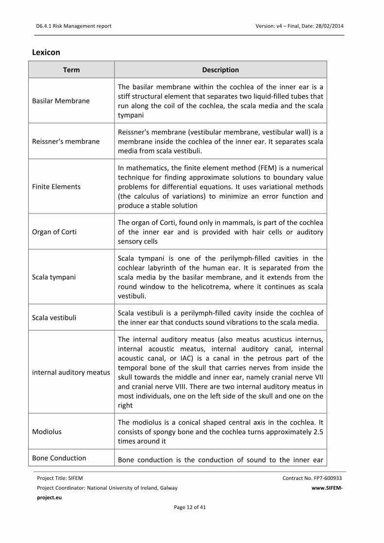
Lexicon
Term Description
Basilar Membrane
The basilar membrane within the cochlea of the inner ear is a stiff structural element that separates two liquid-‐filled tubes that run along the coil of the cochlea, the scala media and the scala tympani
Reissner's membrane Reissner's membrane (vestibular membrane, vestibular wall) is a membrane inside the cochlea of the inner ear. It separates scala media from scala vestibuli.
Finite Elements
In mathematics, the finite element method (FEM) is a numerical technique for finding approximate solutions to boundary value problems for differential equations. It uses variational methods (the calculus of variations) to minimize an error function and produce a stable solution
Organ of Corti The organ of Corti, found only in mammals, is part of the cochlea of the inner ear and is provided with hair cells or auditory sensory cells
Scala tympani
Scala tympani is one of the perilymph-‐filled cavities in the cochlear labyrinth of the human ear. It is separated from the scala media by the basilar membrane, and it extends from the round window to the helicotrema, where it continues as scala vestibuli.
Scala vestibuli Scala vestibuli is a perilymph-‐filled cavity inside the cochlea of the inner ear that conducts sound vibrations to the scala media.
internal auditory meatus
The internal auditory meatus (also meatus acusticus internus, internal acoustic meatus, internal auditory canal, internal acoustic canal, or IAC) is a canal in the petrous part of the temporal bone of the skull that carries nerves from inside the skull towards the middle and inner ear, namely cranial nerve VII and cranial nerve VIII. There are two internal auditory meatus in most individuals, one on the left side of the skull and one on the right
Modiolus The modiolus is a conical shaped central axis in the cochlea. It consists of spongy bone and the cochlea turns approximately 2.5 times around it
Bone Conduction Bone conduction is the conduction of sound to the inner ear

D6.4.1 Risk Management report Version: v4 – Final, Date: 28/02/2014
Project Title: SIFEM Contract No. FP7-‐600933
Project Coordinator: National University of Ireland, Galway www.SIFEM-‐
project.eu
Page 13 of 41
through the bones of the skull. Bone conduction transmission can be used with individuals with normal or impaired hearing
Stereocilia
In the inner ear, stereocilia are the mechanosensing organelles of hair cells, which respond to fluid motion in numerous types of animals for various functions, including hearing and balance. They are about 10–50 micrometers in length and share some similar features of microvilli.
Hair cells
Hair cells are the sensory receptors of both the auditory system and the vestibular system in all vertebrates. In mammals, the auditory hair cells are located within the organ of Corti on a thin basilar membrane in the cochlea of the inner ear.

D6.4.1 Risk Management report Version: v4 – Final, Date: 28/02/2014
Project Title: SIFEM Contract No. FP7-‐600933
Project Coordinator: National University of Ireland, Galway www.SIFEM-‐
project.eu
Page 14 of 41
2 INTRODUCTION The following report denotes the draft version of the deliverable D6.4.1 Risk Management report. The deliverable describes and identifies the (technically caused) hazards associated with software development, estimate and evaluate the risks associated with these hazards, control these risks, and monitor the effectiveness of that control limitations. The description is based on the published protocol and standards in the area of system risk management.
The safety of any medical software system is dependent on the application of a disciplined, well-‐defined, risk management process throughout the product life cycle. Hardware, software, human, and environmental interactions must be assessed in terms of intended use, risk, and cost/benefit criteria.
Risk analysis is employed by any medical software company and is responsible for all new and existing medical hardware/software developed. All hardware/software developed must be proven to be safe and efficient core to safe hardware/software is the hazard analysis and risk management process.
This report addresses these issues in SIFEM Platform hardware and software. Risk Analysis identifies the risks and potential obstacles to the future exploitation of a project's results.
The structure of the description of each component follows the ISO standard for risk management reports.
In our approach we used the ISO 149711: “Medical devices -‐ Application of risk management to medical devices” standard. This International Standard was developed specifically for medical device/system manufacturers using established principles of risk management. It could also be used as informative guidance in developing and maintaining a risk management system and process.
Each partner establishes documents and maintains throughout the life-‐cycle an on-‐going process for identifying hazards associated with a medical device, estimating and evaluating the associated risks, controlling these risks, and monitoring the effectiveness of the controls. This process shall include (1) risk analysis, (2) risk evaluation, (3) risk control and (4) production and post-‐production information.
Each partner within the consortium had to follow this specific methodology in order to make a complete risk analysis about the module they had to develop. The results were collected and analyzed and the outcome was a universal risk analysis report.
1 http://www.iso.org/iso/catalogue_detail?csnumber=38193

D6.4.1 Risk Management report Version: v4 – Final, Date: 28/02/2014
Project Title: SIFEM Contract No. FP7-‐600933
Project Coordinator: National University of Ireland, Galway www.SIFEM-‐
project.eu
Page 15 of 41

D6.4.1 Risk Management report Version: v4 – Final, Date: 28/02/2014
Project Title: SIFEM Contract No. FP7-‐600933
Project Coordinator: National University of Ireland, Galway www.SIFEM-‐
project.eu
Page 16 of 41
3 STATE OF THE ART OF RISK MANAGEMENT STANDARDS Healthcare Failure Modes and Effects Analysis2 (HFMEA) has been designed by the VA National Centre for Patient Safety3 (NCPS) specifically for healthcare. HFMEA streamlines the hazard analysis steps found in the traditional Failure Modes and Effects Analysis (FMEA) process by combining the detectability and criticality steps of the traditional FMEA into an algorithm presented as a Decision Tree. It also replaces calculation of the risk priority number (RPN) with a hazard score that is read directly from the Hazard Matrix Table. This table was developed by NCPS specifically for this purpose.
Healthcare FMEA Steps
1. Define the HFMEA Topic -‐ Define the topic of the Healthcare FMEA along with a clear definition of the process to be studied
2. Assemble the Team -‐ The team is to be multidisciplinary including Subject Matter Expert(s) and an advisor
3. Graphically Describe the Process 4. Conduct a Hazard Analysis 5. Actions and Outcome Measures
Root cause analysis4 (RCA) is a class of problem solving methods aimed at identifying the root causes of problems or events. The practice of RCA is predicated on the belief that problems are best solved by attempting to address, correct or eliminate root causes, as opposed to merely addressing the immediately obvious symptoms. By directing corrective measures at root causes, it is more probable that problem recurrence will be prevented. However, it is recognized that complete prevention of recurrence by one corrective action is not always possible. Conversely, there may be several effective measures (methods) that address the root cause of a problem. Thus, RCA is often considered to be an iterative process, and is frequently viewed as a tool of continuous improvement.
RCA is typically used as a reactive method of identifying event(s) causes, revealing problems and solving them. Analysis is done after an event has occurred. Insights in RCA may make it useful as a pro-‐active method. In that event, RCA can be used to forecast or predict probable events even before they occur. While one follows the other, RCA is a completely separate process to Incident Management.
Root cause analysis is not a single, sharply defined methodology; there are many different tools, processes, and philosophies for performing RCA analysis. However, several very-‐broadly defined approaches or "schools" can be identified by their basic approach or field of origin: safety-‐based, production-‐based, process-‐based, failure-‐based, and systems-‐based.
2 http://www.whaqualitycenter.org/Portals/0/Tools%20to%20Use/Collecting%20Data%20and%20Information/HFMEA%20Steps.pdf 3 http://www.patientsafety.va.gov/ 4 http://www.ncbi.nlm.nih.gov/pmc/articles/PMC1292997/
D6.4.1 Risk Management report Version: v4 – Final, Date: 28/02/2014
Project Title: SIFEM Contract No. FP7-‐600933
Project Coordinator: National University of Ireland, Galway www.SIFEM-‐
project.eu
Page 17 of 41
Context about regulation and standards
The specific need for the creation and the development of such standard is the requirement for a presentation of documentation for the maintenance of quality assurance and manage risk in the area of medical devices.
ISO 9001: 2000 The International Organization for Standardization (ISO) provide the first version of a non-‐industry-‐specific quality system standard (ISO 9001) in the mid 1980s. Its update version ISO 9001:1994 became the leading standard for quality systems worldwide. The draft version of this specific standard includes the ISO 13485: 1996. The main advantage of the final updated version of ISO 13485: 2003 was its harmonization with the medical device regulatory requirements for quality management systems. Additionally, it includes features as continuous improvement and customer satisfaction that were not contained in documentation for the regulation of medical device industry.
ISO 13485: 2003 is an international standard that specifies requirements for a quality management system where an organization needs to demonstrate its ability to provide medical devices and related services that consistently meet customer and regulatory requirements applicable to medical devices and related services. The introduction of the revised ISO 13485 standard in 2003 marked the shift from procedure-‐based to process-‐based quality management systems. Process-‐based standards can be viewed as a continuum of activities, inputs and outputs that become the inputs of the next activity, whereas a procedure-‐based system considers the quality system in parts or separate functions, such as design control, production and process control. A common issue of the ISO 13485: 2003 standard is the initial development to product realization and the quality of the organization assesses and manages risk. A main document that is referred for the risk assessment is ISO 14971: 2007—Medical devices – Application of risk management to medical devices.
ISO 14971: 2007 document is not a simple guidance text including requirements but it includes recommendations that should be followed by the manufactures considering their applicability during the design and the development of the product. Identification and traceability also is an important theme, in terms of product lots or batches, which carry with them supporting identification markings and records throughout the process. The ability to finely tuning is a significant value to any medical device company. Actually this is the main goal of the Risk management process. Its clear role is “process for a manufacturer to identify the hazards associated with medical devices, including in vitro diagnostic medical devices, to estimate and evaluate the associated risks, to control these risks and to monitor the effectiveness of the controls.”
Risk management is a crucial part to effective quality assurance systems because justification for quality system decisions should be documented based on risk. Risk often is evaluated from two perspectives: safety risk and business risk. Safety risks are analyzed based on the class of medical product and the intrinsic risk that it poses. For this component, safety risk can be described as likeliness of resulting in serious injury or death or as causing harm.

D6.4.1 Risk Management report Version: v4 – Final, Date: 28/02/2014
Project Title: SIFEM Contract No. FP7-‐600933
Project Coordinator: National University of Ireland, Galway www.SIFEM-‐
project.eu
Page 18 of 41
4 RISK MANAGEMENT
4.1 INTRODUCTION There are a variety of risk analysis techniques available these days. Each has its strengths and weakness, depending on the needs and practices of the project team. So, selecting the right technique is essential.
All of these techniques involve identifying and prioritizing the risks to the quality of the system under test. Typically, the risks are grouped or organized by major risk categories, such as functionality, performance, security, and so forth. A cross-‐functional team of project stakeholders usually identifies the risks. Rather than rely only on the stakeholders’ opinions and recollections, the analysis should also draw upon historical bug and field failure data from past projects, requirements and design specifications, sales figures, market research, and anecdotal information from customers, competitors, or clients.
In our approach we used the ISO 14971: “Medical devices -‐ Application of risk management to medical devices” standard. This International Standard was developed specifically for medical device/system manufacturers using established principles of risk management. It could also be used as informative guidance in developing and maintaining a risk management system and process.
It deals with processes for managing risks, primarily to the patient, but also to the operator, other persons, other equipment and the environment.
As a general concept, activities in which an individual, organization or government is involved can expose those or other stakeholders to hazards which can cause loss of or damage to something they value. Risk management is a complex subject because each stakeholder places a different value on the probability of harm occurring and its severity.
It is accepted that the concept of risk has two components:
a) The probability of occurrence of harm;
b) The consequences of that harm, that is, how severe it might be.
The concepts of risk management are particularly important in relation to medical devices because of the variety of stakeholders including medical practitioners, the organizations providing health care, governments, industry, patients and members of the public. All stakeholders need to understand that the use of a medical device entails some degree of risk. The acceptability of a risk to a stakeholder is influenced by the components listed above and by the stakeholder’s perception of the risk. Each stakeholder’s perception of the risk can vary greatly depending upon their cultural background, the socio-‐economic and educational background of the society concerned, the actual and perceived state of health of the patient, and many other factors. The way a risk is perceived also takes into account, for example, whether exposure to the hazard seems to be involuntary, avoidable, from a man-‐made source, due to negligence, arising from a poorly understood cause, or directed at a vulnerable group within society. The decision to use a medical device in the context of a particular clinical procedure requires the residual risks to be balanced against the anticipated benefits of the procedure. Such judgments should take into account the intended use, performance and risks associated with the medical device, as well as the risks and benefits associated with the

D6.4.1 Risk Management report Version: v4 – Final, Date: 28/02/2014
Project Title: SIFEM Contract No. FP7-‐600933
Project Coordinator: National University of Ireland, Galway www.SIFEM-‐
project.eu
Page 19 of 41
clinical procedure or the circumstances of use. Some of these judgments can be made only by a qualified medical practitioner with knowledge of the state of health of an individual patient or the patient’s own opinion.
As one of the stakeholders, the manufacturer makes judgments relating to safety of a medical device, including the acceptability of risks, taking into account the generally accepted state of the art, in order to determine the suitability of a medical device to be placed on the market for its intended use. This International Standard specifies a process through which the manufacturer of a medical device can identify hazards associated with a medical device, estimate and evaluate the risks associated with these hazards, control these risks, and monitor the effectiveness of that control.
4.2 RISK MANAGEMENT STEPS Each partner establishes documents and maintains throughout the life-‐cycle an ongoing process for identifying hazards associated with a medical device, estimating and evaluating the associated risks, controlling these risks, and monitoring the effectiveness of the controls. This process shall include the following elements:
• risk analysis
• risk evaluation
• risk control
• production and post-‐production information
A schematic representation of the risk management process is shown in Figure 1. Depending on the specific life-‐cycle phase, individual elements of risk management can have varying emphasis. Also, risk management activities can be performed iteratively or in multiple steps as appropriate to the medical device. Annex B contains a more detailed overview of the steps in the risk management process. Compliance is checked by inspection of appropriate documents.

D6.4.1 Risk Management report Version: v4 – Final, Date: 28/02/2014
Project Title: SIFEM Contract No. FP7-‐600933
Project Coordinator: National University of Ireland, Galway www.SIFEM-‐
project.eu
Page 20 of 41
Figure 1: Risk management process
Each partner within the consortium had to follow this specific methodology in order to make a complete risk analysis about the module they had to develop. The results were collected and analyzed and the outcome was a universal risk analysis report.
The consortium compiled documentation on known and foreseeable hazards associated with the medical device in both normal and fault conditions.
During the risk analysis the factors that should be recorded are:
1. Module within the hazardous situation may occur
2. Function of the module
3. Identification of the hazardous situation
4. What caused the hazard

D6.4.1 Risk Management report Version: v4 – Final, Date: 28/02/2014
Project Title: SIFEM Contract No. FP7-‐600933
Project Coordinator: National University of Ireland, Galway www.SIFEM-‐
project.eu
Page 21 of 41
5. What is expected to be the effect of the hazard
6. Estimation of the probability and severity for the hazard
7. Measures that should be taken
8. Type of measure that manages a hazard
• Safety by Design
• Instructions for Use (Manual)
• Training
• Defect prevention
• Software Testing
• Service Manual
• Label/symbol
• Instructions for Service
The risk management process will be ratified through an iterative cycle of risks identification and evaluation as well as their respective controls. To successfully accomplish this process a horizontal activity has been inserted to the lifecycle of the SIFEM project (Task 6.6 Technical Risk Management) starting from M13 and extended to the rest of the project duration in order to ensure the proper risk identification, analysis and control through each phase of system implementation. The risk management is supported by a risk analysis document, which will be regularly updated following the development process. Each partner estimates and evaluates the associated risks, the respective controls, and monitors the effectiveness of the controls. This process will include the following elements:
• Risk analysis: Identify the risks according to their probability and severity and classify them to three main categories:
o General and administrative project risks
o Technical and scientific related risks
o Exploitation and outreach risks
• Risk evaluation: Risk evaluation determines the quantitative and qualitative values of risk related to a concrete situation or a recognized hazard. Each partner contributes to the risk assessment process by the definition and the identification of the different kind of risks and hazards that might be generated by a specific module of the SIFEM platform. The collection and classification of the risks needs specific description and formulation in a unique matrix for each subsystem/module in order to be feasible their systematic analysis.
The risk, will be considered as low for 1-‐7 (green), medium for 8-‐14 (yellow) and high 15-‐30 (red). The axes (Figure 1) include the severity level and the probability level (for simplicity rating from 1 to 4).

D6.4.1 Risk Management report Version: v4 – Final, Date: 28/02/2014
Project Title: SIFEM Contract No. FP7-‐600933
Project Coordinator: National University of Ireland, Galway www.SIFEM-‐
project.eu
Page 22 of 41
Figure 1: Example of assessment of the identified risk according to its probability and severity
levels
• Risk Control: Specify the contingency plan for each risk and the respective control/action that should be taken to eliminate the severity or probability of risk.
6 6 12 18 24 30
5 5 10 15 20 25
4 4 8 12 16 20
3 3 6 9 12 15
2 2 4 6 8 10
1 1 2 3 4 5
1 2 3 4 5
Prob
ability of O
ccurance (P
)
Severity (S)

D6.4.1 Risk Management report Version: v4 – Final, Date: 28/02/2014
Project Title: SIFEM Contract No. FP7-‐600933
Project Coordinator: National University of Ireland, Galway www.SIFEM-‐
project.eu
Page 23 of 41
5 SOFTWARE RISK MANAGEMENT
5.1 SOFTWARE RISK MANAGEMENT
5.1.1 Semantic Infostructure and Storage Capabilities A basic service offered by the Semantic Infostructure is related to storing image file data (such as micro-‐CT images) as well as RDF data either a) from data extracted from image metadata or b) RDFized FEM models. This fundamental capability is the basis of all tools that are included in SIFEM platform including the Annotator Tool, the Search Tool etc.
A potential risk that exists refers to the ability of the platform to store the increasing number of data, after its long time usage. This in turn refers to the disk space that is required to handle all such data in the pilots’ site. The severity and occurrence of such a case can be quite high, the resolvance however of the issue is straightforward and includes the usage of larger disk space, as well as incorporating compression algorithms.
5.1.2 Integrate the Semantic Infostructure stored RDF data with the LOD Cloud One of the most important services that run in the background is the Linking Component that allows RDF instances included in SIFEM repositories to be integrated with other external resources of public RDF entities that might exist the Linked Open Data cloud. This allows data that are not maintained or curated by people participating in SIFEM, to be brought “closer” to our platform to be used in analysis, help a user extend his understanding for a disease etc.
However useful this process of linking is, it does suffer from various problems that are not manageable by SIFEM developer or pilots. The problem in linking data is a multi-‐faceted one, with the basic aspects being the following:
a) data quality can be rather low, either in terms of the ontologies used, or even the way some ontologies might be used
b) the availability of these data via SPARQL points is not stable, with the HTTP 404 being the norm c) the variation of data existing in such is not large

D6.4.1 Risk Management report Version: v4 – Final, Date: 28/02/2014
Project Title: SIFEM Contract No. FP7-‐600933
Project Coordinator: National University of Ireland, Galway www.SIFEM-‐
project.eu
Page 24 of 41
For all the above reasons, one can understand that the occurrence and severity of this risk can be high. The measure that can be taken for this action is to investigate other more generic and well curated repositories that can be used (such as the case of DBpedia), as well as investigate the possibility of incorporating data from within SIFEM (such as extracted knowledge from partners papers).
5.1.3 FEM models requests via the Search interface Another important feature of the platform regards searching SIFEM related data (either images, RDF FEM models etc). The basis of this capability is the SPARQL query processing that is created via a User Interface that allows a user to graphically request data and receive the results.
One of the main issues that might occur refers to the actual usage of the interface to request data. The user might not be able to handle such a tool to find what s/he needs. We do consider this risk however of low occurrence, since there the interface is created in collaboration with the pilots, as well as there is the intention of creating a manual that will help train the user in the whole platform.
5.1.4 Incorporation of VPH models SIFEM is a project that acknowledges the importance of connecting to the VPH community either by promoting its own software in the VPH Network-‐of-‐Excellence (NoE) Community, or re-‐using tools, data and models. However, apart from contributing our code, the re-‐usability of things from VPH NoE might not be able to perform such a task, as models or data from VPH might not be related to SIFEM. The occurrence and the severity is quite high, however the SIFEM Consortium will try and resolve this by a) aligning our SIFEM Concept Model with other open ontologies that are related to VPH, and b) providing ETL processes that can help convert tools to models in VPH and vice-‐versa.
5.1.5 SIFEM facing technology replacement issues The project incorporates a great number of technologies that are of standard use and are considered to be state-‐of-‐the-‐art in terms of data management, services composition etc. However, there exists a risk of these technologies to be outdated by the end of the project, resulting in a system that a community (such as an open source one) might not be able to extend. The severity and occurrence of such a situation can be rather high, resulting in a project that will not survive the face of time.
Our approach to deal with this problem, is to keep up with the latest technologies as well as making all tools as modular as possible, that minimizing the chances of having large pieces of software becoming obsolete in the future.
5.1.6 Semantic Annotation Tool Usage This tool is responsible for allowing a user to annotate more knowledge to a data entity, thus extending its capabilities to appear in search results. This however, suffers from a problem of mis-‐annotating the data, thus resulting in situations that data appear in search result, when they should not. The severity and occurrence of this can be rather high; however it is believed that it is a manageable situation, with the creation of manuals that will help train the user to avoid such situations.

D6.4.1 Risk Management report Version: v4 – Final, Date: 28/02/2014
Project Title: SIFEM Contract No. FP7-‐600933
Project Coordinator: National University of Ireland, Galway www.SIFEM-‐
project.eu
Page 25 of 41
5.1.7 PREPROCESSING AND MESHING
In pre-‐processing and meshing procedure of inner ear modeling there are several risks that should
be taken into account.
5.1.7.1 Pre – processing
The following risks are identified as significant for the successful inner ear modelling:
1. Complex geometry of the inner ear.
Inner ear is not always macro mechanical model. When only mechanical behavior of the inner ear
and cochlea is considered, the inner ear can be modelled with simplified geometry on one scale. If
active model of the cochlea is modelled then in the model Organ of Corti should be included, which
has several time smaller dimensions then the rest of the inner ear, so multi – scale approach is
necessary.
Figure 2: Inner ear structure (left) and Organ of Corti (right)
Organ of Corti consists of the many, very small and tiny inner hair cells and outer hair cell, which are
responsible for generation of the electrical current through exchange of the potential and
generation of impulses which goes to the brain. As a product of outer hair cells behavior generated
force is applied on basilar membrane, and affects mechanical behavior of the system, as a backward
feedback. For active model complex geometry and multi – scale modelling will be applied.
2. Inappropriate images obtained from CT and micro CT -‐ means images with poor resolution,
which cannot be properly segmented.
D6.4.1 Risk Management report Version: v4 – Final, Date: 28/02/2014
Project Title: SIFEM Contract No. FP7-‐600933
Project Coordinator: National University of Ireland, Galway www.SIFEM-‐
project.eu
Page 26 of 41
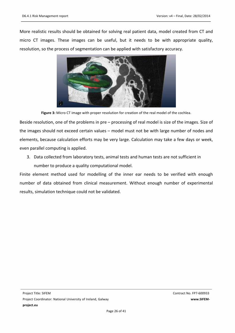
More realistic results should be obtained for solving real patient data, model created from CT and
micro CT images. These images can be useful, but it needs to be with appropriate quality,
resolution, so the process of segmentation can be applied with satisfactory accuracy.
Figure 3: Micro CT image with proper resolution for creation of the real model of the cochlea.
Beside resolution, one of the problems in pre – processing of real model is size of the images. Size of
the images should not exceed certain values – model must not be with large number of nodes and
elements, because calculation efforts may be very large. Calculation may take a few days or week,
even parallel computing is applied.
3. Data collected from laboratory tests, animal tests and human tests are not sufficient in
number to produce a quality computational model.
Finite element method used for modelling of the inner ear needs to be verified with enough
number of data obtained from clinical measurement. Without enough number of experimental
results, simulation technique could not be validated.

27
5.1.7.2 Meshing
1. Poor mesh quality on some segments.
In the certain parts of the model, where geometry is complex, tetrahedral mesh may not be correct.
In that case mesh should be checked and corrected manually.
Figure 4: Poor mesh quality in the curved shapes.
5.1.8 FEM SOLVER
Finite element method solver – PAK is used for modelling inner ear. First task in inner ear modelling
is to define appropriate mathematical model – equations which will represent system behavior with
certain correctness. Several approaches were tested in order to obtain the best agreement with
current analytical and experimental results. For mechanical model of the cochlea the best results
were obtained using fluid-‐structure strong coupling, with acoustic equation for modelling behavior
of the fluids in the chambers and Newtonian dynamics for modelling behavior of the basilar
membrane.
By using finite element methods there are several risks that may occur:
1. Convergence
28
One of the biggest issues in finite element method is definition of the convergence criteria. In PAK
solver for convergence criteria is used quotient of Euclidean norm of unknown variable increment
and Euclidean norm of the last known solution, from previous iteration. When this ratio is less that
given tolerance, convergence is achieved. In case of convergence problem, different criteria for
convergence should be implemented.
2. Too many nodes and elements.
Model should not be with large number of nodes and elements, because in that case calculations
will take too long, or will not be possible to perform. Models should not be simply, but they also
should not be with very fine mesh, especially in the areas that do not contribute too much to
solution. Optimal meshing algorithm should be implemented.
3. Implementation of the equations for the active model of the cochlea.
Finite element method software, PAK, should be adapted with equations for electrical model. There
can appear certain difficulties with electro – mechanical coupling or convergence. Then it should be
started from simplified model and then integration to more complex model.

29
6 RISK ASSESSMENT
6.1 INTRODUCTION The Grey – Box Diagrams split the architecture of a system, whose risks are analysed, in smaller blocks. The granularity of the blocks is a subjective decision, here is required to use the common sense and reduce the system architecture in a meaningful number of blocks.
Input and output describe the desired physical interaction that the system has with the environment. Immission and emission are the not desired physical interaction (e.g. disturbances) that the system get and release from and to the environment. For each of this block the possible risks must be analysed. Many of the risk found within one block will be also present in other blocks, or are treated (a measure is adopted) within other blocks, therefore it is meaningful to use references inside the risk table. The Grey-‐Box diagrams appeared in the Appendix I.
6.2 ESTIMATION OF RISKS
As we have already mentioned the concept of risk has two components: probability and severity. This does not mean that the two factors are multiplied to arrive at a risk value. One way to describe risk and to visualize the meaning of the definition could be done by a two-‐dimensional risk chart. Every single risk is given a score for its probability and severity. Once the risks are identified, each risk is assigned a level—a measure of its degree of importance.
The probability of harm should take into consideration the level or extent of exposure. This includes answering the following types of question.
• Does the hazardous situation occur in the absence of a failure?
• Does the hazardous situation occur in a fault condition?
• Does the hazardous situation occur only in a multiple-‐fault condition?
• How likely is it that a hazardous situation will lead to harm?
Table 1 demonstrates the point system we used to describe the levels of probability.
The normal condition of use is defined out of 1000 patients a year with a yearly use of 50 days.
OP
Occurrence probability
Definition Max cases per year
SD
Severity Degree
6 often
≥ 1 out of 100
500 5 catastrophic
5 probable
< 1 out of 100 and ≥ 1 out of 1.000
50 4 very critical
4 sporadic < 1 out of 1.000 and ≥ 1 out of 10.000
5 3 critical

30
3 remote
< 1 out of 10.000 and ≥ 1 out of 100.000
0.5 2 marginal
2 improbable < 1 out of 100.000 and ≥ 1 out of 1.000.000
0.05 1 insignificant
1 unlike < 1 out of 1.000.000
Risk evaluation
Acceptable range
Risk is low compared to the benefits. No action is required to reduce risk
Not acceptable range
Risk is not acceptable. Risk must be reduced to the acceptable range. If not, the benefit over
the risk must be explained.
Table 1: The levels of probability and severity
To categorize the severity of the potential harm, the manufacturer should use descriptors appropriate for the medical device. Estimating the severity of harm requires an understanding of the medical use of the IVD examination results, the analytical performance requirements for each application and the extent to which medical decisions are based on IVD examination results. For this reason, qualified medical input to the risk estimation process is essential. Severity is, in reality, a continuum. However, in practice, the use of a discrete number of severity levels simplifies the analysis. In such cases, the manufacturer decides how many categories are needed and how they are to be defined.
6.3 MEASURES For every risk we use one or more of the following risk control options in the priority order listed:
a) inherent safety by design b) protective measures in the medical device itself or in the manufacturing process c) information for safety
What is most important on measures we take is the following three factors

31
1. Implementation of each risk control measure is verified.
This verification is recorded in the risk management file. The effectiveness of the risk control measures is verified and the results are recorded in the risk management file.
2. Risk/benefit analysis If this evidence does not support the conclusion that the medical benefits outweigh the residual risk, then the risk remains unacceptable. If the medical benefits outweigh the residual risk, then the risk can be accepted.
3. Completeness of risk control The manufacturer shall ensure that the risk(s) from all identified hazardous situations have been considered. The results of this activity shall be recorded in the risk management file.
As we have already indicated risk management procedure contains a step during which measures are taken to eliminate the probability and severity of a risk. The measures are divided in 8 categories:
1. SbD Safety by Design
2. IfU Instructions for Use (Manual)
3. Tra training 4. DP Defect prevention
5. SwT Software Testing
6. SM Service Manual
7. Lbl Label/symbol
8. IfS Instructions for Service
6.4 RISK ASSESSMENT STEPS Risk assessment is a step in a risk management procedure. Risk assessment is the determination of quantitative or qualitative value of risk related to a concrete situation and a recognized hazard. Each partner contributes to the risk assessment process by the definition and the identification of the different kind of risks and hazards that might be generated by the specific module of the SIFEM platform. The collection and classification of the risks needs specific description and formulation in a unique matrix for each subsystem/module in order to be feasible their systematic analysis. The abbreviations that are utilized are reported in Table 2 and the collected matrixes are presented in Appendix.

32
Table 2: Description of abbreviations
Measure description of measure adopted
Standard Regulatory norm that applies
Type (of measure adopted): SbD: Safety by Design
IfU: Instructions for use (user manual)
Tra: Training
DP: Defect prevention
SwT: Software testing
SM: Service Manual
Lbl: Label/Symbol
IfS: Instructions for Service
Decision Yes if applied, No if not applied
Resp. Project partner responsible
Verification Type of document for the verification of the measure
OP Probability that the error occurs: 1 (low) to 6 (high)
SD Severity of the error / risk to users, patients and third parties: 1 (low) to 5 (high)
R Risk
N/A non-‐applicable or not relevant
# cause/effect ID in case refers to same hazard/cause
6.5 RISK CATEGORIES Risk analysis reports from every partner have been gathered and analyzed. Risks were initially separated according to whether they occur in hardware or software of the system. ISO standard 9621 describes the quality attributes found in software, provides a more structured approach and reduces the likelihood of missing some major risk elements. It follows industry-‐standard quality characteristics. In order to group the risks and make a complete report of the total risks we had to somehow group them. For ISO 9126 “quality risks analysis” techniques, one should use the quality characteristics and sub characteristics described in the ISO 9126 system quality standard as the categories for the risk analysis. The six main characteristics of quality are:
• Functionality
• Reliability

33
• Usability
• Efficiency
• Maintainability
• Portability
6.6 RISK EVALUATION The risk evaluation process is the establishment of a qualitative or quantitative relationship between risks and benefits, involving the complex process of determining the significance of the identified hazards and estimated risks to those organisms or people concerned with or affected by them. It is the first step in risk management and is synonymous with risk-‐benefit evaluation. In this stage the range of the risks could be defined as acceptable or not. In the case of the acceptable ranges the risk is low compared to the benefits and thus no actions are required to reduce the risk. On the other way, if the risk is not acceptable, the risk must be reduced to the acceptable range. If not, the benefit over the risk must be explained.
34
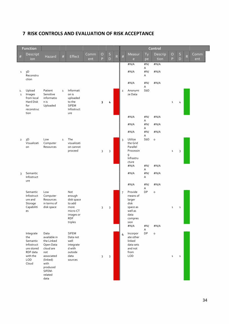
7 RISK CONTROLS AND EVALUATION OF RISK ACCEPTANCE
Function Control
# Descript
ion Hazard # Effect
Comment
OP
SD
R # Measur
e Type
Description
OP
SD
R Comment
0 #N/A #N/A
#N/A
0
1 3D Reconstruction
0 #N/A #N/A
#N/A
0
0 #N/A #N/A
#N/A
0
1.1
Upload Images from local Hard Disk for reconstruction
Patient Sensitive information is Uploaded
1 Information is uploaded to the SIFEM Infostructure
3 4
-1
2 Anonymize Data
SbD
1 4
1
0 #N/A #N/A
#N/A
0
0 #N/A #N/A
#N/A
0 0
0 #N/A #N/A
#N/A
0
2 3D Visualization
Low Computer Resources
1 The visualization cannot proceed
3 3
-1
3 Utilize the Grid Parallel Processing Infrastructure
SbD 0
1 3
1
0 #N/A #N/A
#N/A
0
3 Semantic Infostructure
0 #N/A #N/A
#N/A
0
0 #N/A #N/A
#N/A
0
Semantic Infostructure and Storage Capabilities
Low Computer Resources in terms of disk space
Not enough disk space to add more micro-‐CT images or RDF triples
3 3
-1
7 Provide means of larger disk space as well as data compression
DP 0
1 1
1
0 #N/A #N/A
#N/A
0
Integrate the Semantic Infostructure stored RDF data with the LOD Cloud
Data available in the Linked Open Data cloud are not associated (linked) with produced SIFEM-‐related data
SIFEM Data not well integrated with outside data sources
3 3
-1
4 Incorporate other linked data sets and not from LOD
DP 0
1 1
1

35
A user that is agnostic to the platform requests FEM models via the Search interface
Data are available, but user unable to request them due to not being able to understand the Search Interface
Will not receive the data of interest
1 4
1 1 Train the User
Tra 0
1 4
1
Incorporation of VPH models
Models from VPH NoE might mit be used
VPH Bridging will not proceed as required
3 3
-1
6 Provide means of ETL processes, ontology alignments
DP 0
0
SIFEM facing technology replacement issues
Technologies could be selected that might be outdated till the end of the project
Projects continuity after the end of funding, could be damaged
3 3
-1
5 Keeping up with latest libraries in all technologies
DP 0
1 1
1
User misuses the Semantic Annotation Tool
User has attached not relevant semantic annotations to an RDF entity
RDF entity might appear in search results that is not related too, thus confusing the search user
4 3
-1
1 Train the User
Tra 0
2 1
1
0
4 Inner ear
Modelling
0 #N/A #N/
A #N/A
0
0 #N/A #N/A
#N/A
0
MS4 is due in April 2014 (M14) and its verification is "Deliver a fully functional geometry model of the cochlea after gathering data in WP2, meshing and reconstruction the cochlea
Delay of work in WP3 and WP4
Canot achieve MS4 on time
The definition and meshing of the "full3D model" is not yet complete.
5 4
-1
2 Anonymize Data
SbD
1 1
1
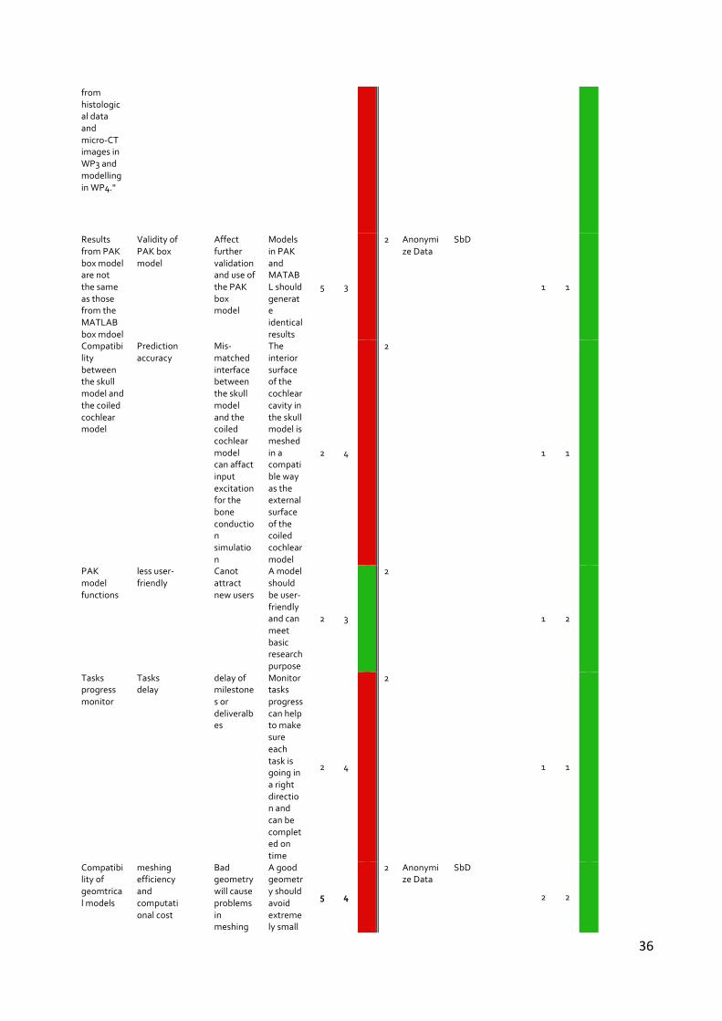
36
from histological data and micro-‐CT images in WP3 and modelling in WP4."
Results from PAK box model are not the same as those from the MATLAB box mdoel
Validity of PAK box model
Affect further validation and use of the PAK box model
Models in PAK and MATABL should generate identical results
5 3
-1
2 Anonymize Data
SbD
1 1
1
Compatibility between the skull model and the coiled cochlear model
Prediction accuracy
Mis-‐matched interface between the skull model and the coiled cochlear model can affact input excitation for the bone conduction simulation
The interior surface of the cochlear cavity in the skull model is meshed in a compatible way as the external surface of the coiled cochlear model
2 4
-1
2
1 1
1
PAK model functions
less user-‐friendly
Canot attract new users
A model should be user-‐friendly and can meet basic research purpose
2 3
1 2
1 2
1
Tasks progress monitor
Tasks delay
delay of milestones or deliveralbes
Monitor tasks progress can help to make sure each task is going in a right direction and can be completed on time
2 4
-1
2
1 1
1
Compatibility of geomtrical models
meshing efficiency and computational cost
Bad geometry will cause problems in meshing
A good geometry should avoid extremely small
5 4
-1
2 Anonymize Data
SbD
2 2
1

37
process or increase computational cost
structures.
0 #N/A #N/A
#N/A
0
the electrical model may not produce meaningful results
Although people have done electrical finite element modelling of the cochlea before, that has been in the context of cochlear implants rather than in the context of coupling of fields generated by hair cells in a cochlea that does not have an implant. Whether the lumped parameter model will apply to the finite element model is not yet known. A reason why it may not relate to the great difference between the size of the hair cells generating the fields,
3 5
-1
#N/A #N/A
#N/A
3 5
-1

38
and the cochlea structures through which the fields propagate.
0 #N/A #N/A
#N/A
0
3 Complex geometry
Inappropriate model
Calculation can not be performed
0 #N/A #N/A
#N/A
0
0 #N/A #N/A
#N/A
0
0 #N/A #N/A
#N/A
0
0 #N/A #N/A
#N/A
0
4 Size of the model
Too fine mesh, large number of nodes and elements
Calculation can not be performed
0 #N/A #N/A
#N/A
0
0 #N/A #N/A
#N/A
0
0 #N/A #N/A
#N/A
0
0 #N/A #N/A
#N/A
0
5 Insufficiently clinical data
Difficulties in measuring
FEM model can not be verified
0 #N/A #N/A
#N/A
0
0 #N/A #N/A
#N/A
0
0 #N/A #N/A
#N/A
0
0 #N/A #N/A
#N/A
0
6 Poor mesh quality
Required manual correction of the mesh
Calculation can not be performed
0 #N/A #N/A
#N/A
0
0 #N/A #N/A
#N/A
0
0 #N/A #N/ #N/A
0

39
A
0 #N/A #N/
A #N/A
0
7 Convergence
Inappropriate criteria
Calculation can not be performed
0 #N/A #N/A
#N/A
0
0 #N/A #N/A
#N/A
0
0 #N/A #N/A
#N/A
0
0 #N/A #N/A
#N/A
0
8 Electrical model in FEM
Difficulties for implementation
Lack of validation of the model
0 #N/A #N/A
#N/A
0
0 #N/A #N/A
#N/A
0
A way of applying acceptability criteria is by indicating in a matrix which combinations of probability of harm and severity of harm are acceptable or unacceptable. Such charts are usually specific to a product and its particular intended use. This matrix shows the number of hazards corresponding in each category. The horizontal axis indicates the level of severity from 1 to 5, while the vertical axis indicates the level of probability from 1 to 6. The green part indicates acceptable levels of risk while the red part indicates a hazardous situation for which measures are mandatory.
After merging the risks the outcome was really satisfying. We calculated a total of 14 risks. Below we can see 2 tables that demonstrate the risks.
Figure 5: The probability of occurrence vs severity for risks
Further analysis of the merged risks by category gives us a better picture of the risks that may occur in the system.

40
Modification of performance In the risk management procedure a further step is to re-‐calculate the probability and severity of a risk so a new table is created that shows these values after the measures have been taken.

41
8 CONCLUSIONS Risk analysis is a procedure that has many benefits for any system. The incredible wealth of information that risk analysis provides about the identified risk. Of course, is a cost-‐effective and a more in-‐depth, numerical approach to analyzing risk, which is something performed on risk to have a substantial impact on the project objectives. The additional information that risk analysis provides arms you with what you need to deal with them in the best way possible. And as one could imagine, risk analysis, as a result of the information we have obtained, increases the confidence level of controlling and dealing with risk. The risk management team is able to develop better decisions, more effective responses, as well as justify responses and recommendations made. Risk analysis involves looking at future impacts and decision-‐making. On that note, it allows us to control risk with greater success. SIFEM platform will be making much more informed and educated recommendations and responses. This increases the level of success that the risk response plan will have. Risk analysis helps to determine alternatives, if available, and notice that much of this provides supportive information. It is like having a little window to a risk that allows you to peek inside and shows you how the risk comes about and the damage or the opportunity that it can result it. Something else that should be mentioned is that risk deals heavily with uncertainty. Risk analysis aims at lessening this level of uncertainty by clarifying the impact and the potential outcomes. We can put together what seems like a solid schedule but there are always looming internal and external factors that can destroy our plans. Risk analysis is meant to help us foresee what could happen and prepare to deal with those scenarios. In conclusion risk analysis plays a central part of risk management. After the assessment and evaluation of the risks and the application of each measure the majority of the risk for software development, processes and user interaction were considered as acceptable. As for the conclusion we should notice that through the risk management process a researcher or a clinician has the opportunity to revise and identify the large majority of the risks and the hazards that exists with the inner ear modeling as well as the interaction with the SIFEM system. Although SIFEM platform is not a life-‐threatening system that might harm patients in a high degree or to become dangerous for his life, the risk management process is the essential process that aims at the improvement of the quality of the platform increasing its overall reliability.


