
ACETAL, POLYPROPYLENE, AND PVDF
Husky�1040 Air-OperatedDiaphragm Pumps
Acetal Model Shown
See Models on page 2 for a list of pump models and descriptions.
120 psi (0.8 MPa, 8 bar) Maximum Fluid Working Pressure120 psi (0.8 MPa, 8 bar) Maximum Air Input Pressure
Instructions – Parts List
308443Z2
Important Safety InstructionsRead all warnings and instructions in this manu-al. Save these instructions.
04155B
Patent No.CN ZL94102643.4FR 9408894JA 3517270US 5,368,452

2 308443
Table of ContentsModels 2. . . . . . . . . . . . . . . . . . . . . . . . . . . . . . . . . . . . . . . . Safety Warnings 3. . . . . . . . . . . . . . . . . . . . . . . . . . . . . . Installation 5. . . . . . . . . . . . . . . . . . . . . . . . . . . . . . . . . . . . . Operation 12. . . . . . . . . . . . . . . . . . . . . . . . . . . . . . . . . . . . Maintenance 13. . . . . . . . . . . . . . . . . . . . . . . . . . . . . . . . . . Troubleshooting 14. . . . . . . . . . . . . . . . . . . . . . . . . . . . . . . Service
Repairing the Air Valve 16. . . . . . . . . . . . . . . . . . . . . . Ball Check Valve Repair 18. . . . . . . . . . . . . . . . . . . . . Diaphragm Repair 19. . . . . . . . . . . . . . . . . . . . . . . . . . Bearing and Air Gasket Removal 22. . . . . . . . . . . . .
Pump Matrix 24. . . . . . . . . . . . . . . . . . . . . . . . . . . . . . . . . .
Repair Kit Matrix 25. . . . . . . . . . . . . . . . . . . . . . . . . . . . . . Parts 26. . . . . . . . . . . . . . . . . . . . . . . . . . . . . . . . . . . . . . . . Torque Sequence 30. . . . . . . . . . . . . . . . . . . . . . . . . . . . . Dimensional Drawings 31. . . . . . . . . . . . . . . . . . . . . . . . . Technical Data and Performance Chart 32. . . . . . . . . . . Graco Standard Warranty 34. . . . . . . . . . . . . . . . . . . . . . Graco Information 34. . . . . . . . . . . . . . . . . . . . . . . . . . . . .
Models
Model No. Description
*D71______ Acetal Pumps (see certification note below)
*D81______ Acetal Pumps, Remote (see certification note below)
*D72______ Polypropylene Pumps
*D82______ Polypropylene Pumps, Remote
*D75______ PVDF Pumps
*D85______ PVDF Pumps, Remote
*DR2______ Polypropylene Plus Pumps
*DS2______ Polypropylene Plus Pumps, Remote
*DR5______ PVDF Plus Pumps
*DS5______ PVDF Plus Pumps, Remote
24B754 PVDF Plus Pump with overmolded diaphragms
24B755 Polypropylene Plus Pump with overmolded diaphragms
24B756 Polypropylene Pump with overmolded diaphragms
24B757 Polypropylene Pump with overmolded diaphragms and sst seats
24B831 PVDF Pump with overmolded diaphragms
*NOTE: Refer to the Pump Matrix on page 24 to determine the Model No. of your pump.NOTE: Plus Models include stainless steel center sections.
CERTIFICATION NOTE: Acetal Pump Models D71______ and D81______ are certified.

308443 3
SymbolsWarning Symbol
WARNINGThis symbol alerts you to the possibility of seriousinjury or death if you do not follow the instructions.
Caution Symbol
CAUTIONThis symbol alerts you to the possibility of damage toor destruction of equipment if you do not follow theinstructions.
EQUIPMENT MISUSE HAZARD
Equipment misuse can cause the equipment to rupture or malfunction and result in serious injury.
� This equipment is for professional use only.
� Read all instruction manuals, tags, and labels before operating the equipment.
� Use the equipment only for its intended purpose. If you are not sure, call your Graco distributor.
� Do not alter or modify this equipment. Use only genuine Graco parts and accessories.
� Check equipment daily. Repair or replace worn or damaged parts immediately.
� Do not exceed the maximum working pressure of the lowest rated component in your system.This equipment has a 120 psi (0.8 MPa, 8 bar) maximum working pressure at 120 psi(0.8 MPa, 8 bar) maximum incoming air pressure.
� Use fluids and solvents which are compatible with the equipment wetted parts. Refer to theTechnical Data section of all equipment manuals. Read the fluid and solvent manufacturer’swarnings.
� Do not use hoses to pull equipment.
� Route hoses away from traffic areas, sharp edges, moving parts, and hot surfaces. Do not ex-pose Graco hoses to temperatures above 82�C (180�F) or below –40�C (–40�F).
� Do not lift pressurized equipment.
� Comply with all applicable local, state, and national fire, electrical, and safety regulations.
INSTRUCTIONS
WARNING

4 308443
TOXIC FLUID HAZARD
Hazardous fluid or toxic fumes can cause serious injury or death if splashed in the eyes or on theskin, inhaled, or swallowed.
� Know the specific hazards of the fluid you are using.
� Store hazardous fluid in an approved container. Dispose of hazardous fluid according to all local,state and national guidelines.
� Always wear protective eyewear, gloves, clothing and respirator as recommended by the fluidand solvent manufacturer.
� Pipe and dispose of the exhaust air safely, away from people, animals, and food handling areas.If the diaphragm fails, the fluid is exhausted along with the air. See Air Exhaust Ventilation onpage 11.
� To pump acids, always use a PVDF or a polypropylene pump. Take precautions to avoid acid oracid fumes from contacting the pump housing exterior. Stainless steel parts will be damaged byexposure to acid spills and fumes. Never use an acetal pump to pump acids.
FIRE AND EXPLOSION HAZARD
Improper grounding, poor ventilation, open flames or sparks can cause a hazardous condition andresult in a fire or explosion and serious injury.
� Ground the equipment. Refer to Grounding on page 6.
� Never use a polypropylene or PVDF pump with non-conductive flammable fluids as specified byyour local fire protection code. Refer to Grounding on page 6 for additional information. Consultyour fluid supplier to determine the conductivity or resistivity of your fluid.
� If there is any static sparking or you feel an electric shock while using this equipment, stoppumping immediately. Do not use the equipment until you identify and correct the problem.
� Provide fresh air ventilation to avoid the buildup of flammable fumes from solvents or the fluidbeing pumped.
� Pipe and dispose of the exhaust air safely, away from all sources of ignition. If the diaphragmfails, the fluid is exhausted along with the air. See Air Exhaust Ventilation on page 11.
� Keep the work area free of debris, including solvent, rags, and gasoline.
� Electrically disconnect all equipment in the work area.
� Extinguish all open flames or pilot lights in the work area.
� Do not smoke in the work area.
� Do not turn on or off any light switch in the work area while operating or if fumes are present.
� Do not operate a gasoline engine in the work area.
WARNING
308443 5
InstallationGeneral Information� The Typical Installation shown in Fig. 2 is only a
guide for selecting and installing system compo-nents. Contact your Graco distributor for assistancein planning a system to suit your needs.
� Always use Genuine Graco Parts and Accessories.
� Reference numbers and letters in parentheses referto the callouts in the figures and the parts lists onpages 26 to 27.
TOXIC FLUID HAZARDHazardous fluid or toxic fumes cancause serious injury or death if splashedin the eyes or on the skin, inhaled, orswallowed.
� Read TOXIC FLUID HAZARD on page 4.
� Use fluids and solvents that are compatible withthe equipment wetted parts. Refer to the Tech-nical Data section of all equipment manuals.Read the fluid and solvent manufacturer’swarnings.
WARNING
Tightening Screws Before First Use
Before using the pump for the first time, check andretorque all external fasteners. See Torque Se-quence, page 30. After the first day of operation,retorque the fasteners. Although pump use varies, ageneral guideline is to retorque fasteners every twomonths.
6 308443
InstallationGrounding
WARNINGFIRE AND EXPLOSION HAZARDThis pump must be grounded. Beforeoperating the pump, ground the systemas explained below. Also read the sec-tion FIRE AND EXPLOSION HAZARDon page 4.
The acetal pump contains stainless steel fiberswhich make the wetted parts conductive. Attachingthe ground wire to the grounding screw will groundthe air motor and the wetted parts.
The polypropylene and PVDF pumps are notconductive. Attaching the ground wire to thegrounding screw will ground only the air motor.When pumping conductive flammable fluids, al-ways ground the entire fluid system by makingsure the fluid system has an electrical path to atrue earth ground (see Fig. 2). Never use a poly-propylene or PVDF pump with non-conductiveflammable fluids as specified by your local fireprotection code.
US Code (NFPA 77 Static Electricity) recommendsa conductivity greater than 50 x 10–12 Siemans/me-ter (mhos/meter) over your operating temperaturerange to reduce the hazard of fire. Consult yourfluid supplier to determine the conductivity orresistivity of your fluid. The resistivity must be lessthan 2 x 10¹² ohm-centimeters.
To reduce the risk of static sparking, ground thepump and all other equipment used or located inthe pumping area. Check your local electrical codefor detailed grounding instructions for your areaand type of equipment.
Ground all of this equipment:
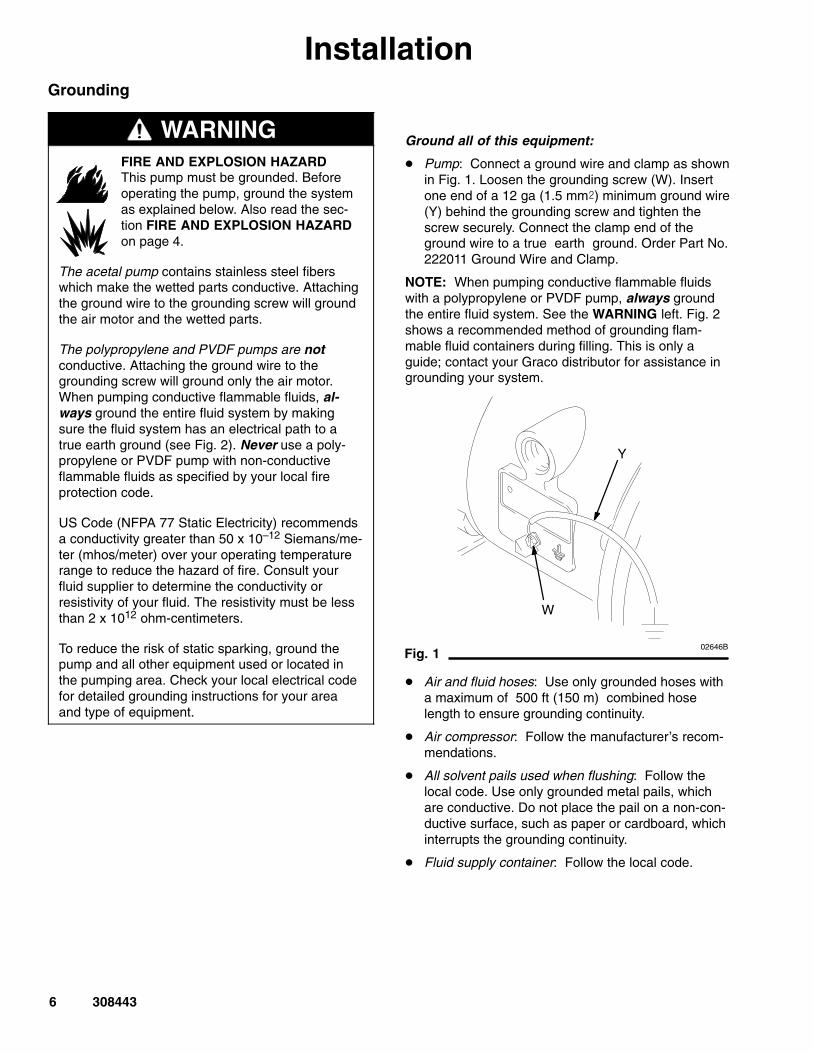
� Pump: Connect a ground wire and clamp as shownin Fig. 1. Loosen the grounding screw (W). Insertone end of a 12 ga (1.5 mm�) minimum ground wire(Y) behind the grounding screw and tighten thescrew securely. Connect the clamp end of theground wire to a true earth ground. Order Part No.222011 Ground Wire and Clamp.
NOTE: When pumping conductive flammable fluidswith a polypropylene or PVDF pump, always groundthe entire fluid system. See the WARNING left. Fig. 2shows a recommended method of grounding flam-mable fluid containers during filling. This is only aguide; contact your Graco distributor for assistance ingrounding your system.
02646B
Fig. 1
Y
W
� Air and fluid hoses: Use only grounded hoses witha maximum of 500 ft (150 m) combined hoselength to ensure grounding continuity.
� Air compressor: Follow the manufacturer’s recom-mendations.
� All solvent pails used when flushing: Follow thelocal code. Use only grounded metal pails, whichare conductive. Do not place the pail on a non-con-ductive surface, such as paper or cardboard, whichinterrupts the grounding continuity.
� Fluid supply container: Follow the local code.
308443 7
InstallationAir Line
WARNINGA bleed-type master air valve (B) is required inyour system to relieve air trapped between thisvalve and the pump. Trapped air can cause thepump to cycle unexpectedly, which could result inserious injury, including splashing in the eyes or onthe skin, injury from moving parts, or contaminationfrom hazardous fluids. See Fig. 2.
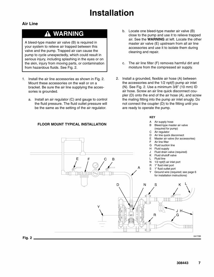
1. Install the air line accessories as shown in Fig. 2.Mount these accessories on the wall or on abracket. Be sure the air line supplying the acces-sories is grounded.
a. Install an air regulator (C) and gauge to controlthe fluid pressure. The fluid outlet pressure willbe the same as the setting of the air regulator.
b. Locate one bleed-type master air valve (B)close to the pump and use it to relieve trappedair. See the WARNING at left. Locate the othermaster air valve (E) upstream from all air lineaccessories and use it to isolate them duringcleaning and repair.
c. The air line filter (F) removes harmful dirt andmoisture from the compressed air supply.
2. Install a grounded, flexible air hose (A) betweenthe accessories and the 1/2 npt(f) pump air inlet(N). See Fig. 2. Use a minimum 3/8” (10 mm) IDair hose. Screw an air line quick disconnect cou-pler (D) onto the end of the air hose (A), and screwthe mating fitting into the pump air inlet snugly. Donot connect the coupler (D) to the fitting until youare ready to operate the pump.
KEY
A Air supply hoseB Bleed-type master air valve
(required for pump)C Air regulatorD Air line quick disconnectE Master air valve (for accessories)F Air line filterG Fluid suction lineH Fluid supplyJ Fluid drain valve (required)K Fluid shutoff valveL Fluid lineN 1/2 npt(f) air inlet portR 1” fluid inlet portS 1” fluid outlet portY Ground wire (required; see page 6
for installation instructions)
Fig. 2
FLOOR MOUNT TYPICAL INSTALLATION
YJ
F BE C
A
D K L
GH
R
SN
04170B
8 308443
InstallationMountings
CAUTIONThe pump exhaust air may contain contaminants.Ventilate to a remote area if the contaminantscould affect your fluid supply. See Air ExhaustVentilation on page 11.
1. Be sure the mounting surface can support theweight of the pump, hoses, and accessories, aswell as the stress caused during operation.
2. For all mountings, be sure the pump is bolteddirectly to the mounting surface.
3. For ease of operation and service, mount thepump so the air valve cover (2), air inlet, and fluidinlet and outlet ports are easily accessible.
4. Rubber Foot Mounting Kit 236452 is available toreduce noise and vibration during operation.
Installation of Remote Pilot Air Lines
1. Refer to Parts Drawings. Connect air line to pumpas in preceding steps.
2. Connect 1/4 in. O.D. tubing to push type connec-tors (14) on air motor of pump.
NOTE: by replacing the push type connectors, othersizes or types of fittings may be used. The new fittingswill require 1/8 in. npt threads.
3. Connect remaining ends of tubes to external airsignal, such as Graco’s Cycleflo (P/N 195264) orCycleflo II (P/N195265) controllers.
NOTE: the air pressure at the connectors must be atleast 30% of the air pressure to the air motor for thepump to operate.
Fluid Suction Line
� If using a conductive (Acetal) pump, use conductivehoses (G). If using a non-conductive (polypropy-lene or PVDF) pump, ground the fluid system. SeeGrounding on page 6.
� The pump fluid inlet (R) is a 1” raised face flange.See Flange Connections on page 9.
� If the fluid inlet pressure to the pump is more than25% of the outlet working pressure, the ball checkvalves will not close fast enough, resulting in ineffi-cient pump operation.
� At inlet fluid pressures greater than 15 psi(104 kPa, 1 bar), diaphragm life will be shortened.
� See the Technical Data on page 32 for maximumsuction lift (wet and dry).
Fluid Outlet Line
WARNINGA fluid drain valve (J) is required to relieve pres-sure in the hose if it is plugged. The drain valvereduces the risk of serious injury, including splash-ing in the eyes or on the skin, or contaminationfrom hazardous fluids when relieving pressure.Install the valve close to the pump fluid outlet. SeeFig. 2.
1. Use grounded fluid hoses (L). The pump fluidoutlet (S) is a 1” raised face flange. Refer toFlange Connections on page 9.
2. Install a fluid drain valve (J) near the fluid outlet.See the WARNING above.
3. Install a shutoff valve (K) in the fluid outlet line.

308443 9
InstallationFlange Connections
The fluid inlet and outlet ports are 1” raised faceflanges. Connect 1” flanged plastic pipe to the pumpas follows. You will need:
� Torque wrench
� Adjustable wrench
� One 4.25” diameter, 1/8” thick PTFE gasket, withfour 0.62 diameter holes and a 1.15” diametercenter
� Four 1/2” x 2.5” bolts
� Four 1/2” spring lockwashers
� Eight 1/2” flat washers
� Four 1/2” nuts.
1. Place a lockwasher and a flat washer on each bolt.Refer to Fig. 3.
2. Align the holes in the gasket and the pipe flangewith the holes in the pump flange.
3. Lubricate the threads of the four bolts. Install thebolts through the holes and secure with the wash-ers and nuts.
4. Hold the nuts with a wrench. Refer to the tighten-ing sequence in Fig. 3 and torque the bolts to10 to 15 ft-lb (14 to 20 N-m). Do not over-torque.
Fig. 3
1
04405
KEYA Flanged plastic pipeB PTFE gasketC BoltD LockwasherE Flat washerF NutR 1” fluid inlet flangeS 1” fluid outlet flange
A
B
C
DE
EF
S
R
Torque to 10 to 15 ft-lb (14-20 N-m).Do not over-torque.
1
2
3
4
1
BOLT TIGHTENING SEQUENCE
1
04404B

10 308443
InstallationChanging the Orientation of the Fluid Inletand Outlet Ports
The pump is shipped with the fluid inlet (R) and outlet(S) ports facing the same direction. See Fig. 4. Tochange the orientation of the inlet and/or outlet port:
1. Remove the screws (106 or 112) holding the inlet(102) and/or outlet (103) manifold to the covers(101).
2. Reverse the manifold and reattach. Install thescrews (106 or 112). Torque the manifold screwsto 80 to 90 in-lb (9 to 10 N-m). See Fig. 4. SeeTorque Sequence, page 30.
Fig. 4
1
KEY
N 1/2 npt(f) air inlet portP Muffler; air exhaust port
is 3/4 npt(f)R 1” fluid inlet portS 1” fluid outlet port
101 Covers102 Fluid inlet manifold103 Fluid outlet manifold106 Manifold screws112 Manifold screws
N
P
R
S
1
Acetal Model Shown
103
102
101
112
106
Torque to 80 to 90 in-lb (9 to 10 N-m).See Torque Sequence, page 30.
1
04155B
Fluid Pressure Relief Valve
Some systems may require installation of a pres-sure relief valve at the pump outlet to preventoverpressurization and rupture of the pump orhose. See Fig. 5.
Thermal expansion of fluid in the outlet line cancause overpressurization. This can occur whenusing long fluid lines exposed to sunlight or ambi-ent heat, or when pumping from a cool to a warmarea (for example, from an underground tank).
Overpressurization can also occur if the Huskypump is being used to feed fluid to a piston pump,and the intake valve of the piston pump does notclose, causing fluid to back up in the outlet line.
CAUTION
04228B
Fig. 5
1
2 Connect fluid inlet line here.
KEY
R 1” fluid inlet portS 1” fluid outlet portV Pressure relief valve
Part No. 112119 (stainless steel)
R
SConnect fluid outlet line here.
1
2
3
Install valve between fluid inlet and outlet ports.
V
3

308443 11
InstallationAir Exhaust Ventilation
FIRE AND EXPLOSION HAZARDBe sure to read FIRE OR EXPLOSIONHAZARD and TOXIC FLUID HAZARDon page 4, before operating this pump.
Be sure the system is properly ventilatedfor your type of installation. You must
vent the exhaust to a safe place, away from peo-ple, animals, food handling areas, and all sourcesof ignition when pumping flammable or hazardousfluids.
Diaphragm failure will cause the fluid beingpumped to exhaust with the air. Place an appropri-ate container at the end of the air exhaust line tocatch the fluid. See Fig. 6.
WARNING The air exhaust port is 3/4 npt(f). Do not restrict the airexhaust port. Excessive exhaust restriction can causeerratic pump operation.
To provide a remote exhaust:
1. Remove the muffler (P) from the pump air exhaustport.
2. Install a grounded air exhaust hose (T) and con-nect the muffler (P) to the other end of the hose.The minimum size for the air exhaust hose is 3/4in. (19 mm) ID. If a hose longer than 15 ft (4.57 m)is required, use a larger diameter hose. Avoidsharp bends or kinks in the hose. See Fig. 6.
3. Place a container (U) at the end of the air exhaustline to catch fluid in case a diaphragm ruptures.
Fig. 6
KEY
A Air supply lineB Bleed-type master air valve
(required for pump)C Air regulatorD Air line quick disconnectE Master air valve (for accessories)F Air line filterP MufflerT Grounded air exhaust hoseU Container for remote air exhaust
F BE C
A
D
VENTING EXHAUST AIR
P
TU
04168A

12 308443
OperationPressure Relief Procedure
PRESSURIZED EQUIPMENT HAZARDThe equipment stays pressurized until pressure ismanually relieved. To reduce the risk of seriousinjury from pressurized fluid, accidental spray fromthe gun or splashing fluid, follow this procedurewhenever you
� Are instructed to relieve pressure� Stop pumping� Check, clean, or service any system equipment� Install or clean fluid nozzles
WARNING
1. Shut off the air to the pump.
2. Open the dispensing valve, if used.
3. Open the fluid drain valve to relieve all fluid pres-sure, having a container ready to catch the drain-age.
Flush the Pump Before First Use
The pump was tested with lightweight oil, which is leftin the fluid passages to protect parts. To avoid contam-inating your fluid with oil, flush the pump with a com-patible solvent before using the equipment. Follow thesteps under Starting and Adjusting the Pump.
Starting and Adjusting the Pump
TOXIC FLUID HAZARDHazardous fluid or toxic fumes cancause serious injury or death if splashedin the eyes or on the skin, inhaled, or
swallowed. Do not lift a pump under pressure. Ifdropped, the fluid section may rupture. Always fol-low the Pressure Relief Procedure above beforelifting the pump.
WARNING
1. Be sure the pump is properly grounded. Refer toGrounding on page 6.
2. Check all fittings to be sure they are tight. Be sureto use a compatible liquid thread sealant on allmale threads. Tighten the fluid inlet and outletfittings securely.
3. Place the suction tube (if used) in the fluid to bepumped.
NOTE: If the fluid inlet pressure to the pump is morethan 25% of the outlet working pressure, the ball checkvalves will not close fast enough, resulting in inefficientpump operation.
4. Place the end of the fluid hose (L) into an appropri-ate container.
5. Close the fluid drain valve (J). See Fig. 2.
6. With the pump air regulator (C) closed, open allbleed-type master air valves (B, E).
7. If the fluid hose has a dispensing device, hold itopen while continuing with the following step.
8. Slowly open the air regulator (C) until the pumpstarts to cycle. Allow the pump to cycle slowly untilall air is pushed out of the lines and the pump isprimed.
If you are flushing, run the pump long enough tothoroughly clean the pump and hoses. Close theair regulator. Remove the suction tube from thesolvent and place it in the fluid to be pumped.

308443 13
OperationOperation of Remote Piloted Pumps
1. Follow preceding steps 1 through 7 of Startingand Adjusting Pump.
2. Open air regulator (C).
WARNINGThe pump may cycle once before the external sig-nal is applied. Injury is possible. If pump cycles,wait until end before proceeding.
3. Pump will operate when air pressure is alternatelyapplied and relieved to push type connectors (14).
NOTE: Leaving air pressure applied to the air motor forextended periods when the pump is not running mayshorten the diaphragm life. Using a 3–way solenoidvalve to automatically relieve the pressure on the airmotor when the metering cycle is complete preventsthis from occurring.
Pump Shutdown
WARNINGTo reduce the risk of serious injury whenever youare instructed to relieve pressure, always follow thePressure Relief Procedure at left.
At the end of the work shift, relieve the pressure.
MaintenanceLubrication
The air valve is designed to operate unlubricated,however if lubrication is desired, every 500 hours ofoperation (or monthly) remove the hose from the pumpair inlet and add two drops of machine oil to the airinlet.
CAUTIONDo not over-lubricate the pump. Oil is exhaustedthrough the muffler, which could contaminate yourfluid supply or other equipment. Excessive lubrica-tion can also cause the pump to malfunction.
Flushing and Storage
Flush the pump often enough to prevent the fluid youare pumping from drying or freezing in the pump anddamaging it. Always flush the pump and follow thePressure Relief Procedure on page 12 before storingit for any length of time. Use a compatible solvent.
Tightening Threaded Connections
Before each use, check all hoses for wear or damage,and replace as necessary. Check to be sure allthreaded connections are tight and leak-free. Checkfasteners. Tighten or retorque as necessary. Althoughpump use varies, a general guideline is to retorquefasteners every two months. See Torque Sequence,page 30.
Preventive Maintenance Schedule
Establish a preventive maintenance schedule, basedon the pump’s service history. This is especially impor-tant for prevention of spills or leakage due to dia-phragm failure.
14 308443
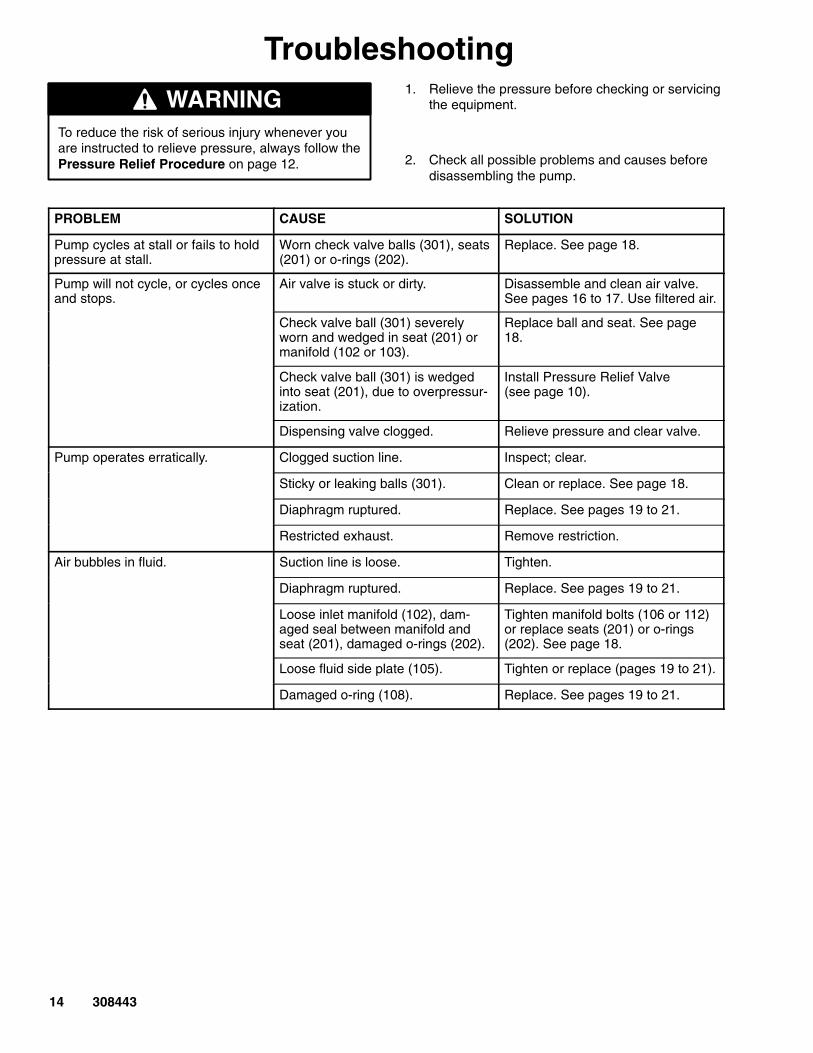
Troubleshooting
WARNINGTo reduce the risk of serious injury whenever youare instructed to relieve pressure, always follow thePressure Relief Procedure on page 12.
1. Relieve the pressure before checking or servicingthe equipment.
2. Check all possible problems and causes beforedisassembling the pump.
PROBLEM CAUSE SOLUTION
Pump cycles at stall or fails to holdpressure at stall.
Worn check valve balls (301), seats(201) or o-rings (202).
Replace. See page 18.
Pump will not cycle, or cycles onceand stops.
Air valve is stuck or dirty. Disassemble and clean air valve.See pages 16 to 17. Use filtered air.
Check valve ball (301) severelyworn and wedged in seat (201) ormanifold (102 or 103).
Replace ball and seat. See page18.
Check valve ball (301) is wedgedinto seat (201), due to overpressur-ization.
Install Pressure Relief Valve (see page 10).
Dispensing valve clogged. Relieve pressure and clear valve.
Pump operates erratically. Clogged suction line. Inspect; clear.
Sticky or leaking balls (301). Clean or replace. See page 18.
Diaphragm ruptured. Replace. See pages 19 to 21.
Restricted exhaust. Remove restriction.
Air bubbles in fluid. Suction line is loose. Tighten.
Diaphragm ruptured. Replace. See pages 19 to 21.
Loose inlet manifold (102), dam-aged seal between manifold andseat (201), damaged o-rings (202).
Tighten manifold bolts (106 or 112)or replace seats (201) or o-rings(202). See page 18.
Loose fluid side plate (105). Tighten or replace (pages 19 to 21).
Damaged o-ring (108). Replace. See pages 19 to 21.
308443 15
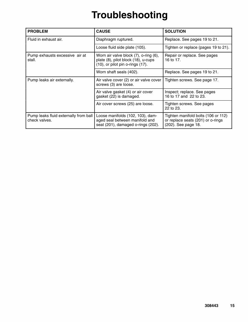
TroubleshootingPROBLEM CAUSE SOLUTION
Fluid in exhaust air. Diaphragm ruptured. Replace. See pages 19 to 21.
Loose fluid side plate (105). Tighten or replace (pages 19 to 21).
Pump exhausts excessive air atstall.
Worn air valve block (7), o-ring (6), plate (8), pilot block (18), u-cups(10), or pilot pin o-rings (17).
Repair or replace. See pages16 to 17.
Worn shaft seals (402). Replace. See pages 19 to 21.
Pump leaks air externally. Air valve cover (2) or air valve coverscrews (3) are loose.
Tighten screws. See page 17.
Air valve gasket (4) or air covergasket (22) is damaged.
Inspect; replace. See pages16 to 17 and 22 to 23.
Air cover screws (25) are loose. Tighten screws. See pages22 to 23.
Pump leaks fluid externally from ballcheck valves.
Loose manifolds (102, 103), dam-aged seal between manifold andseat (201), damaged o-rings (202).
Tighten manifold bolts (106 or 112)or replace seats (201) or o-rings(202). See page 18.

16 308443
ServiceRepairing the Air Valve
Tools Required
� Torque wrench
� Torx (T20) screwdriver or 7 mm (9/32”) socketwrench
� Needle-nose pliers
� O-ring pick
� Lithium base grease
NOTE: Air Valve Repair Kits 236273 (aluminum centerhousing models) and 255061 (sst center housingmodels) are available. Refer to page 26. Parts includedin the kit are marked with a symbol, for example (4��).Use all the parts in the kit for the best results.
Disassembly
WARNINGTo reduce the risk of serious injury whenever youare instructed to relieve pressure, always follow thePressure Relief Procedure on page 12.
1. Relieve the pressure.
2. With a Torx (T20) screwdriver or 7 mm (9/32”)socket wrench, remove the six screws (3), airvalve cover (2), and gasket (4). See Fig. 7.
3. Move the valve carriage (5) to the center positionand pull it out of the cavity. Remove the valveblock (7��) and o-ring (6��) from the carriage.Using a needle-nose pliers, pull the pilot block (18)straight up and out of the cavity. See Fig. 8.
4. Pull the two actuator pistons (11) out of the bear-ings (12). Remove the u-cup packings (10) fromthe pistons. Pull the pilot pins (16) out of thebearings (15). Remove the o-rings (17) from thepilot pins. See Fig. 9.
5. Inspect the valve plate (8) in place. If damaged,use a Torx (T20) screwdriver or 7 mm (9/32”)socket wrench to remove the three screws (3).Remove the valve plate (8) and, on aluminumcenter housing models only, remove the seal (9).See Fig. 10.
6. Inspect the bearings (12, 15) in place. See Fig. 9.The bearings are tapered and, if damaged, mustbe removed from the outside. This requires disas-sembly of the fluid section. See page 22.
7. Clean all parts and inspect for wear or damage.Replace as needed. Reassemble as explained onpage 17.
Torque to 50–60 in-lb (5.6–6.8 N-m).
Fig. 7
32
4��
2
2
04164B
04165
��18
5
Fig. 8
1
2
See Detail at right.
Grease.
3 Grease lower face.
1
��7
��6
5
2
3
3
11
16
308443 17
Service
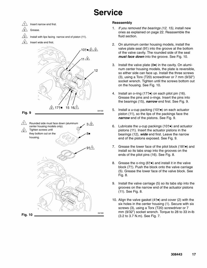
04159Fig. 9
17�� 16
11
10��
12
15
1
2
Insert narrow end first.
Grease.
3 Install with lips facing narrow end of piston (11).
4 Insert wide end first.
12
3
4
2
04160
1
28�
9�
3Rounded side must face down (aluminumcenter housing models only).Tighten screws untilthey bottom out on thehousing.
Fig. 10
1
2
Reassembly
1. If you removed the bearings (12, 15), install newones as explained on page 22. Reassemble thefluid section.
2. On aluminum center housing models, install thevalve plate seal (9�) into the groove at the bottomof the valve cavity. The rounded side of the sealmust face down into the groove. See Fig. 10.
3. Install the valve plate (8�) in the cavity. On alumi-num center housing models, the plate is reversible,so either side can face up. Install the three screws(3), using a Torx (T20) screwdriver or 7 mm (9/32”)socket wrench. Tighten until the screws bottom outon the housing. See Fig. 10.
4. Install an o-ring (17��) on each pilot pin (16).Grease the pins and o-rings. Insert the pins intothe bearings (15), narrow end first. See Fig. 9.
5. Install a u-cup packing (10��) on each actuatorpiston (11), so the lips of the packings face thenarrow end of the pistons. See Fig. 9.
6. Lubricate the u-cup packings (10��) and actuatorpistons (11). Insert the actuator pistons in thebearings (12), wide end first. Leave the narrowend of the pistons exposed. See Fig. 9.
7. Grease the lower face of the pilot block (18��) andinstall so its tabs snap into the grooves on theends of the pilot pins (16). See Fig. 8.
8. Grease the o-ring (6��) and install it in the valveblock (7�). Push the block onto the valve carriage(5). Grease the lower face of the valve block. SeeFig. 8.
9. Install the valve carriage (5) so its tabs slip into thegrooves on the narrow end of the actuator pistons(11). See Fig. 8.
10. Align the valve gasket (4��) and cover (2) with thesix holes in the center housing (1). Secure with sixscrews (3), using a Torx (T20) screwdriver or 7mm (9/32”) socket wrench. Torque to 28 to 33 in-lb(3.2 to 3.7 N.m). See Fig. 7.

18 308443
ServiceBall Check Valve Repair
Tools Required
� Torque wrench
� 10 mm socket wrench
� O-ring pick
Disassembly
NOTE: A Fluid Section Repair Kit is available. Refer topage 25 to order the correct kit for your pump. Partsincluded in the kit are marked with an asterisk, forexample (201*). Use all the parts in the kit for the bestresults.
NOTE: To ensure proper seating of the balls (301),always replace the seats (201) when replacing theballs.
WARNINGTo reduce the risk of serious injury whenever youare instructed to relieve pressure, always follow thePressure Relief Procedure on page 12.
1. Relieve the pressure. Disconnect all hoses.
2. Remove the pump from its mounting.
3. Using a 10 mm socket wrench, remove the fourbolts (106) holding the outlet manifold (103) to thefluid covers (101). See Fig. 11.
4. Remove the seats (201), balls (301), and o-rings(202) from the manifold.
NOTE: Some models use two o-rings (202), somemodels use four o-rings (202), and some models donot use o-rings.
5. Turn the pump over and remove the inlet manifold(102). Remove the seats (201), balls (301), ando-rings (202) from the fluid covers (101).
Reassembly
1. Clean all parts and inspect for wear or damage.Replace parts as needed.
2. Reassemble in the reverse order, following allnotes in Fig. 11. Assemble the ball checks exactlyas shown. The arrows (A) on the fluid covers (101)must point toward the outlet manifold (103).
Fig. 11
1
2
Torque to 80 to 90 in-lb (9 to 10 N-m). See Torque Se-quence, page 30.
Arrow (A) must point toward outlet manifold (103).
106
103
101
A
201*301*
112
102
201*
301*
2
1
1
202*
202*
3 Not used on some models.
3
3
4 Beveled seating surface must face ball (301).
4
4
04157B

308443 19
ServiceDiaphragm Repair
Tools Required
� Torque wrench
� 10 mm socket wrench
� 19 mm open–end wrench
� Adjustable wrench
� O-ring pick
� Lithium-base grease
DisassemblyNOTE: A Fluid Section Repair Kit is available. Refer topage 25 to order the correct kit for your pump. Partsincluded in the kit are marked with an asterisk, forexample (401*). Use all the parts in the kit for the bestresults.
WARNINGTo reduce the risk of serious injury whenever youare instructed to relieve pressure, always follow thePressure Relief Procedure on page 12.
1. Relieve the pressure.
2. Remove the manifolds and disassemble the ballcheck valves as explained on page 18.
3. Using a 10 mm socket wrench, remove the screws(106 and 112) holding the fluid covers (101) to theair covers (23). Pull the fluid covers (101) off thepump. See Fig. 12.
Fig. 12
1
2
23
101
A 2
B
Arrow (A) must point toward air valve (B).
You must torque the eight long screws (106) first, then the shortscrews (112). Torque to 130 to 150 in-lb (14 to 17 N�m). SeeTorque Sequence, page 30.
1 112 106 1
113
04162B

20 308443
Service4. Unscrew one outer plate (105) from the diaphragm
shaft (24). Remove one diaphragm (401), and theinner plate (104). See Fig. 13.
For overmolded diaphragms: Grip both dia-phragms securely around the outer edge androtate counterclockwise. One diaphragm assemblywill come free and the other will remain attached tothe shaft. Remove the freed diaphragm and airside plate.
NOTE: PTFE models include a PTFE diaphragm (403)in addition to the backup diaphragm (401).
5. Pull the other diaphragm assembly and the dia-phragm shaft (24) out of the center housing (1).Hold the shaft flats with a 19 mm open–endwrench, and remove the outer plate (105) from theshaft. Disassemble the remaining diaphragmassembly.
For overmolded diaphragms: Pull the other dia-phragm assembly and the diaphragm shaft (24)out of the center housing (1). Hold the shaft flatswith a 19 mm open–end wrench and remove thediaphragm and air side plate from the shaft.
6. Inspect the diaphragm shaft (24) for wear orscratches. If it is damaged, inspect the bearings(19) in place. If the bearings are damaged, refer topage 22.
7. Reach into the center housing (1) with an o-ringpick and hook the u-cup packings (402), then pullthem out of the housing. This can be done with thebearings (19) in place.
8. Clean all parts and inspect for wear or damage.Replace parts as needed.
Reassembly1. Grease the shaft u-cup packings (402*) and install
them so the lips face out of the housing (1). SeeFig. 13.
2. Grease the length and ends of the diaphragm shaft(24), and slide it through the housing (1).
3. Assemble the inner diaphragm plates (104), dia-phragms (401*), PTFE diaphragms (403*, if pres-ent), and outer diaphragm plates (105) exactly asshown in Fig. 13. These parts must be assembledcorrectly.
For overmolded diaphragms: Assemble the airside plate (104) onto the diaphragm (403). Thewide, radiused side of the plate must face thediaphragm. Apply medium–strength (blue) Loctiteor equivalent to the threads of the diaphragmassembly. Screw the assembly into the shaft (24)hand tight. NOTE: Step 4 does not apply to pumpswith overmolded diaphragms; go to step 5.
4. Apply medium-strength (blue) Loctite� or equiva-lent to the threads of the fluid-side plates (105).Hold one of the outer plates (105) with a wrench,and torque the other outer plate to 20 to 25 ft-lb(27 to 34 N-m) at 100 rpm maximum. Do notover-torque.
5. Align the fluid covers (101) and the center housing(1) so the arrows (A) on the covers face the samedirection as the air valve (B). Secure the coverswith the screws (106 and 112), handtight. Placethe bolt caps (113*) on the longer screws (106),and install the longer screws in the top and bottomholes of the covers. See Fig. 12.
6. First, torque the longer screws (106) oppositelyand evenly to 130 to 150 in-lb (14 to 17 N�m),using a 10 mm socket wrench. Then torque theshorter screws (112). See Torque Sequence,page 30.
7. Reassemble the ball check valves and manifoldsas explained on page 18.

308443 21
Service
04236 02637
Fig. 13
1
3
4
2
24
104
403*
401*
24
24 104 401* 403*
105
19 402*
Cutaway View, with Diaphragms in Place Cutaway View, with Diaphragms Removed
1
Lips face out of housing (1).
Rounded side faces diaphragm (401).
Air Side must face center housing (1).
1
Grease.
Apply medium-strength (blue) Loctite� or equiva-lent. Torque to 20 to 25 ft-lb (27 to 34 N-m) at 100rpm maximum.
Used on Models with PTFE diaphragms only.
5
6
1
33
3
3
1
4
4
4
5
6
6
105
2
2
5
04161B
22 308443
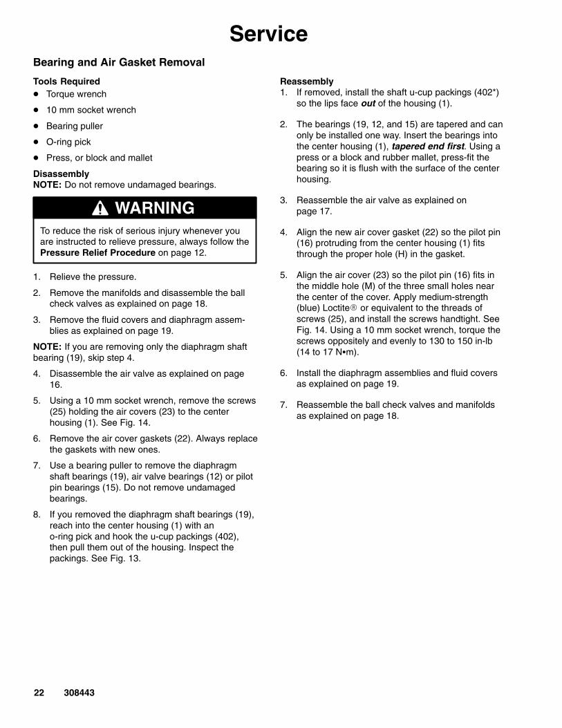
ServiceBearing and Air Gasket Removal
Tools Required� Torque wrench
� 10 mm socket wrench
� Bearing puller
� O-ring pick
� Press, or block and mallet
DisassemblyNOTE: Do not remove undamaged bearings.
WARNINGTo reduce the risk of serious injury whenever youare instructed to relieve pressure, always follow thePressure Relief Procedure on page 12.
1. Relieve the pressure.
2. Remove the manifolds and disassemble the ballcheck valves as explained on page 18.
3. Remove the fluid covers and diaphragm assem-blies as explained on page 19.
NOTE: If you are removing only the diaphragm shaftbearing (19), skip step 4.
4. Disassemble the air valve as explained on page16.
5. Using a 10 mm socket wrench, remove the screws(25) holding the air covers (23) to the centerhousing (1). See Fig. 14.
6. Remove the air cover gaskets (22). Always replacethe gaskets with new ones.
7. Use a bearing puller to remove the diaphragmshaft bearings (19), air valve bearings (12) or pilotpin bearings (15). Do not remove undamagedbearings.
8. If you removed the diaphragm shaft bearings (19),reach into the center housing (1) with an o-ring pick and hook the u-cup packings (402),then pull them out of the housing. Inspect thepackings. See Fig. 13.
Reassembly1. If removed, install the shaft u-cup packings (402*)
so the lips face out of the housing (1).
2. The bearings (19, 12, and 15) are tapered and canonly be installed one way. Insert the bearings intothe center housing (1), tapered end first. Using apress or a block and rubber mallet, press-fit thebearing so it is flush with the surface of the centerhousing.
3. Reassemble the air valve as explained onpage 17.
4. Align the new air cover gasket (22) so the pilot pin(16) protruding from the center housing (1) fitsthrough the proper hole (H) in the gasket.
5. Align the air cover (23) so the pilot pin (16) fits inthe middle hole (M) of the three small holes nearthe center of the cover. Apply medium-strength(blue) Loctite� or equivalent to the threads ofscrews (25), and install the screws handtight. SeeFig. 14. Using a 10 mm socket wrench, torque thescrews oppositely and evenly to 130 to 150 in-lb(14 to 17 N�m).
6. Install the diaphragm assemblies and fluid coversas explained on page 19.
7. Reassemble the ball check valves and manifoldsas explained on page 18.

308443 23
Service
02639B
04158
Fig. 14
1
3
2
25
2322
1
19
15
12
16
HM
Insert bearings tapered end first.
Press-fit bearings flush with surface of center housing (1).
Apply medium-strength (blue) Loctite� or equivalent.Torque to 130 to 150 in-lb (14 to 17 N�m).
Detail of Air Valve Bearings
1
1
1
2
2
2
3
1
24 308443
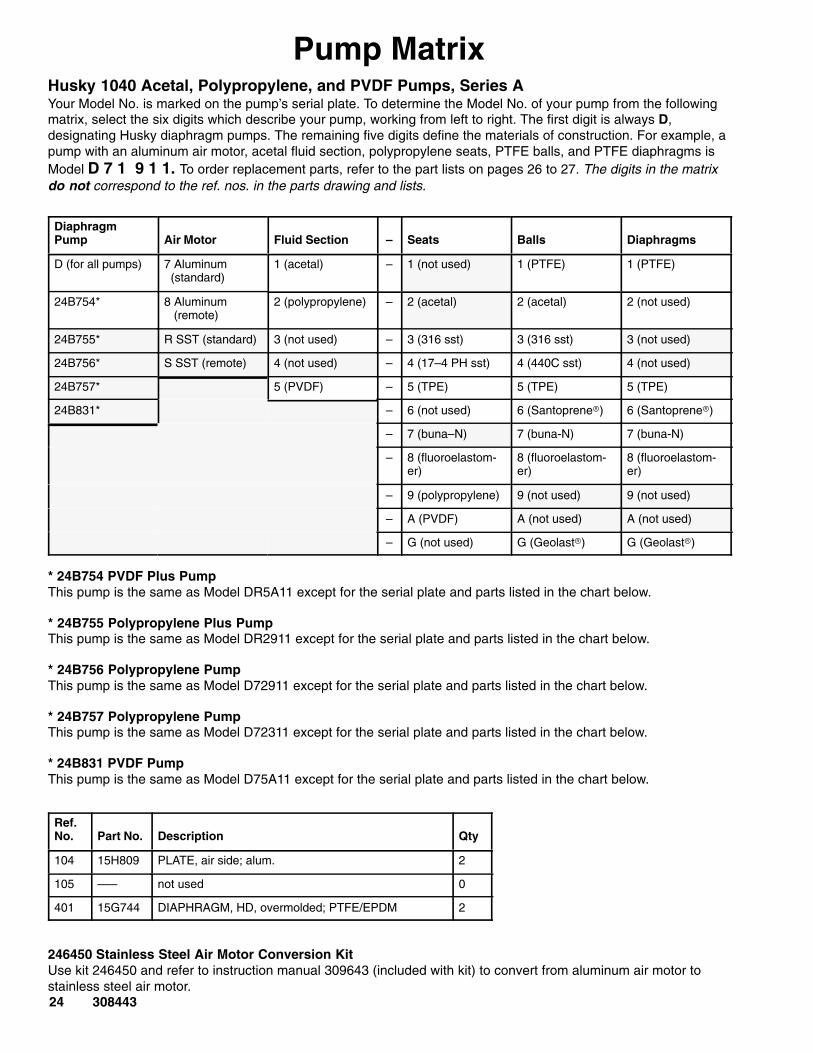
Pump MatrixHusky 1040 Acetal, Polypropylene, and PVDF Pumps, Series AYour Model No. is marked on the pump’s serial plate. To determine the Model No. of your pump from the followingmatrix, select the six digits which describe your pump, working from left to right. The first digit is always D,designating Husky diaphragm pumps. The remaining five digits define the materials of construction. For example, apump with an aluminum air motor, acetal fluid section, polypropylene seats, PTFE balls, and PTFE diaphragms isModel D 7 1 9 1 1. To order replacement parts, refer to the part lists on pages 26 to 27. The digits in the matrixdo not correspond to the ref. nos. in the parts drawing and lists.
DiaphragmPump Air Motor Fluid Section – Seats Balls Diaphragms
D (for all pumps) 7 Aluminum (standard)
1 (acetal) – 1 (not used) 1 (PTFE) 1 (PTFE)
24B754* 8 Aluminum (remote)
2 (polypropylene) – 2 (acetal) 2 (acetal) 2 (not used)
24B755* R SST (standard) 3 (not used) – 3 (316 sst) 3 (316 sst) 3 (not used)
24B756* S SST (remote) 4 (not used) – 4 (17–4 PH sst) 4 (440C sst) 4 (not used)
24B757* 5 (PVDF) – 5 (TPE) 5 (TPE) 5 (TPE)
24B831* – 6 (not used) 6 (Santoprene) 6 (Santoprene)
– 7 (buna–N) 7 (buna-N) 7 (buna-N)
– 8 (fluoroelastom-er)
8 (fluoroelastom-er)
8 (fluoroelastom-er)
– 9 (polypropylene) 9 (not used) 9 (not used)
– A (PVDF) A (not used) A (not used)
– G (not used) G (Geolast) G (Geolast)
* 24B754 PVDF Plus PumpThis pump is the same as Model DR5A11 except for the serial plate and parts listed in the chart below.
* 24B755 Polypropylene Plus PumpThis pump is the same as Model DR2911 except for the serial plate and parts listed in the chart below.
* 24B756 Polypropylene PumpThis pump is the same as Model D72911 except for the serial plate and parts listed in the chart below.
* 24B757 Polypropylene PumpThis pump is the same as Model D72311 except for the serial plate and parts listed in the chart below.
* 24B831 PVDF PumpThis pump is the same as Model D75A11 except for the serial plate and parts listed in the chart below.
Ref.No. Part No. Description Qty
104 15H809 PLATE, air side; alum. 2
105 ––– not used 0
401 15G744 DIAPHRAGM, HD, overmolded; PTFE/EPDM 2
246450 Stainless Steel Air Motor Conversion KitUse kit 246450 and refer to instruction manual 309643 (included with kit) to convert from aluminum air motor tostainless steel air motor.
308443 25
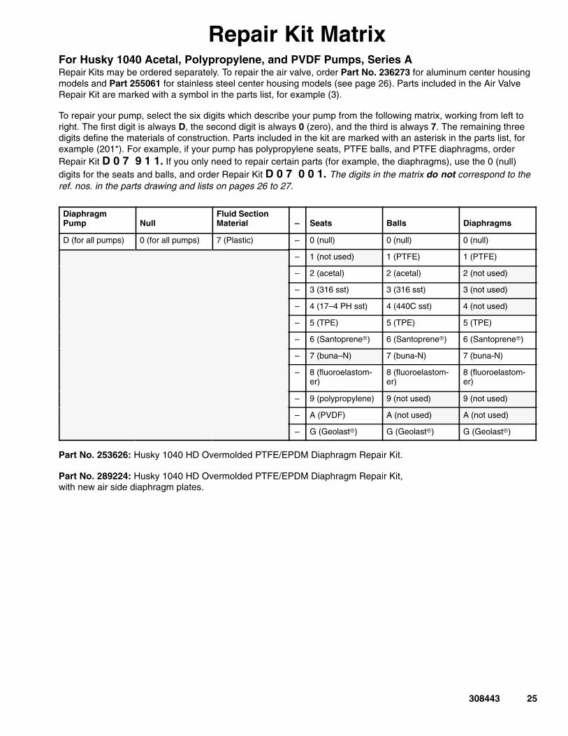
Repair Kit MatrixFor Husky 1040 Acetal, Polypropylene, and PVDF Pumps, Series ARepair Kits may be ordered separately. To repair the air valve, order Part No. 236273 for aluminum center housingmodels and Part 255061 for stainless steel center housing models (see page 26). Parts included in the Air ValveRepair Kit are marked with a symbol in the parts list, for example (3).
To repair your pump, select the six digits which describe your pump from the following matrix, working from left toright. The first digit is always D, the second digit is always 0 (zero), and the third is always 7. The remaining threedigits define the materials of construction. Parts included in the kit are marked with an asterisk in the parts list, forexample (201*). For example, if your pump has polypropylene seats, PTFE balls, and PTFE diaphragms, orderRepair Kit D 0 7 9 1 1. If you only need to repair certain parts (for example, the diaphragms), use the 0 (null)digits for the seats and balls, and order Repair Kit D 0 7 0 0 1. The digits in the matrix do not correspond to theref. nos. in the parts drawing and lists on pages 26 to 27.
DiaphragmPump Null
Fluid SectionMaterial – Seats Balls Diaphragms
D (for all pumps) 0 (for all pumps) 7 (Plastic) – 0 (null) 0 (null) 0 (null)
– 1 (not used) 1 (PTFE) 1 (PTFE)
– 2 (acetal) 2 (acetal) 2 (not used)
– 3 (316 sst) 3 (316 sst) 3 (not used)
– 4 (17–4 PH sst) 4 (440C sst) 4 (not used)
– 5 (TPE) 5 (TPE) 5 (TPE)
– 6 (Santoprene) 6 (Santoprene) 6 (Santoprene)
– 7 (buna–N) 7 (buna-N) 7 (buna-N)
– 8 (fluoroelastom-er)
8 (fluoroelastom-er)
8 (fluoroelastom-er)
– 9 (polypropylene) 9 (not used) 9 (not used)
– A (PVDF) A (not used) A (not used)
– G (Geolast) G (Geolast) G (Geolast)
Part No. 253626: Husky 1040 HD Overmolded PTFE/EPDM Diaphragm Repair Kit.
Part No. 289224: Husky 1040 HD Overmolded PTFE/EPDM Diaphragm Repair Kit,with new air side diaphragm plates.
26 308443
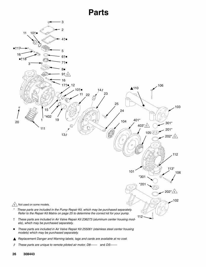
Parts
1 Not used on some models.
* These parts are included in the Pump Repair Kit, which may be purchased separately.Refer to the Repair Kit Matrix on page 25 to determine the correct kit for your pump.
� These parts are included in Air Valve Repair Kit 236273 (aluminum center housing mod-els), which may be purchased separately.
� These parts are included in Air Valve Repair Kit 255061 (stainless steel center housingmodels) which may be purchased separately.
Replacement Danger and Warning labels, tags and cards are available at no cost.
� These parts are unique to remote piloted air motor, D8–––– and DS––––
13�
1
2
3
4��
5
6��
7��
8�9�
10��11
12
15
1617��
��18
1920
22 23
24
25
101
102
103
104
105
110
111
106
201*
202*
301*401*
*402
403*
3
16
��17
11 10��
112
112
*201
*301
1
1
202* 1
106
113*
14�
1
308443 27
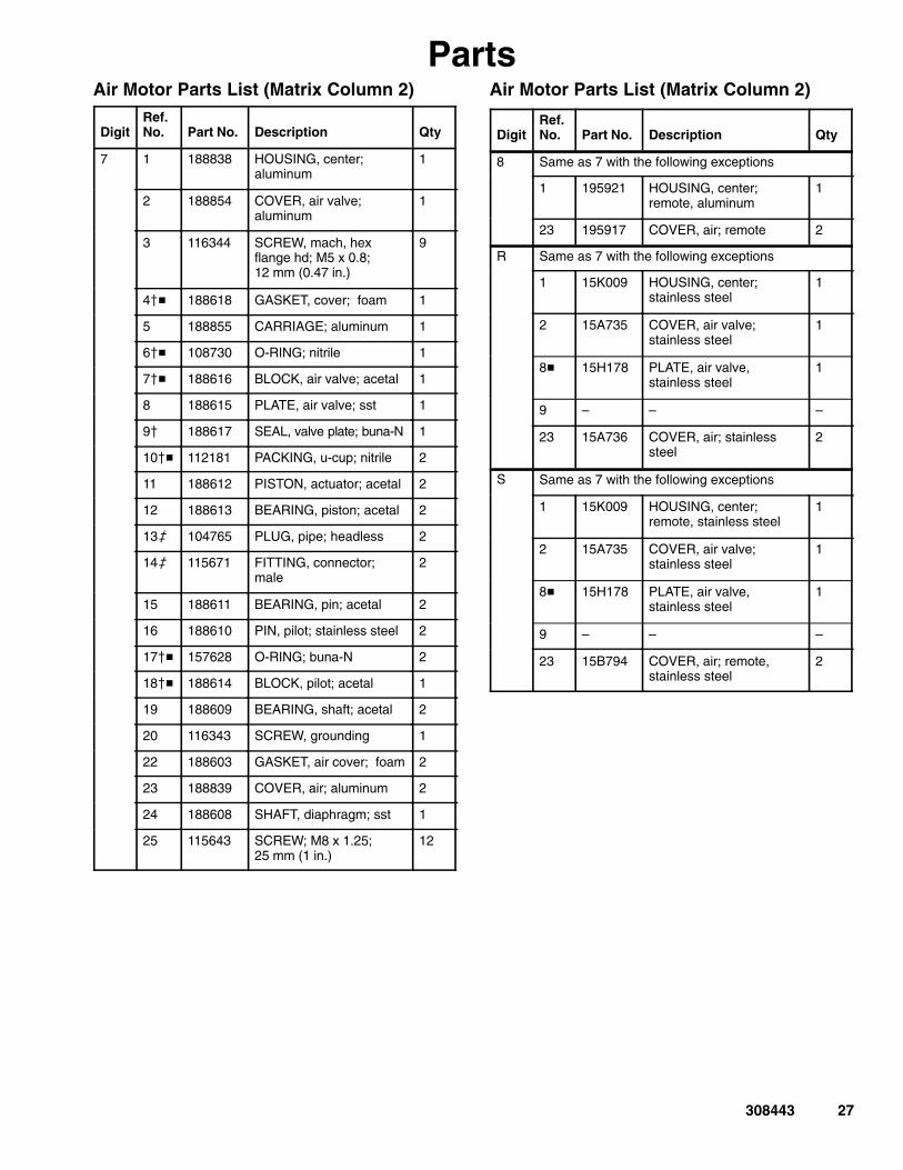
PartsAir Motor Parts List (Matrix Column 2)
DigitRef.No. Part No. Description Qty
7 1 188838 HOUSING, center; aluminum
1
2 188854 COVER, air valve; aluminum
1
3 116344 SCREW, mach, hexflange hd; M5 x 0.8; 12 mm (0.47 in.)
9
4�� 188618 GASKET, cover; foam 1
5 188855 CARRIAGE; aluminum 1
6�� 108730 O-RING; nitrile 1
7�� 188616 BLOCK, air valve; acetal 1
8 188615 PLATE, air valve; sst 1
9� 188617 SEAL, valve plate; buna-N 1
10�� 112181 PACKING, u-cup; nitrile 2
11 188612 PISTON, actuator; acetal 2
12 188613 BEARING, piston; acetal 2
13� 104765 PLUG, pipe; headless 2
14� 115671 FITTING, connector;male
2
15 188611 BEARING, pin; acetal 2
16 188610 PIN, pilot; stainless steel 2
17�� 157628 O-RING; buna-N 2
18�� 188614 BLOCK, pilot; acetal 1
19 188609 BEARING, shaft; acetal 2
20 116343 SCREW, grounding 1
22 188603 GASKET, air cover; foam 2
23 188839 COVER, air; aluminum 2
24 188608 SHAFT, diaphragm; sst 1
25 115643 SCREW; M8 x 1.25; 25 mm (1 in.)
12
Air Motor Parts List (Matrix Column 2)
DigitRef.No. Part No. Description Qty
8 Same as 7 with the following exceptions
1 195921 HOUSING, center; remote, aluminum
1
23 195917 COVER, air; remote 2
R Same as 7 with the following exceptions
1 15K009 HOUSING, center; stainless steel
1
2 15A735 COVER, air valve; stainless steel
1
8� 15H178 PLATE, air valve, stainless steel
1
9 – – –
23 15A736 COVER, air; stainlesssteel
2
S Same as 7 with the following exceptions
1 15K009 HOUSING, center; remote, stainless steel
1
2 15A735 COVER, air valve; stainless steel
1
8� 15H178 PLATE, air valve, stainless steel
1
9 – – –
23 15B794 COVER, air; remote,stainless steel
2
28 308443
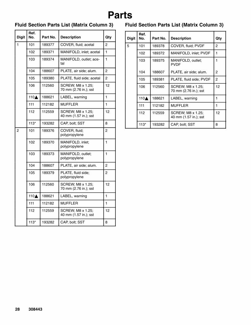
PartsFluid Section Parts List (Matrix Column 3)
DigitRef.No. Part No. Description Qty
1 101 189377 COVER, fluid; acetal 2
102 189371 MANIFOLD, inlet; acetal 1
103 189374 MANIFOLD, outlet; ace-tal
1
104 188607 PLATE, air side; alum. 2
105 189380 PLATE, fluid side; acetal 2
106 112560 SCREW; M8 x 1.25; 70 mm (2.76 in.); sst
12
110 188621 LABEL, warning 1
111 112182 MUFFLER 1
112 112559 SCREW; M8 x 1.25; 40 mm (1.57 in.); sst
12
113* 193282 CAP, bolt; SST 8
2 101 189376 COVER, fluid; polypropylene
2
102 189370 MANIFOLD, inlet; polypropylene
1
103 189373 MANIFOLD, outlet; polypropylene
1
104 188607 PLATE, air side; alum. 2
105 189379 PLATE, fluid side; polypropylene
2
106 112560 SCREW; M8 x 1.25; 70 mm (2.76 in.); sst
12
110 188621 LABEL, warning 1
111 112182 MUFFLER 1
112 112559 SCREW; M8 x 1.25; 40 mm (1.57 in.); sst
12
113* 193282 CAP, bolt; SST 8
Fluid Section Parts List (Matrix Column 3)
DigitRef.No. Part No. Description Qty
5 101 189378 COVER, fluid; PVDF 2
102 189372 MANIFOLD, inlet; PVDF 1
103 189375 MANIFOLD, outlet;PVDF
1
104 188607 PLATE, air side; alum. 2
105 189381 PLATE, fluid side; PVDF 2
106 112560 SCREW; M8 x 1.25; 70 mm (2.76 in.); sst
12
110 188621 LABEL, warning 1
111 112182 MUFFLER 1
112 112559 SCREW; M8 x 1.25; 40 mm (1.57 in.); sst
12
113* 193282 CAP, bolt; SST 8

308443 29
PartsSeat Parts List (Matrix Column 4)
DigitRef.No. Part No. Description Qty
2 201* 188604 SEAT; acetal 4
202* 109205 O-RING; PTFE 8
3 201* 188707 SEAT; 316 stainless steel 4
202* 109205 O-RING; PTFE 8
4 201* 188708 SEAT; 17-4 stainless steel 4
202* 109205 O-RING; PTFE 8
5 201* 188711 SEAT; TPE 4
202 None Not Used 0
6 201* 191595 SEAT; Santoprene� 4
202* 114229 O-RING; PTFE encapsu-lated
8
7 201* 15B275 SEAT; Buna–N 4
202 None Not used 0
8 201* 15B633 SEAT; fluoroelastomer 4
202 None Not Used 0
9 201* 189722 SEAT; polypropylene 4
202* 109205 O-RING; PTFE 8
A 201* 189723 SEAT; PVDF 4
202* 109205 O-RING; PTFE 8
G 201* 194211 SEAT; Geolast� 4
202* 109205 O-RING; PTFE 8
Ball Parts List (Matrix Column 5)
DigitRef.No. Part No. Description Qty
1 301* 112088 BALL; PTFE 4
2 301* 112254 BALL; acetal 4
3 301* 103869 BALL; 316 stainless steel 4
4 301* 102973 BALL; 440C stainlesssteel
4
5 301* 112089 BALL; TPE 4
6 301* 112092 BALL; Santoprene� 4
7 301* 15B488 BALL; buna-N 4
8 301* 15B487 BALL; fluoroelastomer 4
G 301* 114751 BALL; Geolast� 4
Diaphragm Parts List (Matrix Column 6)
DigitRef.No. Part No. Description Qty
1 401* Not soldseparately
DIAPHRAGM, backup;polychloropene (CR)
2
402* 112181 PACKING, u-cup; nitrile 2
403* 188605 DIAPHRAGM; PTFE 2
5 401* 188606 DIAPHRAGM; TPE 2
402* 112181 PACKING, u-cup; nitrile 2
6 401* 188857 DIAPHRAGM;Santoprene�
2
402* 112181 PACKING, u-cup; nitrile 2
7 401* 15B499 DIAPHRAGM; buna-N 2
402* 112181 PACKING, u-cup; nitrile 2
8 401* 15B500 DIAPHRAGM; fluoroelas-tomer
2
402* 112181 PACKING, u-cup; nitrile 2
G 401* 194212 DIAPHRAGM; Geolast� 2
402* 112181 PACKING, u-cup; nitrile 2
* These parts are included in the pump repair kit, purchasedseparately. See Repair Kit Matrix on page 25 to determinethe correct kit for your pump.

30 308443
Torque SequenceAlways follow torque sequence when instructed to torque fasteners.
1. Left/Right Fluid CoversTorque bolts to 130–150 in–lb (14–17 N�m)
4 2
7
5
3
6
8
1
2. Inlet ManifoldTorque bolts to 80–90 in–lb (9–10 N�m)
9 12
11 10
3. Outlet ManifoldTorque bolts to 80–90 in–lb (9–10 N�m)13 16
15 14
308443 31
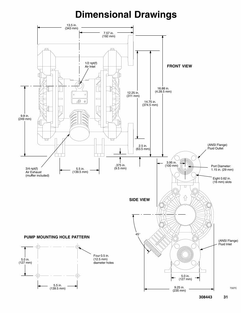
Dimensional Drawings
SIDE VIEW
(ANSI Flange)Fluid Outlet
Port Diameter:1.15 in. (29 mm)
Eight 0.62 in.(16 mm) slots
5.0 in.(127 mm)
9.25 in.(235 mm)
3.95 in.(100 mm)
45�
(ANSI Flange)Fluid Inlet
FRONT VIEW
3/4 npt(f)Air Exhaust(muffler included)
1/2 npt(f)Air Inlet
12.25 in.(311 mm)
16.88 in.(4.28.5 mm)
5.5 in.(139.5 mm)
2.5 in.(63.5 mm)
14.75 in.(374.5 mm)
9.8 in.(249 mm)
7.57 in.(192 mm)
.375 in.(9.5 mm)
13.5 in.(343 mm)
7337C
PUMP MOUNTING HOLE PATTERN
Four 0.5 in.(12.5 mm) diameter holes
5.0 in.(127 mm)
5.5 in.(139.5 mm)

32 308443
Technical DataMaximum fluid working pressure 120 psi . . . . . . . . . . . . . . . . .
(0.8 MPa, 8 bar)Air pressure operating range 20 to 120 psi. . . . . . . . . . . . . . . .
(0.14 to 0.8 MPa, 1.4 to 8 bar)Maximum air consumption 60 scfm. . . . . . . . . . . . . . . . . . . . . . Air consumption at 70 psi/20 gpm 20 scfm (see chart). . . . . Maximum free-flow delivery 42 gpm (159 l/min). . . . . . . . . . . . Maximum pump speed 276 cpm. . . . . . . . . . . . . . . . . . . . . . . . . Gallons (Liters) per cycle 0.15 (0.57). . . . . . . . . . . . . . . . . . . . . Maximum suction lift 18 ft (5.48 m) wet or dry. . . . . . . . . . . . . Maximum Size pumpable solids 1/8 in. (3.2 mm). . . . . . . . . . . * Maximum noise level at 100 psi, 50 cpm 89 dBa. . . . . . . .
Sound power level 100 dBa. . . . . . . . . . . . . . . . . . . . . . . . . . * Noise level at 70 psi, 50 cycles/min: 78 dBa. . . . . . . . . . . . Maximum operating temperature 150�F (65.5�C). . . . . . . . . . . Air inlet size 1/2 npt(f). . . . . . . . . . . . . . . . . . . . . . . . . . . . . . . . . . Fluid inlet size. 1” Raised Face Flange. . . . . . . . . . . . . . . . . . . Fluid outlet size. 1” Raised Face Flange. . . . . . . . . . . . . . . . . .
Wetted parts Vary by Model. See pages 27 and 29. . . . . . . . . Non-wetted external parts aluminum, 302, 316 stainless steel
polyester (labels)Weight (approximate) Polypropylene Models . . . . . . . . . . . . .
with aluminum center section: 19 lb (8.6 kg). . . . . . . . . . . . . . . with stainless steel center section : 32 lb (14.6 kg). . . . . . . . . .
Acetal Models . . . . . . . . . . . . . . . . . . . . . . . . . . . . . . . . . . . . . . . . with aluminum center section : 22 lb (10 kg). . . . . . . . . . . . . . .
PVDF Models . . . . . . . . . . . . . . . . . . . . . . . . . . . . . . . . . . . . . . . . with aluminum center section: 25 lb (11.3 kg). . . . . . . . . . . . . .
with stainless steel center section: 35 lb (16 kg). . . . . . . . . . . .
Geolast and Santoprene are registered trademarks of theMonsanto Co.
Loctite is a registered trademark of the Loctite Corporation.* Noise levels measured with the pump mounted on the floor,
using Rubber Foot Kit 236452. Sound power measured perISO Standard 9216.

308443 33
Performance ChartTest Conditions: Pump tested in water with inlet submerged.
0
20
40
60
80
100
120
0 5 10 15 20 25 30 35 40
(0.7, 7)
Fluid Pressure Curves
A at 120 psi (0.7 MPa, 7 bar) air pressure
B at 100 psi (0.7 MPa, 7 bar) air pressure
C at 70 psi (0.48 MPa, 4.8 bar) air pressure
D at 40 psi (0.28 MPa, 2.8 bar) air pressure
A
B
D
To find Fluid Outlet Pressure(psi/MPa/bar) at a specific fluid flow(gpm/lpm) and operating air pressure(psi/MPa/bar):
1. Locate fluid flow rate along bottom ofchart.
2. Follow vertical line up to intersectionwith selected fluid outlet pressure curve.
3. Follow left to scale to read fluid outletpressure. F
LU
ID O
UT
LE
T P
RE
SS
UR
E––
psi
(M
Pa,
bar
)
(0.55, 5.5)
(0.41, 4.1)
(0.28, 2.8)
(0.14, 1.4)
C
(0.84, 8.4)
FLUID FLOW--gpm (lpm)
(38) (133) (152)(76) (114)(95)(57)(19)
0
10
20
30
40
50
60
0 5 10 15 20 25 30 35 40
FLUID FLOW--gpm (lpm)
AIR
CO
NS
UM
PT
ION
––sc
fm (
cub
ic m
eter
s/m
in)
To find Pump Air Consumption (scfm orm�/min) at a specific fluid flow (gpm/lpm) andair pressure (psi/MPa/bar):
1. Locate fluid flow rate along bottom of chart.
2. Read vertical line up to intersection withselected air consumption curve.
3. Follow left to scale to read air consumption.
(38) (133)
(1.68)
(152)(76) (114)
(1.40)
(1.12)
(0.84)
(0.56)
Air Consumption Curves
A at 120 psi (0.7 MPa, 7 bar) air pressure
B at 100 psi (0.7 MPa, 7 bar) air pressure
C at 70 psi (0.48 MPa, 4.8 bar) air pressure
D at 40 psi (0.28 MPa, 2.8 bar) air pressure
B
C
A
D
(0.28)
(95)(57)(19)
34 308443
Graco WarrantiesGraco Standard Husky Pump WarrantyGraco warrants all equipment manufactured by Graco and bearing its name to be free from defects in material and workmanship on thedate of sale to the original purchaser for use. With the exception of any special, extended, or limited warranty published by Graco,Graco will, for a period of five years from the date of sale, repair or replace any part of the equipment determined by Graco to bedefective. This warranty applies only when the equipment is installed, operated and maintained in accordance with Graco’s writtenrecommendations.
This warranty does not cover, and Graco shall not be liable for general wear and tear, or any malfunction, damage or wear caused byfaulty installation, misapplication, abrasion, corrosion, inadequate or improper maintenance, negligence, accident, tampering, or sub-stitution of non-Graco component parts. Nor shall Graco be liable for malfunction, damage or wear caused by the incompatibility ofGraco equipment with structures, accessories, equipment or materials not supplied by Graco, or the improper design, manufacture,installation, operation or maintenance of structures, accessories, equipment or materials not supplied by Graco.
This warranty is conditioned upon the prepaid return of the equipment claimed to be defective to an authorized Graco distributor forverification of the claimed defect. If the claimed defect is verified, Graco will repair or replace free of charge any defective parts. Theequipment will be returned to the original purchaser transportation prepaid. If inspection of the equipment does not disclose any defectin material or workmanship, repairs will be made at a reasonable charge, which charges may include the costs of parts, labor, andtransportation.
THIS WARRANTY IS EXCLUSIVE, AND IS IN LIEU OF ANY OTHER WARRANTIES, EXPRESS OR IMPLIED, INCLUDING BUTNOT LIMITED TO WARRANTY OF MERCHANTABILITY OR WARRANTY OF FITNESS FOR A PARTICULAR PURPOSE.
Graco’s sole obligation and buyer’s sole remedy for any breach of warranty shall be as set forth above. The buyer agrees that no otherremedy (including, but not limited to, incidental or consequential damages for lost profits, lost sales, injury to person or property, or anyother incidental or consequential loss) shall be available. Any action for breach of warranty must be brought within six years of the dateof sale.
Graco makes no warranty, and disclaims all implied warranties of merchantability and fitness for a particular purpose in connectionwith accessories, equipment, materials or components sold but not manufactured by Graco. These items sold, but not manufacturedby Graco (such as electric motors, switches, hose, etc.), are subject to the warranty, if any, of their manufacturer. Graco will providepurchaser with reasonable assistance in making any claim for breach of these warranties.
In no event will Graco be liable for indirect, incidental, special or consequential damages resulting from Graco supplying equipmenthereunder, or the furnishing, performance, or use of any products or other goods sold hereto, whether due to a breach of contract,breach of warranty, the negligence of Graco, or otherwise.
FOR GRACO CANADA CUSTOMERSThe parties acknowledge that they have required that the present document, as well as all documents, notices and legal proceedingsentered into, given or instituted pursuant hereto or relating directly or indirectly hereto, be drawn up in English. Les parties reconnais-sent avoir convenu que la rédaction du présente document sera en Anglais, ainsi que tous documents, avis et procédures judiciairesexécutés, donnés ou intentés à la suite de ou en rapport, directement ou indirectement, avec les procedures concernées.
Extended Product WarrantyGraco warrants all Husky 205, 307, 515, 716, 1040, 1590, 2150, and 3275 air valve center sections to be free from defects in materialand workmanship for a period of fifteen years from date installed in service by the original purchaser. Normal wear of items such aspackings or seals are not considered to be defects in material and workmanship.
Five years Graco will provide parts and labor.Six to Fifteen years Graco will replace defective parts only.
Graco InformationFor the latest information about Graco products, visit www.graco.com.
TO PLACE AN ORDER, contact your Graco distributor, or call to identify the nearest distributor.1–800–328–0211 Toll Free, 612–623–6921, 612–378–3505 Fax
All written and visual data contained in this document reflects the latest product information available at the time of publication.Graco reserves the right to make changes at any time without notice.
This manual contains English. MM 308443
Graco Headquarters: MinneapolisInternational Offices: Belgium, China, Japan, Korea
������������ �������������������������������
��������� ��������������������������������� ���
www.graco.comRevised 04/2009


