acetal and polypropylene husky 307 …€¦ · acetal and polypropylene husky™ 307 air–operated...
TRANSCRIPT

ACETAL AND POLYPROPYLENE
Husky™ 307 Air–OperatedDiaphragm PumpsFor fluid transfer applications. For professional use only.
Only pumps with acetal fluid sections are approved for use in Europeanexplosive atmosphere locations.
100 psi (0.7 MPa, 7 bar) Maximum Fluid Working Pressure100 psi (0.7 MPa, 7 bar) Maximum Air Input Pressure
*Model No. D31 Acetal Pumps**, Series F*Model No. D32 Polypropylene Pumps, Series F*Model No. D3A Acetal BSPT Pumps**, Series F*Model No. D3B Polypropylene BSPT Pumps, Series F* To determine the Model No. for your pump and for additional models, refer to the Pump Matrix
on page 26.
** Pumps with Acetal fluid sections are certified.
Instructions–Parts List
308553ZAD��
Important Safety InstructionsRead all warnings and instructions in this manual.Save these instructions.
01428B

2 308553
Table of ContentsWarnings 2. . . . . . . . . . . . . . . . . . . . . . . . . . . . . . . . . . . . . . Installation 4. . . . . . . . . . . . . . . . . . . . . . . . . . . . . . . . . . . . . Operation 11. . . . . . . . . . . . . . . . . . . . . . . . . . . . . . . . . . . . Troubleshooting 12. . . . . . . . . . . . . . . . . . . . . . . . . . . . . . . Maintenance 14. . . . . . . . . . . . . . . . . . . . . . . . . . . . . . . . . . Service
Replacing the Air Valve 16. . . . . . . . . . . . . . . . . . . . . . Repairing the Air Valve 18. . . . . . . . . . . . . . . . . . . . . . Ball Check Valves 21. . . . . . . . . . . . . . . . . . . . . . . . . . Diaphragm Repair 23. . . . . . . . . . . . . . . . . . . . . . . . . .
Pump Matrix 26. . . . . . . . . . . . . . . . . . . . . . . . . . . . . . . . . . Additional Diaphragm Pumps 26. . . . . . . . . . . . . . . . . . . Repair Kit Matrix 27. . . . . . . . . . . . . . . . . . . . . . . . . . . . . . Parts 28. . . . . . . . . . . . . . . . . . . . . . . . . . . . . . . . . . . . . . . . Torque Sequence 32. . . . . . . . . . . . . . . . . . . . . . . . . . . . . Technical Data and Performance Charts 33. . . . . . . . . . Dimensions 35. . . . . . . . . . . . . . . . . . . . . . . . . . . . . . . . . . . Graco Warranties 36. . . . . . . . . . . . . . . . . . . . . . . . . . . . . Graco Information 36. . . . . . . . . . . . . . . . . . . . . . . . . . . . .
Symbols
Warning Symbol
WARNINGThis symbol alerts you to the possibility of seriousinjury or death if you do not follow the instructions.
Caution Symbol
CAUTIONThis symbol alerts you to the possibility of damage toor destruction of equipment if you do not follow theinstructions.
EQUIPMENT MISUSE HAZARD
Equipment misuse can cause the equipment to rupture or malfunction and result in serious injury.
� This equipment is for professional use only.
� Read all instruction manuals, tags, and labels before operating the equipment.
� Use the equipment only for its intended purpose. If you are not sure, call your Graco distributor.
� Do not alter or modify this equipment. Use only genuine Graco parts and accessories.
� Check equipment daily. Repair or replace worn or damaged parts immediately.
� Do not exceed the maximum working pressure of the lowest rated component in your system.This equipment has a 100 psi (0.7 MPa, 7 bar) maximum working pressure at 100 psi(0.7 MPa, 7 bar) maximum incoming air pressure.
� Use fluids and solvents which are compatible with the equipment wetted parts. Refer to theTechnical Data section of all equipment manuals. Read the fluid and solvent manufacturer’swarnings.
� Do not kink or overbend hoses or use hoses to pull equipment.
� Route hoses away from traffic areas, sharp edges, moving parts, and hot surfaces. Do notexpose Graco hoses to temperatures above 82� C (180� F) or below –40� C (–40� F).
� Do not lift pressurized equipment.
� Comply with all applicable local, state, and national fire, electrical, and safety regulations.
WARNINGWARNING
INSTRUCTIONS

308553 3
TOXIC FLUID HAZARD
Hazardous fluid or toxic fumes can cause serious injury or death if splashed in the eyes or on theskin, inhaled, or swallowed.
� Know the specific hazards of the fluid you are using.
� Store hazardous fluid in an approved container. Dispose of hazardous fluid according to all local,state and national guidelines.
� Always wear protective eyewear, gloves, clothing and respirator as recommended by the fluidand solvent manufacturer.
� Pipe and dispose of the exhaust air safely, away from people, animals, and food handling areas.If the diaphragm fails, the fluid is exhausted along with the air. See Air Exhaust Ventilation onpage 10.
� To pump acids, always use a polypropylene pump. Take precautions to avoid acid or acid fumesfrom contacting the pump housing exterior. Stainless steel parts will be damaged by exposure toacid spills and fumes. Never use an acetal pump to pump acids.
FIRE AND EXPLOSION HAZARD
Improper grounding, poor ventilation, open flames or sparks can cause a hazardous condition andresult in a fire or explosion and serious injury.
� Ground the equipment. Refer to Grounding on page 5.
� Never use a polypropylene pump with non-conductive flammable fluids as specified by your localfire protection code. Refer to Grounding on page 5 for additional information. Consult your fluidsupplier to determine the conductivity or resistivity of your fluid.
� If there is any static sparking or you feel an electric shock while using this equipment, stoppumping immediately. Do not use the equipment until you identify and correct the problem.
� Provide fresh air ventilation to avoid the buildup of flammable fumes from solvents or the fluidbeing pumped.
� Pipe and dispose of the exhaust air safely, away from all sources of ignition. If the diaphragmfails, the fluid is exhausted along with the air. See Air Exhaust Ventilation on page 10.
� Keep the work area free of debris, including solvent, rags, and gasoline.
� Electrically disconnect all equipment in the work area.
� Extinguish all open flames or pilot lights in the work area.
� Do not smoke in the work area.
� Do not turn on or off any light switch in the work area while operating or if fumes are present.
� Do not operate a gasoline engine in the work area.
� Keep a fire extinguisher in the work area.
WARNINGWARNING

4 308553
InstallationGeneral Information
� The Typical Installations in Fig. 4 to Fig. 7 are onlyguides for selecting and installing system compo-nents. Contact your Graco distributor for assistancein planning a system to suit your needs.
� Always use Genuine Graco Parts and Accessories,available from your Graco distributor. Refer to theProduct Data Sheet for the pump, Form No.305528 (acetal pumps) or 305543 (polypropylenepumps). If you supply your own accessories, besure they are adequately sized and pressure ratedfor your system.
� Use a compatible, liquid thread sealant or PTFEtape on all male threads. Tighten all connectionsfirmly to avoid air or fluid leaks. Do not over-tighten plastic threads.
� Reference numbers and letters in parentheses referto the callouts in the Figures and the parts lists onpages 28 to 29.
TOXIC FLUID HAZARDHazardous fluid or toxic fumes cancause serious injury or death if splashedin the eyes or on the skin, inhaled, or
swallowed.
1. Read TOXIC FLUID HAZARD on page 3.
2. Use fluids and solvents which are compatiblewith the equipment wetted parts. Refer to theTechnical Data section of all equipment manu-als. Read the fluid and solvent manufacturer’swarnings.
WARNING
Safe Operating TemperatureMinimum: 40�F (4.4�C); Maximum: 150�F (66�C).
Operating outside these temperature limits willadversely affect the strength of the pump housing.Certain chemicals may further reduce the operat-ing temperature range. Consult engineering guidesfor chemical compatibilities and temperature limits,or contact your Graco distributor.
CAUTION
Tightening Threaded Fasteners BeforeFirst Use
Before using the pump for the first time, check andretorque all external fasteners. See Torque Se-quence, page 32. After the first day of operation,retorque the fasteners. Although pump use varies, ageneral guideline is to retorque fasteners every twomonths.
Mountings
� Be sure the mounting can support the weight of thepump, hoses, and accessories, as well as thestress caused during operation.
� The Husky 307 Pump can be used in a variety ofinstallations, some of which are shown inFig. 4 to Fig. 7. Kits are available to adapt yourpump to your system. Refer to the Product DataSheet for the pump, Form No. 305528 (acetalpumps) or 305543 (polypropylene pumps).
� For all other mountings, be sure the pump is ade-quately secured.
Dual Manifolds
Dual manifold kits are available to enable you to pumptwo fluids simultaneously, or to mix two fluids in thepump. Order Part No. 237211 for acetal pumps andPart No. 237210 for polypropylene pumps.

308553 5
InstallationGrounding
FIRE AND EXPLOSION HAZARDThis pump must be grounded. Beforeoperating the pump, ground the systemas explained at right. Also read the sec-
tion FIRE AND EXPLOSION HAZARD on page3.
The acetal pump contains stainless steel fibers,which makes the wetted parts conductive.Attaching the ground wire to the grounding stripgrounds the air motor and the wetted parts.
The polypropylene pump is not conductive.
When pumping conductive flammable fluids,always ground the entire fluid system by makingsure the fluid system has an electrical path to atrue earth ground (see Fig. 4 through Fig. 7).Never use a polypropylene pump withnon-conductive flammable fluids as specified byyour local fire protection code.
US Code (NFPA 77 Static Electricity) recommendsa conductivity greater than 50 x 10–12 Siemans/me-ter (mhos/meter) over your operating temperaturerange to reduce the hazard of fire. Consult yourfluid supplier to determine the conductivity orresistivity of your fluid. The resistivity must be lessthan 2 x 10¹² ohm-centimeters.
WARNING
To reduce the risk of static sparking, ground the pumpand all other equipment used or located in the pumpingarea. Check your local electrical code for detailedgrounding instructions for your area and type of equip-ment.
Ground all of this equipment:
� Pump: Attach a ground wire (Y) to the groundingstrip (112) with the screw (28), lockwasher (29) andnut (27), as shown in Fig. 1. Connect the clamp endof the ground wire to a true earth ground. OrderPart No. 222011 Ground Wire and Clamp.
NOTE: When pumping conductive flammable fluidswith a polypropylene pump, always ground the fluidsystem. See the WARNING at left. Fig. 4 throughFig. 7 show recommended methods of groundingflammable fluid containers during filling.
Fig. 1
Y
112
2729
28
01432B
� Air and fluid hoses: Use only electrically conductivehoses.
� Air compressor: Follow the manufacturer’s recom-mendations.
� Solvent pails used when flushing: Follow your localcode. Use only metal pails, which are conductive.Do not place the pail on a non-conductive surface,such as paper or cardboard, which interrupts thegrounding continuity.
� Fluid supply container: Follow your local code.

6 308553
InstallationAir Line
A bleed-type master air valve (B) is required inyour system to relieve air trapped between thisvalve and the pump. See Fig. 4 to Fig. 7. Trappedair can cause the pump to cycle unexpectedly,which could result in serious injury, includingsplashing in the eyes or on the skin, injury frommoving parts, or contamination from hazardousfluids.
WARNING
CAUTIONThe pump exhaust air may contain contaminants.Ventilate to a remote area if the contaminantscould affect your fluid supply. See Air ExhaustVentilation on page 10.
1. Install the air line accessories as shown in Fig. 4 toFig. 7. Mount these accessories on the wall or ona bracket. Be sure the air line supplying the acces-sories is grounded.
a. The fluid pressure can be controlled in eitherof two ways. To control it on the air side, installan air regulator (H). To control it on the fluidside, install a fluid regulator (M) near the pumpfluid outlet (see Fig. 5).
b. Locate one bleed-type master air valve (B)close to the pump and use it to relieve trappedair. See the WARNING above. Locate theother master air valve (E) upstream from all airline accessories and use it to isolate themduring cleaning and repair.
c. The air line filter (F) removes harmful dirt andmoisture from the compressed air supply.
2. Install an electrically conductive, flexible air hose(C) between the accessories and the 1/4 npt(f)pump air inlet (see Fig. 2). Use a minimum 1/4”(6.3 mm) ID air hose. Screw an air line quickdisconnect coupler (D) onto the end of the air hose(C), and screw the mating fitting into the pump airinlet snugly. Do not connect the coupler (D) to thefitting yet.
Fluid Suction Line
� If using a conductive (acetal) pump, use conductivehoses. If using a non-conductive (polypropylene)pump, ground the fluid system. See Grounding onpage 5.
� The pump fluid inlet is 3/8 npt(f). See Fig. 2.Screw the fluid fitting into the pump inlet snugly.Use a compatible liquid thread sealant or PTFEtape on connections to prevent air from getting intomaterial line.
� At inlet fluid pressures greater than 15 psi (0.1MPa,1 bar), diaphragm life will be shortened.
� See the Technical Data on pages 33 and 34 formaximum suction lift and flow rate loss at variouslift distances.
Fluid Outlet Line
WARNINGA fluid drain valve (J) is required in your system torelieve pressure in the hose if it is plugged. SeeFig. 4 to Fig. 7. The drain valve reduces the risk ofserious injury, including splashing in the eyes or onthe skin, or contamination from hazardous fluidswhen relieving pressure. Install the valve close tothe pump fluid outlet.
� Use electrically conductive fluid hoses (N). Thepump fluid outlet is 3/8 npt(f). See Fig. 2. Screw thefluid fitting into the pump outlet snugly.
� Install a fluid regulator (M) at the pump fluid outletto control fluid pressure, if desired (see Fig. 5). SeeAir Line, step 1a, for another method of controllingpressure.
� Install a fluid drain valve (J) near the fluid outlet.See the WARNING above.
308553 7
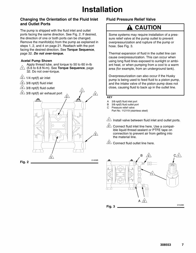
InstallationChanging the Orientation of the Fluid Inletand Outlet Ports
The pump is shipped with the fluid inlet and outletports facing the same direction. See Fig. 2. If desired,the direction of one or both ports can be changed.Remove the manifold(s) from the pump as explained insteps 1, 2, and 4 on page 21. Reattach with the portfacing the desired direction. See Torque Sequence,page 32. Do not over-torque.
Fig. 2
1
3
4
2 1/4 npt(f) air inlet
01459B
Apply thread lube, and torque to 50 to 60 in-lb(5.6 to 6.8 N-m). See Torque Sequence, page32. Do not over-torque.
3/8 npt(f) fluid inlet
3/8 npt(f) fluid outlet5 3/8 npt(f) air exhaust port
1
2
3
5
4
Acetal Pump Shown
Fluid Pressure Relief Valve
CAUTIONSome systems may require installation of a pres-sure relief valve at the pump outlet to preventoverpressurization and rupture of the pump orhose. See Fig. 3.
Thermal expansion of fluid in the outlet line cancause overpressurization. This can occur whenusing long fluid lines exposed to sunlight or ambi-ent heat, or when pumping from a cool to a warmarea (for example, from an underground tank).
Overpressurization can also occur if the Huskypump is being used to feed fluid to a piston pump,and the intake valve of the piston pump does notclose, causing fluid to back up in the outlet line.
Connect fluid outlet line here.
Fig. 3
KEY
A 3/8 npt(f) fluid inlet portB 3/8 npt(f) fluid outlet portC Pressure relief valve
Part No. 112119 (stainless steel)
1
3
2 Connect fluid inlet line here. Use a compat-ible liquid thread sealant or PTFE tape onconnection to prevent air from getting intothe material line.
Install valve between fluid inlet and outlet ports.
C
A
B 1
2
3
01539B
1

8 308553
Installation
Fig. 4
KEY
A Husky 307 PumpB Bleed-Type Master Air Valve
(required for pump)C Air Supply HoseD Air Line Quick DisconnectE Master Air Valve (for accessories)F Air Line FilterG Gun Air RegulatorH Pump Air RegulatorJ Fluid Drain Valve (required)K Fluid Recirculation LineL Fluid Suction LineM Surge Tank and FilterN Fluid Supply HoseP Gun Air Supply HoseR Air Spray GunS Floor StandY Ground Wire (required; see page 5
for installation instructions)
H
J
STAND-MOUNTED AIR SPRAY INSTALLATION
01433B
A
C
D
G
K
L
M
NP
R
S
Y
F BE
Fig. 5
PAIL-MOUNTED HVLP AIR SPRAY INSTALLATION
01434B
H
J
A
C
D G
K
L
M
NP
R
Y
S
KEY
A Husky 307 PumpB Bleed-Type Master Air Valve
(required for pump)C Air Supply LineD Air Line Quick DisconnectE Master Air Valve (for accessories)F Air Line FilterG Gun Air RegulatorH Pump Air RegulatorJ Fluid Drain Valve (required)K AgitatorL Fluid Suction LineM Fluid RegulatorN Fluid Supply HoseP Gun Air Supply HoseR HVLP Air Spray GunS Pail CoverY Ground Wire (required; see page 5
for installation instructions)
FB E

308553 9
Installation
Fig. 6
BUNG-MOUNT TRANSFER INSTALLATION
01444B
Y
J
C
N
L
F H BE
KEY
A Husky 307 PumpB Bleed-Type Master Air Valve
(required for pump)C Air Supply LineD Air Line Quick DisconnectE Master Air Valve (for accessories)F Air Line FilterH Pump Air RegulatorJ Fluid Drain Valve (required)L Fluid Suction LineM Fluid Inlet FilterN Fluid Supply HoseY Ground Wire (required; see page 5
for installation instructions)
M
AD
Fig. 7 01457B
WALL-MOUNT TRANSFER INSTALLATION
Y
J
NC
L
F H BE
KEY
A Husky 307 PumpB Bleed-Type Master Air Valve
(required for pump)C Air Supply LineD Air Line Quick DisconnectE Master Air Valve (for accessories)F Air Line FilterH Pump Air RegulatorJ Fluid Drain Valve (required)L Fluid Suction LineN Fluid Supply HoseS Wall BracketT Bung AdapterY Ground Wire (required; see page 5
for installation instructions)
S
T
D
A

10 308553
InstallationAir Exhaust Ventilation
FIRE AND EXPLOSION HAZARDBe sure to read FIRE OR EXPLOSIONHAZARD and TOXIC FLUID HAZARDon page 3, before operating this pump.
Be sure the system is properly ventilatedfor your type of installation. You mustvent the exhaust to a safe place, away
from people, animals, food handling areas, and allsources of ignition when pumping flammable orhazardous fluids.
Diaphragm failure will cause the fluid beingpumped to exhaust with the air. Place an appropri-ate container at the end of the air exhaust line tocatch the fluid. See Fig. 8.
WARNING
The air exhaust port is 3/8 npt(f). Do not restrict the airexhaust port. Excessive exhaust restriction can causeerratic pump operation.
To exhaust to a remote location:
1. Remove the muffler (11) from the pump airexhaust port.
PRESSURIZED EQUIPMENT HAZARDTo reduce the risk of serious eye injuryfrom ice particles, never operate thepump with the air exhaust port open. Ice
may form during pump operation, and ice particleswill be ejected from the port along with the exhaustair. If the muffler (11) is removed, always connectan air exhaust hose to the exhaust port.
WARNING
2. Install an electrically conductive air exhaust hose(X) and connect the muffler to the other end of thehose. The minimum size for the air exhaust hoseis 3/8 in. (10 mm) ID. If a hose longer than 15 ft(4.57 m) is required, use a larger diameter hose.Avoid sharp bends or kinks in the hose.
3. Place a container (Z) at the end of the air exhaustline to catch fluid in case a diaphragm ruptures. Ifthe fluid is flammable, ground the container. SeeFig. 8.
Fig. 8
VENTING EXHAUST AIR (Submerged Installation Shown)See Fig. 4 for accessories
In a submerged installation (as shown), all wetted and non-wettedpump parts must be compatible with the fluid being pumped.
01445A
Z
X
11

308553 11
OperationPressure Relief Procedure
PRESSURIZED EQUIPMENT HAZARDThe system pressure must be manually relieved toprevent the system from starting or spraying acci-dentally. To reduce the risk of an injury from acci-dental spray from the gun, splashing fluid, or mov-ing parts, follow the Pressure Relief Procedurewhenever you� Are instructed to relieve the pressure� Stop spraying� Check or service any of the system equipment� Install or clean the spray tips
WARNING
1. Shut off the air to the pump.
2. Open the dispensing valve, if used.
3. Open the fluid drain valve to relieve all fluid pres-sure, having a container ready to catch the drain-age.
Flush the Pump Before First Use
The pump was tested in water. If water could contami-nate the fluid you are pumping, flush the pump thor-oughly with a compatible solvent. Follow the stepsunder Starting and Adjusting the Pump.
Starting and Adjusting the Pump
TOXIC FLUID HAZARDHazardous fluid or toxic fumes cancause serious injury or death if splashedin the eyes or on the skin, inhaled, or
swallowed. Do not lift a pump under pressure. Ifdropped, the fluid section may rupture. Alwaysfollow the Pressure Relief Procedure abovebefore lifting the pump.
WARNING
1. Be sure the pump is properly grounded. ReadFIRE OR EXPLOSION HAZARD on page 3.
2. Check all fittings to be sure they are tight. Be sureto use a compatible liquid thread sealant or PTFEtape on all male threads. Tighten the fluid inlet andoutlet fittings snugly. Do not overtighten the fittingsinto the pump.
3. Place the suction tube (if used) in the fluid to bepumped.
4. Place the end of the fluid hose (N) into anappropriate container. Close the fluid drain valve(J).
5. With the pump air regulator (H) closed, open allbleed-type master air valves (B, E).
6. If the fluid hose has a dispensing device, hold itopen while continuing with the following step.Slowly open the air regulator (H) until the pumpstarts to cycle. Allow the pump to cycle slowly untilall air is pushed out of the lines and the pump isprimed.
If you are flushing, run the pump long enough tothoroughly clean the pump and hoses. Close theair regulator. Remove the suction tube from thesolvent and place it in the fluid to be pumped.
Pump Shutdown
WARNINGTo reduce the risk of serious injury whenever youare instructed to relieve pressure, always follow thePressure Relief Procedure at left.
At the end of the work shift, relieve the pressure.

12 308553
Troubleshooting
WARNINGTo reduce the risk of serious injury whenever youare instructed to relieve pressure, always follow thePressure Relief Procedure on page 11.
1. Relieve the pressure before checking or servicingthe equipment.
2. Check all possible problems and causes beforedisassembling the pump.
PROBLEM CAUSE SOLUTION
The pump will not cycle, or cyclesonce and stops.
The air valve is stuck or dirty. Turn the reset shaft (21).
Disassemble and clean the airvalve. See pages 18, 19.
Use filtered air.
The detent link (22) is worn or broken.
Replace the detent link (22) and ball(8). See pages 18, 19.
The springs (3, 6) and/or valve cup(5) and plate (13) are broken ordamaged.
Replace these parts. See pages 18, 19.
The pump cycles at stall or fails tohold pressure at stall.
The check valves or o-rings (108)are leaking.
Replace these parts. See page 21.
The check balls (301) or seat (201)are worn.
Replace these parts. See page 21.
The check ball (301) is wedged inthe seat (201).
Replace the ball. See page 21.
There is excessive air leakage fromthe exhaust port.
The air valve cup (5) or plate (13) isworn.
Replace these parts. See pages 18, 19.
The shaft seals (30�) are worn. Replace the seals. See page 23.
The pump operates erratically. The suction line is clogged. Inspect; clear the line.
The check valve balls (301) aresticking or leaking.
Clean or replace the balls. See page 21.
The diaphragm (401) is ruptured. Replace the diaphragm. See page 23.

308553 13
TroubleshootingPROBLEM CAUSE SOLUTION
There are air bubbles in the fluid. The suction line is loose, or there isa lack of thread sealant.
Tighten the suction line. Use a com-patible liquid thread sealant orPTFE tape on connections.
The diaphragm (401) is ruptured. Replace the diaphragm. See page 23.
The manifolds (102) are loose orthe o-rings (108) are damaged.
Tighten the manifold bolts (104) ornuts (106); replace the o-rings(108). See page 21.
The outer diaphragm plates (103)are loose.
Tighten the plates. See page 23.
There is fluid in the exhaust air. The diaphragm (401*) is ruptured. Replace the diaphragm. See page 23.
The outer diaphragm plates (103)are loose.
Tighten the plates. See page 23.
The pump exhausts air at stall. The air valve cup (5) or plate (13) isworn.
Replace these parts. See pages 18, 19.
The shaft seals (30�) are worn. Replace the seals. See page 23.
The pump exhausts air from theclamps.
The clamps (111) are loose. Tighten the clamp nuts (113). See page 14.
The pump exhausts air near the airvalve.
The air valve screws (15) are loose. Tighten the screws.See page 16.
The air valve o-ring (19) is damaged.
Inspect; replace the o-ring. See pages 18, 19.
The pump leaks fluid from thecheck valves.
The o-rings (108) are worn or damaged.
Inspect; replace the o-rings. See page 21.

14 308553
MaintenanceLubrication
The air valve is designed to operate unlubricated,however if lubrication is desired, every 500 hours ofoperation (or monthly) remove the hose from the pumpair inlet and add two drops of machine oil to the airinlet.
CAUTIONDo not over-lubricate the pump. Oil is exhaustedthrough the muffler, which could contaminate yourfluid supply or other equipment. Excessive lubrica-tion can also cause the pump to malfunction.
Flushing and Storage
WARNINGTo reduce the risk of serious injury whenever youare instructed to relieve pressure, always follow thePressure Relief Procedure on page 11.
Flush the pump when necessary to prevent the fluidyou are pumping from drying or freezing in the pumpand damaging it. Use a compatible solvent.
Before storing the pump, always flush the pump andrelieve the pressure.
Tightening Threaded Connections
Before each use, check all hoses for wear or damage,and replace as necessary. Check to be sure allthreaded connections are tight and leak-free.
Check fasteners. Tighten or retorque as necessary.Although pump use varies, a general guideline is toretorque fasteners every two months. See TorqueSequence, page 32.
Tightening the Clamps
When tightening the clamps (111), apply thread lubri-cant to the bolts and be sure to torque the nuts (113)to 50 to 60 in-lb (5.6 to 6.8 N�m). See Fig. 9. SeeTorque Sequence, page 32.
01446BFig. 9
1
111
Apply thread lube and torque nuts to 50 to 60 In-lb(5.6 to 6.8 N�m). See Torque Sequence, page 32.
1113
Preventive Maintenance Schedule
Establish a preventive maintenance schedule, basedon the pump’s service history. This is especially impor-tant for prevention of spills or leakage due to dia-phragm failure.

308553 15
Notes

16 308553
ServiceReplacing the Air Valve
Tools Required
� Torque wrench
� Phillips screwdriver
� O-ring pick
NOTE: Air Valve Kit 239952 is available. Partsincluded in the kit are marked with a dagger, for exam-ple (2�). A tube of general purpose grease (26�) issupplied in the kit. Install the kit as follows.
WARNINGTo reduce the risk of serious injury whenever youare instructed to relieve pressure, always follow thePressure Relief Procedure on page 11.
1. Relieve the pressure.
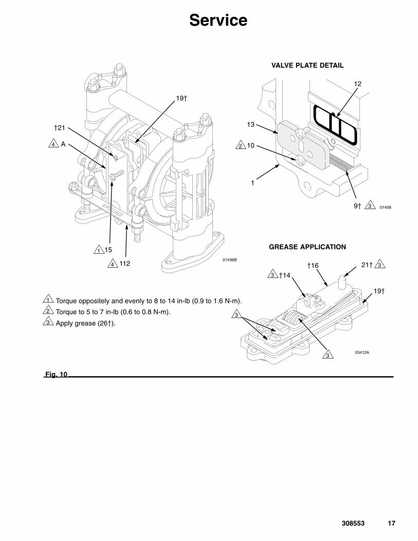
2. Unscrew the six mounting screws (15) and removethe air valve (A) from the pump. See Fig. 10.
3. Refer to the Valve Plate Detail in Fig. 10. Removethe two screws (10) holding the valve plate (13) tothe pump. Use an o-ring pick to remove the valveplate, seal (12), and bearing (9).
4. Apply grease (26�) to the bearing (9�). Install thebearing and the seal (12) in the pump housing (1).Install the valve plate (13) and secure with the twoscrews (10�), as shown. Torque the screws to5 to 7 in-lb (0.6 to 0.8 N-m).
5. Make certain the o-ring (19�) is in place on the airvalve cover (2�).
6. Apply grease (26�) where shown in Fig. 10.
7. Align the new air valve assembly so the reset shaft(21�) is at the top. Install the valve on the pump,making sure the valve saddle (14�) engages therecessed area on the diaphragm shaft (23). Installthe six screws (15) and torque oppositely andevenly, to 8 to 14 in-lb (0.9 to 1.6 N-m).
308553 17
Service
01436B
Fig. 10
1
3
2
�21
01458
1
VALVE PLATE DETAIL
GREASE APPLICATION
19�
15
Torque oppositely and evenly to 8 to 14 in-lb (0.9 to 1.6 N-m).
Torque to 5 to 7 in-lb (0.6 to 0.8 N-m).
Apply grease (26�).
3
112
1
2
4
4
9�
12
13
10A
�14
21��16
03412A
19�
3
3
3
3

18 308553
ServiceRepairing the Air Valve
Tools Required
� Torque wrench
� Phillips screwdriver
� O-ring pick
� Rubber mallet
Disassembly
WARNINGTo reduce the risk of serious injury whenever youare instructed to relieve pressure, always follow thePressure Relief Procedure on page 11.
1. Relieve the pressure.
2. Remove the air valve from the pump (see page16).
3. Remove the screw (15) and shift saddle (14). SeeFig. 11.
4. Disassemble the link assembly, consisting of theactuator link (16), spacer (17), detent link (22),spring (3), stop (4), and valve cup (5).
5. Remove the detent ball (8) and spring (6). Thedetent collar (7) is a press-fit and should not needremoval; if it does require replacement, you shouldalso replace the cover (2).
6. Remove the reset shaft (21), o-ring (20) andwasher (18).
7. Clean all parts and inspect for wear or damage.Replace as needed. See Reassembly, page 19.
Fig. 11
NOTE: ALL PARTS SHOWN ARE INCLUDED IN AIR VALVE KIT 239952.
01431A
�2
7�
�4
�18
�16
�20
�21
�22
�17
�14
�15
�3
5�
8�
6�19�

308553 19
ServiceReassembly
1. If the detent collar (7) was removed, carefullyinstall a new collar in a new cover (2), using arubber mallet. See Fig. 12.
2. Grease the spring (6) and place it in the collar (7).Grease the ball (8) and set it on the spring.
3. Grease the o-ring (20) and install it in the hole (H)in the cover (2). See Fig. 12. Slide the washer (18)onto the blunt end of the reset shaft (21). Insertthe shaft through the cover (2) until it seats.
4. Grease the spring (3). Place the link stop (4) insidethe spring.
Fig. 12
1
2
01437
�18
2�
6��8
7��21
Apply grease (26�).
Press fit with rubbermallet.
�20
1
1
11
2
H
5. Grease the detent link (22) and link spacer (17).Assemble the detent link, link spacer, and actuatorlink (16) as shown in Fig. 13. The raised bumps onthe links (22 and 16) must face up.
6. Squeeze the spring (3) and install it and the stop(4) in the link assembly. The spring tension willhold all these parts together. Grease the valve cup(5) and install it in the link assembly as shown.
7. Install the link assembly on the cover (2) so thepointed end of the reset shaft (21) fits through theholes in the links and the square part of the shaftengages the square hole. Make certain the bumpson the detent link (22) engage the ball (8).
Fig. 13
�17
�3
1
3
2
�16
2�
4�8�
5�
�22
Apply grease (26�).
Bumps face up.
Reset shaft square must engagewith square hole.
2
3
1
1
1
2
7505A
1
1
1

20 308553
Service8. Grease the inside surfaces of the shift saddle (14)
and install it as shown in Fig. 14. Hold the linkassembly firmly in place and install the screw (15).Torque to 7 to 9 in-lb (0.8 to 1.0 N-m). Install theo-ring (19) on the cover (2).
9. Reinstall the air valve as explained on page 16.
Fig. 14
1
2
Apply grease (26�).
Torque to 7 to 9 in-lb (0.8 to 1.0 N-m).
�2
�22
�5
19�
�14
15�
21�
1
1
1
1
2
7506A
CAUTIONDo not over-torque the manifold bolts (104). Doingso may cause the nuts (106) to spin in the hous-ings, damaging the cover (101).

308553 21
ServiceBall Check Valves
Tools Required
� Torque wrench
� 1/2” (13 mm) socket wrench
� O-ring pick
NOTE: A Fluid Section Repair Kit is available. Seepage 27 for the correct kit. Parts included in the kit aremarked with an asterisk, for example (301*). Use allthe parts in the kit for the best results. Always replacethe o-rings (108) with new ones whenever the old onesare removed.
WARNINGTo reduce the risk of serious injury whenever youare instructed to relieve pressure, always follow thePressure Relief Procedure on page 11.
1. Relieve the pressure. Disconnect all hoses.Remove the pump from its mounting.
2. Using a 1/2” socket wrench, remove the nuts (106)holding the top manifold (102) to the covers (101).Lift the manifold off the pump. See Fig. 15.
3. Remove the outer o-ring (108), ball guide (202),ball (301), seat (201), and inner o-ring (108) fromeach of the covers.
4. Turn the pump over. Pull the tie rods (104) out ofthe pump, leaving the four nuts (106) on the rods.Remove the feet (107) and lower manifold (102).
5. Remove the outer o-ring (108), seat (201), ball(301), ball guide (202), and inner o-ring (108) fromeach of the covers (101).
6. Clean all parts and inspect for wear or damage.Replace parts as needed.
7. Reassemble the intake ball checks in the bottom ofthe pump, following all notes in Fig. 15. Be surethe ball checks are assembled exactly as shown.
8. Set the lower manifold (102) and feet (107) inplace on the bottom of the pump.
9. Insert the long threads of each rod (104) throughthe feet and lower manifold. Push the rods upthrough the covers (101) until the nut (106) on theend of the rods bottoms on the foot. Make sure therods are pushed all the way through. Turn thepump upright (the rods are a slight interference fitand will hold the pump parts securely in place).
10. Reassemble the outlet ball checks in the top of thepump, following all notes in Fig. 15. Be sure theball checks are assembled exactly as shown. Toavoid leaks, run your finger over the o-rings (108)to ensure that they are properly seated.
11. Install the top manifold (102) and four nuts (106).Torque to 50 to 60 in-lb (5.6 to 6.8 N-m). SeeTorque Sequence, page 32. Do not over-torque.

22 308553
Service
02457CFig. 15
102
101
102
107
201*
202*
201*
202*
106
106
1
3
4
2
Apply thread lubricant.
Do not over-torque.
Flat side faces ball.
Beveled end up.
Torque to 50 to 60 in-lb (5.6 to6.8 N-m). See Torque Se-quence, page 32.
5
301*
108*
108*
301*
108*
108*
1
3
2
4 5
4 5
3
2
104
6 Long threads at top.
6

308553 23
ServiceDiaphragm Repair
Tools Required
� Torque wrench
� One 7/16” (11 mm) and two 1/2” (13 mm) socket wrenches
� Phillips screwdriver
� O-ring pick
� 13/32” EZY-OUT bearing extractor
� Rubber mallet
� Vise with soft jaws
DisassemblyNOTE: A Fluid Section Repair Kit is available. Seepage 27 for the correct kit. Parts included in the kit aremarked with an asterisk, for example (401*). Use allthe parts in the kit for the best results.
WARNINGTo reduce the risk of serious injury whenever youare instructed to relieve pressure, always follow thePressure Relief Procedure on page 11.
1. Relieve the pressure. Disconnect all hoses.
2. Remove the air valve from the pump (see page16).
3. Remove the manifolds (102) and disassemble theball check valves as explained on page 21. Alwaysreplace the o-rings (108) with new ones.
4. Using a 7/16” socket wrench, remove the clampnuts (113) and the grounding strip (112). Loosenthe clamps (111) and slip them over the housing(1). Pull the covers (101) off the pump, thenremove the clamps from the housing. See theDetail in Fig. 16.
5. Using a 1/2” socket wrench on both outer dia-phragm plates (103), unscrew one plate from thediaphragm shaft (23). Remove one diaphragm(401), inner diaphragm plate (118), and o-ring(404). Pull the opposite diaphragm assembly andthe diaphragm shaft out of the pump housing (1).See Fig. 16. Clamp the shaft in a vise with softjaws and unscrew the outer plate (103), thendisassemble the remaining diaphragm assembly.
6. Inspect the diaphragm shaft (23�) for wear orscratches. If it is damaged, check the bearings(31�) also. Replace parts as needed. To removethe bearings, place a 13/32 EZY-OUT in a vise.Position the pump housing (1) over the EZY-OUT(see Fig. 16). Turn the housing in the directionshown by the arrows to remove the bearing.
7. Hook the shaft seals (30�) with an o-ring pick andpull them out of the housing (1).
8. Clean all parts and inspect for wear or damage.Replace parts as needed.

24 308553
ServiceReassembly1. Install the shaft seals (30�) in the housing (1).
Using a rubber mallet, carefully drive the bearings(31�) flush into the housing so the holes face out.See Fig. 16.
2. Grease the diaphragm shaft (23�) and slide it intothe housing (1). Install the o-rings (404*) in thegrooves of the housing.
3. Assemble the inner diaphragm plates (118), dia-phragms (401*), and outer diaphragm plates (103)as shown in Fig. 16. Apply medium-strength (blue)Loctite� or equivalent to the threads of the fluid-side plates (103), and torque the plates to 75 to 85in-lb (8.5 to 9.6 N�m) at 100 rpm maximum using a1/2-in. socket wrench. Do not over-torque. Theseparts must be assembled correctly.
CAUTIONDo not over-torque the outer diaphragm plates(103). Doing so will damage the hex heads.
4. When installing the covers (101), slip the clamps(111) over the housing (1) before positioning thecovers. See the Detail in Fig. 16. Engage thenotches in the covers with the locator tabs on thehousing, then position the clamps over both parts.The clamp bolts should be on the air valve side ofthe housing, and pointing down toward the bottomof the pump. Install the grounding strip on thebolts. Apply thread lubricant to the bolts, theninstall the clamp nuts (113). Using a 7/16” socketwrench, torque the nuts to 50 to 60 in-lb (5.6 to 6.8N�m). See Torque Sequence, page 32.
5. Reassemble the ball check valves and manifoldsas explained on page 21. Always install newo-rings (108*), and make sure they are properlyseated.
6. Reinstall the air valve, using the six mountingscrews (15). See Fig. 10.

308553 25
1
3
4
2
01441C
01442
102
101
106
102
107
112
*401118
402*
1
1
13/32 IN. EZY-OUT
01443
CUTAWAY VIEW OF DIAPHRAGMASSEMBLIES IN PUMP HOUSING
1
31�
DETAIL OF BEARING REMOVAL USING EZY-OUT
*401
AIR SIDEFLUID SIDE
301**108
*108
111
301*
403*
3
118 23
30�
404*
Apply thread lubricant.
Grease shaft.
Do not over-torque.
Round side must face toward diaphragm.
Flat side faces ball.
Beveled end up.
Apply medium-strength (blue) Loctite� orequivalent. Torque to 75 to 85 in-lb(8.5 to 9.6 N-m) at 100 rpm maximum using a1/2-in. socket wrench.
Torque to 50 to 60 in-lb (5.6 to 6.8 N-m). See Torque Sequence, page 32.
6
7
8
9
104
202*
201*
202*
201*
106
23�
*404
10301440
101
111
1
10 Notches mustengagetabs.
DETAIL OF CLAMPS AND COVERS
113 810
2
7
2
2
4
4
3
3
8
1
16
9
5
Acetal Model Shown
113
Service1068
8

26 308553
Pump MatrixHusky 307 Acetal and Polypropylene Pumps, Series FYour Model No. is marked on the pump’s serial plate. To determine the Model No. of your pump from the followingmatrix, select the six digits which describe your pump, working from left to right. The first digit is always D,designating Husky diaphragm pumps. The remaining five digits define the materials of construction. For example, apump with a polypropylene air motor, acetal fluid section, acetal seats, PTFE balls, and PTFE diaphragms is ModelD 3 1 2 1 1. To order replacement parts, refer to the part lists on pages 28 to 29. The digits in the matrix do notcorrespond to the ref. nos. in the parts drawing and lists.
DiaphragmPump Air Motor Fluid Section – Seats Balls Diaphragms
D (for all pumps) 3 (polypropylene) 1 (acetal) – 1 (not used) 1 (PTFE) 1 (PTFE)
2 (polypropylene) – 2 (acetal) 2 (not used) 2 (not used)
A (acetal BSPT) – 3 (316 sst) 3 (316 sst) 3 (not used)
B (polypropylene BSPT)
– 4 (not used) 4 (not used) 4 (not used)
– 5 (not used) 5 (TPE) 5 (TPE)
– 6 (not used) 6 (Santoprene�) 6 (Santoprene�)
– 7 (not used) 7 (buna-N) 7 (buna-N)
– 8 (not used) 8 (not used) 8 (not used)
– 9 (polypropylene) 9 (not used) 9 (not used)
Husky 307 Acetal and Polypropylene Pumps, Series F continued
Model 248167Same as D31277 except with split inlets/outlets.
Model 248168Same as D31255 except with split inlets/outlets.
Model 248169Same as D32255 except with split inlets/outlets.
Model 248170Same as D32977 except with split inlets/outlets.

308553 27
Repair Kit MatrixFor Husky 307 Acetal and Polypropylene Pumps, Series FRepair Kits may be ordered separately. To repair the air valve, order Part No. 239952 (see page 28). Parts includedin the Air Valve Repair Kit are marked with a symbol in the parts list, for example (2�).
To repair your pump, select the six digits which describe your pump from the following matrix, working from left toright. The first digit is always D, the second digit is always 0 (zero), and the third is always 3. The remaining threedigits define the materials of construction. Parts included in the kit are marked with an asterisk in the parts list, forexample (201*). For example, if your pump has acetal seats, PTFE balls, and PTFE diaphragms, order Repair KitD 0 3 2 1 1. If you only need to repair certain parts (for example, the diaphragms), use the 0 (null) digits for theseats and balls, and order Repair Kit D 0 3 0 0 1. The digits in the matrix do not correspond to the ref. nos. inthe parts drawing and lists on pages 28 to 29.
DiaphragmPump Null O-rings – Seats Balls Diaphragms
D (for all pumps) 0 (for all pumps) 3 (PTFE) – 0 (null) 0 (null) 0 (null)
– 1 (not used) 1 (PTFE) 1 (PTFE)
– 2 (acetal) 2 (not used) 2 (not used)
– 3 (316 sst) 3 (316 sst) 3 (not used)
– 4 (not used) 4 (not used) 4 (not used)
– 5 (not used) 5 (TPE) 5 (TPE)
– 6 (not used) 6 (Santoprene�) 6 (Santoprene�)
– 7 (not used) 7 (buna-N) 7 (buna-N)
– 8 (not used) 8 (not used) 8 (not used)
– 9 (polypropylene) 9 (not used) 9 (not used)

28 308553
PartsAir Motor Parts List (Matrix Column 2)
DigitRef.No. Part No. Description Qty
3 1 187705 HOUSING, center;polypropylene; see page 29
1
2� 187706 COVER, air valve; polypropylene
1
3� 187722 SPRING, compression;sst
1
4� 187853 STOP, link; acetal 1
5� 192675 CUP, valve; acetal 1
6� 187728 SPRING, compression;sst
1
7� 187730 COLLAR, detent; sst 1
8� 111629 BALL, detent; carbide 1
9� 187726 BEARING, link; acetal;see page 29
1
10 111631 SCREW, thread-forming;1/4–20; 0.375 in. (9.5mm) long; see page 29
2
11 112933 MUFFLER; see page 29 1
12 187719 SEAL, plate, valve;buna-N; see page 29
1
13 187720 PLATE, valve; sst; see page 29
1
14� 187718 SADDLE, shift; acetal 1
15� 111630 SCREW, thread-forming;10–14 size; 0.75 in. (19 mm) long; see belowand page 29
7
DigitRef.No. Part No. Description Qty
16� 187724 LINK, actuator; sst 1
17� 188175 SPACER, link; acetal 1
18� 111750 WASHER, plain; sst 1
19� 111624 O-RING; buna-N 1
20� 111625 O-RING; buna-N 1
21� 187727 SHAFT, reset; sst 1
22� 192526 LINK, detent; sst 1
23� 191781 SHAFT, diaphragm; sst; see page 29
1
26� 111920 GREASE, general pur-pose; 0.375 oz. (10.5 g);not shown
1
27� 100179 NUT, hex; 10–24; see page 29
1
28� 102790 SCREW; 10–24;0.75 in. (19 mm) long; see page 29
1
29� 100718 LOCKWASHER, int.tooth; no. 10; see page29
1
30� 113704 PACKING, u-cup; fluoroe-lastomer
2
31� 191779 BEARING; acetal 2
� These parts are included in Air Valve Kit 239952, whichmay be purchased separately. The kit includes only onescrew (15), shown below, and a tube of grease (26).
� These parts are included in Diaphragm Shaft Kit 239014,which may be purchased separately.
� Not supplied with Polypropylene pump.
01431A
�2
7�
�4
�18
�16
�20
�21
�22
�17
�14
�15
�3 5�
8�6� 19�

308553 29
Parts
* Included in Pump Repair Kit, which may be purchasedseparately. See page 27.
� Included in Air Valve Kit 239952, which may be pur-chased separately. See parts list on page 28.
Replacement Danger and Warning labels, tags andcards are available at no cost.
� Included in Diaphragm Shaft Kit 239014, which may bepurchased separately.
� Not supplied with Polypropylene pump.
102
101
106
102
107
27�
28�
29�
113
112�
401*
118
31�
1
13
9�12
11
10
15
103
*404
104
23� 109
106
104
106
106
101
102
102
107
108*
108*
108*
108*
201*
201*
202*
202*
301*
301*
�
Detail of Polypropylene Models
Acetal Model Shown
30�
01429E
106

30 308553
PartsFluid Section Parts List (Matrix Column 3)
DigitRef.No. Part No. Description Qty
1 101 187701 COVER, fluid; acetal withconductive sst fibers
2
102 235337 MANIFOLD; acetal withconductive sst fibers
2
103 187711 PLATE, fluid side; acetal 2
104 188999 ROD, tie; 5/16–18 4
106 117233 NUT; 5/16–18 8
107 187721 FEET 2
108 111603 O-RING; PTFE 8
109
187732 LABEL, warning 1
111 187820 CLAMP 2
112 191079 STRIP, grounding 1
113 112499 NUT, clamp; 1/4–28 2
118 191741 PLATE, air side; sst 2
2 101 187702 COVER, fluid; polypropylene
2
102 235338 MANIFOLD; polypropylene
2
103 187712 PLATE, fluid side; polypropylene
2
104 188999 ROD, tie; 5/16–18 4
106 117233 NUT; 5/16–18 8
107 187721 FEET 2
108 111603 O-RING; PTFE 8
109
187732 LABEL, warning 1
111 187820 CLAMP 2
113 112499 NUT, clamp; 1/4–28 2
118 191741 PLATE, air side; sst 2
DigitRef.No. Part No. Description Qty
A 101 187701 COVER, fluid; acetal withconductive sst fibers
2
102 239146 MANIFOLD; acetal withconductive sst fibers;BSPT
2
103 187711 PLATE, fluid side; acetal 2
104 188999 ROD, tie; 5/16–18 4
106 117233 NUT; 5/16–18 8
107 187721 FEET 2
108 111603 O-RING; PTFE 8
109
187732 LABEL, warning 1
111 187820 CLAMP 2
112 191079 STRIP, grounding 1
113 112499 NUT, clamp; 1/4–28 2
118 191741 PLATE, air side; sst 2
B 101 187702 COVER, fluid; polypropylene
2
102 239147 MANIFOLD; polypropylene; BSPT
2
103 187712 PLATE, fluid side; polypropylene
2
104 188999 ROD, tie; 5/16–18 4
106 117233 NUT; 5/16–18 8
107 187721 FEET 2
108 111603 O-RING; PTFE 8
109
187732 LABEL, warning 1
111 187820 CLAMP 2
113 112499 NUT, clamp; 1/4–28 2

308553 31
PartsSeat Parts List (Matrix Column 4)
DigitRef.No. Part No. Description Qty
2 201* 187709 SEAT; acetal 4
202* 187707 GUIDE; acetal 4
3 201* 190245 SEAT; 316 stainless steel 4
202* 187707 GUIDE; acetal 4
9 201* 187710 SEAT; polypropylene 4
202* 187708 GUIDE; polypropylene 4
Ball Parts List (Matrix Column 5)
DigitRef.No. Part No. Description Qty
1 301* 111626 BALL; PTFE 4
3 301* 112926 BALL; 316 stainless steel 4
5 301* 111627 BALL; TPE 4
6 301* 113221 BALL; Santoprene� 4
7 301* 112884 BALL; buna-N 4
Diaphragm Parts List (Matrix Column 6)
DigitRef.No. Part No. Description Qty
1 401* 187716 DIAPHRAGM; PTFE 2
404* 166071 O-RING; buna-N 2
5 401* 187715 DIAPHRAGM; TPE 2
404* 166071 O-RING; buna-N 2
6 401* 190754 DIAPHRAGM; Santoprene�
2
404* 166071 O-RING; buna-N 2
7 401* 190209 DIAPHRAGM; buna-N 2
404* 166071 O-RING; buna-N 2

32 308553
Torque SequenceAlways follow torque sequence when instructed to torque fasteners.
1. Left/Right Fluid CoversTorque bolts to 50–60 in–lb (5.6–6.8 N�m)
FRONT VIEW
12
2. Outlet ManifoldTorque bolts to 50–60 in–lb (5.6–6.8 N�m)
TOP VIEW
3
4 6
5
4 6
3. Inlet ManifoldTorque bolts to 50–60 in–lb (5.6–6.8 N�m)
BOTTOM VIEW
79
108

308553 33
Technical DataPumps with PTFE Diaphragms
Maximum fluid working pressure 100 psi (0.7 MPa, 7 bar). . . Air pressure operating range 20 to 100 psi. . . . . . . . . . . . . . . .
(0.14 to 0.7 MPa, 1.4 to 7 bar)Maximum air consumption 5.5 SCFM (see chart). . . . . . . . . . Maximum free flow delivery 6.5 gpm (24.6 l/min). . . . . . . . . . . Maximum pump speed 330 cpm. . . . . . . . . . . . . . . . . . . . . . . . . Maximum suction lift 7 ft (2.1 m) dry; 12 ft (3.7 m) wet. . . . . . Maximum size pumpable solids 1/16 in. (1.6 mm). . . . . . . . . . Sound power level,
at full flow: (100 psi [0.7 MPa, 7 bar) 85 dBa. . . . . . . . . . . . Sound power level,
at 70 psi (0.48 MPa, 4.8 bar) and 1 gpm (3.8 lpm) 78 dBa. Operating temperature range 40 to 150� F. . . . . . . . . . . . . . . .
(4.4 to 65.5� C)
Air inlet size 1/4 npt(f). . . . . . . . . . . . . . . . . . . . . . . . . . . . . . . . . . Fluid inlet and outlet size. 3/8 npt(f). . . . . . . . . . . . . . . . . . . . . . Wetted parts Vary by model. See pages 28 and 30.. . . . . . . .
Acetal models include acetal with conductive sst fibers.Non-wetted external parts acetal, polyester (labels),. . . . . . . .
glass-filled polypropylene with conductive SST fibers, 303, 304 and 316 stainless steel
Weight Acetal Pumps: 5.25 lb (2.4 kg). . . . . . . . . . . . . . . . . . . . Polypropylene Pumps: 4.75 lb (2.2 kg)
* Sound power level measured per ISO standard 9614–2.
Loctite is a registered trademark of the Loctite Corporation.Santoprene is a registered trademark of the MonsantoCompany.
0
20
40
60
80
100
120
0 1 2 3 4 5 6 7 8
TEST CONDITIONSPump tested in water with inlet submerged.
(7.6) (15.2) (22.7) (30.3)
(2.8)
(1.4)
(4.2)
KEY FLUID PRESSURE AND FLOW
SCFM AIR CONSUMPTION
100 psi air(7 bar)
Example of Finding Pump Air Consumption and Air Pressure at a Specific Fluid Deliv-ery and Discharge Head: To supply 3 gpm (11.4 liters) fluid flow (horizontal scale) at 50 psi(3.5 bar) discharge head pressure (vertical scale) requires 3 scfm (.084 m�/min) air con-sumption at 70 psi (4.9 bar) inlet air pressure.
FLUID FLOW GPM (lpm)
70 psi air(4.9 bar)
40 psi air(2.8 bar)
5 scfm(0.14 m�/min)
psi(bar)
feet(meters) 280(85.3)
240(73.2)
200(61.0)
160(48.8)
120(36.6)
80(24.4)
40(12.2)
0
0
20
40
60
80
100
0 5 10 15 20 25
PUMPING RATE DECREASE AT DIFFERENT SUCTION LIFTS
SUCTION LIFT IN FEET (METERS)(1.52) (3.05) (4.57) (6.1) (7.62)
EXAMPLE: At a suction lift of 10 ft (3.05 m), the pump flow rate will be decreased by 20 percent.
(5.6)
(7.0)
(8.4)
20 psi air(1.4 bar)
3 scfm(.084 m�/min)
(3.8) (11.4) (19.0) (26.5)

34 308553
Technical DataPumps with TPE or Buna-N Diaphragms
Maximum fluid working pressure 100 psi (0.7 MPa, 7 bar). . . Air pressure operating range 20 to 100 psi. . . . . . . . . . . . . . . .
(0.14 to 0.7 MPa, 1.4 to 7 bar)Maximum air consumption 5.5 SCFM (see chart). . . . . . . . . . Maximum free flow delivery 7 gpm (26.5 l/min). . . . . . . . . . . . Maximum pump speed 330 cpm. . . . . . . . . . . . . . . . . . . . . . . . . Maximum suction lift 12 ft (3.7 m) dry; 21 ft (6.4 m) wet. . . . . Maximum size pumpable solids 1/16 in. (1.6 mm). . . . . . . . . . Sound power level,
at full flow: (100 psi [0.7 MPa, 7 bar) 85 dBa. . . . . . . . . . . . Sound power level,
at 70 psi (0.48 MPa, 4.8 bar) and 1 gpm (3.8 lpm) 78 dBa. Operating temperature range 40 to 150� F. . . . . . . . . . . . . . . .
(4.4 to 65.5� C)
Air inlet size 1/4 npt(f). . . . . . . . . . . . . . . . . . . . . . . . . . . . . . . . . . Fluid inlet and outlet size. 3/8 npt(f). . . . . . . . . . . . . . . . . . . . . . Wetted Parts Vary by model. See pages 28 and 30.. . . . . . . .
Acetal models include acetal with conductive sst fibers.Non-wetted external parts acetal, polyester (labels),. . . . . . . .
glass-filled polypropylene with conductive SST fibers,303, 304 and 316 stainless steel
Weight Acetal Pumps: 5.25 lb (2.4 kg). . . . . . . . . . . . . . . . . . . . Polypropylene Pumps: 4.75 lb (2.2 kg)
* Sound power level measured per ISO standard 9614–2.
Loctite is a registered trademark of the Loctite Corporation.Santoprene is a registered trademark of the MonsantoCompany.
0
20
40
60
80
100
120
0 1 2 3 4 5 6 7 8
TEST CONDITIONSPump tested in water with inlet submerged.
(7.6) (15.2) (22.7) (30.3)
(2.8)
(1.4)
(4.2)
100 psi air(7 bar)
FLUID FLOW GPM (lpm)
70 psi air(4.9 bar)
40 psi air(2.8 bar)
5 scfm(0.14 m�/min)
280(85.3)
240(73.2)
200(61.0)
160(48.8)
120(36.6)
80(24.4)
40(12.2)
0
0
20
40
60
80
100
0 5 10 15 20 25
PUMPING RATE DECREASE AT DIFFERENT SUCTION LIFTS
SUCTION LIFT IN FEET (METERS)(1.52) (3.05) (4.57) (6.1) (7.62)
EXAMPLE: At a suction lift of 10 ft (3.05 m), the pump flow rate will be decreased by 20 percent.
(5.6)
(7.0)
(8.4)
20 psi air(1.4 bar)
3 scfm(.084 m�/min)
(3.8) (11.4) (19.0) (26.5)
Example of Finding Pump Air Consumption and Air Pressure at a Specific Fluid Deliv-ery and Discharge Head: To supply 3 gpm (11.4 liters) fluid flow (horizontal scale) at 50 psi(3.5 bar) discharge head pressure (vertical scale) requires 3 scfm (.084 m�/min) air consump-tion at 70 psi (4.9 bar) inlet air pressure.
KEY FLUID PRESSURE AND FLOW
SCFM AIR CONSUMPTION
psi(bar)
feet(meters)

308553 35
Dimensions
PUMP MOUNTING HOLE PATTERN
SIDE VIEW
5 in.(127 mm)
0654
WALL BRACKET 224-835
Four 0.438 in. (11 mm) dia. holes(to mount bracket to wall)
9.0 in.(228.6 mm)
6.74 in.(171.2 mm)
8 in.(203 mm)(WALL VIEW)
07316B
0.28 in.(7 mm)Diameter (4)
3.50 in.(89 mm)
6.30 in.(160 mm)
7.24 in.(184 mm)
FRONT VIEW
1.13 in.(28.5 mm)
1.06 in.(27 mm)
1/4 npt(f)Air Inlet
3/8 npt(f)Air Exhaust
(muffler included)
8.13 in.(206.5 mm)
8.12 in.(206.5 mm)
6.05 in.(153.5 mm)
3.14 in.(80 mm)
6.18 in.(157 mm)
.66 in.(17 mm)
3/8 npt(f)Fluid Inlet5.3 in.
(134.5 mm)
2.53 in.(64.5 mm)
3/8 npt(f)Fluid Outlet

36 308553
Graco Standard Husky Pump WarrantyGraco warrants all equipment referenced in this document which is manufactured by Graco and bearing its name to be free from de-fects in material and workmanship on the date of sale to the original purchaser for use. With the exception of any special, extended, orlimited warranty published by Graco, Graco will, for a period of five years from the date of sale, repair or replace any part of the equip-ment determined by Graco to be defective. This warranty applies only when the equipment is installed, operated and maintained inaccordance with Graco’s written recommendations.
This warranty does not cover, and Graco shall not be liable for general wear and tear, or any malfunction, damage or wear caused byfaulty installation, misapplication, abrasion, corrosion, inadequate or improper maintenance, negligence, accident, tampering, or sub-stitution of non–Graco component parts. Nor shall Graco be liable for malfunction, damage or wear caused by the incompatibility ofGraco equipment with structures, accessories, equipment or materials not supplied by Graco, or the improper design, manufacture,installation, operation or maintenance of structures, accessories, equipment or materials not supplied by Graco.
This warranty is conditioned upon the prepaid return of the equipment claimed to be defective to an authorized Graco distributor forverification of the claimed defect. If the claimed defect is verified, Graco will repair or replace free of charge any defective parts. Theequipment will be returned to the original purchaser transportation prepaid. If inspection of the equipment does not disclose any defectin material or workmanship, repairs will be made at a reasonable charge, which charges may include the costs of parts, labor, andtransportation.
THIS WARRANTY IS EXCLUSIVE, AND IS IN LIEU OF ANY OTHER WARRANTIES, EXPRESS OR IMPLIED, INCLUDING BUTNOT LIMITED TO WARRANTY OF MERCHANTABILITY OR WARRANTY OF FITNESS FOR A PARTICULAR PURPOSE.
Graco’s sole obligation and buyer’s sole remedy for any breach of warranty shall be as set forth above. The buyer agrees that no otherremedy (including, but not limited to, incidental or consequential damages for lost profits, lost sales, injury to person or property, or anyother incidental or consequential loss) shall be available. Any action for breach of warranty must be brought within six (6) years of thedate of sale.
GRACO MAKES NO WARRANTY, AND DISCLAIMS ALL IMPLIED WARRANTIES OF MERCHANTABILITY AND FITNESS FORA PARTICULAR PURPOSE, IN CONNECTION WITH ACCESSORIES, EQUIPMENT, MATERIALS OR COMPONENTS SOLDBUT NOT MANUFACTURED BY GRACO. These items sold, but not manufactured by Graco (such as electric motors, switches,hose, etc.), are subject to the warranty, if any, of their manufacturer. Graco will provide purchaser with reasonable assistance in makingany claim for breach of these warranties.
In no event will Graco be liable for indirect, incidental, special or consequential damages resulting from Graco supplying equipmenthereunder, or the furnishing, performance, or use of any products or other goods sold hereto, whether due to a breach of contract,breach of warranty, the negligence of Graco, or otherwise.
FOR GRACO CANADA CUSTOMERSThe Parties acknowledge that they have required that the present document, as well as all documents, notices and legal proceedingsentered into, given or instituted pursuant hereto or relating directly or indirectly hereto, be drawn up in English. Les parties reconnais-sent avoir convenu que la rédaction du présente document sera en Anglais, ainsi que tous documents, avis et procédures judiciairesexécutés, donnés ou intentés, à la suite de ou en rapport, directement ou indirectement, avec les procédures concernées.
Graco InformationFor the latest information about Graco products, visit www.graco.com.For patent information, see www.graco.com/patents.
TO PLACE AN ORDER, contact your Graco distributor or call to identify the distributor closest to you: Phone: 612–623–6921 or Toll Free: 1–800–328–0211 Fax: 612–378–3505
All written and visual data contained in this document reflects the latest product information available at the time of publication.Graco reserves the right to make changes at any time without notice.
Original instructions. This manual contains English. MM 308553
Graco Headquarters: MinneapolisInternational Offices: Belgium, China, Japan, Korea
GRACO INC. AND SUBSIDIARIES P.O. BOX 1441 MINNEAPOLIS, MN 55440–1441 USACopyright 1995, Graco Inc. All Graco manufacturing locations are registered to ISO 9001.
www.graco.comRevision ZAD, January 2015